EP2990192B2 - Moule de formage a compensation de tolerance - Google Patents
Moule de formage a compensation de tolerance Download PDFInfo
- Publication number
- EP2990192B2 EP2990192B2 EP15182414.1A EP15182414A EP2990192B2 EP 2990192 B2 EP2990192 B2 EP 2990192B2 EP 15182414 A EP15182414 A EP 15182414A EP 2990192 B2 EP2990192 B2 EP 2990192B2
- Authority
- EP
- European Patent Office
- Prior art keywords
- tool
- clamping plate
- press
- pressure forming
- spring
- Prior art date
- Legal status (The legal status is an assumption and is not a legal conclusion. Google has not performed a legal analysis and makes no representation as to the accuracy of the status listed.)
- Active
Links
Images



Classifications
-
- B—PERFORMING OPERATIONS; TRANSPORTING
- B21—MECHANICAL METAL-WORKING WITHOUT ESSENTIALLY REMOVING MATERIAL; PUNCHING METAL
- B21D—WORKING OR PROCESSING OF SHEET METAL OR METAL TUBES, RODS OR PROFILES WITHOUT ESSENTIALLY REMOVING MATERIAL; PUNCHING METAL
- B21D37/00—Tools as parts of machines covered by this subclass
- B21D37/04—Movable or exchangeable mountings for tools
-
- B—PERFORMING OPERATIONS; TRANSPORTING
- B21—MECHANICAL METAL-WORKING WITHOUT ESSENTIALLY REMOVING MATERIAL; PUNCHING METAL
- B21D—WORKING OR PROCESSING OF SHEET METAL OR METAL TUBES, RODS OR PROFILES WITHOUT ESSENTIALLY REMOVING MATERIAL; PUNCHING METAL
- B21D24/00—Special deep-drawing arrangements in, or in connection with, presses
- B21D24/02—Die-cushions
-
- B—PERFORMING OPERATIONS; TRANSPORTING
- B30—PRESSES
- B30B—PRESSES IN GENERAL
- B30B15/00—Details of, or accessories for, presses; Auxiliary measures in connection with pressing
- B30B15/007—Means for maintaining the press table, the press platen or the press ram against tilting or deflection
-
- B—PERFORMING OPERATIONS; TRANSPORTING
- B30—PRESSES
- B30B—PRESSES IN GENERAL
- B30B15/00—Details of, or accessories for, presses; Auxiliary measures in connection with pressing
- B30B15/02—Dies; Inserts therefor; Mounting thereof; Moulds
- B30B15/026—Mounting of dies, platens or press rams
-
- B—PERFORMING OPERATIONS; TRANSPORTING
- B30—PRESSES
- B30B—PRESSES IN GENERAL
- B30B15/00—Details of, or accessories for, presses; Auxiliary measures in connection with pressing
- B30B15/06—Platens or press rams
-
- B—PERFORMING OPERATIONS; TRANSPORTING
- B30—PRESSES
- B30B—PRESSES IN GENERAL
- B30B15/00—Details of, or accessories for, presses; Auxiliary measures in connection with pressing
- B30B15/06—Platens or press rams
- B30B15/061—Cushion plates
-
- B—PERFORMING OPERATIONS; TRANSPORTING
- B30—PRESSES
- B30B—PRESSES IN GENERAL
- B30B15/00—Details of, or accessories for, presses; Auxiliary measures in connection with pressing
- B30B15/06—Platens or press rams
- B30B15/062—Press plates
- B30B15/064—Press plates with heating or cooling means
-
- B—PERFORMING OPERATIONS; TRANSPORTING
- B30—PRESSES
- B30B—PRESSES IN GENERAL
- B30B15/00—Details of, or accessories for, presses; Auxiliary measures in connection with pressing
- B30B15/06—Platens or press rams
- B30B15/065—Press rams
- B30B15/067—Press rams with means for equalizing the pressure exerted by a plurality of press rams
-
- B—PERFORMING OPERATIONS; TRANSPORTING
- B30—PRESSES
- B30B—PRESSES IN GENERAL
- B30B15/00—Details of, or accessories for, presses; Auxiliary measures in connection with pressing
- B30B15/06—Platens or press rams
- B30B15/068—Drive connections, e.g. pivotal
-
- B—PERFORMING OPERATIONS; TRANSPORTING
- B30—PRESSES
- B30B—PRESSES IN GENERAL
- B30B15/00—Details of, or accessories for, presses; Auxiliary measures in connection with pressing
- B30B15/16—Control arrangements for fluid-driven presses
- B30B15/24—Control arrangements for fluid-driven presses controlling the movement of a plurality of actuating members to maintain parallel movement of the platen or press beam
- B30B15/245—Control arrangements for fluid-driven presses controlling the movement of a plurality of actuating members to maintain parallel movement of the platen or press beam using auxiliary cylinder and piston means as actuating members
-
- C—CHEMISTRY; METALLURGY
- C21—METALLURGY OF IRON
- C21D—MODIFYING THE PHYSICAL STRUCTURE OF FERROUS METALS; GENERAL DEVICES FOR HEAT TREATMENT OF FERROUS OR NON-FERROUS METALS OR ALLOYS; MAKING METAL MALLEABLE, e.g. BY DECARBURISATION OR TEMPERING
- C21D1/00—General methods or devices for heat treatment, e.g. annealing, hardening, quenching or tempering
- C21D1/62—Quenching devices
- C21D1/673—Quenching devices for die quenching
Definitions
- the present invention relates to a press forming tool comprising an upper tool and a lower tool according to the features in the preamble of patent claim 1.
- Press forming tools for producing sheet metal forming components are known from the prior art.
- a sheet metal blank is placed in the press forming tool and then formed by moving an upper tool and a lower tool towards each other.
- an upper tool is usually lowered with the help of a press ram, whereby when the upper tool and blank and the blank and the lower tool come into contact, the blank begins to be formed until the upper tool and lower tool are closed in such a way that a mold cavity remains between the upper tool and lower tool when the blank is integrated.
- the formed blank is then finally formed in the mold cavity to form the component to be produced by press forming.
- hot forming and press hardening for hardenable steel alloys are known in the prior art.
- blanks made of a hardenable steel alloy are heated to a temperature above AC3 so that they are completely austenitized. These heated blanks are then placed in the press forming tool and formed while warm. After press forming has been completed, with the press forming tool completely closed, the component is then preferably cooled in the press forming tool so quickly that quench hardening occurs.
- This process is also known as press hardening. If, due to the tolerances mentioned above, there is no direct contact between the surface of the component in the press forming tool and the inside of the tool surfaces, the cooling performance is reduced due to minimal air gaps in these areas and a lower cooling rate is achieved.
- a press forming tool according to the preamble of claim 1 is known, in which a lever mechanism is inserted between the press ram and the tool clamping plate of an upper tool in order to distribute the force evenly, adapted to the deformation, to the workpiece to be formed.
- the object of the present invention is therefore to provide a press forming tool in which a compensation option for the upper tool and/or lower tool is provided, so that production tolerances occurring during press forming, in particular in the case of tools that fall multiple times, are reduced and, if necessary, better heat dissipation occurs during quench hardening.
- the press forming tool has an upper tool and a lower tool, which can be moved towards one another and, when the press forming tool is closed, a mold cavity is formed between the upper tool and the lower tool.
- a blank formed into a press forming component comes into contact in a mold cavity, with the surface of the blank coming into contact with a tool surface of the upper tool and with a tool surface of the lower tool.
- a tool clamping plate is arranged on a press ram and/or a press table, with an upper tool or lower tool that is movable relative to the tool clamping plate being mounted on the tool clamping plate with the inclusion of at least one spring-elastic adjusting element.
- a press ram is provided in the area of the upper tool, whereby the press ram has a corresponding holder for a tool clamping plate, whereby the upper tool itself is then coupled to the tool clamping plate.
- a press table is provided on which the tool clamping plate is fixed and then in turn the lower tool is fixed to the tool clamping plate.
- the design variant of the elastic adjusting element on the upper tool is particularly preferred, especially considering the tool costs and operating costs. This has the particular advantage that only one tool, i.e. the upper tool, is spring-mounted, which reduces the manufacturing costs of the tool. At the same time, this offers the advantage that no dirt falls into the spring-elastic adjusting elements due to gravity when changing tools or operating the tool.
- the upper tool or the lower tool is now mounted so that it can move relative to the tool clamping plate.
- the tool clamping plate ensures that the spring-elastic adjusting elements distributed on the tool clamping plate transfer the press force evenly to the upper tool. If an imbalance occurs, this is caused by the relative movement and the forming forces that are then distributed differently across the various spring-elastic adjusting elements, resulting in a shift and thus a homogenization of the forming forces to be transferred.
- the press forming tool according to the invention is designed as a hot forming and press hardening tool, almost full-surface contact of the tool surfaces with the surface of the blank or the press forming component produced is thus always ensured. According to the invention, this results in the particular advantage that when quench hardening is carried out, it is ensured that the component is homogeneous and, in particular, has the desired quenching temperature and thus the desired hardness structure in all required areas. If cooling rates are lower due to minimal air gaps, either stronger cooling capacities and/or longer time windows are used to reliably ensure that the components to be press hardened have the desired hardness structure properties.
- the tool clamping plate is particularly preferably coupled to the press table, in particular screwed, or the tool clamping plate is coupled to the press ram, in particular screwed. If the tool clamping plate according to the invention is designed with a spring-elastic adjusting element on the upper tool and lower tool, the press table would then be coupled to a tool clamping plate and the press ram to another tool clamping plate.
- the advantage here is that it is provided in this way and then only the forming tool parts or tool segment parts, i.e. the upper tool and the lower tool for the press forming of different products, have to be replaced. This results in significantly more cost-effective tool management, especially when changing production, making improvements and/or replacing worn tool parts.
- the spring-elastic adjusting elements are arranged in parallel rows offset from one another on the tool clamping plate.
- a row consists of several, in particular 1 to 50, particularly preferably 2 to 30 and very particularly preferably 3 to 20 adjusting elements, with at least 2, preferably again 2 to 30, in particular 3 to 20 rows of adjusting elements being arranged offset from one another parallel to one another.
- the rows themselves are also particularly preferably the same distance from one another as the individual adjusting elements in a row. This results in a pattern of spring-elastic adjusting elements that is evenly distributed over the tool clamping plate, so that the press forming force can be distributed accordingly homogeneously.
- the adjusting elements are arranged distributed on the tool clamping plate, in particular distributed asymmetrically.
- the distribution of the spring-elastic adjusting elements is adapted to the back of the contour of the upper tool or lower tool. This makes it possible, for example, to take into account a special shape of the press-formed component to be produced.
- more spring-elastic adjusting elements thus a larger number or density of adjusting elements per area, can be arranged in areas where forming forces are concentrated in order to compensate for the occurrence of increased forming forces compared to areas in which only lower forming forces are necessary.
- At least individual spring adjusting elements are blockable. This would be particularly preferred for spring adjusting elements arranged in a row, so that, for example, an entire row can be blocked at a time. Within the scope of the invention, however, it would also be conceivable that individual spring adjusting elements can be blocked in a targeted manner.
- the spring-elastic adjusting elements are designed in particular as mechanical springs.
- Helical compression springs are used for this purpose.
- disc springs, helical disc springs and/or sleeve springs are also conceivable.
- an arrangement is conceivable in such a way that the spring-elastic adjusting elements themselves are arranged under pre-tension between the upper tool and the tool clamping plate or the lower tool and the tool clamping plate. In this case, a corresponding pre-tension is necessary, in particular during assembly or when changing the upper tool and lower tool.
- the spring-elastic actuating element can be designed as a pneumatic and/or hydraulic spring element.
- the pneumatic and/or hydraulic spring element can be operated passively. This means that due to the suspension characteristics, a corresponding spring characteristic is established as the press pressure increases and the press force is passed on to the sheet metal blank to be formed or to the formed component at the bottom dead center of the press, and thus the locking force.
- the spring-elastic actuating element can be designed as an actuator and to be actively controllable.
- the press force transmitted via the spring-elastic actuating element can be increased again by applying an operating pressure and any remaining gap in the cavity between the tool surface and the surface of the component can be closed by the increased press force and an associated relative movement of the upper tool and/or lower tool.
- a corresponding operating pressure is applied to the spring-elastic actuating elements while the press is closing.
- a damping bearing is arranged between a rear side of the upper tool and the tool clamping plate or between a rear side of the lower tool and the tool clamping plate.
- the damping bearing is preferably a damping layer to prevent metal impacts.
- the damping bearing prevents metal impacts in particular when the press forming tool is opened, so that there is no contact between the upper tool and the tool clamping plate or the lower tool and the tool clamping plate that could damage the production process.
- the damping bearing can be made of plastic or a rubber-like material, for example, and is applied in a flat and/or strip-like manner. It can also be applied at specific points.
- the back of the upper tool or the back of the lower tool in particular would come into contact with the support strips at least in some areas and would then transfer the forming force directly and not just via the spring-elastic actuating element. This prevents unwanted displacement due to excessive relative movement and/or unwanted forming behavior of the blank.
- the lower tool or the upper tool, or sometimes both tools are each designed in segments, with the individual segments being mounted on the tool clamping plate so that they can move relative to one another. These are then also mounted so that they can move relative to the tool clamping plate.
- the invention provides that at least two upper tools or at least two lower tools are arranged next to one another on a tool clamping plate, the two upper tools or the two lower tools being mounted so that they can move relative to one another.
- this is to be understood as a tool that falls multiple times, so that identical components can be produced with one press stroke due to identical upper tools and lower tools arranged next to one another or different but identical components.
- different upper tools or lower tools are arranged transversely to the press ram or on the press table, so that different components can be produced with one press stroke.
- the relative movement can ensure that all components have the required degree of deformation and in particular the required system contacts for a pressing process during a press stroke, so that the desired hardness structures can be set in a targeted manner.
- a centering mandrel is arranged between the press ram and the press table, which guides the closing movement of the press ram and the press table linearly, in particular vertically, in the press stroke direction. This ensures that the relative movement is carried out exclusively in the press stroke direction due to the spring-elastic actuating element and not transversely to the press stroke direction.
- the centering mandrel is arranged between the upper tool and the lower tool, so that this in particular can carry out a corresponding relative movement in the transverse direction. to the press stroke.
- the smallest possible tolerance or displacement, and thus lateral guidance is provided, in particular in the horizontal direction, while linear guidance is provided in the vertical direction, and therefore in the press stroke direction, so that the upper tool or the lower tool can move relative to the tool clamping plate as specified by the spring-elastic adjusting elements.
- the invention provides that the upper tool and/or the lower tool are coupled to the tool clamping plate in a relatively movable manner by means of sliding blocks, wherein a sliding block has a guide section and an abutment section.
- the sliding blocks are particularly preferably T-shaped for this purpose.
- the T-leg forms the guide section, which also simultaneously guides linearly in the vertical direction and avoids a relative movement transverse to the press stroke direction.
- the crosspiece of the T forms an abutment section, so that a relative movement is limited when the crosspiece is reached. If, for example, the tool clamping plate is written on the upper tool, it is coupled to the press ram.
- FIG. 1 A press forming tool 101 is shown in a side cross-sectional view.
- the press forming tool 101 has a press ram 102 shown in the image plane from top to bottom, with the upper tool 103 (not shown in more detail) being coupled to the press ram 102.
- a press force F is now applied via the press ram 102 in relation to a vertical direction V, which at the same time corresponds to the press stroke movement, and the upper tool 103 and a lower tool 104 are closed.
- V vertical direction
- the upper tool 103 and a lower tool 104 are closed.
- Between the upper tool 103 and the lower tool 104 there remains a mold cavity 105 with a blank (not shown in more detail), with the blank particularly preferably being fully in contact with the respective tool surfaces 106, 107 within the scope of the invention. comes into contact.
- the invention provides that a tool clamping plate 109 is arranged on a press table 108 and various spring-elastic adjusting elements 110 are arranged between the lower tool 104 and the tool clamping plate 109.
- spring-elastic adjusting elements 110 By means of the spring-elastic adjusting elements 110, it is possible for the lower tool 104 to Figure 2 exaggerated relative movement is carried out primarily in the vertical direction V.
- a guide (not shown in more detail) prevents the lower tool 104 from slipping in the horizontal direction H itself.
- a media line 111 by means of which the spring-elastic actuating elements 110 can be actively controlled.
- Actively controllable means in particular within the scope of the invention that the spring characteristics and/or damping characteristics of the spring-elastic actuating element 110 can be adjusted. Alternatively or additionally, actively controllable within the scope of the invention can also mean that the spring-elastic actuating elements 110 can be blocked in this way.
- the tool clamping plate 109 itself is firmly coupled to the press table 108 by means of bolts 112.
- the lower tool 104 is also coupled to the tool clamping plate 109 in turn via sliding blocks 113.
- the sliding blocks 113 are shown greatly enlarged for the sake of quick clarity.
- the sliding blocks 113 have an end stop 114 in the area of a T-shaped web, so that no relative movement between the tool clamping plate 109 and the lower tool 104 is possible beyond the end stop 114. Furthermore, both the upper tool 103 and the lower tool 104 have cooling channels 115 through which a corresponding cooling medium can be passed so that the press hardening can be carried out. In the embodiment according to Figure 2 Additionally or alternatively, a tool clamping plate 109 could be arranged between the press ram 102 and the upper tool 103.
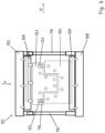
- FIG. 3a and b Shown in the Figures 3a and b is an alternative design variant in cross-sectional and longitudinal section view.
- the press forming tool 101 according to Figure 3 has a press ram 102 and a press table 108.
- the lower tool 104 is fixed on a tool clamping plate 109, whereby the tool clamping plate 109 itself is coupled to the press table 108 by means of bolts 112.
- no spring-elastic adjusting elements are integrated between the tool clamping plate 109 and the lower tool 104. These are shown here integrated on the upper tool 103, whereby they can also be actively controlled via a media line 111.
- the advantage of this design variant in particular is that no dirt falls between the upper tool 103 and the tool clamping plate 109 due to gravity in the vertical direction V and thus free mobility is always possible for the execution of the relative movement.
- the tool clamping plate 109 is in turn attached to the press ram 102 by means of bolts 112. Also shown here are corresponding cooling channels 115.
- Figure 4 shows a design variant of a press forming tool 101 according to the invention as a four-fold falling tool.
- four upper tools 103.1, 103.2, 103.3, 103.4 are shown next to one another on two tool clamping plates 109.1, 109.2, which are also arranged next to one another on the press ram 102.
- Four lower tools 104.1, 104.2, 104.3, 104.4 are designed to correspond to the four upper tools 103.1, 103.2, 103.3, 103.4, with the four lower tools 104.1, 104.2, 104.3, 104.4 each being arranged in pairs on corresponding tool clamping plates 109.3, 109.4 on the press table 108.
- the incoming upper tool 103.1, 103.2, 103.3, 103.4 and the lower tool 104.1, 104.2, 104.3, 104.4 can thus align themselves relative to one another in such a way that when the bottom dead center is reached, a corresponding uniform and full-surface system contact and/or tolerance compensation takes place.
- the two tool pairs on a tool clamping plate 109 can also be two sequential process stages. For example, hot forming can be carried out in the first tool pair and a cooling stage in the form of press hardening in the second tool pair. Both stages are then carried out in the same press cycle.
- the spring-elastic bearing can, in particular, again accommodate the tool expansion required for each process stage and which differs from one another. Also shown schematically or by way of example are spring-elastic adjusting elements 110 between the tool clamping plate 109 and the respective upper tool 103.
- FIG. 5 a and b shows a sectional view through a tool shown here falling twice.
- two upper tools 103.1, 103.2 and two lower tools 104.1, 104.2 are each arranged on a tool clamping plate 109.
- the upper tools 103 have the spring-elastic adjusting elements 110 according to the invention between themselves and the tool clamping plate 109.
- Figure 6 shows a design variant of the press forming tool 101 according to the invention with an externally arranged centering mandrel 116.
- the individual tool clamping plates 109 to align with one another and/or for the upper tool 103 and lower tool 104 to align with one another based on a respective centering mandrel 116.
- a respective centering mandrel 116 is also shown in the upper tool 103 or lower tool 104. The respective centering mandrel then protrudes, in particular with respect to the lower tool 104 shown here, and engages in a centering opening 124 in the upper tool 103.
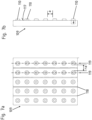
- Figures 7 a and b show a tool clamping plate 109 according to the invention in plan view and side view. It can be seen that the spring-elastic adjusting elements 110 protrude from a surface 117 of the tool clamping plate 109. These are spaced apart by a distance a from each other. Also shown in the plan view according to Figure 7a that the individual rows 119 also have a corresponding row spacing ra between each other. Preferably, the row spacing ra is equal to the spacing a between the individual spring-elastic adjusting elements 110. Also shown are clamping slots 118 for inserting sliding blocks 113 (not shown in detail), so that the upper tool and the lower tool can be coupled on a tool clamping plate 109.
- the spring-elastic adjusting elements 110 can also be designed in the form of cylinders, for example cylinder covers, which in turn then accommodate the spring-elastic adjusting element 110, for example in the form of a helical spring, and protect it from wear, damage and contamination.
- the spring-elastic adjusting elements 110 or cylinders particularly preferably have a stroke of up to 50 mm, in particular up to 30 mm and preferably up to 10 mm, relative to the surface 117 of the tool clamping plate 109 and in particular a stroke of 5 mm, in particular up to 2 mm, preferably less than 1 mm, relative to the surface 117 of the tool clamping plate 109.
- the lower spring-elastic actuating element 110 related to the image plane that it is at least partially mounted in the tool clamping plate 109 and protrudes with a part opposite the surface 117 of the tool clamping plate 109.
- the spring-elastic actuating element 110 is completely mounted in the tool clamping plate 109 and then moved out of the operating position when required; this design variant is conceivable in particular with active spring-elastic actuating elements 110.
- FIG. 8 Also presented in Figure 8 is the schematic coupling option of an upper tool 103 to a tool clamping plate 109 by means of double-T sliding blocks 120.
- the spring-elastic adjusting elements 110 hold the upper tool 103 at a distance b from the surface 117 of the tool clamping plate 109.
- the double-T sliding block 120 is provided with a damping bearing 125 on its respective T-leg 121, so that when the opening movement is carried out there is no impact due to reaching the respective abutment section.
- the double-T sliding block 120 can, as shown here, move into a cavity 122 in the tool clamping plate 109 when the bottom dead center is reached. Alternatively, it is conceivable that a cavity 122 is present in both the upper tool 103 and the tool clamping plate 109.
Landscapes
- Engineering & Computer Science (AREA)
- Mechanical Engineering (AREA)
- Chemical & Material Sciences (AREA)
- Materials Engineering (AREA)
- Thermal Sciences (AREA)
- Crystallography & Structural Chemistry (AREA)
- Physics & Mathematics (AREA)
- Metallurgy (AREA)
- Organic Chemistry (AREA)
- Shaping Metal By Deep-Drawing, Or The Like (AREA)
- Press Drives And Press Lines (AREA)
- Moulds For Moulding Plastics Or The Like (AREA)
- Casting Or Compression Moulding Of Plastics Or The Like (AREA)
Claims (9)
- Outil de moulage par pression (101) pour la fabrication de pièces formées en tôle, présentant un outil supérieur (103) et un outil inférieur (104) qui sont mobiles l'un par rapport à l'autre et, lorsque l'outil de moulage par pression (101) est fermé, une cavité de moule (105) est réalisée entre l'outil supérieur (103) et l'outil inférieur (104), dans lequel l'outil de moulage par pression (101) présente un poussoir de presse (102), une table de presse (108) et une plaque de serrage d'outil (109) qui est agencée sur le poussoir de presse (102) et/ou la table de presse (108), dans lequel un outil supérieur (103) ou un outil inférieur (104) mobile par rapport à celui-ci est monté sur la plaque de serrage d'outil (109) avec insertion d'au moins un élément de réglage (110) élastique à ressort, caractérisé en ce qu'au moins deux outils supérieurs (103.1, 103.2, 103.3, 103.4) ou au moins deux outils inférieurs (104.1, 104.2, 104.3, 104.4) sont agencés l'un à côté de l'autre sur la plaque de serrage d'outil (109), dans lequel les deux outils supérieurs (103.1, 103.2, 103.3, 103.4) ou les deux outils inférieurs (104.1, 104.3, 104.4) sont montés mobiles les uns par rapport aux autres, dans lequel l'outil de moulage par pression (101) est réalisé sous la forme d'un outil de formage à chaud et de durcissement à la presse et des canaux de refroidissement (115) sont réalisés dans l'outil supérieur (103) et/ou dans l'outil inférieur (104) et l'outil supérieur (103) et/ou l'outil inférieur (104) est/sont couplé(s) de manière mobile à la plaque de serrage d'outil (109) au moyen de coulisseaux (113), dans lequel un coulisseau (113) présente une section de guidage et une section de butée.
- Outil de moulage par pression selon la revendication 1, caractérisé en ce que la plaque de serrage d'outil (109) est couplée, en particulier vissée, à la table de presse (108), ou en ce que la plaque de serrage d'outil (109) est couplée, en particulier vissée, au poussoir de presse (102).
- Outil de moulage par pression selon la revendication 1 ou 2, caractérisé en ce que les éléments de réglage (110) sont disposés sur ou dans la plaque de serrage d'outil (109), en particulier dans des rangées (119) décalées parallèlement les unes aux autres, ou en ce que les éléments de réglage (110) sont répartis sur ou dans la plaque de serrage d'outil (109).
- Outil de moulage par pression selon l'une quelconque des revendications 1 à 3, caractérisé en ce que l'élément de réglage élastique à ressort (110) est réalisé sous la forme d'un ressort mécanique, en particulier d'un ressort de compression hélicoïdal, ou sous la forme d'un élément de ressort pneumatique et/ou hydraulique.
- Outil de moulage par pression selon l'une quelconque des revendications 1 à 4, caractérisé en ce que les éléments de réglage élastiques à ressort (110) sont réalisés sous la forme d'éléments d'actionnement et peuvent être commandés de manière active.
- Outil de moulage par pression selon l'une quelconque des revendications précédentes, caractérisé en ce qu'un palier d'amortissement est agencé entre un côté arrière de l'outil supérieur (103) et la plaque de serrage d'outil (109) ou un côté arrière de l'outil inférieur (104) et la plaque de serrage d'outil (109).
- Outil de moulage par pression selon l'une quelconque des revendications précédentes, caractérisé en ce que l'outil inférieur (104) ou l'outil supérieur (103) est réalisé de manière segmentée, dans lequel les segments individuels sont montés de manière mobile les uns par rapport aux autres sur la plaque de serrage d'outil (109).
- Outil de moulage par pression selon l'une quelconque des revendications précédentes, caractérisé en ce qu'un mandrin de centrage (116) est agencé entre le poussoir de presse (102) et la table de presse (108) et/ou en ce qu'un mandrin de centrage (116) est agencé entre l'outil supérieur (103) et l'outil inférieur (104), dans lequel le déplacement de fermeture du poussoir de presse (102) et de la table de presse (108) et/ou de l'outil supérieur (103) et de l'outil inférieur (104) est guidé linéairement par le mandrin de centrage (116).
- Outil de moulage par pression selon l'une quelconque des revendications précédentes, caractérisé en ce que l'outil supérieur (103) et la plaque de serrage (109) et/ou l'outil inférieur (104) et la plaque de serrage (109) sont couplés au moyen de boulons filetés venant en prise de manière traversante avec les éléments de réglage élastiques à ressort (110) et/ou intégrant les éléments de réglage élastiques à ressort (110).
Applications Claiming Priority (1)
| Application Number | Priority Date | Filing Date | Title |
|---|---|---|---|
| DE102014112325.5A DE102014112325B4 (de) | 2014-08-27 | 2014-08-27 | Pressumformwerkzeug mit Toleranzausgleich |
Publications (3)
| Publication Number | Publication Date |
|---|---|
| EP2990192A1 EP2990192A1 (fr) | 2016-03-02 |
| EP2990192B1 EP2990192B1 (fr) | 2022-04-13 |
| EP2990192B2 true EP2990192B2 (fr) | 2024-10-30 |
Family
ID=54007616
Family Applications (1)
| Application Number | Title | Priority Date | Filing Date |
|---|---|---|---|
| EP15182414.1A Active EP2990192B2 (fr) | 2014-08-27 | 2015-08-25 | Moule de formage a compensation de tolerance |
Country Status (5)
| Country | Link |
|---|---|
| US (1) | US10322443B2 (fr) |
| EP (1) | EP2990192B2 (fr) |
| CN (1) | CN105382098B (fr) |
| DE (1) | DE102014112325B4 (fr) |
| ES (1) | ES2919865T5 (fr) |
Families Citing this family (20)
| Publication number | Priority date | Publication date | Assignee | Title |
|---|---|---|---|---|
| DE102014119545A1 (de) | 2014-12-23 | 2016-06-23 | Benteler Automobiltechnik Gmbh | Federnd gelagertes segmentiertes Warmumformwerkzeug und Verfahren zur Herstellung eines warmumform- und pressgehärteten Stahlbauteils mit scharf berandetem Übergangsbereich |
| CN106513486B (zh) * | 2017-01-03 | 2018-08-31 | 安徽工业大学 | 一种基于并联机构的板料充液拉深成形方法 |
| DE102017118492A1 (de) * | 2017-08-14 | 2019-02-14 | Kirchhoff Automotive Deutschland Gmbh | Pressenwerkzeug |
| CN108043959A (zh) * | 2017-11-08 | 2018-05-18 | 浙江吉利汽车研究院有限公司 | 一种热成形装置 |
| DE102018106312A1 (de) * | 2018-03-19 | 2019-09-19 | Auto-Kabel Management Gmbh | Toleranzausgleich für Flachteile |
| CN108574241A (zh) * | 2018-05-10 | 2018-09-25 | 安徽自动化仪表有限公司 | 一种使用方便的电缆桥架 |
| DE102019109700B4 (de) * | 2019-04-12 | 2021-09-23 | Schuler Pressen Gmbh | Presse zur Aufnahme einer Werkzeugeinheit und Verfahren zum betriebsbereiten Anordnen der Werkzeugeinheit in der Aufnahme der Presse |
| US20210039423A1 (en) * | 2019-08-07 | 2021-02-11 | Entrust Datacard Corporation | Ribbon impresser/indenter for plastic cards |
| CN110681751B (zh) * | 2019-10-14 | 2020-12-01 | 南通东海机床制造集团有限公司 | 一种冲压机械加工设备 |
| JP6840448B1 (ja) * | 2020-01-31 | 2021-03-10 | 旭精機工業株式会社 | プレス機及びプレス製品の製造方法 |
| DE102020204004A1 (de) | 2020-03-27 | 2021-09-30 | Robert Bosch Gesellschaft mit beschränkter Haftung | Ausgleichsvorrichtung und Pressvorrichtung |
| CN112277357A (zh) * | 2020-09-21 | 2021-01-29 | 常德非凡照明电器有限公司 | 一种led灯灯芯用压制设备 |
| US12570031B2 (en) | 2020-09-25 | 2026-03-10 | Lego A/S | Mold tool for injection molding |
| WO2022114113A1 (fr) * | 2020-11-27 | 2022-06-02 | 日本製鉄株式会社 | Dispositif de presse et procédé permettant de fabriquer un article moulé à la presse |
| US12528263B2 (en) * | 2020-11-27 | 2026-01-20 | Nippon Steel Corporation | Press apparatus and method of manufacturing press-formed product |
| CN112757686A (zh) * | 2020-12-30 | 2021-05-07 | 中国兵器装备集团自动化研究所 | 具有柔性的上冲头装置 |
| DE102021100281B3 (de) | 2021-01-11 | 2022-05-05 | Audi Aktiengesellschaft | Umformwerkzeug sowie Verfahren zum Betreiben eines Umformwerkzeugs |
| US12384069B1 (en) | 2021-04-07 | 2025-08-12 | Nicholas R. Bechen | Apparatus, system, and method for producing and positioning multi-tire structural features |
| CN115318948B (zh) * | 2022-07-27 | 2025-06-03 | 中机精冲科技(福建)有限公司 | 一种异形大尺寸精冲件加工工艺及生产线 |
| CN116460206A (zh) * | 2023-03-21 | 2023-07-21 | 华南理工大学 | 一种板料冲压成形回弹局部耦合控制方法 |
Citations (1)
| Publication number | Priority date | Publication date | Assignee | Title |
|---|---|---|---|---|
| JP2005199300A (ja) † | 2004-01-15 | 2005-07-28 | Komatsu Sanki Kk | プレス加工方法 |
Family Cites Families (26)
| Publication number | Priority date | Publication date | Assignee | Title |
|---|---|---|---|---|
| US2400004A (en) * | 1942-06-08 | 1946-05-07 | Republic Aviat Corp | Means for forming sheet metal |
| US3194047A (en) * | 1962-04-24 | 1965-07-13 | Budd Co | Method of making a metal sandwich structure panel |
| US3197996A (en) * | 1962-12-07 | 1965-08-03 | Budd Co | Redrawing dies for deep drawing to varying depths |
| JPS5994533A (ja) * | 1982-11-19 | 1984-05-31 | Hitachi Ltd | 熱間式絞り、張り出し同時成形装置 |
| DE4415577B4 (de) * | 1994-05-03 | 2007-02-22 | Müller Weingarten AG | Einrichtung zur Kompensation bzw. gezielten Einstellung von Durchbiegungen in Pressen der Umformtechnik |
| JPH08168897A (ja) | 1994-12-16 | 1996-07-02 | Nisshinbo Ind Inc | 金型の分割制御が可能なプレス加工機 |
| DE19718857A1 (de) * | 1997-05-03 | 1998-11-05 | Dieffenbacher Gmbh Maschf | Preß-/Heizplatte für hydraulische Kurztakt-und Beschichtungspressen |
| JP3685961B2 (ja) | 1999-08-23 | 2005-08-24 | 本田技研工業株式会社 | 成形用プレス装置 |
| ITFI20010043A1 (it) * | 2001-03-16 | 2002-09-16 | Longinotti Meccanica S R L | Sistema di compensazione degli errori di dosaggio su presse per mattonelle a piu' impronte,in specie per mattonelle monostrato o similari |
| ITMO20020259A1 (it) * | 2002-09-29 | 2004-03-21 | Fabio Casolari | Stampo per formatura di piastrelle ceramiche. |
| JP2006305621A (ja) * | 2005-05-02 | 2006-11-09 | Bridgestone Corp | プレス金型及び板金加工方法 |
| EP1803549A1 (fr) * | 2005-12-30 | 2007-07-04 | Robert Bürkle GmbH | Plaque chauffante pour presse à plateaux |
| EP1803548A1 (fr) * | 2005-12-30 | 2007-07-04 | Robert Bürkle GmbH | Plaque chauffante pour presse à plateaux |
| BRPI0710220A2 (pt) | 2006-05-09 | 2011-08-02 | Amino Corp | prensa de acionamento inferior |
| DE102008034996B4 (de) | 2008-07-25 | 2010-11-18 | Benteler Automobiltechnik Gmbh | Vorrichtung zum Warmformen, Presshärten und Schneiden eines Halbzeugs aus härtbarem Stahl |
| US7823430B2 (en) * | 2008-07-29 | 2010-11-02 | Gm Global Technology Operations, Inc. | Open press thermal gap for QPF forming tools |
| JP2010042426A (ja) * | 2008-08-13 | 2010-02-25 | Ihi Corp | プレス機械のスライド構造 |
| DE102010027554A1 (de) | 2010-07-19 | 2012-01-19 | Thyssenkrupp Umformtechnik Gmbh | Umformwerkzeug und Verfahren zum Warmumformen und partiellen Presshärten eines Werkstückes aus Stahlblech |
| DE102011011013B4 (de) | 2011-02-11 | 2017-07-13 | Schuler Pressen Gmbh | Pressenanlage zum Umformen oder Bearbeiten von meta llischen Bauteilen |
| DE102011051943A1 (de) | 2011-07-19 | 2013-01-24 | Benteler Automobiltechnik Gmbh | Umformwerkzeug und Verfahren zur Herstellung von Formbauteilen aus Metallplatinen |
| DE102011108912A1 (de) | 2011-07-28 | 2013-01-31 | Volkswagen Aktiengesellschaft | Segmentiertes Presshärtewerkzeug |
| JP2013075329A (ja) | 2011-09-30 | 2013-04-25 | Kobe Steel Ltd | プレス成形品の製造方法およびプレス成形設備 |
| DE102011116714B4 (de) | 2011-10-22 | 2022-12-22 | Volkswagen Aktiengesellschaft | Verfahren und Werkzeug zum Warmformen eines Blechmaterials |
| DE102012002559A1 (de) * | 2012-02-09 | 2012-09-13 | Daimler Ag | Werkzeug und Verfahren zum Herstellen eines Sandwichverbundbauteils |
| CA2899302C (fr) | 2013-02-06 | 2021-10-12 | Magna International Inc. | Ensemble de formage de matrice a chaud et procede de fabrication d'une piece traitee a chaud |
| TW201438883A (zh) * | 2013-04-11 | 2014-10-16 | Wistron Corp | 整形裝置與機箱的整形方法 |
-
2014
- 2014-08-27 DE DE102014112325.5A patent/DE102014112325B4/de active Active
-
2015
- 2015-08-25 EP EP15182414.1A patent/EP2990192B2/fr active Active
- 2015-08-25 ES ES15182414T patent/ES2919865T5/es active Active
- 2015-08-26 US US14/835,941 patent/US10322443B2/en active Active
- 2015-08-27 CN CN201510768416.2A patent/CN105382098B/zh active Active
Patent Citations (1)
| Publication number | Priority date | Publication date | Assignee | Title |
|---|---|---|---|---|
| JP2005199300A (ja) † | 2004-01-15 | 2005-07-28 | Komatsu Sanki Kk | プレス加工方法 |
Also Published As
| Publication number | Publication date |
|---|---|
| EP2990192A1 (fr) | 2016-03-02 |
| ES2919865T5 (en) | 2025-02-13 |
| DE102014112325B4 (de) | 2016-12-22 |
| ES2919865T3 (es) | 2022-07-28 |
| DE102014112325A1 (de) | 2016-03-03 |
| CN105382098A (zh) | 2016-03-09 |
| US10322443B2 (en) | 2019-06-18 |
| US20160059296A1 (en) | 2016-03-03 |
| CN105382098B (zh) | 2020-10-27 |
| EP2990192B1 (fr) | 2022-04-13 |
Similar Documents
| Publication | Publication Date | Title |
|---|---|---|
| EP2990192B2 (fr) | Moule de formage a compensation de tolerance | |
| EP2736661B1 (fr) | Moule segmenté de trempe à la presse | |
| EP2595770B1 (fr) | Outil de formage et procédé de formage à chaud et de trempe à la presse partielle d'une pièce en tôle d'acier | |
| DE102011116714B4 (de) | Verfahren und Werkzeug zum Warmformen eines Blechmaterials | |
| EP1197319B2 (fr) | Entraînement par coin | |
| EP3088092B1 (fr) | Outil de déformation à chaud et de trempe à la presse et procédé de fonctionnement de l'outil de déformation à chaud et de trempe à la presse | |
| DE102017109613B3 (de) | Warmformlinie mit Temperierstation sowie Verfahren zum Betreiben | |
| DE102014112320B4 (de) | Pressumformwerkzeug mit Ausgleichskissen | |
| DE102015215184B4 (de) | Werkzeug zur Wärmebehandlung von hinterschnittenen Bauteilen | |
| DE102014110400B4 (de) | Etagenpressumformwerkzeug | |
| EP3010709B1 (fr) | Procédé pour courber le socle de machine et/ou le coulisseau de presse d'une presse à découper et presse à découper | |
| DE102017118492A1 (de) | Pressenwerkzeug | |
| AT526892B1 (de) | Holmlose Schließeinheit | |
| EP4326456B1 (fr) | Procédé pour produire un composant de chemin de câbles, presse à moulure pour produire un tel composant de chemin de câbles et composant de chemin de câbles produit avec celui-ci | |
| DE102022114469A1 (de) | Schließeinheit für eine Formgebungsmaschine und Formgebungsmaschine mit einer solchen | |
| DE102017220315B3 (de) | Druckgussmaschine mit einer Druckgussform zur Herstellung metallischer Druckgussteile | |
| AT528004B1 (de) | Maschinenelement zum Aufspannen einer Form | |
| EP0783955B1 (fr) | Machine de moulage par injection à deux plateaux avec un plateau mobile et un plateau fixe | |
| DE102013011419A1 (de) | Verfahren und Werkzeug zum Presshärten | |
| DE102020203776B4 (de) | Antriebseinrichtung für eine Bearbeitungsvorrichtung | |
| DE202018104816U1 (de) | Formwechselsystem und Formungsmaschine | |
| DE102005041814A1 (de) | Presse zum Umformen eines Formteils | |
| DE102025138625A1 (de) | Schließeinheit für eine Formgebungsmaschine | |
| EP4663343A1 (fr) | Amortissement de l'extraction télescopique | |
| AT16234U1 (de) | Schließeinheit für eine Formgebungsmaschine |
Legal Events
| Date | Code | Title | Description |
|---|---|---|---|
| PUAI | Public reference made under article 153(3) epc to a published international application that has entered the european phase |
Free format text: ORIGINAL CODE: 0009012 |
|
| AK | Designated contracting states |
Kind code of ref document: A1 Designated state(s): AL AT BE BG CH CY CZ DE DK EE ES FI FR GB GR HR HU IE IS IT LI LT LU LV MC MK MT NL NO PL PT RO RS SE SI SK SM TR |
|
| AX | Request for extension of the european patent |
Extension state: BA ME |
|
| 17P | Request for examination filed |
Effective date: 20160608 |
|
| STAA | Information on the status of an ep patent application or granted ep patent |
Free format text: STATUS: EXAMINATION IS IN PROGRESS |
|
| 17Q | First examination report despatched |
Effective date: 20180214 |
|
| RIC1 | Information provided on ipc code assigned before grant |
Ipc: C21D 1/673 20060101ALI20210318BHEP Ipc: B30B 15/02 20060101ALI20210318BHEP Ipc: B30B 15/00 20060101ALI20210318BHEP Ipc: B30B 15/24 20060101ALI20210318BHEP Ipc: B30B 15/06 20060101AFI20210318BHEP |
|
| GRAP | Despatch of communication of intention to grant a patent |
Free format text: ORIGINAL CODE: EPIDOSNIGR1 |
|
| STAA | Information on the status of an ep patent application or granted ep patent |
Free format text: STATUS: GRANT OF PATENT IS INTENDED |
|
| INTG | Intention to grant announced |
Effective date: 20210521 |
|
| GRAJ | Information related to disapproval of communication of intention to grant by the applicant or resumption of examination proceedings by the epo deleted |
Free format text: ORIGINAL CODE: EPIDOSDIGR1 |
|
| STAA | Information on the status of an ep patent application or granted ep patent |
Free format text: STATUS: EXAMINATION IS IN PROGRESS |
|
| INTC | Intention to grant announced (deleted) | ||
| GRAP | Despatch of communication of intention to grant a patent |
Free format text: ORIGINAL CODE: EPIDOSNIGR1 |
|
| STAA | Information on the status of an ep patent application or granted ep patent |
Free format text: STATUS: GRANT OF PATENT IS INTENDED |
|
| INTG | Intention to grant announced |
Effective date: 20211117 |
|
| GRAS | Grant fee paid |
Free format text: ORIGINAL CODE: EPIDOSNIGR3 |
|
| GRAA | (expected) grant |
Free format text: ORIGINAL CODE: 0009210 |
|
| STAA | Information on the status of an ep patent application or granted ep patent |
Free format text: STATUS: THE PATENT HAS BEEN GRANTED |
|
| AK | Designated contracting states |
Kind code of ref document: B1 Designated state(s): AL AT BE BG CH CY CZ DE DK EE ES FI FR GB GR HR HU IE IS IT LI LT LU LV MC MK MT NL NO PL PT RO RS SE SI SK SM TR |
|
| REG | Reference to a national code |
Ref country code: GB Ref legal event code: FG4D Free format text: NOT ENGLISH |
|
| REG | Reference to a national code |
Ref country code: CH Ref legal event code: EP |
|
| REG | Reference to a national code |
Ref country code: DE Ref legal event code: R096 Ref document number: 502015015754 Country of ref document: DE |
|
| REG | Reference to a national code |
Ref country code: IE Ref legal event code: FG4D Free format text: LANGUAGE OF EP DOCUMENT: GERMAN |
|
| REG | Reference to a national code |
Ref country code: AT Ref legal event code: REF Ref document number: 1483082 Country of ref document: AT Kind code of ref document: T Effective date: 20220515 |
|
| REG | Reference to a national code |
Ref country code: ES Ref legal event code: FG2A Ref document number: 2919865 Country of ref document: ES Kind code of ref document: T3 Effective date: 20220728 |
|
| REG | Reference to a national code |
Ref country code: LT Ref legal event code: MG9D |
|
| REG | Reference to a national code |
Ref country code: NL Ref legal event code: MP Effective date: 20220413 |
|
| PG25 | Lapsed in a contracting state [announced via postgrant information from national office to epo] |
Ref country code: NL Free format text: LAPSE BECAUSE OF FAILURE TO SUBMIT A TRANSLATION OF THE DESCRIPTION OR TO PAY THE FEE WITHIN THE PRESCRIBED TIME-LIMIT Effective date: 20220413 |
|
| PG25 | Lapsed in a contracting state [announced via postgrant information from national office to epo] |
Ref country code: SE Free format text: LAPSE BECAUSE OF FAILURE TO SUBMIT A TRANSLATION OF THE DESCRIPTION OR TO PAY THE FEE WITHIN THE PRESCRIBED TIME-LIMIT Effective date: 20220413 Ref country code: PT Free format text: LAPSE BECAUSE OF FAILURE TO SUBMIT A TRANSLATION OF THE DESCRIPTION OR TO PAY THE FEE WITHIN THE PRESCRIBED TIME-LIMIT Effective date: 20220816 Ref country code: NO Free format text: LAPSE BECAUSE OF FAILURE TO SUBMIT A TRANSLATION OF THE DESCRIPTION OR TO PAY THE FEE WITHIN THE PRESCRIBED TIME-LIMIT Effective date: 20220713 Ref country code: LT Free format text: LAPSE BECAUSE OF FAILURE TO SUBMIT A TRANSLATION OF THE DESCRIPTION OR TO PAY THE FEE WITHIN THE PRESCRIBED TIME-LIMIT Effective date: 20220413 Ref country code: HR Free format text: LAPSE BECAUSE OF FAILURE TO SUBMIT A TRANSLATION OF THE DESCRIPTION OR TO PAY THE FEE WITHIN THE PRESCRIBED TIME-LIMIT Effective date: 20220413 Ref country code: GR Free format text: LAPSE BECAUSE OF FAILURE TO SUBMIT A TRANSLATION OF THE DESCRIPTION OR TO PAY THE FEE WITHIN THE PRESCRIBED TIME-LIMIT Effective date: 20220714 Ref country code: FI Free format text: LAPSE BECAUSE OF FAILURE TO SUBMIT A TRANSLATION OF THE DESCRIPTION OR TO PAY THE FEE WITHIN THE PRESCRIBED TIME-LIMIT Effective date: 20220413 Ref country code: BG Free format text: LAPSE BECAUSE OF FAILURE TO SUBMIT A TRANSLATION OF THE DESCRIPTION OR TO PAY THE FEE WITHIN THE PRESCRIBED TIME-LIMIT Effective date: 20220713 |
|
| PG25 | Lapsed in a contracting state [announced via postgrant information from national office to epo] |
Ref country code: RS Free format text: LAPSE BECAUSE OF FAILURE TO SUBMIT A TRANSLATION OF THE DESCRIPTION OR TO PAY THE FEE WITHIN THE PRESCRIBED TIME-LIMIT Effective date: 20220413 Ref country code: PL Free format text: LAPSE BECAUSE OF FAILURE TO SUBMIT A TRANSLATION OF THE DESCRIPTION OR TO PAY THE FEE WITHIN THE PRESCRIBED TIME-LIMIT Effective date: 20220413 Ref country code: LV Free format text: LAPSE BECAUSE OF FAILURE TO SUBMIT A TRANSLATION OF THE DESCRIPTION OR TO PAY THE FEE WITHIN THE PRESCRIBED TIME-LIMIT Effective date: 20220413 Ref country code: IS Free format text: LAPSE BECAUSE OF FAILURE TO SUBMIT A TRANSLATION OF THE DESCRIPTION OR TO PAY THE FEE WITHIN THE PRESCRIBED TIME-LIMIT Effective date: 20220813 |
|
| REG | Reference to a national code |
Ref country code: DE Ref legal event code: R026 Ref document number: 502015015754 Country of ref document: DE |
|
| PLBI | Opposition filed |
Free format text: ORIGINAL CODE: 0009260 |
|
| PLAX | Notice of opposition and request to file observation + time limit sent |
Free format text: ORIGINAL CODE: EPIDOSNOBS2 |
|
| PLAB | Opposition data, opponent's data or that of the opponent's representative modified |
Free format text: ORIGINAL CODE: 0009299OPPO |
|
| PG25 | Lapsed in a contracting state [announced via postgrant information from national office to epo] |
Ref country code: SM Free format text: LAPSE BECAUSE OF FAILURE TO SUBMIT A TRANSLATION OF THE DESCRIPTION OR TO PAY THE FEE WITHIN THE PRESCRIBED TIME-LIMIT Effective date: 20220413 Ref country code: SK Free format text: LAPSE BECAUSE OF FAILURE TO SUBMIT A TRANSLATION OF THE DESCRIPTION OR TO PAY THE FEE WITHIN THE PRESCRIBED TIME-LIMIT Effective date: 20220413 Ref country code: RO Free format text: LAPSE BECAUSE OF FAILURE TO SUBMIT A TRANSLATION OF THE DESCRIPTION OR TO PAY THE FEE WITHIN THE PRESCRIBED TIME-LIMIT Effective date: 20220413 Ref country code: EE Free format text: LAPSE BECAUSE OF FAILURE TO SUBMIT A TRANSLATION OF THE DESCRIPTION OR TO PAY THE FEE WITHIN THE PRESCRIBED TIME-LIMIT Effective date: 20220413 Ref country code: DK Free format text: LAPSE BECAUSE OF FAILURE TO SUBMIT A TRANSLATION OF THE DESCRIPTION OR TO PAY THE FEE WITHIN THE PRESCRIBED TIME-LIMIT Effective date: 20220413 |
|
| 26 | Opposition filed |
Opponent name: OXON IP B.V. Effective date: 20230111 |
|
| R26 | Opposition filed (corrected) |
Opponent name: OXON IP B.V. Effective date: 20230111 |
|
| PG25 | Lapsed in a contracting state [announced via postgrant information from national office to epo] |
Ref country code: MC Free format text: LAPSE BECAUSE OF FAILURE TO SUBMIT A TRANSLATION OF THE DESCRIPTION OR TO PAY THE FEE WITHIN THE PRESCRIBED TIME-LIMIT Effective date: 20220413 Ref country code: AL Free format text: LAPSE BECAUSE OF FAILURE TO SUBMIT A TRANSLATION OF THE DESCRIPTION OR TO PAY THE FEE WITHIN THE PRESCRIBED TIME-LIMIT Effective date: 20220413 |
|
| REG | Reference to a national code |
Ref country code: CH Ref legal event code: PL |
|
| GBPC | Gb: european patent ceased through non-payment of renewal fee |
Effective date: 20220825 |
|
| PG25 | Lapsed in a contracting state [announced via postgrant information from national office to epo] |
Ref country code: LU Free format text: LAPSE BECAUSE OF NON-PAYMENT OF DUE FEES Effective date: 20220825 Ref country code: LI Free format text: LAPSE BECAUSE OF NON-PAYMENT OF DUE FEES Effective date: 20220831 Ref country code: CH Free format text: LAPSE BECAUSE OF NON-PAYMENT OF DUE FEES Effective date: 20220831 |
|
| REG | Reference to a national code |
Ref country code: BE Ref legal event code: MM Effective date: 20220831 |
|
| PLBB | Reply of patent proprietor to notice(s) of opposition received |
Free format text: ORIGINAL CODE: EPIDOSNOBS3 |
|
| PG25 | Lapsed in a contracting state [announced via postgrant information from national office to epo] |
Ref country code: SI Free format text: LAPSE BECAUSE OF FAILURE TO SUBMIT A TRANSLATION OF THE DESCRIPTION OR TO PAY THE FEE WITHIN THE PRESCRIBED TIME-LIMIT Effective date: 20220413 |
|
| PG25 | Lapsed in a contracting state [announced via postgrant information from national office to epo] |
Ref country code: IE Free format text: LAPSE BECAUSE OF NON-PAYMENT OF DUE FEES Effective date: 20220825 |
|
| PG25 | Lapsed in a contracting state [announced via postgrant information from national office to epo] |
Ref country code: BE Free format text: LAPSE BECAUSE OF NON-PAYMENT OF DUE FEES Effective date: 20220831 |
|
| REG | Reference to a national code |
Ref country code: AT Ref legal event code: MM01 Ref document number: 1483082 Country of ref document: AT Kind code of ref document: T Effective date: 20220825 |
|
| PG25 | Lapsed in a contracting state [announced via postgrant information from national office to epo] |
Ref country code: GB Free format text: LAPSE BECAUSE OF NON-PAYMENT OF DUE FEES Effective date: 20220825 Ref country code: AT Free format text: LAPSE BECAUSE OF NON-PAYMENT OF DUE FEES Effective date: 20220825 |
|
| PG25 | Lapsed in a contracting state [announced via postgrant information from national office to epo] |
Ref country code: IT Free format text: LAPSE BECAUSE OF FAILURE TO SUBMIT A TRANSLATION OF THE DESCRIPTION OR TO PAY THE FEE WITHIN THE PRESCRIBED TIME-LIMIT Effective date: 20220413 |
|
| PG25 | Lapsed in a contracting state [announced via postgrant information from national office to epo] |
Ref country code: HU Free format text: LAPSE BECAUSE OF FAILURE TO SUBMIT A TRANSLATION OF THE DESCRIPTION OR TO PAY THE FEE WITHIN THE PRESCRIBED TIME-LIMIT; INVALID AB INITIO Effective date: 20150825 |
|
| PG25 | Lapsed in a contracting state [announced via postgrant information from national office to epo] |
Ref country code: CY Free format text: LAPSE BECAUSE OF FAILURE TO SUBMIT A TRANSLATION OF THE DESCRIPTION OR TO PAY THE FEE WITHIN THE PRESCRIBED TIME-LIMIT Effective date: 20220413 |
|
| PG25 | Lapsed in a contracting state [announced via postgrant information from national office to epo] |
Ref country code: MK Free format text: LAPSE BECAUSE OF FAILURE TO SUBMIT A TRANSLATION OF THE DESCRIPTION OR TO PAY THE FEE WITHIN THE PRESCRIBED TIME-LIMIT Effective date: 20220413 |
|
| PG25 | Lapsed in a contracting state [announced via postgrant information from national office to epo] |
Ref country code: TR Free format text: LAPSE BECAUSE OF FAILURE TO SUBMIT A TRANSLATION OF THE DESCRIPTION OR TO PAY THE FEE WITHIN THE PRESCRIBED TIME-LIMIT Effective date: 20220413 |
|
| PUAH | Patent maintained in amended form |
Free format text: ORIGINAL CODE: 0009272 |
|
| STAA | Information on the status of an ep patent application or granted ep patent |
Free format text: STATUS: PATENT MAINTAINED AS AMENDED |
|
| PG25 | Lapsed in a contracting state [announced via postgrant information from national office to epo] |
Ref country code: MT Free format text: LAPSE BECAUSE OF FAILURE TO SUBMIT A TRANSLATION OF THE DESCRIPTION OR TO PAY THE FEE WITHIN THE PRESCRIBED TIME-LIMIT Effective date: 20220413 |
|
| 27A | Patent maintained in amended form |
Effective date: 20241030 |
|
| AK | Designated contracting states |
Kind code of ref document: B2 Designated state(s): AL AT BE BG CH CY CZ DE DK EE ES FI FR GB GR HR HU IE IS IT LI LT LU LV MC MK MT NL NO PL PT RO RS SE SI SK SM TR |
|
| REG | Reference to a national code |
Ref country code: DE Ref legal event code: R102 Ref document number: 502015015754 Country of ref document: DE |
|
| PG25 | Lapsed in a contracting state [announced via postgrant information from national office to epo] |
Ref country code: BG Free format text: LAPSE BECAUSE OF FAILURE TO SUBMIT A TRANSLATION OF THE DESCRIPTION OR TO PAY THE FEE WITHIN THE PRESCRIBED TIME-LIMIT Effective date: 20220413 |
|
| PG25 | Lapsed in a contracting state [announced via postgrant information from national office to epo] |
Ref country code: BG Free format text: LAPSE BECAUSE OF FAILURE TO SUBMIT A TRANSLATION OF THE DESCRIPTION OR TO PAY THE FEE WITHIN THE PRESCRIBED TIME-LIMIT Effective date: 20220413 |
|
| REG | Reference to a national code |
Ref country code: ES Ref legal event code: DC2A Ref document number: 2919865 Country of ref document: ES Kind code of ref document: T5 Effective date: 20250213 |
|
| PGFP | Annual fee paid to national office [announced via postgrant information from national office to epo] |
Ref country code: ES Payment date: 20250926 Year of fee payment: 11 |
|
| PGFP | Annual fee paid to national office [announced via postgrant information from national office to epo] |
Ref country code: DE Payment date: 20250826 Year of fee payment: 11 |
|
| PGFP | Annual fee paid to national office [announced via postgrant information from national office to epo] |
Ref country code: FR Payment date: 20250829 Year of fee payment: 11 |
|
| PGFP | Annual fee paid to national office [announced via postgrant information from national office to epo] |
Ref country code: CZ Payment date: 20250818 Year of fee payment: 11 |