EP2990331B1 - Pneu d'aéronef - Google Patents
Pneu d'aéronef Download PDFInfo
- Publication number
- EP2990331B1 EP2990331B1 EP15179252.0A EP15179252A EP2990331B1 EP 2990331 B1 EP2990331 B1 EP 2990331B1 EP 15179252 A EP15179252 A EP 15179252A EP 2990331 B1 EP2990331 B1 EP 2990331B1
- Authority
- EP
- European Patent Office
- Prior art keywords
- wheel
- protrusion
- aircraft
- tire
- wind pressure
- Prior art date
- Legal status (The legal status is an assumption and is not a legal conclusion. Google has not performed a legal analysis and makes no representation as to the accuracy of the status listed.)
- Active
Links
Images


Classifications
-
- B—PERFORMING OPERATIONS; TRANSPORTING
- B64—AIRCRAFT; AVIATION; COSMONAUTICS
- B64C—AEROPLANES; HELICOPTERS
- B64C25/00—Alighting gear
- B64C25/32—Alighting gear characterised by elements which contact the ground or similar surface
- B64C25/40—Alighting gear characterised by elements which contact the ground or similar surface the elements being rotated before touch-down
-
- B—PERFORMING OPERATIONS; TRANSPORTING
- B60—VEHICLES IN GENERAL
- B60C—VEHICLE TYRES; TYRE INFLATION; TYRE CHANGING; CONNECTING VALVES TO INFLATABLE ELASTIC BODIES IN GENERAL; DEVICES OR ARRANGEMENTS RELATED TO TYRES
- B60C13/00—Tyre sidewalls; Protecting, decorating, marking, or the like, thereof
- B60C13/02—Arrangement of grooves or ribs
-
- B—PERFORMING OPERATIONS; TRANSPORTING
- B60—VEHICLES IN GENERAL
- B60C—VEHICLE TYRES; TYRE INFLATION; TYRE CHANGING; CONNECTING VALVES TO INFLATABLE ELASTIC BODIES IN GENERAL; DEVICES OR ARRANGEMENTS RELATED TO TYRES
- B60C2200/00—Tyres specially adapted for particular applications
- B60C2200/02—Tyres specially adapted for particular applications for aircrafts
-
- Y—GENERAL TAGGING OF NEW TECHNOLOGICAL DEVELOPMENTS; GENERAL TAGGING OF CROSS-SECTIONAL TECHNOLOGIES SPANNING OVER SEVERAL SECTIONS OF THE IPC; TECHNICAL SUBJECTS COVERED BY FORMER USPC CROSS-REFERENCE ART COLLECTIONS [XRACs] AND DIGESTS
- Y02—TECHNOLOGIES OR APPLICATIONS FOR MITIGATION OR ADAPTATION AGAINST CLIMATE CHANGE
- Y02T—CLIMATE CHANGE MITIGATION TECHNOLOGIES RELATED TO TRANSPORTATION
- Y02T50/00—Aeronautics or air transport
- Y02T50/80—Energy efficient operational measures, e.g. ground operations or mission management
Definitions
- the present invention relates to an aircraft tire which rotates by receiving flight wind pressure, and more particularly to an aircraft tire having a speed control function.
- Such an aircraft tire is known from WO 2007/114803 A1 and described in the pre-characterizing portion of the claim.
- An ultra-high-capacity aircraft such as Airbus A380 weighs 560 tonnes, and its big body must be supported by two tires at a nose landing gear and twenty tires at a main landing gear, that is, twenty two tires in total.
- An internal pressure of the tire used for such an aircraft is six or more times higher than a tire for a passenger car, so that measures for improving material quality of the aircraft tire, its surface structure etc. have been taken.
- a target rotating speed V A a rotating speed which is consistent with a flying speed of the aircraft making the touchdown (for example, about 250 km/h). Because of the high pressurized friction, the tire contacts the runway while heated to a considerably high temperature, which results in tire wear enough to leave a rubber tire burn mark on the runway.
- a technique such as follows is proposed.
- a plurality of curved vanes are arranged on a side of a tire body for receiving flight wind pressure.
- an aircraft wheel is rotated ahead of the touchdown in a direction in which it rotates during a landing roll (refer to, for example, Japanese Patent Unexamined Publication No. H09-254892 ).
- the present invention is directed toward solving the problems discussed above and aims to provide an aircraft tire capable of suppressing rubber tire wear which occurs during landing as well as shocks that accelerate or decelerate an aircraft at touchdown.
- a tire for an aircraft is characterized by the characterizing portion of the claim.
- the tire comprises: a protrusion for receiving flight wind, provided on a side of a tire body that constitutes an outer peripheral part of an aircraft wheel, the aircraft wheel made to rotate ahead of touchdown in a direction in which the wheel rotates during a landing roll by the action of the flight wind pressure received by the protrusion, wherein the protrusion has hollow structure into which a weight is inserted and the protrusion is deformed by centrifugal force applied to the weight in association with a rotational motion of the wheel thereby to change a flight wind pressure receiving area of the protrusion so that acceleration of a rotating speed of the wheel ahead of the touchdown increases or decreases.
- the wheel by the action of the flight wind pressure received by the protrusion provided on the side of the tire body, the wheel is rotated ahead of the touchdown in the direction in which it rotates during the landing roll, so that pressurized friction between a runway and the tire can be reduced substantially during landing of the aircraft, thereby allowing suppression of rubber tire wear which occurs during the landing.
- the protrusion provided on the side of the tire body is hollow, and since the weight is inserted into this hollow protrusion, the centrifugal force applied to the weight in association with the rotational motion of the wheel deforms the protrusion, thus the flight wind pressure receiving area of the protrusion changes. In this way, the rotating speed of the wheel ahead of the touchdown is brought close to the rotating speed of the wheel that is consistent with the flying speed of the aircraft making the touchdown, whereby a difference between these rotating speeds of the wheel can be reduced. Consequently, shocks that accelerate or decelerate the aircraft at the touchdown can be suppressed.
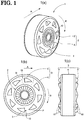
- An aircraft wheel 1 shown in FIGS. 1(a) to 1(c) is constructed by mounting an aircraft tire 3 to a wheel 2 and rotates during a landing roll in a direction of arrow R in the drawings with respect to an aircraft flight direction of arrow A in the drawings.
- the aircraft tire 3 includes a tire body 4 that constitutes an outer peripheral part of the wheel 1, and a plurality of protrusions 5 which are formed integrally with the tire body 4 on a side of the tire body 4 and arranged circumferentially at a predetermined pitch for receiving flight wind pressure (indicated by arrow P in FIG. 1(b) ).
- the wheel 1 can be rotated ahead of touchdown in the direction (of arrow R) in which wheel 1 rotates during the landing roll.
- Each protrusion 5 has, at its base end which is rear in the rotating direction of the wheel 1, a semicircular wind pressure receiving face 10 for receiving the flight wind pressure.
- the protrusion 5 has such a streamline shape that it narrows to taper toward its leading end while its protruding height relative to the side of the tire body 4 reduces as the protrusion 5 extends from the wind pressure receiving face 10 in the rotating direction of wheel 1.
- Such a streamline shape does not cause air turbulence and can prevent abnormal sound. It is to be noted that the streamline shape can appropriately be made longer or shorter than the one shown in this embodiment.
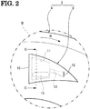
- a hollow part 11 is formed inside the protrusion 5 in an area between the wind pressure receiving face 10 and a middle position of the protrusion 5 along the rotating direction of the wheel 1.
- This hollow part 11 is a virtually semicylindrical space having a required expansion in a radial direction of the tire body 4 as well as along the protruding height relative to the side of the tire body 4.
- the protrusion 5 has a slit 12 formed near the leading end of the protrusion 5 along the rotating direction of the wheel 1, and a weight insertion passage 13 is formed as a connection between the slit 12 and the hollow part 11.
- the weight insertion passage 13 is closed due to elastic restoring force of the protrusion 5 or is in a constricted state inhibiting passage of the weight 15.
- the weight 15 can be inserted into the hollow part 11 by pressing the leading end of the weight 15 against the slit 12 to widen the slit 12, pressing the weight 15 from the slit 12 into the weight insertion passage 13 against the elastic restoring force of the protrusion 5 and then pressing the weight 15 further to expand the weight insertion passage 13.
- the weight insertion passage 13 is closed by the elastic restoring force of the protrusion 5 or is constricted enough to inhibit the passage of the weight 15, so that the weight 15 does not leave the hollow part 11.
- an actual rotating speed V of the wheel 1 ahead of the touchdown (hereinafter referred to as an actual rotating speed V) is lower than a rotating speed V A (hereinafter referred to as a target rotating speed V A ) which is consistent with a flying speed of the aircraft making the touchdown (for example, about 250 km/h)
- the weight 15 inside the hollow part 11 of the protrusion 5 is in a radially inward position indicated by a radius r 1 of FIG. 3(a) that extends from the center of the wheel 1.
- a protruding height H of the protrusion 5 is equal to an initial height H 0
- a pressure receiving area S of the wind pressure receiving face 10 is equal to an initial area S 0 .
- the weight 15 inside the hollow part 11 moves to a radially outward position indicated by a radius r 2 of FIG. 3(b) that extends from the wheel center.
- the protruding height H of the protrusion 5 is still equal to the initial height H 0
- the pressure receiving area S of the wind pressure receiving face 10 is still equal to the initial area S 0 .
- the protruding height H of the protrusion 5 is reduced from the initial height H 0 through a height H 1 to a height H 2 , while the pressure receiving area S of the wind pressure receiving face 10 is reduced from the initial area S 0 to an area S 2 via an area S 1 .
- the wheel 1 is rotated ahead of the touchdown in the direction in which the wheel 1 rotates during the landing roll, so that pressurized friction between a runway and the tire can be reduced substantially during the landing of the aircraft, thereby allowing suppression of rubber tire wear which occurs during the landing.
- the flight wind pressure receiving area S of the wind pressure receiving face 10 remains as the initial area S 0 , and the wheel 1 gains speed through the action of the flight wind pressure to reach the target rotating speed V A before the touchdown.
- the flight wind pressure receiving area S of the wind pressure receiving face 10 reduces from the initial area S 0 to the area S 1 and then to the area S 2 accordingly, whereby the acceleration of the wheel 1 is reduced, and the actual rotating speed V decreases toward the target rotating speed V A due to mechanical frictional resistance of the wheel 1 or the like.
- the centrifugal force applied to the weight 15 decreases, whereby the protrusion 5 returns from its deformed state to its original shape.
- the pressure receiving area S of the wind pressure receiving face 10 returned to the initial area S 0 , the wheel 1 accelerates again through the accelerating action of the flight wind pressure, thus increasing its speed toward the target rotating speed V A again.
- the rotating speed of the wheel 1 is brought close to the rotating speed which is consistent with the flying speed of the aircraft making the touchdown (i.e., the target rotating speed V A ), while repeating its acceleration and deceleration with the target rotating speed V A being in between, thereby reducing a rotating speed difference (V-V A ) between the actual rotating speed V and the target rotating speed V A . Consequently, shocks that accelerate or decelerate the aircraft at the touchdown can be suppressed.
- the weight 15 inserted into the hollow part 11 is a solid lump
- the invention is not limited to this, and the weight may instead be in the form of liquid, gel or granules (not shown) to be inserted into the hollow part 11 of the protrusion 5.
- the wind pressure receiving face 10 has the semicircular shape.
- the invention is not limited to this.
- An arbitrary shape such as a triangular shape shown in FIG. 4(b) or a quadrilateral (or trapezoidal) shape shown in FIG. 4(c) can be adopted instead as long as the shape can receive the flight wind pressure.
- the wind pressure receiving face 10 shown in the above embodiment is a plane surface rising at a right angle from the side of the tire body 4, thus serving as a plane perpendicular to the flight wind pressure.
- the wind pressure receiving face 10 may be curved toward the rotating direction of the wheel 1 so as to receive the flight wind pressure more effectively and furthermore, may slant toward the rotating direction of the wheel 1 as shown in FIG. 4(d), 4(e) or 4(f) to form an obtuse angle with respect to the side of the tire body 4 for the purpose of improving aerodynamic flow of flight wind.
- the protrusion having the streamline shape has been adopted.
- the invention is not limited to this, and a block-type protrusion shaped like a square pole (see FIG. 4(g) ), a triangle pole (see FIG. 4(h) ), a hemisphere or hemiellipsoid (see FIG. 4(i) ), a semicylinder (see FIG. 4(j) ) or a triangular plate (see FIG. 4(k) ) can be adopted instead.
- a whirling airflow at a place indicated by arrow D in the drawing, and which is located downstream of the rotating direction of the wheel 1, allows the rotating speed V of the wheel 1 to reach the target rotating speed V A faster.
- the respective wind pressure receiving faces 10 of block-type protrusions 5G to 5K may be curved toward the rotating direction of the wheel 1 and may each slant to form an obtuse angle with respect to the side of the tire body 4.
- An aircraft tire according to the present invention has the characteristics of being capable of suppressing rubber tire wear during landing and shocks that accelerate or decelerate an aircraft at touchdown and therefore, is suitable for use as a wheel tire for an aircraft which lands at a high flying speed.
Landscapes
- Engineering & Computer Science (AREA)
- Mechanical Engineering (AREA)
- Aviation & Aerospace Engineering (AREA)
- Tires In General (AREA)
Claims (1)
- Pneu d'aéronef (3) comprenant :une saillie (5) pour recevoir l'air de vol, prévue sur un côté d'un corps de pneu (4) qui constitue une partie périphérique externe d'une roue d'aéronef (1), la roue d'aéronef (1) étant faite pour tourner avant l'atterrissage dans une direction (R) dans laquelle la roue (1) tourne pendant le roulage d'atterrissage par l'action de la pression d'air de vol reçue par la saillie (5),caractérisé en ce que :la saillie (5) a une structure creuse (11) dans laquelle un poids (15) est inséré et la saillie (5) est déformée par la force centrifuge appliquée sur le poids (15) en association avec un mouvement de rotation de la roue (1) pour modifier une zone de réception de pression d'air de vol (S) de la saillie (5) de sorte que l'accélération d'une vitesse de rotation de la roue (1) avant l'atterrissage augmente ou diminue.
Applications Claiming Priority (1)
| Application Number | Priority Date | Filing Date | Title |
|---|---|---|---|
| JP2014171669A JP5763818B1 (ja) | 2014-08-26 | 2014-08-26 | 航空機用タイヤ |
Publications (2)
| Publication Number | Publication Date |
|---|---|
| EP2990331A1 EP2990331A1 (fr) | 2016-03-02 |
| EP2990331B1 true EP2990331B1 (fr) | 2018-12-12 |
Family
ID=53783581
Family Applications (1)
| Application Number | Title | Priority Date | Filing Date |
|---|---|---|---|
| EP15179252.0A Active EP2990331B1 (fr) | 2014-08-26 | 2015-07-31 | Pneu d'aéronef |
Country Status (5)
| Country | Link |
|---|---|
| US (1) | US9731817B2 (fr) |
| EP (1) | EP2990331B1 (fr) |
| JP (1) | JP5763818B1 (fr) |
| CN (1) | CN105383686B (fr) |
| CA (1) | CA2898699C (fr) |
Families Citing this family (9)
| Publication number | Priority date | Publication date | Assignee | Title |
|---|---|---|---|---|
| CN105966604A (zh) * | 2016-04-23 | 2016-09-28 | 赵东南 | 一种飞机防磨损轮胎技术 |
| US20170361925A1 (en) * | 2016-06-15 | 2017-12-21 | Wei-Lin Pao | Auxiliary rotating structure and tire assembly therewith |
| JP6219465B1 (ja) | 2016-08-10 | 2017-10-25 | 大東プレス工業株式会社 | 航空機用タイヤ |
| US11260967B1 (en) * | 2017-12-11 | 2022-03-01 | James Robert Davis | No/low skid device |
| JP6976833B2 (ja) * | 2017-12-14 | 2021-12-08 | 株式会社ブリヂストン | 摩耗量予測方法、摩耗量予測装置、及び摩耗量予測プログラム |
| JP7068014B2 (ja) * | 2018-04-11 | 2022-05-16 | Toyo Tire株式会社 | 空気入りタイヤ |
| FR3094271B1 (fr) * | 2019-03-29 | 2021-07-30 | Michelin & Cie | Pneumatique pour véhicule agricole comprenant une bande de roulement |
| KR102730060B1 (ko) * | 2019-04-18 | 2024-11-13 | 한국타이어앤테크놀로지 주식회사 | 공기입 타이어 |
| CN111731473A (zh) * | 2020-06-28 | 2020-10-02 | 杨奥 | 一种飞机起落架机轮同步装置 |
Family Cites Families (19)
| Publication number | Priority date | Publication date | Assignee | Title |
|---|---|---|---|---|
| US1833019A (en) * | 1929-11-01 | 1931-11-24 | Morgan & Wright | Airplane tire |
| GB562651A (en) * | 1942-12-01 | 1944-07-11 | Arthur Herbert Clark | Improvements in or relating to aircraft landing gear |
| JPS5135903A (fr) * | 1974-09-18 | 1976-03-26 | Ihei Saito | |
| DE2613486A1 (de) * | 1976-03-30 | 1977-10-13 | Albert Schneider | Windkappen an flugzeugreifen |
| GB2080217A (en) * | 1980-07-26 | 1982-02-03 | Brookes Rex Harward | Improvements in or relating to aircraft undercarriage wheels |
| JPH061196U (ja) * | 1991-11-01 | 1994-01-11 | 一 木村 | 飛行機用車輪 |
| JPH05178290A (ja) * | 1992-01-06 | 1993-07-20 | Takeshi Kondo | 航空機用タイヤ |
| JPH0731600U (ja) * | 1993-11-24 | 1995-06-13 | 猛 山本 | 風車の羽根を付けた航空機用の車輪 |
| JPH09254892A (ja) | 1996-03-21 | 1997-09-30 | U Giken Kogyo Kk | 飛行機用車輪 |
| GB2352431A (en) * | 1999-07-27 | 2001-01-31 | Norman Evans | Aircraft tyre air scoops for rotating undercarriage wheel |
| CN2484258Y (zh) * | 2001-02-19 | 2002-04-03 | 张淑礼 | 侧面带翼片的航空轮胎 |
| CN2468898Y (zh) * | 2001-03-29 | 2002-01-02 | 韩保禄 | 飞机轮胎 |
| JP2004058978A (ja) * | 2002-07-29 | 2004-02-26 | Yukitaka Urasato | 航空機着陸時のタイヤと滑走路との摩擦及びショック等を軽減するため風車のような羽根を取り付けた航空機用タイヤ及びリム |
| DE10315813A1 (de) * | 2003-04-07 | 2004-11-11 | Behnke, Hans-Hürgen, Dipl.-Ing. | Flugzeugreifen mit Windfangelementen und optional Teilabdeckung um diesen in Rotation zu versetzen |
| KR20030076556A (ko) * | 2003-09-15 | 2003-09-26 | 이두원 | 항공기 착륙바퀴 회전장치. |
| WO2007114803A1 (fr) * | 2006-03-30 | 2007-10-11 | University Of Miami | Roues de train d'atterrissage dotees de profiles aerodynamiques montes lateralement |
| JP2008037138A (ja) * | 2006-08-01 | 2008-02-21 | Yokohama Rubber Co Ltd:The | 空気入りタイヤ |
| RO127093A2 (ro) * | 2010-08-05 | 2012-02-28 | Ioan Negru | Anvelopă pentru voleţi de avion şi navete spaţiale |
| JP2013230801A (ja) * | 2012-05-01 | 2013-11-14 | Bridgestone Corp | タイヤ |
-
2014
- 2014-08-26 JP JP2014171669A patent/JP5763818B1/ja active Active
-
2015
- 2015-07-28 CA CA2898699A patent/CA2898699C/fr active Active
- 2015-07-28 US US14/811,226 patent/US9731817B2/en active Active
- 2015-07-31 EP EP15179252.0A patent/EP2990331B1/fr active Active
- 2015-08-24 CN CN201510524083.9A patent/CN105383686B/zh active Active
Non-Patent Citations (1)
| Title |
|---|
| None * |
Also Published As
| Publication number | Publication date |
|---|---|
| US9731817B2 (en) | 2017-08-15 |
| CN105383686B (zh) | 2018-11-13 |
| CA2898699C (fr) | 2018-06-05 |
| EP2990331A1 (fr) | 2016-03-02 |
| CN105383686A (zh) | 2016-03-09 |
| JP2016043881A (ja) | 2016-04-04 |
| CA2898699A1 (fr) | 2016-02-26 |
| US20160059955A1 (en) | 2016-03-03 |
| JP5763818B1 (ja) | 2015-08-12 |
Similar Documents
| Publication | Publication Date | Title |
|---|---|---|
| US9731817B2 (en) | Aircraft tire | |
| US20160046372A1 (en) | Rocket Morphing Aerial Vehicle | |
| KR101822386B1 (ko) | 드론의 무선 충전 시스템 | |
| WO2016209350A3 (fr) | Carénage de train d'atterrissage à surfaces aérodynamiques pour avion à décollage vertical | |
| EP3281868B1 (fr) | Pneu d'aéronef | |
| US4129984A (en) | Gas turbine engine with anti-icing facility | |
| US5070791A (en) | Projectile tail cone | |
| CN205060009U (zh) | 一种机臂轴可转动的平行轴四轴飞行器 | |
| US10520290B2 (en) | Projectile | |
| US10646804B2 (en) | System and method for conditioning flow of a wet gas stream | |
| CN110514072B (zh) | 一种保证跨水空介质导弹安全入水的组合减速装置及方法 | |
| US2130881A (en) | Wheel | |
| JP2008254628A (ja) | 航空機におけるタイヤ磨耗軽減装置 | |
| US2398145A (en) | Airplane landing gear | |
| US20170361925A1 (en) | Auxiliary rotating structure and tire assembly therewith | |
| RU2110444C1 (ru) | Фюзеляж летательного аппарата | |
| US2922365A (en) | Aerial missile | |
| WO2019021266A1 (fr) | Empennage | |
| WO2014122464A1 (fr) | Ensemble de lancement pour le lancement d'armes à partir d'un véhicule aérien | |
| KR101581251B1 (ko) | 비행체 자세제어장치 및 이를 구비하는 비행체 | |
| EP3184323B1 (fr) | Manchon d'essieu de frein | |
| WO2007114803A1 (fr) | Roues de train d'atterrissage dotees de profiles aerodynamiques montes lateralement | |
| WO2017146579A1 (fr) | Avion équipé d'un empennage propulseur à surfaces de commande intégrées monté sur le fuselage arrière | |
| KR20220049849A (ko) | 회전날개 어셈블리 | |
| US20190241249A1 (en) | Wings for flying objects (variants) |
Legal Events
| Date | Code | Title | Description |
|---|---|---|---|
| PUAI | Public reference made under article 153(3) epc to a published international application that has entered the european phase |
Free format text: ORIGINAL CODE: 0009012 |
|
| AK | Designated contracting states |
Kind code of ref document: A1 Designated state(s): AL AT BE BG CH CY CZ DE DK EE ES FI FR GB GR HR HU IE IS IT LI LT LU LV MC MK MT NL NO PL PT RO RS SE SI SK SM TR |
|
| AX | Request for extension of the european patent |
Extension state: BA ME |
|
| 17P | Request for examination filed |
Effective date: 20160831 |
|
| RBV | Designated contracting states (corrected) |
Designated state(s): AL AT BE BG CH CY CZ DE DK EE ES FI FR GB GR HR HU IE IS IT LI LT LU LV MC MK MT NL NO PL PT RO RS SE SI SK SM TR |
|
| GRAP | Despatch of communication of intention to grant a patent |
Free format text: ORIGINAL CODE: EPIDOSNIGR1 |
|
| STAA | Information on the status of an ep patent application or granted ep patent |
Free format text: STATUS: GRANT OF PATENT IS INTENDED |
|
| INTG | Intention to grant announced |
Effective date: 20180703 |
|
| GRAS | Grant fee paid |
Free format text: ORIGINAL CODE: EPIDOSNIGR3 |
|
| GRAA | (expected) grant |
Free format text: ORIGINAL CODE: 0009210 |
|
| STAA | Information on the status of an ep patent application or granted ep patent |
Free format text: STATUS: THE PATENT HAS BEEN GRANTED |
|
| AK | Designated contracting states |
Kind code of ref document: B1 Designated state(s): AL AT BE BG CH CY CZ DE DK EE ES FI FR GB GR HR HU IE IS IT LI LT LU LV MC MK MT NL NO PL PT RO RS SE SI SK SM TR |
|
| REG | Reference to a national code |
Ref country code: GB Ref legal event code: FG4D |
|
| REG | Reference to a national code |
Ref country code: CH Ref legal event code: EP |
|
| REG | Reference to a national code |
Ref country code: AT Ref legal event code: REF Ref document number: 1075634 Country of ref document: AT Kind code of ref document: T Effective date: 20181215 |
|
| REG | Reference to a national code |
Ref country code: DE Ref legal event code: R096 Ref document number: 602015021147 Country of ref document: DE |
|
| REG | Reference to a national code |
Ref country code: IE Ref legal event code: FG4D |
|
| REG | Reference to a national code |
Ref country code: NL Ref legal event code: MP Effective date: 20181212 |
|
| REG | Reference to a national code |
Ref country code: LT Ref legal event code: MG4D |
|
| PG25 | Lapsed in a contracting state [announced via postgrant information from national office to epo] |
Ref country code: FI Free format text: LAPSE BECAUSE OF FAILURE TO SUBMIT A TRANSLATION OF THE DESCRIPTION OR TO PAY THE FEE WITHIN THE PRESCRIBED TIME-LIMIT Effective date: 20181212 Ref country code: LT Free format text: LAPSE BECAUSE OF FAILURE TO SUBMIT A TRANSLATION OF THE DESCRIPTION OR TO PAY THE FEE WITHIN THE PRESCRIBED TIME-LIMIT Effective date: 20181212 Ref country code: HR Free format text: LAPSE BECAUSE OF FAILURE TO SUBMIT A TRANSLATION OF THE DESCRIPTION OR TO PAY THE FEE WITHIN THE PRESCRIBED TIME-LIMIT Effective date: 20181212 Ref country code: LV Free format text: LAPSE BECAUSE OF FAILURE TO SUBMIT A TRANSLATION OF THE DESCRIPTION OR TO PAY THE FEE WITHIN THE PRESCRIBED TIME-LIMIT Effective date: 20181212 Ref country code: NO Free format text: LAPSE BECAUSE OF FAILURE TO SUBMIT A TRANSLATION OF THE DESCRIPTION OR TO PAY THE FEE WITHIN THE PRESCRIBED TIME-LIMIT Effective date: 20190312 Ref country code: ES Free format text: LAPSE BECAUSE OF FAILURE TO SUBMIT A TRANSLATION OF THE DESCRIPTION OR TO PAY THE FEE WITHIN THE PRESCRIBED TIME-LIMIT Effective date: 20181212 Ref country code: BG Free format text: LAPSE BECAUSE OF FAILURE TO SUBMIT A TRANSLATION OF THE DESCRIPTION OR TO PAY THE FEE WITHIN THE PRESCRIBED TIME-LIMIT Effective date: 20190312 |
|
| REG | Reference to a national code |
Ref country code: AT Ref legal event code: MK05 Ref document number: 1075634 Country of ref document: AT Kind code of ref document: T Effective date: 20181212 |
|
| PG25 | Lapsed in a contracting state [announced via postgrant information from national office to epo] |
Ref country code: AL Free format text: LAPSE BECAUSE OF FAILURE TO SUBMIT A TRANSLATION OF THE DESCRIPTION OR TO PAY THE FEE WITHIN THE PRESCRIBED TIME-LIMIT Effective date: 20181212 Ref country code: SE Free format text: LAPSE BECAUSE OF FAILURE TO SUBMIT A TRANSLATION OF THE DESCRIPTION OR TO PAY THE FEE WITHIN THE PRESCRIBED TIME-LIMIT Effective date: 20181212 Ref country code: GR Free format text: LAPSE BECAUSE OF FAILURE TO SUBMIT A TRANSLATION OF THE DESCRIPTION OR TO PAY THE FEE WITHIN THE PRESCRIBED TIME-LIMIT Effective date: 20190313 Ref country code: RS Free format text: LAPSE BECAUSE OF FAILURE TO SUBMIT A TRANSLATION OF THE DESCRIPTION OR TO PAY THE FEE WITHIN THE PRESCRIBED TIME-LIMIT Effective date: 20181212 |
|
| PG25 | Lapsed in a contracting state [announced via postgrant information from national office to epo] |
Ref country code: NL Free format text: LAPSE BECAUSE OF FAILURE TO SUBMIT A TRANSLATION OF THE DESCRIPTION OR TO PAY THE FEE WITHIN THE PRESCRIBED TIME-LIMIT Effective date: 20181212 |
|
| PG25 | Lapsed in a contracting state [announced via postgrant information from national office to epo] |
Ref country code: CZ Free format text: LAPSE BECAUSE OF FAILURE TO SUBMIT A TRANSLATION OF THE DESCRIPTION OR TO PAY THE FEE WITHIN THE PRESCRIBED TIME-LIMIT Effective date: 20181212 Ref country code: PT Free format text: LAPSE BECAUSE OF FAILURE TO SUBMIT A TRANSLATION OF THE DESCRIPTION OR TO PAY THE FEE WITHIN THE PRESCRIBED TIME-LIMIT Effective date: 20190412 Ref country code: PL Free format text: LAPSE BECAUSE OF FAILURE TO SUBMIT A TRANSLATION OF THE DESCRIPTION OR TO PAY THE FEE WITHIN THE PRESCRIBED TIME-LIMIT Effective date: 20181212 Ref country code: IT Free format text: LAPSE BECAUSE OF FAILURE TO SUBMIT A TRANSLATION OF THE DESCRIPTION OR TO PAY THE FEE WITHIN THE PRESCRIBED TIME-LIMIT Effective date: 20181212 |
|
| PG25 | Lapsed in a contracting state [announced via postgrant information from national office to epo] |
Ref country code: SM Free format text: LAPSE BECAUSE OF FAILURE TO SUBMIT A TRANSLATION OF THE DESCRIPTION OR TO PAY THE FEE WITHIN THE PRESCRIBED TIME-LIMIT Effective date: 20181212 Ref country code: EE Free format text: LAPSE BECAUSE OF FAILURE TO SUBMIT A TRANSLATION OF THE DESCRIPTION OR TO PAY THE FEE WITHIN THE PRESCRIBED TIME-LIMIT Effective date: 20181212 Ref country code: IS Free format text: LAPSE BECAUSE OF FAILURE TO SUBMIT A TRANSLATION OF THE DESCRIPTION OR TO PAY THE FEE WITHIN THE PRESCRIBED TIME-LIMIT Effective date: 20190412 Ref country code: RO Free format text: LAPSE BECAUSE OF FAILURE TO SUBMIT A TRANSLATION OF THE DESCRIPTION OR TO PAY THE FEE WITHIN THE PRESCRIBED TIME-LIMIT Effective date: 20181212 Ref country code: SK Free format text: LAPSE BECAUSE OF FAILURE TO SUBMIT A TRANSLATION OF THE DESCRIPTION OR TO PAY THE FEE WITHIN THE PRESCRIBED TIME-LIMIT Effective date: 20181212 |
|
| REG | Reference to a national code |
Ref country code: DE Ref legal event code: R097 Ref document number: 602015021147 Country of ref document: DE |
|
| PLBE | No opposition filed within time limit |
Free format text: ORIGINAL CODE: 0009261 |
|
| STAA | Information on the status of an ep patent application or granted ep patent |
Free format text: STATUS: NO OPPOSITION FILED WITHIN TIME LIMIT |
|
| PG25 | Lapsed in a contracting state [announced via postgrant information from national office to epo] |
Ref country code: DK Free format text: LAPSE BECAUSE OF FAILURE TO SUBMIT A TRANSLATION OF THE DESCRIPTION OR TO PAY THE FEE WITHIN THE PRESCRIBED TIME-LIMIT Effective date: 20181212 Ref country code: AT Free format text: LAPSE BECAUSE OF FAILURE TO SUBMIT A TRANSLATION OF THE DESCRIPTION OR TO PAY THE FEE WITHIN THE PRESCRIBED TIME-LIMIT Effective date: 20181212 Ref country code: SI Free format text: LAPSE BECAUSE OF FAILURE TO SUBMIT A TRANSLATION OF THE DESCRIPTION OR TO PAY THE FEE WITHIN THE PRESCRIBED TIME-LIMIT Effective date: 20181212 |
|
| 26N | No opposition filed |
Effective date: 20190913 |
|
| PG25 | Lapsed in a contracting state [announced via postgrant information from national office to epo] |
Ref country code: MC Free format text: LAPSE BECAUSE OF FAILURE TO SUBMIT A TRANSLATION OF THE DESCRIPTION OR TO PAY THE FEE WITHIN THE PRESCRIBED TIME-LIMIT Effective date: 20181212 |
|
| REG | Reference to a national code |
Ref country code: CH Ref legal event code: PL |
|
| PG25 | Lapsed in a contracting state [announced via postgrant information from national office to epo] |
Ref country code: TR Free format text: LAPSE BECAUSE OF FAILURE TO SUBMIT A TRANSLATION OF THE DESCRIPTION OR TO PAY THE FEE WITHIN THE PRESCRIBED TIME-LIMIT Effective date: 20181212 |
|
| REG | Reference to a national code |
Ref country code: BE Ref legal event code: MM Effective date: 20190731 |
|
| PG25 | Lapsed in a contracting state [announced via postgrant information from national office to epo] |
Ref country code: LU Free format text: LAPSE BECAUSE OF NON-PAYMENT OF DUE FEES Effective date: 20190731 Ref country code: CH Free format text: LAPSE BECAUSE OF NON-PAYMENT OF DUE FEES Effective date: 20190731 Ref country code: LI Free format text: LAPSE BECAUSE OF NON-PAYMENT OF DUE FEES Effective date: 20190731 Ref country code: BE Free format text: LAPSE BECAUSE OF NON-PAYMENT OF DUE FEES Effective date: 20190731 |
|
| PG25 | Lapsed in a contracting state [announced via postgrant information from national office to epo] |
Ref country code: IE Free format text: LAPSE BECAUSE OF NON-PAYMENT OF DUE FEES Effective date: 20190731 |
|
| PG25 | Lapsed in a contracting state [announced via postgrant information from national office to epo] |
Ref country code: CY Free format text: LAPSE BECAUSE OF FAILURE TO SUBMIT A TRANSLATION OF THE DESCRIPTION OR TO PAY THE FEE WITHIN THE PRESCRIBED TIME-LIMIT Effective date: 20181212 |
|
| PG25 | Lapsed in a contracting state [announced via postgrant information from national office to epo] |
Ref country code: HU Free format text: LAPSE BECAUSE OF FAILURE TO SUBMIT A TRANSLATION OF THE DESCRIPTION OR TO PAY THE FEE WITHIN THE PRESCRIBED TIME-LIMIT; INVALID AB INITIO Effective date: 20150731 Ref country code: MT Free format text: LAPSE BECAUSE OF FAILURE TO SUBMIT A TRANSLATION OF THE DESCRIPTION OR TO PAY THE FEE WITHIN THE PRESCRIBED TIME-LIMIT Effective date: 20181212 |
|
| PG25 | Lapsed in a contracting state [announced via postgrant information from national office to epo] |
Ref country code: MK Free format text: LAPSE BECAUSE OF FAILURE TO SUBMIT A TRANSLATION OF THE DESCRIPTION OR TO PAY THE FEE WITHIN THE PRESCRIBED TIME-LIMIT Effective date: 20181212 |
|
| REG | Reference to a national code |
Ref country code: FR Ref legal event code: PLFP Year of fee payment: 8 |
|
| PGFP | Annual fee paid to national office [announced via postgrant information from national office to epo] |
Ref country code: DE Payment date: 20250702 Year of fee payment: 11 |
|
| PGFP | Annual fee paid to national office [announced via postgrant information from national office to epo] |
Ref country code: GB Payment date: 20250724 Year of fee payment: 11 |
|
| PGFP | Annual fee paid to national office [announced via postgrant information from national office to epo] |
Ref country code: FR Payment date: 20250723 Year of fee payment: 11 |