EP2991925B1 - Commutateur de commande pour une commande d'une machine, en particulier une télécommande d'une grue sans fil, portable et actionnable à la main - Google Patents
Commutateur de commande pour une commande d'une machine, en particulier une télécommande d'une grue sans fil, portable et actionnable à la main Download PDFInfo
- Publication number
- EP2991925B1 EP2991925B1 EP14771886.0A EP14771886A EP2991925B1 EP 2991925 B1 EP2991925 B1 EP 2991925B1 EP 14771886 A EP14771886 A EP 14771886A EP 2991925 B1 EP2991925 B1 EP 2991925B1
- Authority
- EP
- European Patent Office
- Prior art keywords
- sensor
- control switch
- operator
- housing
- sensors
- Prior art date
- Legal status (The legal status is an assumption and is not a legal conclusion. Google has not performed a legal analysis and makes no representation as to the accuracy of the status listed.)
- Active
Links
Images

Classifications
-
- B—PERFORMING OPERATIONS; TRANSPORTING
- B66—HOISTING; LIFTING; HAULING
- B66C—CRANES; LOAD-ENGAGING ELEMENTS OR DEVICES FOR CRANES, CAPSTANS, WINCHES, OR TACKLES
- B66C13/00—Other constructional features or details
- B66C13/18—Control systems or devices
- B66C13/40—Applications of devices for transmitting control pulses; Applications of remote control devices
-
- G—PHYSICS
- G08—SIGNALLING
- G08C—TRANSMISSION SYSTEMS FOR MEASURED VALUES, CONTROL OR SIMILAR SIGNALS
- G08C17/00—Arrangements for transmitting signals characterised by the use of a wireless electrical link
- G08C17/02—Arrangements for transmitting signals characterised by the use of a wireless electrical link using a radio link
Definitions
- the invention relates to a control switch for operating a machine, in particular a wireless, portable and manually operable remote control for a crane, with a detection device, via which an operator can be detected, and with a safety circuit, via which the control switch is activated upon detection of an operator and is disabled when not detecting an operator.
- the German patent application DE 10 2009 051 819 A1 discloses a suspension switch for a crane whose controls are activated and deactivated via a safety circuit.
- the security circuit comprises an RFID reader which is arranged in the hanging switch, and an RFID transponder which is carried in the form of a bracelet by an operator authorized to operate the crane.
- the RFID reader has a signal strength with a short range in the range of about 20 cm to 30 cm.
- the safety circuit ensures that the controls of the pendant switch are activated only as long and thus the crane is only as long as operable as an authorized operator is in sufficient proximity to the control switch, ie the RIFD transponder in the reception area of the RFID reader , As soon as the operator or their RFID transponder moves too far out of the reception area of the RFID reader, the safety circuit deactivates the operating elements of the pendant switch.
- a wireless control switch for a crane which has a micro-joystick and a tilt sensor as controls.
- a so-called deadman button is arranged, which must be pressed with the thumb, in order to be able to work with the micro joystick. This is intended to prevent unintentional triggering of crane functions.
- the tilt sensor in the control switch is activated by a release button on the underside of the control switch pressed by a forefinger. As soon as the release button is released, the tilt sensor is deactivated.
- the inclination sensor can be used to initiate lifting or lowering movements as well as traveling movements of a crane trolley.
- a deadman circuit for a circular saw known.
- the circular saw has a trolley which can be moved by means of a feed drive.
- the feed drive can be controlled via a rotary handle.
- the dead man's circuit is provided in the form of a capacitive, inductive, mechanical and / or electrical sensor in the region of the rotary handle. This ensures that when a touch of the rotary handle by an operator, the presence of the operator is detected, which triggers a release of the feed drive by the dead man's circuit.
- the invention has for its object to provide a control switch for operation of a crane, in particular a wireless, portable and hand-operated remote control, which provides an improved safety circuit for activating and deactivating the control switch.
- a control switch for operating a crane in particular a wireless, portable and hand-operated remote control, with a detection device, via which an operator is detectable, and with a gripping area for an operator having housing and with a safety circuit, via which the control switch can be activated upon detection of an operator and can be deactivated when not detecting an operator
- the detection device comprises at least one sensor which detects a hand holding the control switch in the gripping area of the operator in a near field
- the detection device at least one other Includes sensor that detects a use of the control switch.
- the at least two sensors together with the safety circuit take over the deadman function and continuously detect the presence of the operator's hand in the gripping area of the housing of the control switch or a use of the control switch. In ergonomically speaking, this leads to an improvement, since the operator does not have to actively operate a deadman button. In addition, unwanted interruptions in the operation are avoided because the activation of the control switch is not dependent on the permanent holding down a deadman button, but only on the fact that an operator holds the control switch in his hand. Also, the operation of the control switch changes or is not limited compared to known models, since the sensors are not perceived by the operator. Furthermore, these sensors are robust, so that a suitability for the operation of a crane is given. The use of two sensors increases the likelihood that only one operator hand or operator using the controller will cause the activation.
- a hand recognition could also take place indirectly in connection with a wireless solution and a transponder located on the hand or the body and to be recognized.
- the at least one sensor and the further sensor are connected to a logic circuit which sends an activation signal to the safety circuit when the near field sensor and the further sensor each detect an operator or detect a use of the control switch. This increases the safety with respect to the detection and the function of the sensors
- the near field starting from the gripping area, extends a maximum of 3 mm, preferably a maximum of 2 mm. This reliably ensures that inadvertent operation of the control switch can not take place. Also, the desired deadman function is achieved by this small close range.
- the at least one first sensor is arranged in the interior of a housing of the control switch such that a hand of the operator holding the control switch can be recognized by the sensor.
- the sensors are thus integrated in the housing and are not perceived by the user and do not interfere with the operation of the control switch.
- At least one further sensor is arranged in the interior of the housing, which sensor is designed as a near-field sensor, acceleration sensor, as an optical sensor or as an inclination sensor. An activation of the control switch is then only if in addition to the detection by the capacitive sensor and a detection by the other sensor is present.
- the second sensor is designed as a near-field sensor and the first sensor and the second sensor are arranged at a distance from each other in the housing. The spacing increases the likelihood that only one operator's hand will trigger the activation.
- a second near-field sensor and a third near-field sensor are arranged in the interior of the housing of the control switch such that a hand holding the control switch of the operator of the second sensor or the third sensor in addition to the first Sensor is recognizable.
- the control switch can also be placed on an object without an activation takes place.
- the at least one first near field sensor is a capacitive sensor or a radio sensor.
- the first, second and third sensors are designed as capacitive sensors, each comprising a first, second and third electrode, the first electrode, the second electrode and the third electrode at a distance, preferably orthogonal in different spatial Layers are arranged to each other in the housing.
- the spacing and, where appropriate, the spatial arrangement of the electrodes increases the likelihood that only one operator's hand will cause the activation.
- first electrode in the region of a bottom of the housing, the second electrode in the region of a left longitudinal side of the housing and the third electrode in the region of a right longitudinal side of the housing is arranged. In order to allows both right- and left-handed operation.
- the near field sensor and the further sensor are connected to a logic circuit which sends an activation signal to the safety circuit when the near field sensor and the further sensor each detect an operator.
- the first, second and third sensor are connected to a logic circuit that sends an activation signal to the safety circuit when the first sensor and one of the second and third sensors each detect an operator.
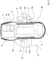
- FIG. 1 shows a plan view of a wireless control switch 1 according to the invention, which is designed as a radio-operated and portable hand control switch.
- the control switch 1 consists in a conventional manner of a substantially cuboidal housing 2 with rounded corners, on the upper side 2a more controls 3 and a display 4 are arranged.
- the shape and dimensions of the control switch 1 are dimensioned so that it fits well on a gripping area 2f of a hand 13 of an operator (see FIG. 2 ) can be surrounded and the controls 3 are easily accessible and operable with the thumb.
- the controls 3 are designed as a single or multi-stage button or mini-joystick and wear in a conventional manner symbols, each corresponding to an operating function for a crane.
- control switch 1 for an indoor crane
- the symbols show the functions lifting, lowering, crab drive right, Katzfahrt left, crane forward, crane movement backwards as well as freely assignable special functions such as operation of a horn.
- the mini-joysticks for example, control the travel movements of crane and cat.
- the display 4 for example, the state of charge of a battery or operating states of the control switch 1 can be displayed.
- By operating one of the controls 3 of the control switch 1 corresponding control signals are generated for the respective operating function and sent wirelessly to the crane and thus triggered the respective control process.
- the housing 2 there is enough space to accommodate unillustrated components such as a rechargeable battery 5, mechanical and electrical parts of the controls 3, and a control circuit 6 for generating, processing, transmitting, and receiving control signals.
- a rechargeable battery 5 for generating, processing, transmitting, and receiving control signals.
- the battery 5 and the control circuit 6 are in the FIG. 2 shown schematically.
- safety circuit 7 is provided to prevent inadvertent operation of the control switch 1.
- the control switch 1 between a safety state and an operating state as needed switchable back and forth.
- the controls 3 - With the exception of the stop button - disabled.
- it can not come to an unintentional operation of the crane, for example, by not deposited or stored on the control switch 1 items or the fall of the control switch.
- FIG. 2 shows a sectional view of the control switch according to FIG. 1 ,
- the housing 2 consists of an upper part and a lower part, so that the FIG. 2 the bowl-shaped lower part with a bottom 2b, a left longitudinal side 2c and a right longitudinal side 2d shows.
- the control circuit 6 and the safety circuit 7 at the upper end of the housing 2 are shown schematically next to the battery 6 at the lower end of the housing 2.
- the safety circuit 7 is divided into a logic part 7a and a monitoring part 7b.
- the monitoring part 7b cyclically checks the correct function of the sensors 8, 9, 10. This monitoring function can also be implemented in the control circuit 6.
- a first sensor 8, second sensor 9 and a third sensor 10 are disposed inside 2e of the housing 2.
- Each of the sensors 8, 9 and 10 is designed as a near-field sensor with a near-field region of a maximum of 3 mm, preferably a maximum of 2 mm. This near field area is located in the gripping area 2f of the control switch 2. By means of such a near field sensor, a hand 13 of an operator can be detected when it is in the near field area.
- Near-field sensors can be sensors with capacitive electrodes or radio antennas.
- the sensors 8, 9 and 10 are formed as touch-sensitive capacitive sensors, each having a flat plate-shaped and rectangular electrodes 8a, 9a and 10a, which are arranged in the longitudinal direction L of the housing 2 in the middle and thus in the gripping area 2f of a control switch 1 embracing hand 13 of an operator.
- the electrodes 8a, 9a and 10a are plate-shaped or rod-shaped.
- the first electrode 8a is aligned with its longitudinal extent in the longitudinal direction L of the housing 2 and arranged on the underside 2b of the housing 2 and thus is the center of a hand of an operator encompassing the control switch 1 opposite. Usually lies in the operation of the control switch 1, this with its bottom 2b in the palm of the operator.
- the palm of his hand is on his hand from the outside on the right longitudinal side 2 d of the control switch 1 at.
- the second electrode 9b is arranged and aligned with its longitudinal extension in the longitudinal direction L of the housing 2.
- the second electrode 9b thus lies opposite the palm of the hand.
- the third electrode 10a is disposed opposite to the second electrode 9b inside on the left longitudinal side 2c of the housing 2 and also aligned with its longitudinal extent in the longitudinal direction L of the housing 2.
- the fingers are only slightly or not from the outside on the left longitudinal side 2c, so that they are not the third sensor 10 opposite.
- the third sensor 10 is thus used when the control switch 1 is held by a left-hander, since then the palm of your hand rests against the left longitudinal side 2c.
- the rectangular electrodes 8a, 9a and 10a are made of a conductive material, preferably copper or a copper alloy.
- the capacitance required for the electrodes 8a, 9a and 10a depends, inter alia, on the size and position of the electrodes 8a, 9a and 10a in the housing 2, the material of the housing 2 and the electrodes 8a, 9a and 10a.
- the plate-like or rod-shaped shape of the electrodes 8a, 9a and 10a it is also conceivable that these to evaporate on the inside of the case.
- the electrodes 8a, 9a and 10a of the sensors 8, 9 and 10 are in this case designed and disposed within the housing 2 of the control switch 1 that a touch on an outside of the housing 2 to the control switch 1 of the sensors 8, 9 and 10 without a direct contact with their electrodes 8a, 9a and 10a leads to a detectable capacitance change and thus also to the detection of an adjacent hand. It is irrelevant whether the hand has direct contact with the housing or the operator wears a glove. In order to be able to output a corresponding output signal in the case of a hand recognition, the sensors 8, 9 and 10 work with a recognition circuit 8b, 9b and 10b (see FIG FIG.
- a quiescent value may change depending on environmental conditions. Since a predetermined change in capacitance leads to an output signal in the sense of a hand recognition, a corresponding adaptation of the associated absolute values takes place.
- the sensors 8, 9 and 10 cooperate with the safety circuit 7 to activate and deactivate the control switch 1 in the manner of a dead man's circuit.
- the detection circuits 8b, 9b and 10b are connected to the safety circuit 7 via first, second and third signal lines 8c, 9c and 10.
- the detection circuits 8b, 9b and 10b are not shown. These can also be arranged together on a circuit board with the safety circuit 7, so that the first, second and third signal lines 8c, 9c and 10c are printed conductors.
- the control switch 1 in particular the bottom 2b and one of the long sides 2c and 2d with an object, which is usually the hand 13 of an operator in contact.
- the control circuit 1 is activated by the safety circuit 7.
- the control switch 1 remains activated only as long as such an applied hand is detected.
- the safety circuit 7 continuously queries the state of the sensors 8, 9 and 10. Accordingly, the safety circuit 2 deactivates the control switch 1, when no operator's hand is detected anymore. This deactivation is usually associated with a locking of the controls 3, so that all crane functions come to a standstill with the exception of the stop button.
- the control switch 1 Since not only touches of one hand, but also touches by any, both electrically conductive and dielectric material can be detected via the sensors 8, 9 and 10, it must be ruled out that the control switch 1 is already activated by merely resting on a workbench, for example becomes. Therefore, the first electrode 8a is offset from the second or third electrode 9a, 10a by approximately 90 degrees, so that they do not lie in a common plane of the housing 2 of the control switch 1.
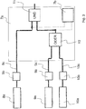
- FIG. 3 shows a schematic diagram of the logic circuit 7a within the safety circuit of the control switch 1.
- the sensors 8, 9 and 10 with their electrodes 8a, 9a and 10a and detection circuits 8b, 9b and 10b interconnected with the target that for Activation of the control switch 1 must reach at least two sensors 8, 9 and 10 in a detection state.
- first, second and third signal lines 8c, 9c and 10c of the sensors 8, 9 and 10 are provided on the output side of their detection circuits 8b, 9b and 10b.
- the logic circuit is designed as a two-channel system, wherein the first electrode 8a is assigned to the bottom 2b of the housing 2 a first channel and the second and third electrode 9a, 10a on the longitudinal sides 2c, 2d of the housing 2 is associated with a second channel.
- the output signals of the first and the second channel are linked via an AND circuit 11, so that the palm and palms of the operator of the sensors 8, 9 and 10 must be recognized for activation of the control switch 1.
- the two opposing sensors 9 and 10 are provided, of which corresponding manner only one of the palm of the operator is detected, is a link via an OR circuit 12 in the second Channel provided.
- the safety circuit 7 activates the control switch 1 only when both channels of the safety circuit 7 detect an applied hand.
- the output signals of the OR circuit 12 and the detection circuit 8b are monitored by the monitoring circuit 7b.
- the logic circuit 7a and / or the monitoring circuit 7b can also by Microcomputer technology can be realized.
- two micro-controllers are then preferably required. Both receive the sensor information and compare the respective output signals. Only if they match the controls 3 are unlocked.
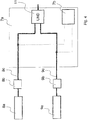
- FIG. 4 shows a substantially the schematic diagram according to FIG. 3 corresponding circuit diagram, so that reference can essentially be made to the preceding description.
- the main difference is that only two sensors 8, 9 are used.
- the first sensor 8 is designed as a capacitive sensor and the second sensor 9 as a tilt sensor.
- the OR circuit 12 can be omitted, since the inclination sensor operates independently of the operation of the control switch 1 by a right or left-handed. Accordingly, the output signals of the two detection circuits 8b and 9b are monitored by the monitoring circuit 7b.
- the present invention is described with reference to a radio controlled control switch 1.
- the invention in an infrared-operated control switch or other wireless methods for data transmission.
- the control switch 1 is designed as a conventional suspension control switch and the control signals are sent via a control line connecting the suspension control switch with the crane.
- the present invention enables operation of machines in general, in the event the control switch is used.
- the sensors 8, 9 and 10 may be formed as an acceleration sensor, as an optical sensor or as a tilt sensor. These sensors can be arranged at any location in or on the housing 2 of the control switch 1.
- the side electrodes 9a and 10a may be replaced by portions of EMC gaskets consisting essentially of an elastic support and an electrically conductive wire mesh.
- the electrodes 8a, 9a and 10a be damped or glued electrodes. These sections then each assume the function of a capacitive sensor.
- the near-field sensor is described as a capacitive sensor with an electrode.
- the near-field sensor can also be designed as a radio sensor with an antenna, which is then arranged in the housing instead of the electrode.
- An RF sensor or radio sensor generally consists of an antenna and an RF module, both of which are arranged in the housing of the control switch and usually adjacent.
- the RF module has a transmitter (transmitter) with which electrical signals are converted into electromagnetic waves and transmitted via the antenna.
- RF modules that can transmit and receive (transceiver).
- the antenna dimensions are matched to the frequency of the electromagnetic waves to be transmitted and received or at the wavelength thereof.
- a transponder in particular RIFD transponder is then arranged, which is then detected.
- the near field sensor can also be designed as an IR transmitting diode and IR receiver diode, which is then arranged in the housing instead of the electrodes or radio sensors.
- IR transmitter diode and IR receiver diode are arranged opposite each other in terms of light barrier, so that the IR light path is interrupted by the operator's hand in order to generate the required signal "handle occupied".
- reflex photoelectric sensors can be used: IR transmitters and IR receivers are not arranged opposite each other but side by side. The operator's hand reflects the IR light as it approaches, so in this case, the "handle busy" signal is generated when the receiver receives the reflected IR light.
- near-field sensors base units of the so-called body-Com technology of Microchip Technology.
- the body-com technology uses bidirectional communication between a base unit that is installed in the housing of the switch and a mobile detection chip that is carried by the operator on the body or in the clothing.
- the signals to be transmitted are capacitively transmitted and received by the base unit and the detection chip, the human body serving as a communication channel.
- This technology implicitly recognizes the hand of an operator as the communication channel is established. For the purposes of the invention, this also means a hand recognition.
- an RFID transponder may also be worn by the operator near his thumb.
Landscapes
- Engineering & Computer Science (AREA)
- Automation & Control Theory (AREA)
- Mechanical Engineering (AREA)
- Computer Networks & Wireless Communication (AREA)
- Physics & Mathematics (AREA)
- General Physics & Mathematics (AREA)
- Switches That Are Operated By Magnetic Or Electric Fields (AREA)
- Control And Safety Of Cranes (AREA)
- Arrangements For Transmission Of Measured Signals (AREA)
Claims (11)
- Commutateur de commande (1) destiné à une commande d'une machine, en particulier d'une télécommande sans fil, portable et actionnable à la main destinée à une grue, comprenant un boîtier (2) pourvu d'une zone de préhension (2f) destinée à un opérateur, un dispositif de détection qui permet de détecter un opérateur, et un circuit de sécurité (7) qui permet d'activer le commutateur de commande (1) lors de la détection d'un opérateur et de le désactiver lors de la non-détection d'un opérateur, caractérisé en ce que le dispositif de détection comprend au moins un capteur (8, 9, 10) qui détecte dans un champ proche une main d'un opérateur qui tient le commutateur de commande (1) dans la zone de préhension (2f) et en ce que le dispositif de détection comprend au moins un autre capteur (9, 10) qui détecte une utilisation du commutateur de commande (1).
- Commutateur de commande (1) selon la revendication 1, caractérisé en ce que l'au moins un capteur (8, 9, 10) et l'autre capteur (9, 10) sont reliés à un circuit logique (7a) qui envoie un signal d'activation au circuit de sécurité (7) lorsque le capteur de champ proche (8) et l'autre capteur (9, 10) détectent chacun un opérateur ou détectent une utilisation du commutateur de commande (1).
- Commutateur de commande (1) selon la revendication 1 ou 2, caractérisé en ce que le champ proche s'accroît au maximum de 3 mm, de préférence au maximum 2 mm, à partir de la zone de préhension (2).
- Commutateur de commande (1) selon l'une des revendications 1 à 3, caractérisé en ce qu'un premier capteur (8) est disposé à l'intérieur (2e) d'un boîtier (2) du commutateur de commande (1) de telle sorte qu'une main de l'opérateur, tenant le commutateur de commande (1), peut être détectée par le premier capteur (8).
- Commutateur de commande (1) selon la revendication 4, caractérisé en ce qu'au moins un deuxième capteur (9, 10) est disposé à l'intérieur (2e) du boîtier (2), lequel capteur est conformé en capteur de champ proche, capteur d'accélération, capteur optique ou capteur d'inclinaison.
- Commutateur de commande (1) selon la revendication 5, caractérisé en ce que le deuxième capteur (9, 10) est conformé en capteur de champ proche et le premier capteur (8) et le deuxième capteur (9) sont disposés à distance l'un de l'autre dans le boîtier (2).
- Commutateur de commande (1) selon la revendication 4, caractérisé en ce qu'un deuxième capteur (9) et un troisième capteur (10) sont conformés chacun en capteurs de champ proche et sont disposés à l'intérieur (2e) du boîtier (2) du commutateur de commande (1) de telle sorte qu'une main de l'opérateur, tenant le commutateur de commande (1), peut être détectée par le deuxième capteur (9) ou le troisième capteur (10) en plus du premier capteur (8).
- Commutateur de commande (1) selon l'une des revendications 1 à 7, caractérisé en ce que le premier capteur de champ proche (8) est un capteur capacitif ou un capteur radioélectrique.
- Commutateur de commande (1) selon la revendication 7 ou 8, caractérisé en ce que les premier, deuxième et troisième capteurs (8, 9, 10) sont conformés en capteurs capacitifs qui comprennent chacun des première, deuxième et troisième électrodes (8a, 9a, 10a), la première électrode (8a), la deuxième électrode (9a) et la troisième électrode (10a) sont disposées à distance les unes des autres dans le boîtier (2).
- Commutateur de commande (1) selon la revendication 9, caractérisé en ce que la première électrode (8a) est disposée dans la zone d'une face inférieure (2b) du boîtier (2), la deuxième électrode (9a) est disposée dans la zone d'une face longitudinale gauche (2c) du boîtier (2) et la troisième électrode (10a) est disposée dans la zone d'une face longitudinale droite (2d) du boîtier (2).
- Commutateur de commande (1) selon l'une des revendications 7 à 10, caractérisé en ce que les premier, deuxième et troisième capteurs (8, 9, 10) sont reliés à un circuit logique (7a) qui envoie un signal d'activation au circuit de sécurité (7) lorsque le premier capteur (8) et l'un des deuxième et troisième capteurs (9, 10) détectent chacun un opérateur.
Applications Claiming Priority (2)
| Application Number | Priority Date | Filing Date | Title |
|---|---|---|---|
| DE102013110681.1A DE102013110681A1 (de) | 2013-09-26 | 2013-09-26 | Steuerschalter für eine Bedienung einer Maschine, insbesondere eine drahtlose, tragbare und handbetätigbare Fernbedienung für einen Kran |
| PCT/EP2014/070151 WO2015044093A1 (fr) | 2013-09-26 | 2014-09-22 | Commutateur de commande pour une commande d'une machine, en particulier une télécommande d'une grue sans fil, portable et actionnable à la main |
Publications (2)
| Publication Number | Publication Date |
|---|---|
| EP2991925A1 EP2991925A1 (fr) | 2016-03-09 |
| EP2991925B1 true EP2991925B1 (fr) | 2017-03-22 |
Family
ID=51589312
Family Applications (1)
| Application Number | Title | Priority Date | Filing Date |
|---|---|---|---|
| EP14771886.0A Active EP2991925B1 (fr) | 2013-09-26 | 2014-09-22 | Commutateur de commande pour une commande d'une machine, en particulier une télécommande d'une grue sans fil, portable et actionnable à la main |
Country Status (6)
| Country | Link |
|---|---|
| US (1) | US9776839B2 (fr) |
| EP (1) | EP2991925B1 (fr) |
| CN (1) | CN203877772U (fr) |
| DE (1) | DE102013110681A1 (fr) |
| ES (1) | ES2627637T3 (fr) |
| WO (1) | WO2015044093A1 (fr) |
Families Citing this family (14)
| Publication number | Priority date | Publication date | Assignee | Title |
|---|---|---|---|---|
| JP6578797B2 (ja) * | 2015-08-06 | 2019-09-25 | オムロン株式会社 | 操作装置およびx線撮影ユニット |
| DE102016102668B4 (de) * | 2016-02-16 | 2017-09-28 | W + W Aufzugkomponenten Gmbh U. Co. Kg | Einrichtung für eine Aufzugsanlage, die eine im Aufzugsschacht anbringbare Inspektionssteuereinrichtung aufweist |
| JP6794337B2 (ja) * | 2017-11-27 | 2020-12-02 | 株式会社日立産機システム | 無線送信機用ホルダー及び巻上機 |
| USD869405S1 (en) * | 2018-02-22 | 2019-12-10 | Nbb Holding Ag | Remote control |
| CN109019333B (zh) * | 2018-07-02 | 2020-06-30 | 吴思 | 一种智能塔吊手持定位与控制终端 |
| DE102018215066A1 (de) * | 2018-09-05 | 2020-03-05 | Brendel Holding Gmbh & Co. Kg | Bedienteil für eine Fernsteuerung, umfassend einen Aktivierungssensor mit veränderbarem effektiven Sensorbereich |
| DE102019125223A1 (de) * | 2019-09-19 | 2021-03-25 | Konecranes Global Corp. | Vorrichtung zur Handbetätigung einer Maschine, vorzugsweise eines Hebezeugs oder Krans |
| TR2021017876A2 (tr) * | 2021-11-17 | 2021-12-21 | Elfatek Elektronik Makina Ve Otomasyonu Sanayi Ticaret Ltd Sirketi | Halat Salınım Emniyet Sistemi |
| USD1023981S1 (en) * | 2022-03-15 | 2024-04-23 | Stellar Industries, Inc. | Crane remote control device |
| USD1026393S1 (en) * | 2022-04-19 | 2024-05-07 | Stellar Industries, Inc. | Crane remote control device |
| USD1026045S1 (en) * | 2022-05-06 | 2024-05-07 | Stellar Industries | Crane remote control device |
| DE102022115160A1 (de) | 2022-06-17 | 2023-12-28 | Fraunhofer-Gesellschaft zur Förderung der angewandten Forschung eingetragener Verein | Einhand-Bedieneinrichtung |
| CN116425034B (zh) * | 2023-03-09 | 2025-09-30 | 广州大学 | 一种起重设备的作业前安全隐患排除方法及装置 |
| DE102023129470A1 (de) * | 2023-10-25 | 2025-04-30 | B. Braun New Ventures GmbH | Medizinischer Joystick mit Freigabesensor, medizinisches System und computerimplementiertes Steuerverfahren |
Family Cites Families (11)
| Publication number | Priority date | Publication date | Assignee | Title |
|---|---|---|---|---|
| DE8215903U1 (de) * | 1982-06-01 | 1982-10-07 | Steuerungstechnik GmbH, 8000 München | Transportabler Funkfernsteuersender |
| DE19921349C2 (de) | 1999-05-10 | 2003-09-25 | Otto Martin Maschb Gmbh & Co | Verfahren und Vorrichtung zur Steuerung eines motorischen Vorschubantriebes |
| US6948398B2 (en) * | 2002-07-22 | 2005-09-27 | Deere & Company | Joystick with enabling sensors |
| DE102006012471B4 (de) * | 2006-03-18 | 2010-08-26 | Demag Cranes & Components Gmbh | Verfahren und System zur drahtlosen Übertragung von Steuerungsbefehlen für eine Steuerung eines Hebezeugs |
| DE102007055465A1 (de) * | 2007-11-13 | 2009-05-20 | Trumpf Medizin Systeme Gmbh | Fernbedienung für eine Vorrichtung zur Lagerung eines Patienten |
| US9520743B2 (en) * | 2008-03-27 | 2016-12-13 | Echostar Technologies L.L.C. | Reduction of power consumption in remote control electronics |
| JP5462861B2 (ja) * | 2008-04-25 | 2014-04-02 | イデント テクノロジー アーゲー | 近接を検出する電極システム及び電極システムを有するハンドヘルド装置 |
| US8134475B2 (en) * | 2009-03-16 | 2012-03-13 | Echostar Technologies L.L.C. | Backlighting remote controls |
| DE102009051819A1 (de) | 2009-11-04 | 2010-06-02 | Daimler Ag | Sicherungssystem zum Aktivieren und Deaktivieren der Funktionsfähigkeit der Bedienelemente einer Steuerungseinrichtung eines Krans |
| DE102009057935B4 (de) * | 2009-12-11 | 2015-07-09 | Ident Technology Ag | Einrichtung und Verfahren zur Detektion eines Umgreifens eines Handgeräts durch eine Hand |
| KR101275314B1 (ko) * | 2011-05-11 | 2013-06-17 | 도시바삼성스토리지테크놀러지코리아 주식회사 | 리모트 컨트롤러와, 이를 이용한 제어 방법 및 제어 시스템 |
-
2013
- 2013-09-26 DE DE102013110681.1A patent/DE102013110681A1/de not_active Withdrawn
- 2013-11-05 CN CN201320698960.0U patent/CN203877772U/zh not_active Expired - Lifetime
-
2014
- 2014-09-22 EP EP14771886.0A patent/EP2991925B1/fr active Active
- 2014-09-22 ES ES14771886.0T patent/ES2627637T3/es active Active
- 2014-09-22 WO PCT/EP2014/070151 patent/WO2015044093A1/fr not_active Ceased
- 2014-09-22 US US15/022,113 patent/US9776839B2/en active Active
Also Published As
| Publication number | Publication date |
|---|---|
| US9776839B2 (en) | 2017-10-03 |
| ES2627637T3 (es) | 2017-07-28 |
| US20160236914A1 (en) | 2016-08-18 |
| EP2991925A1 (fr) | 2016-03-09 |
| DE102013110681A1 (de) | 2015-03-26 |
| WO2015044093A1 (fr) | 2015-04-02 |
| CN203877772U (zh) | 2014-10-15 |
Similar Documents
| Publication | Publication Date | Title |
|---|---|---|
| EP2991925B1 (fr) | Commutateur de commande pour une commande d'une machine, en particulier une télécommande d'une grue sans fil, portable et actionnable à la main | |
| EP3149855B1 (fr) | Moyen de détection d'un véhicule automobile | |
| EP1328695B1 (fr) | Dispositif pour l'initialisation d'un processus d'ouverture et de verrouillage d'un vehicule automobile | |
| DE102012203535B4 (de) | Tastenloser Fahrzeugschlüssel mit Gestikerkennung | |
| EP1920928B2 (fr) | Imprimante dotée de plusieurs zones d'utilisation | |
| EP1673866B1 (fr) | Commutateur de protection, notamment commutateur d'arret d'urgence, pour deconnecter un dispositif dangereux | |
| EP2652566B1 (fr) | Dispositif de commande d'une machine-outil et procédé de commande de ladite machine-outil | |
| EP2882617A1 (fr) | Procédé et système de commande d'un élément de fermeture de véhicule | |
| DE102012108004A1 (de) | Sicherheitssystem für eine Kraftfahrzeugtür eines Kraftfahrzeuges mit mindestens zwei Sensoren | |
| DE102019131065A1 (de) | Türverriegelungssystem und Griff einer Tür für ein Fahrzeug | |
| EP1934886A1 (fr) | Systeme pour controler le transfert manuel d'articles pourvus de supports d'identification | |
| EP1239420A1 (fr) | Système d'identification et transmetteur de code pour autorisation d'accès à un objet ou l'utilisation de cet objet, notamment un véhicule | |
| DE102009051819A1 (de) | Sicherungssystem zum Aktivieren und Deaktivieren der Funktionsfähigkeit der Bedienelemente einer Steuerungseinrichtung eines Krans | |
| EP3350031B1 (fr) | Procédé permettant de faire fonctionner un système d'accès à un véhicule | |
| EP3096066B1 (fr) | Élement de commande de machine ayant une fonctionnalite de securite | |
| EP4386124B1 (fr) | Procédé et dispositif pour faire fonctionner au moins un appareil ménager et appareil ménager | |
| DE102018109234B4 (de) | Vorrichtung und Verfahren zur Steuerung eines Kransystems | |
| EP3629478B1 (fr) | Dispositif capteur permettant de détecter un traitement d'activation sur un véhicule | |
| DE102018125176B4 (de) | Türgriffmodul mit einem NFC-Initiator | |
| AT6728U1 (de) | Handbediengerät mit einer not-aus schaltvorrichtung und verfahren zum herstellen und aufheben einer funktionalen wirkverbindung | |
| DE102024116735A1 (de) | Schaltungsanordnung für einen Fahrzeuggriff | |
| DE102017103741A1 (de) | Steuerung des Zugriffs auf eine Maschine, insbesondere auf eine industrielle Produktionsmaschine | |
| DE102018131379A1 (de) | Sensorvorrichtung zur Detektion einer Aktivierungshandlung bei einem Fahrzeug | |
| EP3626549A1 (fr) | Identificateur pour véhicule | |
| DE102012216472B4 (de) | Vorrichtung zum Senden und Empfangen von Daten |
Legal Events
| Date | Code | Title | Description |
|---|---|---|---|
| PUAI | Public reference made under article 153(3) epc to a published international application that has entered the european phase |
Free format text: ORIGINAL CODE: 0009012 |
|
| 17P | Request for examination filed |
Effective date: 20151204 |
|
| AK | Designated contracting states |
Kind code of ref document: A1 Designated state(s): AL AT BE BG CH CY CZ DE DK EE ES FI FR GB GR HR HU IE IS IT LI LT LU LV MC MK MT NL NO PL PT RO RS SE SI SK SM TR |
|
| AX | Request for extension of the european patent |
Extension state: BA ME |
|
| RAP1 | Party data changed (applicant data changed or rights of an application transferred) |
Owner name: TEREX MHPS IP MANAGEMENT GMBH |
|
| GRAP | Despatch of communication of intention to grant a patent |
Free format text: ORIGINAL CODE: EPIDOSNIGR1 |
|
| DAX | Request for extension of the european patent (deleted) | ||
| INTG | Intention to grant announced |
Effective date: 20160722 |
|
| GRAS | Grant fee paid |
Free format text: ORIGINAL CODE: EPIDOSNIGR3 |
|
| GRAA | (expected) grant |
Free format text: ORIGINAL CODE: 0009210 |
|
| RAP1 | Party data changed (applicant data changed or rights of an application transferred) |
Owner name: TEREX MHPS GMBH |
|
| AK | Designated contracting states |
Kind code of ref document: B1 Designated state(s): AL AT BE BG CH CY CZ DE DK EE ES FI FR GB GR HR HU IE IS IT LI LT LU LV MC MK MT NL NO PL PT RO RS SE SI SK SM TR |
|
| REG | Reference to a national code |
Ref country code: GB Ref legal event code: FG4D Free format text: NOT ENGLISH |
|
| REG | Reference to a national code |
Ref country code: CH Ref legal event code: EP |
|
| REG | Reference to a national code |
Ref country code: AT Ref legal event code: REF Ref document number: 877527 Country of ref document: AT Kind code of ref document: T Effective date: 20170415 |
|
| REG | Reference to a national code |
Ref country code: IE Ref legal event code: FG4D Free format text: LANGUAGE OF EP DOCUMENT: GERMAN |
|
| REG | Reference to a national code |
Ref country code: DE Ref legal event code: R096 Ref document number: 502014003145 Country of ref document: DE |
|
| REG | Reference to a national code |
Ref country code: NL Ref legal event code: MP Effective date: 20170322 |
|
| REG | Reference to a national code |
Ref country code: ES Ref legal event code: FG2A Ref document number: 2627637 Country of ref document: ES Kind code of ref document: T3 Effective date: 20170728 |
|
| PG25 | Lapsed in a contracting state [announced via postgrant information from national office to epo] |
Ref country code: NO Free format text: LAPSE BECAUSE OF FAILURE TO SUBMIT A TRANSLATION OF THE DESCRIPTION OR TO PAY THE FEE WITHIN THE PRESCRIBED TIME-LIMIT Effective date: 20170622 Ref country code: HR Free format text: LAPSE BECAUSE OF FAILURE TO SUBMIT A TRANSLATION OF THE DESCRIPTION OR TO PAY THE FEE WITHIN THE PRESCRIBED TIME-LIMIT Effective date: 20170322 Ref country code: GR Free format text: LAPSE BECAUSE OF FAILURE TO SUBMIT A TRANSLATION OF THE DESCRIPTION OR TO PAY THE FEE WITHIN THE PRESCRIBED TIME-LIMIT Effective date: 20170623 Ref country code: LT Free format text: LAPSE BECAUSE OF FAILURE TO SUBMIT A TRANSLATION OF THE DESCRIPTION OR TO PAY THE FEE WITHIN THE PRESCRIBED TIME-LIMIT Effective date: 20170322 Ref country code: FI Free format text: LAPSE BECAUSE OF FAILURE TO SUBMIT A TRANSLATION OF THE DESCRIPTION OR TO PAY THE FEE WITHIN THE PRESCRIBED TIME-LIMIT Effective date: 20170322 |
|
| REG | Reference to a national code |
Ref country code: LT Ref legal event code: MG4D |
|
| PG25 | Lapsed in a contracting state [announced via postgrant information from national office to epo] |
Ref country code: SE Free format text: LAPSE BECAUSE OF FAILURE TO SUBMIT A TRANSLATION OF THE DESCRIPTION OR TO PAY THE FEE WITHIN THE PRESCRIBED TIME-LIMIT Effective date: 20170322 Ref country code: LV Free format text: LAPSE BECAUSE OF FAILURE TO SUBMIT A TRANSLATION OF THE DESCRIPTION OR TO PAY THE FEE WITHIN THE PRESCRIBED TIME-LIMIT Effective date: 20170322 Ref country code: RS Free format text: LAPSE BECAUSE OF FAILURE TO SUBMIT A TRANSLATION OF THE DESCRIPTION OR TO PAY THE FEE WITHIN THE PRESCRIBED TIME-LIMIT Effective date: 20170322 Ref country code: BG Free format text: LAPSE BECAUSE OF FAILURE TO SUBMIT A TRANSLATION OF THE DESCRIPTION OR TO PAY THE FEE WITHIN THE PRESCRIBED TIME-LIMIT Effective date: 20170622 |
|
| REG | Reference to a national code |
Ref country code: FR Ref legal event code: PLFP Year of fee payment: 4 |
|
| PG25 | Lapsed in a contracting state [announced via postgrant information from national office to epo] |
Ref country code: NL Free format text: LAPSE BECAUSE OF FAILURE TO SUBMIT A TRANSLATION OF THE DESCRIPTION OR TO PAY THE FEE WITHIN THE PRESCRIBED TIME-LIMIT Effective date: 20170322 |
|
| PG25 | Lapsed in a contracting state [announced via postgrant information from national office to epo] |
Ref country code: CZ Free format text: LAPSE BECAUSE OF FAILURE TO SUBMIT A TRANSLATION OF THE DESCRIPTION OR TO PAY THE FEE WITHIN THE PRESCRIBED TIME-LIMIT Effective date: 20170322 Ref country code: SK Free format text: LAPSE BECAUSE OF FAILURE TO SUBMIT A TRANSLATION OF THE DESCRIPTION OR TO PAY THE FEE WITHIN THE PRESCRIBED TIME-LIMIT Effective date: 20170322 Ref country code: RO Free format text: LAPSE BECAUSE OF FAILURE TO SUBMIT A TRANSLATION OF THE DESCRIPTION OR TO PAY THE FEE WITHIN THE PRESCRIBED TIME-LIMIT Effective date: 20170322 Ref country code: EE Free format text: LAPSE BECAUSE OF FAILURE TO SUBMIT A TRANSLATION OF THE DESCRIPTION OR TO PAY THE FEE WITHIN THE PRESCRIBED TIME-LIMIT Effective date: 20170322 |
|
| PG25 | Lapsed in a contracting state [announced via postgrant information from national office to epo] |
Ref country code: PL Free format text: LAPSE BECAUSE OF FAILURE TO SUBMIT A TRANSLATION OF THE DESCRIPTION OR TO PAY THE FEE WITHIN THE PRESCRIBED TIME-LIMIT Effective date: 20170322 Ref country code: SM Free format text: LAPSE BECAUSE OF FAILURE TO SUBMIT A TRANSLATION OF THE DESCRIPTION OR TO PAY THE FEE WITHIN THE PRESCRIBED TIME-LIMIT Effective date: 20170322 Ref country code: IS Free format text: LAPSE BECAUSE OF FAILURE TO SUBMIT A TRANSLATION OF THE DESCRIPTION OR TO PAY THE FEE WITHIN THE PRESCRIBED TIME-LIMIT Effective date: 20170722 Ref country code: PT Free format text: LAPSE BECAUSE OF FAILURE TO SUBMIT A TRANSLATION OF THE DESCRIPTION OR TO PAY THE FEE WITHIN THE PRESCRIBED TIME-LIMIT Effective date: 20170724 |
|
| REG | Reference to a national code |
Ref country code: DE Ref legal event code: R097 Ref document number: 502014003145 Country of ref document: DE |
|
| PLBE | No opposition filed within time limit |
Free format text: ORIGINAL CODE: 0009261 |
|
| STAA | Information on the status of an ep patent application or granted ep patent |
Free format text: STATUS: NO OPPOSITION FILED WITHIN TIME LIMIT |
|
| PG25 | Lapsed in a contracting state [announced via postgrant information from national office to epo] |
Ref country code: DK Free format text: LAPSE BECAUSE OF FAILURE TO SUBMIT A TRANSLATION OF THE DESCRIPTION OR TO PAY THE FEE WITHIN THE PRESCRIBED TIME-LIMIT Effective date: 20170322 |
|
| 26N | No opposition filed |
Effective date: 20180102 |
|
| PG25 | Lapsed in a contracting state [announced via postgrant information from national office to epo] |
Ref country code: SI Free format text: LAPSE BECAUSE OF FAILURE TO SUBMIT A TRANSLATION OF THE DESCRIPTION OR TO PAY THE FEE WITHIN THE PRESCRIBED TIME-LIMIT Effective date: 20170322 |
|
| REG | Reference to a national code |
Ref country code: DE Ref legal event code: R081 Ref document number: 502014003145 Country of ref document: DE Owner name: KONECRANES GLOBAL CORP., FI Free format text: FORMER OWNER: TEREX MHPS GMBH, 40597 DUESSELDORF, DE Ref country code: DE Ref legal event code: R082 Ref document number: 502014003145 Country of ref document: DE Representative=s name: MOSER GOETZE & PARTNER PATENTANWAELTE MBB, DE Ref country code: DE Ref legal event code: R081 Ref document number: 502014003145 Country of ref document: DE Owner name: KONECRANES GLOBAL CORPORATION, FI Free format text: FORMER OWNER: TEREX MHPS GMBH, 40597 DUESSELDORF, DE |
|
| REG | Reference to a national code |
Ref country code: CH Ref legal event code: PL |
|
| PG25 | Lapsed in a contracting state [announced via postgrant information from national office to epo] |
Ref country code: MC Free format text: LAPSE BECAUSE OF FAILURE TO SUBMIT A TRANSLATION OF THE DESCRIPTION OR TO PAY THE FEE WITHIN THE PRESCRIBED TIME-LIMIT Effective date: 20170322 |
|
| REG | Reference to a national code |
Ref country code: GB Ref legal event code: 732E Free format text: REGISTERED BETWEEN 20180531 AND 20180606 Ref country code: IE Ref legal event code: MM4A |
|
| REG | Reference to a national code |
Ref country code: BE Ref legal event code: MM Effective date: 20170930 |
|
| PG25 | Lapsed in a contracting state [announced via postgrant information from national office to epo] |
Ref country code: LU Free format text: LAPSE BECAUSE OF NON-PAYMENT OF DUE FEES Effective date: 20170922 |
|
| PG25 | Lapsed in a contracting state [announced via postgrant information from national office to epo] |
Ref country code: LI Free format text: LAPSE BECAUSE OF NON-PAYMENT OF DUE FEES Effective date: 20170930 Ref country code: IE Free format text: LAPSE BECAUSE OF NON-PAYMENT OF DUE FEES Effective date: 20170922 Ref country code: CH Free format text: LAPSE BECAUSE OF NON-PAYMENT OF DUE FEES Effective date: 20170930 |
|
| PG25 | Lapsed in a contracting state [announced via postgrant information from national office to epo] |
Ref country code: BE Free format text: LAPSE BECAUSE OF NON-PAYMENT OF DUE FEES Effective date: 20170930 |
|
| REG | Reference to a national code |
Ref country code: FR Ref legal event code: PLFP Year of fee payment: 5 |
|
| PG25 | Lapsed in a contracting state [announced via postgrant information from national office to epo] |
Ref country code: MT Free format text: LAPSE BECAUSE OF FAILURE TO SUBMIT A TRANSLATION OF THE DESCRIPTION OR TO PAY THE FEE WITHIN THE PRESCRIBED TIME-LIMIT Effective date: 20170322 |
|
| REG | Reference to a national code |
Ref country code: ES Ref legal event code: PC2A Owner name: DEMAG CRANES & COMPONENTS GMBH Effective date: 20181022 |
|
| REG | Reference to a national code |
Ref country code: ES Ref legal event code: PC2A Owner name: KONECRANES GLOBAL CORPORATION Effective date: 20181207 |
|
| PG25 | Lapsed in a contracting state [announced via postgrant information from national office to epo] |
Ref country code: HU Free format text: LAPSE BECAUSE OF FAILURE TO SUBMIT A TRANSLATION OF THE DESCRIPTION OR TO PAY THE FEE WITHIN THE PRESCRIBED TIME-LIMIT; INVALID AB INITIO Effective date: 20140922 |
|
| PG25 | Lapsed in a contracting state [announced via postgrant information from national office to epo] |
Ref country code: CY Free format text: LAPSE BECAUSE OF FAILURE TO SUBMIT A TRANSLATION OF THE DESCRIPTION OR TO PAY THE FEE WITHIN THE PRESCRIBED TIME-LIMIT Effective date: 20170322 |
|
| PG25 | Lapsed in a contracting state [announced via postgrant information from national office to epo] |
Ref country code: MK Free format text: LAPSE BECAUSE OF FAILURE TO SUBMIT A TRANSLATION OF THE DESCRIPTION OR TO PAY THE FEE WITHIN THE PRESCRIBED TIME-LIMIT Effective date: 20170322 |
|
| PG25 | Lapsed in a contracting state [announced via postgrant information from national office to epo] |
Ref country code: TR Free format text: LAPSE BECAUSE OF FAILURE TO SUBMIT A TRANSLATION OF THE DESCRIPTION OR TO PAY THE FEE WITHIN THE PRESCRIBED TIME-LIMIT Effective date: 20170322 |
|
| PG25 | Lapsed in a contracting state [announced via postgrant information from national office to epo] |
Ref country code: AL Free format text: LAPSE BECAUSE OF FAILURE TO SUBMIT A TRANSLATION OF THE DESCRIPTION OR TO PAY THE FEE WITHIN THE PRESCRIBED TIME-LIMIT Effective date: 20170322 |
|
| REG | Reference to a national code |
Ref country code: AT Ref legal event code: MM01 Ref document number: 877527 Country of ref document: AT Kind code of ref document: T Effective date: 20190922 |
|
| PG25 | Lapsed in a contracting state [announced via postgrant information from national office to epo] |
Ref country code: AT Free format text: LAPSE BECAUSE OF NON-PAYMENT OF DUE FEES Effective date: 20190922 |
|
| P01 | Opt-out of the competence of the unified patent court (upc) registered |
Effective date: 20230428 |
|
| PGFP | Annual fee paid to national office [announced via postgrant information from national office to epo] |
Ref country code: DE Payment date: 20250919 Year of fee payment: 12 |
|
| PGFP | Annual fee paid to national office [announced via postgrant information from national office to epo] |
Ref country code: GB Payment date: 20250923 Year of fee payment: 12 |
|
| PGFP | Annual fee paid to national office [announced via postgrant information from national office to epo] |
Ref country code: FR Payment date: 20250924 Year of fee payment: 12 |
|
| PGFP | Annual fee paid to national office [announced via postgrant information from national office to epo] |
Ref country code: IT Payment date: 20250930 Year of fee payment: 12 |
|
| PGFP | Annual fee paid to national office [announced via postgrant information from national office to epo] |
Ref country code: ES Payment date: 20251020 Year of fee payment: 12 |