EP2992200B1 - Motor mit variablem verdichtungsverhältnis - Google Patents
Motor mit variablem verdichtungsverhältnis Download PDFInfo
- Publication number
- EP2992200B1 EP2992200B1 EP14791396.6A EP14791396A EP2992200B1 EP 2992200 B1 EP2992200 B1 EP 2992200B1 EP 14791396 A EP14791396 A EP 14791396A EP 2992200 B1 EP2992200 B1 EP 2992200B1
- Authority
- EP
- European Patent Office
- Prior art keywords
- crankshaft
- main bearing
- compression ratio
- engine
- block
- Prior art date
- Legal status (The legal status is an assumption and is not a legal conclusion. Google has not performed a legal analysis and makes no representation as to the accuracy of the status listed.)
- Active
Links
Images





Classifications
-
- F—MECHANICAL ENGINEERING; LIGHTING; HEATING; WEAPONS; BLASTING
- F02—COMBUSTION ENGINES; HOT-GAS OR COMBUSTION-PRODUCT ENGINE PLANTS
- F02B—INTERNAL-COMBUSTION PISTON ENGINES; COMBUSTION ENGINES IN GENERAL
- F02B75/00—Other engines
- F02B75/04—Engines with variable distances between pistons at top dead-centre positions and cylinder heads
- F02B75/047—Engines with variable distances between pistons at top dead-centre positions and cylinder heads by means of variable crankshaft position
-
- F—MECHANICAL ENGINEERING; LIGHTING; HEATING; WEAPONS; BLASTING
- F01—MACHINES OR ENGINES IN GENERAL; ENGINE PLANTS IN GENERAL; STEAM ENGINES
- F01B—MACHINES OR ENGINES, IN GENERAL OR OF POSITIVE-DISPLACEMENT TYPE, e.g. STEAM ENGINES
- F01B9/00—Reciprocating-piston machines or engines characterised by connections between pistons and main shafts, not specific to groups F01B1/00 - F01B7/00
- F01B9/02—Reciprocating-piston machines or engines characterised by connections between pistons and main shafts, not specific to groups F01B1/00 - F01B7/00 with crankshaft
-
- F—MECHANICAL ENGINEERING; LIGHTING; HEATING; WEAPONS; BLASTING
- F16—ENGINEERING ELEMENTS AND UNITS; GENERAL MEASURES FOR PRODUCING AND MAINTAINING EFFECTIVE FUNCTIONING OF MACHINES OR INSTALLATIONS; THERMAL INSULATION IN GENERAL
- F16C—SHAFTS; FLEXIBLE SHAFTS; ELEMENTS OR CRANKSHAFT MECHANISMS; ROTARY BODIES OTHER THAN GEARING ELEMENTS; BEARINGS
- F16C3/00—Shafts; Axles; Cranks; Eccentrics
- F16C3/04—Crankshafts, eccentric-shafts; Cranks, eccentrics
-
- F—MECHANICAL ENGINEERING; LIGHTING; HEATING; WEAPONS; BLASTING
- F16—ENGINEERING ELEMENTS AND UNITS; GENERAL MEASURES FOR PRODUCING AND MAINTAINING EFFECTIVE FUNCTIONING OF MACHINES OR INSTALLATIONS; THERMAL INSULATION IN GENERAL
- F16C—SHAFTS; FLEXIBLE SHAFTS; ELEMENTS OR CRANKSHAFT MECHANISMS; ROTARY BODIES OTHER THAN GEARING ELEMENTS; BEARINGS
- F16C3/00—Shafts; Axles; Cranks; Eccentrics
- F16C3/04—Crankshafts, eccentric-shafts; Cranks, eccentrics
- F16C3/06—Crankshafts
- F16C3/10—Crankshafts assembled of several parts, e.g. by welding by crimping
-
- Y—GENERAL TAGGING OF NEW TECHNOLOGICAL DEVELOPMENTS; GENERAL TAGGING OF CROSS-SECTIONAL TECHNOLOGIES SPANNING OVER SEVERAL SECTIONS OF THE IPC; TECHNICAL SUBJECTS COVERED BY FORMER USPC CROSS-REFERENCE ART COLLECTIONS [XRACs] AND DIGESTS
- Y02—TECHNOLOGIES OR APPLICATIONS FOR MITIGATION OR ADAPTATION AGAINST CLIMATE CHANGE
- Y02T—CLIMATE CHANGE MITIGATION TECHNOLOGIES RELATED TO TRANSPORTATION
- Y02T10/00—Road transport of goods or passengers
- Y02T10/10—Internal combustion engine [ICE] based vehicles
- Y02T10/40—Engine management systems
Definitions
- Embodiments of the present invention relate generally to variable compression ratio (VCR) internal combustion engines and, specifically to VCR internal combustion engines with moveable crankshafts for varying the compression ratio.
- VCR variable compression ratio
- the compression ratio of an engine is defined as the ratio between the free volume of the cylinder when the piston is at bottom-dead-center (BDC) and the free volume when the piston is at top-dead-center (TDC). All other things being equal, engines tend to be more efficient and produce more power when run at higher compression ratios because this results in higher thermal efficiency. Diesel engines, for example, run at very high compression ratios (18:1 and higher) resulting in compression ignition (i.e., spark plugs or other ignition sources are not required to light the fuel). The higher compression ratio of diesel engines, along with the slightly higher heat content of diesel fuel, results in an engine that provides significantly better fuel mileage than a comparable gasoline engine (30% or more).
- the ability to change compression ratio during operation can improve fuel efficiency 35-40% and more.
- the compression ratio can be increased significantly to increase fuel mileage.
- the compression ratio can be reduced to prevent knocking.
- the ability to change compression ratio during operation also allows turbocharging, supercharging, and other power adders to be incorporated much more efficiently.
- variable compression ratio engines A number of designs exist that have attempted to vary the compression ratio of an internal combustion engine. Patents have been filed on variable compression ratio engines (VCRE) for over 110 years. A few of the proposed VCRE engines are based on the concept of raising and lowering the cylinder block/head assembly portion of an engine relative to the crankcase. In this configuration, the distance between the piston at top-dead-center (TDC) and the cylinder head can be varied, thus varying the compression ratio of the engine.
- TDC top-dead-center
- crankshaft In order to effectively couple and seal the cranks shaft at either end, however, it is generally necessary for the crankshaft to rotate about a stationary axis.
- the '180 Patent proposes a gear driven slave shaft to account for this motion. This requires turning the power from the crankshaft through 180 degrees (90 degrees per gear) and adds inertia and complexity to the system.
- crankshaft containing the crankpins e.g., the portion proximate the connecting rods
- the system should enable a portion of the crankshaft containing the crankpins (e.g., the portion proximate the connecting rods) to move vertically with respect to the cylinder head, yet continue to provide the portions of the crankshaft rotating about a fixed axis. In this manner, the ends of the crankshaft can extend through the engine block and be sealed in the conventional manner.
- an engine that creates variable compression ratio, yet provides at least a portion of the crankshaft to be rotating about a fixed axis in a fixed location in the block as in conventional engines for the past 125 years.
- the system should use conventional manufacturing techniques to provide easily manufacturable, reliable engines with, among other things, improved power-to-weight ratios, and fuel consumption. It is to such a system that embodiments of the present invention are primarily directed.
- crankshaft system as described in claim 1.
- Embodiments of the present invention relate generally to variable compression ratio internal combustion engines and more specifically to a system and method for providing an internal combustion engine in which the portion of the crankshaft containing the crankpins can be raised and lowered, while the output portions of the crankshaft remain stationary.
- the system can comprise a crankshaft mounted such that it can be raised and lowered, either in translation or rotation (e.g., it can be pivoting about an axis).
- a variety of mechanisms can be used to move the crankshaft/bearing assembly vertically to place the engine in low compression ratio (LCR) mode, high compression ratio (HCR) mode, or many positions therebetween.
- LCR low compression ratio
- HCR high compression ratio
- Embodiments of the present invention comprise a crankshaft for an internal combustion engine.
- the crankshaft can comprise a first, fixed output comprising a first end and a second end, a central portion, with a first end and a second end, comprising one or more crankpins and two or more main bearing journals, a second, fixed output comprising a first end and a second end, a first flex joint for flexible coupling the second end of the first output to the first end of the central portion, and a second flex joint for flexibly coupling the first end of the second flexjoint to the second end of the central portion.
- the first and second outputs rotate about a fixed longitudinal axis.
- the central portion is moveable about a first radius.
- the first and second outputs are substantially coaxial with the two or more main bearing journals when the crankshaft is in the middle compression ratio (MCR) position.
- the flex joints can comprise, for example and not limitation, universal joints, double cardan joint, guibos, or constant velocity joints.
- the plurality of actuators can comprise hydraulic lifters.
- the plurality of actuators can comprise a plurality of followers, each with a first end and a second end, the first end rotatably connected to the second end of the plurality of main caps, and a camshaft comprising a shaft and a plurality of lobes, rotatably engaged with the plurality of followers for moving the crankshaft between the first, low compression ratio (LCR) position and the second, high compression ratio (HCR) position.
- the plurality of actuators can comprise servo motors.
- the first and second outputs are substantially coaxial with the two or more main bearing journals when the crankshaft is in the middle compression ratio (MCR) position.
- the system can further comprise a main bearing cap support shaft for pivotally coupling the first end of the plurality of main bearing caps to the block.
- the system can further comprise a main bearing cap alignment shaft disposed proximate, and detachably coupled, to a portion of the plurality of main bearing caps to maintain the alignment of the plurality of main bearing caps.
- Embodiments of the present invention can also comprise a short block system for providing a variable compression ratio engine comprising a crankshaft system according to claim 1.
- the longitudinal axis of the first and second outputs is substantially coaxial with the crankshaft when the crankshaft is in the MCR position and the longitudinal axis of the output of the first and second outputs is offset by no more than 0.5" from the longitudinal axis of the crankshaft in the LCR and HCR position.
- the first output can further comprise a first crankshaft snout protruding through a first orifice in the front of the main engine block and a first lip seal for sealing a gap between the first crankshaft snout and the first orifice.
- the second output can further comprise a second crankshaft snout protruding through a second orifice in the rear of the main engine block and a second lip seal for sealing a gap between the second crankshaft snout and the second orifice.
- the first crankshaft snout can be detachably coupled to one or more of an accessory drive pulley and a balancer and the second crankshaft snout can be detachably coupled to a flywheel.
- the block can further comprise a plurality of support pedestals for supporting the first end of the plurality of main bearing caps and a main bearing cap support shaft for pivotally coupling the first end of the plurality of main bearing caps to the plurality of support pedestals.
- the system can further comprise a main bearing girdle detachably coupled to the plurality of main bearing caps to maintain the alignment of the main bearing caps.
- each of the plurality of main bearing caps can further comprise an oil passage for providing pressurized oil to one or more of the main bearing journals and the plurality of actuators.
- Embodiments of the present invention relate generally to variable compression ratio internal combustion engines and more specifically to a system and method for providing an internal combustion engine with a crankshaft moveable along one or more axes.
- the system can comprise a crankshaft housed in moveable main bearing caps.
- the system enables the crankshaft to move up and down in the y-axis to adjust the distance of the head from the tops of the pistons and, thus, the compression ratio, while providing one or more substantially stationary power take-off points in fixed locations on the block as in conventional engine design.
- the system can use a variety of mechanical, electrical, hydraulic, or pneumatic devices to effect the movement of the crankshaft.
- the system can comprise a camshaft type system with lobes for moving all main bearing caps in unison.
- the system can utilize hydraulic lifters, servo motors, or gears.
- the system can use an eccentric shaft connected to the main bearings.
- the system is described below as a system for gasoline internal combustion engines and provides changes in compression ratio as needed during engine operation.
- the system can be used in flex fuel vehicles, for example, to provide the optimum compression ratio for each type of fuel.
- the system can be used to position the crankshaft at a first position (on the y-axis) to provide the optimum compression ratio when employing gasoline; for example, but the crankshaft can be moved to a second position to provide the optimum compression ratio when methane, ethanol, or other fuel is selected.
- the system in this manner enables the crankshaft to be moved while the engine is not running, for example, thus eliminating the need for the control system to overcome the forces of compression and combustion.
- the system can also be deployed to vary the compression ratio of diesel engines.
- the system can also be deployed in conjunction with, or instead of, other power engine power adders including, but not limited to, turbochargers, superchargers, nitrous oxide, and alcohol or water injection.
- crankshafts are generally sealed on either end with a nitrile rubber lip seal, or similar. These seals are very effective at sealing in oil and other fluids provided the mating surface on the crankshaft is relatively clean and smooth. These seals are less effective, however, if there is any damage on the crankshaft (e.g., a groove worn by the seal over time) or if they are installed over a dirty surface. These seals would be completely ineffective in sealing a crankshaft that was actually moving an appreciable distance.
- crankshaft that is moving on the Y-axis to power timing belts, accessory drive belts, attach a flywheel (and starter), and power a transmission, among other things.
- Conventional vehicle design of the past 125 years is based on power for these devices being provided by crankshafts rotating about a fixed axis in a fixed location in an engine block.
- crankshaft that allows the portion of the crankshaft containing the crankpins to be raised and lowered on the Y-axis relative to the cylinder heads, yet maintains the portions of the crankshaft extending through the block in fixed locations rotating about a single fixed axis.
- This can enable a variable compression ratio engine, yet provides power for timing belts, accessory belts, flywheels, and transmissions in fixed locations as in conventional engine designs.
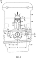
- Figs. 1 and 2 depicts an end view of a main bearing cap 105 for a variable compression ratio engine (VCRE) 100 in a low-compression ratio (LCR) configuration; while Fig. 2 depicts the same engine in a high-compression ratio (HCR) configuration.
- the VCRE 100 can comprise a rotating crankshaft 110, connecting rods 115, and pistons 120.
- the block 125 and head 130 can be bolted together in the conventional manner, i.e., using large bolts (“head bolts”) and a compressible gasket (“head gasket”).
- the main bearing caps 105 on the VCRE 100 can be moved relative to the cylinder head 130.
- the distance between the top of the piston 120 and the top of the combustion chamber 135 can be varied to increase or decrease the total combustion volume (e.g., the volume of the combustion chamber 135 in the head + the head gasket + space above the piston, etc.). This, in turn, varies the compression ratio of the VCRE 100.
- crankshaft 110 can be moved vertically relative to the head 130. As shown, this can be accomplished by pivoting the main bearing caps 105 about one end. This requires, among other things, overcoming the force of gravity (a comparatively small force), inertia, compression, and especially combustion. Controlling these forces has been a major stumbling block for prior designs with variable compression ratio.
- the movement of the head/block assembly 125, 130 should be substantially limited to movement only in the y-axis (i.e., purely vertical movement), though, as discussed below, some minimal side motion can be absorbed by the rod 115 geometry and piston rings, among other things.
- embodiments of the present invention can comprise multiple devices to control the movement of the crankshaft 110.
- the crankshaft 110 can be mounted in pivoting main bearing caps 105 using suitable bearings 107.
- the main bearings 107 can comprise, for example and not limitation, plain bearings, needle bearings, or roller bearings.
- the pivoting main bearing caps 105 can be pivotally coupled to the block 125 on a first end 105a and coupled to an actuator 140 on a second end 105b. As shown in comparing Fig. 1 to Fig. 2 , this can enable the main bearing caps 105 to be rotated about a first radius (R1), which in turn rotates the crankshaft 110 along a second radius (R2).
- R2 can be half of R1.
- R2/R1 this ratio
- other geometries could be used to increase or decrease this ratio (R2/R1) to, for example, increase compression ratio change, mechanical advantage, or positioning accuracy.
- the first end 105a bearing caps 105 can be pivotable mounted to the block 125 using a shaft 150 and pedestals 155 (i.e., similar to a shaft mounted rocker arm).
- a shaft 150 and pedestals 155 i.e., similar to a shaft mounted rocker arm.
- provisions for the shaft 150 and bearing caps 105 can be cast directly into a one-piece or multi-piece block 125.
- the first end 105a of the bearing cap 105 can simply be a machined surface mounted on a shaft 150.
- the first end 105a of the bearing caps 105 can comprise, for example and not limitation, plain bearings, roller bearings, and needle bearings.
- the bearing caps 105 can be mounted with ball and socket joints and a lock nut, similar to those used for conventional stamped rocker arms.
- the second end 105b of the caps 105 can be connected to the pivoting mechanism 140 to enable the caps 105 to be pivoted about the shaft 150.
- the second end 105b of the cap 105 can be connected to an eccentric, or cam 140, via a dog bone 145, or other suitable link.
- the cam 140 can comprise a central shaft 140a and an eccentric 140b. In this manner, when the cam 140 is rotated, the dogbone 145 can raise or lower the bearing caps 105 in unison to maintain their alignment.
- the cam 140 can be rotated by an internal or external gear 147, or other suitable means. See , Fig. 6 .
- each cap 105 could be mounted on a hydraulic lifter, for example, with all of the lifters on a common hydraulic or pneumatic circuit (e.g., using engine oil pressure or a separate hydraulic or pneumatic circuit). In this manner, hydraulic or pneumatic pressure could be used to move the caps 105 in unison. In other embodiments, the caps 105 could be moved using, for example and not limitation, servo motors, linear servos, hydraulic or pneumatic rams, shape metal alloys (SMAs), or magneto rheological actuators.
- SMAs shape metal alloys
- the actuators 140 can also include a spring to return the bearing caps 105 to a "default" position (e.g., the HCR or LCR position).
- the springs can comprise, for example and not limitation, conventional wound springs, SMAs, "mouse” type springs, or torsion bars.
- crankshaft 110 there are several problems associated with raising and lowering the crankshaft 110.
- One problem is that, if a conventional one-piece crankshaft is used, then it is difficult, if not impossible to seal the ends of the crankshaft 110 that protrude from the block.
- Conventional lips seals for example, are simply not flexible enough to seal even this small movement (on the order of 0.2", depending on the application). As a result, these types of seals would likely leak and/or fail in short order.
- a second problem is how to reliably take power off of the crankshaft 110, e.g., for the transmission on the back and the accessory drive on the front, when the crankshaft 110 is not stationary.
- embodiments of the present invention can also comprise a system and method for providing a crankshaft 110 with one or more movable components and one or more stationary output points.
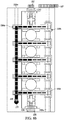
- the system 300 can comprise what is essentially a one piece crankshaft 110 that includes one or more flex joints 310.
- the main bearing journals of the crankshaft 110 can be mounted as described above, i.e., using the aforementioned pivoting bearing caps 105. This allows the portion of the crankshaft 110 containing the crankpins (i.e., the center of the crankshaft 110 where the connecting rods 115 are affixed) to be raised and lowered relative to the cylinder head 130.
- the flex joints 310 can enable the crankshaft 110 to feed power directly to the front and rear of the engine 100 along a fixed longitudinal axis, as in a conventional engine.
- crankshaft 110 extends through the block 125 in a fixed location on a shared, fixed axis L 1 , and provides power in the conventional manner (e.g., powering a hub assembly, balancer, drive pulleys, flywheel, or directly powering a transmission), without the need for gear drives, or other complex and inefficient means.
- the snout 315 of the crankshaft 110 can protrude through the block in the conventional manner and using a convention oil seal 320.
- the block 125 for a four cylinder VCRE engine 100 can be substantially similar to that of the block for a six cylinder conventional engine.
- conventional, mature manufacturing techniques can be used to provide high-quality at relatively low manufacturing costs.
- the joints 310 can substantially occupy the position formerly occupied by the piston and rod in cylinders 1 and 6 of a conventional six cylinder.
- the cylinder head 130, valve cover, and block for example, can be sized for a four cylinder engine, while the crankcase is essentially the size of a six cylinder engine.
- This space can be used efficiently, however, by, for example, placing the accessories over this area on the front of the engine 100 (where they would normally be mounted completely in front of the engine).
- the top or bottom of these overhangs can include a plate, or service port, to replace or service the flex joints 310 to minimize maintenance costs.
- the system 300 can include one or more service covers 325 and a conventional oil pan 330.
- the service covers 325 can enable the flex joints 310 to be conveniently inspected and serviced, as necessary, without removal of the engine from the vehicle.
- the oil pan 330 can include, for example, the sump for the oil pump, a drain plug, baffles, and other components as in a conventional oil pan.
- the covers 325 and oil pan 330 can be sealed in the conventional manner (e.g., using silicone or a gasket) and can be affixed to the block 125 using bolts, or other suitable means.
- the engine block can be sized essentially the same as for a four cylinder engine with the addition of "nose cones" located in the front and rear of the block to house the flex joints. This design has the added benefit of allowing easier access to the flex joints if maintenance or replacement is required.
- the system 350 can comprise a four cylinder block 355 with one or more output tailshaft housings 360.
- the engine 350 can have substantially the same size and weight as a four cylinder engine.
- the tailshaft housings 360 can be detachably coupled to the engine 350 with, for example, bolts and an appropriate seal (e.g., silicone, o-ring, gasket, etc.). In this configuration, the tailshaft housings 360 can be removed to enable the flex joints 310 to be serviced.
- the tailshaft housings can also comprise a seal 365 (e.g., a conventional lip seal) to seal the crankshaft snout 315 where it protrudes through the tailshaft housing 360.
- the tailshaft housing 360 can further comprise a bushing or bearing to support the crankshaft snout 315.
- the bushing can be, for example, a bronze bushing similar to that used in a transmission tailshaft.
- the bearing can be, for example and not limitation, a plain bearing, a roller bearing, or a taper bearing.
- the block 125 can be machined from billet or cast such that it comprises pockets 520a, 520b to enable the main bearing caps 105 to pivot within the block 125.
- the block 125 can also comprise one or more bosses 525a, 525b to house the pivot shaft 150 and actuator shaft 140a, respectively.
- the pivot shaft 150 can be inserted through the boss 525a in the front of the block 125 and through the main bearing caps 105 to enable the main bearing caps 105 to pivot thereon.
- the shaft 150 can include threads 510 and can be threadably engaged with the block 125.
- the block 125 can also include an oil passageway 515 to provided pressurized oil to the pivot shaft 150, main bearing caps 105, main bearings 107, and/or actuators 140.
- the actuator shaft 140a can be inserted through a boss 525b in the back of the block 125 and through the dogbones (or followers) 145, or other actuating means.
- the boss 525b cab also act as an oil passage to feed pressurized oil through the actuator shaft 140a, actuators 140, dogbones 145, main bearing caps 105, main bearings 107, and or the pivot shaft 150.
- one of the pivot shaft 150 and the actuator shaft 140a can act as an oil supply, while the other of the pivot shaft 150 and the actuator shaft 140a can act as an oil return.
- these joints 310 can comprise double cardan joints, as shown, and can include an input 310a, two universal joints 310b connected with a center yoke 310c, and an output 310d.
- the crankshaft 110 can act essentially as a one piece crankshaft 110 (i.e., power is transmitted directly through the shaft), while enabling the outputs 310d to remain stationary.
- conventional seals, drive systems, flywheels, and other components can remain essentially the same as in conventional engines. This eliminates the weight, complexity, and mechanical inefficiency, among other things, of multiple slave shafts, gears, or other linkages.
- the flex joints 310 can also comprise, for example and not limitation, a single universal joint, Tracta joints, Rzeppa joints, Weiss joints, tripod joints, Thompson couplings, Malpezzi joints, flex-discs (or, "guibos"), jaw couplings, and any other flexible drive joint.
- a single universal joint Tracta joints, Rzeppa joints, Weiss joints, tripod joints, Thompson couplings, Malpezzi joints, flex-discs (or, "guibos”), jaw couplings, and any other flexible drive joint.
- joints 310 Using these joints 310 enables the outputs 310d to be conventionally mounted in the block 125 in a fixed position. This enables the outputs 310d to be rotatably mounted in convention plain or roller bearings, for example, with pressurized oiling. This fixed mounting also enables the outputs 310d to be sealed using conventional lip or rope seals (e.g., using a conventional "front and rear main seal"), or other suitable means.
- the joints 310 can be splash oiled with oil from the sump of the engine.
- one or more pressurized oil jets, such as those used for piston cooling can be provided to lubricate the joints 310.
- the output shaft can power hub assemblies located in fixed locations on the block. This can eliminate the need for pressurized oil supply to the hub bearings. This embodiment eliminates the loads of combustion and compression that are normally exerted on the main bearings 107, thus allowing for the use of conventional roller bearings, or similar, commonly found in hub assemblies.
- the joints 310 can be appropriately sized to transmit the torque of the engine to the outputs 310d. It should be noted, however, the conventional u-joints in a rear wheel drive vehicle reliably transmit the torque from the engine to the differential after it has been multiplied by the transmission (e.g., generally in excess of 3X in first gear). As a result, the joints 310 can be relatively small and light when compared to conventional driveshaft u-joints or CV joints.
- the service life of the joints 310 should meet or exceed the life of conventional driveshaft u-joints, which is on the order of 100,000 miles or more.
- the block 125 can comprise seven main bearings caps 105, as in a conventional six cylinder, with the number 1 and 7 bearings 105 rotatably supporting the output 310d portion of the crankshaft 110.
- the block 125 can comprise five main bearings caps 105 to support the main bearings 107 of the crankshaft 110, while the output 310d portion(s) of the crankshaft 110 can be supported in separate bearings 530.
- main bearings caps 105 can be used as in a conventional V8 engine (i.e., one bearing cap 105 for each pair of crankshaft 110 throws) with the outputs 310d supported in separate bearings 530.
- the main bearings 107 and the output bearings 317 can comprise many types of bearings known in the art including, but not limited to, plain bearings, roller bearings, and needle bearings.
- the caps 105 can further comprise one or more alignment bars 605.
- the alignment bar(s) 605 can be located, for example, above the actuators 140 and bolted (or otherwise detachably coupled to the caps 105) to ensure that that caps 105 move in unison.
- the system can comprise a plurality of alignment bars 605 located, for example, at the first end 105a, the middle, and the second end 105b of the caps to maintain their alignment.
- the alignment bar(s) 605 can comprise, for example, aluminum, steel, cast iron, composites, or combinations thereof. Maintaining the alignment of the caps 105 can help reduce vibration and bearing wear, among other things.
- the alignment of the caps 105 can be maintained using an external stud girdle 705, such as those found on high performance engines.
- the stud girdle 705 can comprise a cast or machined brace with a relatively high tensile strength and high rigidity.
- the stud girdle 705 can comprise, for example, aluminum, steel, cast iron, composites, or combinations thereof.
- the girdle 705 can mount onto extended studs or be bolted to the caps 105, and can increase the rigidity and stability of the caps 105, creating a substantially monolithic unit.
- the girdle 705 can help prevent alignment issues and side loading, among other things, increasing bearing life and reducing vibration.
- the shaft 150 and or pedestals 155 can be used to provide pressurized oil to the bearing caps 105 and/or bearings 107.
- pressurized oil can be provided via oil passages in the block 125 and directly through the pedestals 155, the shaft 150, and bearing caps 105.
- pressurized oil can be provided through a hollow shaft 150 from one end of the engine and fed to the bearing caps 105 through oiling holes and passages (similar to those found in conventional main bearings). In this manner, pressurized oil can be provided through passages in the main caps 105 to the main bearings 107 and/or the second end 105b of the caps 105 and pivoting mechanism 140.
- pressurized oil can be provided through a shaft 140a, or other means, associated with the second end 105b.
- one of the pivot shaft 150 and the actuator shaft 140a can act as an oil supply, while the other of the pivot shaft 150 and the actuator shaft 140a can act as an oil return.
- the system 100 architecture enables a variable compression ratio engine 900 that can be sealed in the conventional manner and that interfaces with conventional components in the conventional manner.
- the balancer 905 and front pulleys 910 are stationary to enable convenient power take-off for the front accessories (e.g., an alternator 915) and to drive the timing belt 920, as necessary.
- the crankshaft 110 can be easily connected to a conventional transmission 925 in the conventional manner.
- Table 1 contains dimensions suitable for a wide variety of engine configurations. The exact dimensions used below are common to the ubiquitous 350 c.i. (5.7L) "small block” Chevrolet engine produced by General Motors. LCR MCR HCR Bore 4.00” 4.00” 4.00” Stroke 3.500” 3.500” 3.500" Head Gasket Bore Diameter 4.030" 4.030" 4.030" Compressed Head Gasket Height 0.021" 0.021" 0.021" Cylinder Head Combustion Chamber Volume 80cc 80cc 80c Piston Dome 19.5cc 19.5cc Piston height (below Deck Height) -0.2" -0.1" 0.0" Total Combustion Chamber Volume 106.07cc 85.48cc 64.89cc Compression Ratio 7.79 9.43 12.11
- a middle compression ratio (MCR) of 9.43:1 compression ratio is a good mid-load/mid-quality fuel compression ratio. This is in the range of many modern engines' compression ratios, which tend to fall between 9.0:1 and 10.5:1. This can enable the engine to work fairly efficiently in a wide variety of situations or with a fairly wide range of fuel qualities. With proper cooling (e.g., after- or intercooling), this MCR could also be used with modest amounts of boost (e.g., 5-6 PSI) from a turbo- or supercharger to provide increased power and efficiency.
- boost e.g., 5-6 PSI
- the high-compression position is approaching the limits of compression ratio for standard "pump" gasoline in a conventional engine.
- Higher compression ratios are, at present, generally reserved for exotic sports cars and motorcycles.
- the "standard" compression ratio limit of around 12:1 can be raised with careful combustion chamber design and special controls such as, for example and not limitation, direct injection and knock sensors, which enable control of spark and fuel delivery to reduce detonation.
- These features can require expensive electronics, pumps, and fuel injectors, however, to achieve this performance.
- Embodiments of the present invention can enable the used of very high compression ratios, not due to expensive components and controls, but when the conditions under which the engine is operating are appropriate (e.g., high-quality fuel, low ambient temperatures, etc.). This can enable a relatively conventional engine design to yield the increased performance and efficiency of very high compression ratios without detonation or other deleterious side effects.
- the primary benefit of utilizing a high compression ratio is the improved efficiency and fuel economy achieved when the engine is under light loads, such as idling at traffic signals and/or cruising at highway speeds. This ability to increase compression ratio under light loads significantly increases fuel economy (30% or more).
- crank height can simply be controlled as an additional engine parameter - like ignition timing and fuel delivery - to maximize performance and minimize detonation, emissions, fuel consumption, and other harmful effects.
- the system can substantially continuously change crank height based on feedback from, for example, oxygen sensors, throttle position sensors, knock sensors, and intake air and engine temperature sensors to maximize torque, horsepower, and fuel economy, while minimizing heat build-up, detonation, and harmful emissions (e.g., oxides of nitrogen).
- the system 100 can also be used for maximizing efficiency on a particular fuel or in conjunction with a particular power adder. If the engine is designed to burn E85 (85% ethanol/15% gasoline), for example, the compression ratio range can be shifted (or expanded) to provide even higher compression ratios (up to approximately 14.5:1). This can be helpful, for example, because E85 provides less energy than gasoline and thus, provides approximately 20-30% poorer fuel mileage. Some of this loss could be recovered, however, if E85 was simply burned more efficiently (i.e., at a higher compression ratio). E85 also burns more cleanly and at a lower temperature than gasoline, which can reduce emissions and increase engine life. Ethanol can also be produced from renewable sources and in an eco-friendly manner.
- the system 100 can also be used in conjunction with power adders to maximize efficiency.
- the system 100 can be used in conjunction with a turbocharger, for example, to decrease spool-up time and "turbo-lag.” This can be accomplished, for example, by maintaining a relatively high compression ratio when the turbo charger is below a predetermined amount of boost to reduce turbo lag. As the turbo spools-up, however, the compression ratio can be mechanically lowered with the crankshaft 110 to prevent overboosting, which can cause detonation, blown head gaskets, and other mechanical issues.
- the movement of the crankshaft 110 would ideally be completely vertical. And while this can be achieved using a combination of mechanisms discussed above, the design can be somewhat simpler with a pivoting cap 105. As discussed in Example 1, however, the distances through which the crank must be moved are relatively small. In addition, as shown in Fig 10 , the geometries are such that the side movement of the crankshaft 110 is extremely small.
- crankshaft 0.2 provides an excellent range of compression ratios.
- the main bearing caps 105 can be substantially horizontal in the MCR position. In this manner, the main bearing caps 105 can be pivoted down 0.1" to the LCR position and up 0.1" to the HCR position. This would reduce the horizontal movement of the crankshaft 110 to approximately .0005", further reducing, for example, bearing wear and harmonics.
- a control system 1000 can be used to monitor and control the position of the crankshaft 110 using feedback from various engine sensors and one of the actuators 140 discussed above, for example.
- the control system 1000 can use normal inputs from one or more sensors such as, for example and not limitation, manifold absolute pressure (MAP) sensors 1005 (or Mass airflow (MAF) sensors), throttle position sensors (TPS) 1010, air intake temperature (AIT) sensors 1015, oxygen (O2) sensors 1020, knock sensors 1025, and coolant temperature sensors (CTS) 1030, among other sensors, to continuously move the crankshaft 110 to maintain optimum efficiency.
- MAP manifold absolute pressure
- MAF Mass airflow
- TPS throttle position sensors
- AIT air intake temperature
- O2 oxygen
- CTS coolant temperature sensors
- the actuator 140 can be a stepper motor, for example, enabling the control system 1000 to monitor the position of the crankshaft.
- the system 1000 can include a position sensor (e.g., an optical or resistance sensor) to monitor the position of the crankshaft 110.
- the system 1000 can use a controller 1035, for example, which can comprise a computer or microprocessor to constantly monitor and change engine parameters such as, for example and not limitation, ignition timing 1040, fuel injector pulse width 1045 (i.e., fuel mixture), and crankshaft 110 position (using one of the actuators 140 described above) to maximize efficiency, maintain engine temperature (i.e., prevent overheating), and to reduce knock.
- the controller may use one or more servos, or stepper motors, to reposition the crankshaft 110 in real time.
Landscapes
- Engineering & Computer Science (AREA)
- General Engineering & Computer Science (AREA)
- Mechanical Engineering (AREA)
- Chemical & Material Sciences (AREA)
- Combustion & Propulsion (AREA)
- Ocean & Marine Engineering (AREA)
- Output Control And Ontrol Of Special Type Engine (AREA)
- Shafts, Cranks, Connecting Bars, And Related Bearings (AREA)
Claims (13)
- Kurbelwellensystem zur Bereitstellung eines variablen Kompressionsverhältnisses in einer Brennkraftmaschine, umfassend einen Block (125) und einen Zylinderkopf (130), wobei das System folgendes umfasst:eine Kurbelwelle (110), umfassend:einen ersten, festen Ausgang, der ein erstes Ende und ein zweites Ende umfasst;einen zentralen Teil mit einem ersten Ende und mit einem zweiten Ende, umfassend einen oder mehrere Kurbelwellenzapfen und zwei oder mehr Hauptlagerzapfen;einen zweiten, festen Ausgang, der ein erstes Ende und ein zweites Ende umfasst;ein erstes elastisches Gelenk (310), welches das zweite Ende des ersten Ausgangs mit dem ersten Ende des zentralen Teils koppelt; undein zweites elastisches Gelenk (310), welches das erste Ende des zweiten Ausgangs mit dem zweiten Ende des zentralen Teils koppelt;eine Mehrzahl von Hauptlagerdeckeln (105), wobei jeder Hauptlagerdeckel ein erstes Ende und ein zweites Ende aufweist, wobei jedes erste Ende drehbar mit dem Block gekoppelt ist, um die Hauptlagerzapfen drehbar zu lagern;eine Mehrzahl von Aktoren (140), die jeweils proximal zu den zweiten Enden der Mehrzahl von Hauptlagerdeckeln angeordnet sind, um den zentralen Teil der Kurbelwelle zwischen einer ersten Position eines niedrigen Kompressionsverhältnisses (LCR) und einer zweiten Position eines hohen Kompressionsverhältnisses (HCR) zu bewegen;wobei der erste und der zweite Ausgang im Wesentlichen koaxial sind mit den zwei oder mehr Hauptlagerzapfen des zentralen Teils an einer Position eines mittleren Kompressionsverhältnisses (MCR);und wobei sich der erste und der zweite Ausgang um eine feste Längsachse drehen.
- System nach Anspruch 1, wobei die Mehrzahl von Aktoren Hydraulikstößel umfasst.
- System nach Anspruch 1, wobei die Mehrzahl von Aktoren Hydraulikstößel folgendes umfasst:eine Mehrzahl von Stößeln, die jeweils ein erstes Ende und ein zweites Ende aufweisen, wobei das erste Ende drehbar mit dem zweiten Ende der Mehrzahl von Hauptdeckeln verbunden ist; undeine Nockenwelle, die eine Welle und einen oder mehrere Nocken umfasst, die drehbar mit der Mehrzahl von Stößeln eingreifen, um die Kurbelwelle zwischen der ersten Position eines niedrigen Kompressionsverhältnisses (LCR) und der zweiten Position eines hohen Kompressionsverhältnisses (HCR) zu bewegen.
- System nach Anspruch 1, wobei die Mehrzahl von Aktoren Servomotoren umfassen.
- System nach Anspruch 1, ferner umfassend:
eine Hauptlagerdeckel-Trägerwelle zur drehbaren Kopplung des ersten Endes der Mehrzahl von Hauptlagerdeckeln mit dem Block. - System nach Anspruch 1, ferner umfassend eine oder mehrere Ausrichtungswellen (605), die lösbar mit einem Teil der Mehrzahl von Hauptlagerdeckeln gekoppelt sind, um die Ausrichtung der Mehrzahl von Hauptlagerdeckeln aufrechtzuerhalten.
- Kurzblocksystem zur Bereitstellung eines Motors mit variablem Kompressionsverhältnis, umfassend das Kurbelwellensystem aus Anspruch 1, wobei die Kurbelwelle ein erstes Ende und ein zweites Ende umfasst, wobei das Kurzblocksystem ferner folgendes umfasst:einen Hauptmotorblock mit einem ersten, vorderen Ende und einem zweiten, hinteren Ende;wobei die Längsachse des ersten und des zweiten Ausgangs um nicht mehr als 1,27 cm von der Längsachse der Kurbelwelle an der LCR- und HCR-Position versetzt ist.
- System nach Anspruch 7, wobei der erste Ausgang ferner folgendes umfasst:eine erste Kurbelwellennase (315), die durch eine erste Öffnung vordem Hauptmotorblock vorsteht; undeine erste Dichtlippe (365) zur Abdichtung eines Zwischenraums zwischen der ersten Kurbelwellennase und der ersten Öffnung.
- System nach Anspruch 8, wobei der zweite Ausgang ferner folgendes umfasst:eine zweite Kurbelwellennase (315), die durch eine zweite Öffnung auf der Rückseite des Hauptmotorblocks vorsteht; undeine zweite Dichtlippe (365) zur Abdichtung eines Zwischenraums zwischen der zweiten Kurbelwellennase und der zweiten Öffnung.
- System nach Anspruch 9, wobei die erste Kurbelwellennase lösbar mit einer oder mehreren Zusatzantriebsscheiben (910) und einem Ausgleichsregler (905) gekoppelt ist; und
wobei die zweite Kurbelwellennase lösbar mit einem Schwungrad gekoppelt ist. - System nach Anspruch 7, wobei der Block ferner eine Mehrzahl von Trägersockeln zum Tragen des ersten Endes der Mehrzahl von Hauptlagerdeckeln umfasst; und
eine Hauptlagerdeckel-Trägerwelle zur drehbaren Kopplung des ersten Endes der Mehrzahl von Hauptlagerdeckeln mit der Mehrzahl von Trägersockeln. - System nach Anspruch 7, ferner umfassend einen Hauptlagergürtel (705), der lösbar mit der Mehrzahl von Hauptlagerdeckeln gekoppelt ist, um die Ausrichtung der Hauptlagerdeckel aufrechtzuerhalten.
- System nach Anspruch 7, wobei jeder Deckel der Mehrzahl von Hauptlagerdeckeln ferner einen oder mehrere Ölkanäle umfasst, um unter Druck stehendes Öl an einen oder mehrere der Hauptlagerzapfen und die Mehrzahl von Aktoren bereitzustellen.
Applications Claiming Priority (3)
| Application Number | Priority Date | Filing Date | Title |
|---|---|---|---|
| US201361819032P | 2013-05-03 | 2013-05-03 | |
| US201361822802P | 2013-05-13 | 2013-05-13 | |
| PCT/US2014/036683 WO2014179758A1 (en) | 2013-05-03 | 2014-05-02 | Variable compression ratio engine |
Publications (3)
| Publication Number | Publication Date |
|---|---|
| EP2992200A1 EP2992200A1 (de) | 2016-03-09 |
| EP2992200A4 EP2992200A4 (de) | 2016-04-20 |
| EP2992200B1 true EP2992200B1 (de) | 2019-07-03 |
Family
ID=51840754
Family Applications (1)
| Application Number | Title | Priority Date | Filing Date |
|---|---|---|---|
| EP14791396.6A Active EP2992200B1 (de) | 2013-05-03 | 2014-05-02 | Motor mit variablem verdichtungsverhältnis |
Country Status (7)
| Country | Link |
|---|---|
| US (2) | US9200564B2 (de) |
| EP (1) | EP2992200B1 (de) |
| JP (1) | JP6084334B2 (de) |
| KR (2) | KR101748555B1 (de) |
| CA (2) | CA2910872C (de) |
| MX (2) | MX373449B (de) |
| WO (1) | WO2014179758A1 (de) |
Cited By (2)
| Publication number | Priority date | Publication date | Assignee | Title |
|---|---|---|---|---|
| US20220112848A1 (en) * | 2020-10-12 | 2022-04-14 | Schaeffler Technologies AG & Co., KG | Actuation assembly for phaser system |
| US20220252015A1 (en) * | 2021-02-11 | 2022-08-11 | Schaeffler Technologies AG & Co. KG | Cranktrain phase adjuster for variable compression ratio |
Families Citing this family (3)
| Publication number | Priority date | Publication date | Assignee | Title |
|---|---|---|---|---|
| US9765865B2 (en) * | 2013-02-07 | 2017-09-19 | Medinol Ltd. | Variable linear motor |
| EP2992200B1 (de) | 2013-05-03 | 2019-07-03 | Blackstock, Scott | Motor mit variablem verdichtungsverhältnis |
| US11428173B2 (en) * | 2020-10-06 | 2022-08-30 | Schaeffler Technologies AG & Co. KG | Cranktrain phase adjuster for variable compression ratio |
Family Cites Families (30)
| Publication number | Priority date | Publication date | Assignee | Title |
|---|---|---|---|---|
| GB353986A (en) * | 1930-05-27 | 1931-08-06 | Henri Kundig | Improvements in a variable and regulatable compression chamber for internal combustion or other engines |
| US2987896A (en) * | 1959-03-30 | 1961-06-13 | Ford Motor Co | Double universal joint |
| DE2920074C2 (de) * | 1979-05-18 | 1985-03-14 | Fa. Carl Freudenberg, 6940 Weinheim | Laschenkupplung |
| JPS58220926A (ja) * | 1982-06-15 | 1983-12-22 | Ikuo Kato | 可変圧縮比エンジン |
| US4538557A (en) * | 1983-03-24 | 1985-09-03 | Kleiner Rudolph R | Internal combustion engine |
| DE69108572T2 (de) * | 1990-01-17 | 1995-08-17 | Mitsubishi Motors Corp | Vorrichtung zum Ändern des Kompressionverhältnisses für Brennkraftmaschine. |
| FR2688544B1 (fr) * | 1992-03-13 | 1995-08-18 | Matesic Alex | Moteur a combustion interne a hautes performances avec taux de compression et masse tournante du volant moteur ajustables en marche. |
| US5415588A (en) | 1993-06-14 | 1995-05-16 | Wier; Francis L. | Wide angle universal joint |
| JPH0953528A (ja) * | 1995-08-10 | 1997-02-25 | Yamaha Motor Co Ltd | 吸気装置を備える多気筒エンジン |
| GB9719536D0 (en) * | 1997-09-12 | 1997-11-19 | Broadsuper Ltd | Internal combustion engines |
| DE19753439A1 (de) * | 1997-12-02 | 1999-06-17 | Mannesmann Sachs Ag | Drehmomentwandler |
| NL1016492C2 (nl) | 1999-11-05 | 2001-05-08 | Walterscheid Gmbh Gkn | Bescherminrichting voor een aandrijfordening met een dubbele kruiskoppeling. |
| JP4038959B2 (ja) * | 2000-05-09 | 2008-01-30 | 日産自動車株式会社 | 内燃機関の可変圧縮比機構 |
| US6904885B2 (en) * | 2001-08-24 | 2005-06-14 | Lance Ian Osband | Osband super inductionexhaustion valveshaft' engine system, V-Type, flat-type, single-type, multi-cylinder four-cycle engine(s) |
| US6938589B2 (en) | 2002-11-07 | 2005-09-06 | Powervantage Engines, Inc. | Variable displacement engine |
| SE526640C2 (sv) * | 2004-02-24 | 2005-10-18 | Saab Automobile | Kolvmotor för ett motorfordon innefattande ett kopplingsarrangemang för överföring av vridmoment från en vevaxelände till en i cylinderblocket lagrad vevaxelfläns |
| DE102005050813A1 (de) * | 2005-10-24 | 2007-04-26 | Joachim Schmauder | Veränderung des Verdichtungsverhältnisses eines Hubkolbentriebwerkes durch verstellbare Halterung der Kurbelwellenlagerung |
| EP1965051B1 (de) * | 2006-09-12 | 2016-01-06 | Honda Motor Co., Ltd. | Motoranordnung mit variablen hubeigenschaften |
| JP4462283B2 (ja) * | 2007-03-14 | 2010-05-12 | 日産自動車株式会社 | エンジン負荷推定装置及びエンジン負荷推定方法 |
| US7823563B2 (en) * | 2008-05-08 | 2010-11-02 | Ford Global Technologies, Llc | Cylinder-by-cylinder balancing of combustion timing in HCCI engines |
| KR100969385B1 (ko) * | 2008-07-07 | 2010-07-09 | 현대자동차주식회사 | 가변 압축비 장치 |
| CN101333970A (zh) * | 2008-07-29 | 2008-12-31 | 奇瑞汽车股份有限公司 | 一种可变压缩比发动机 |
| JP5146250B2 (ja) * | 2008-10-20 | 2013-02-20 | 日産自動車株式会社 | 複リンク式エンジンの振動低減構造 |
| KR101020826B1 (ko) * | 2008-12-02 | 2011-03-09 | 현대자동차주식회사 | 가변 압축비 장치 |
| DE102009038180A1 (de) * | 2009-08-20 | 2011-03-24 | GM Global Technology Operations, Inc., Detroit | Fahrzeugmotor mit einem Kurbeltrieb für eine variable Verdichtung |
| US8267055B2 (en) * | 2009-09-03 | 2012-09-18 | Manousos Pattakos | Variable compression ratio engine |
| JP5177303B2 (ja) * | 2009-12-28 | 2013-04-03 | トヨタ自動車株式会社 | 火花点火式内燃機関 |
| JP5625481B2 (ja) * | 2010-05-21 | 2014-11-19 | 日産自動車株式会社 | 複リンク式ピストン−クランク機構を備えた内燃機関 |
| CN102877960A (zh) * | 2012-10-17 | 2013-01-16 | 赵立军 | 可变压缩比发动机 |
| EP2992200B1 (de) * | 2013-05-03 | 2019-07-03 | Blackstock, Scott | Motor mit variablem verdichtungsverhältnis |
-
2014
- 2014-05-02 EP EP14791396.6A patent/EP2992200B1/de active Active
- 2014-05-02 JP JP2016512082A patent/JP6084334B2/ja active Active
- 2014-05-02 US US14/268,905 patent/US9200564B2/en active Active
- 2014-05-02 KR KR1020177003126A patent/KR101748555B1/ko active Active
- 2014-05-02 MX MX2015015258A patent/MX373449B/es active IP Right Grant
- 2014-05-02 CA CA2910872A patent/CA2910872C/en active Active
- 2014-05-02 WO PCT/US2014/036683 patent/WO2014179758A1/en not_active Ceased
- 2014-05-02 KR KR1020157034054A patent/KR20150143861A/ko not_active Ceased
- 2014-05-02 CA CA2965182A patent/CA2965182C/en active Active
-
2015
- 2015-10-29 US US14/926,036 patent/US9822701B2/en active Active
- 2015-10-30 MX MX2020004111A patent/MX2020004111A/es unknown
Non-Patent Citations (1)
| Title |
|---|
| None * |
Cited By (4)
| Publication number | Priority date | Publication date | Assignee | Title |
|---|---|---|---|---|
| US20220112848A1 (en) * | 2020-10-12 | 2022-04-14 | Schaeffler Technologies AG & Co., KG | Actuation assembly for phaser system |
| US11619182B2 (en) * | 2020-10-12 | 2023-04-04 | Schaeffler Technologies AG & Co. KG | Actuation assembly for phaser system |
| US20220252015A1 (en) * | 2021-02-11 | 2022-08-11 | Schaeffler Technologies AG & Co. KG | Cranktrain phase adjuster for variable compression ratio |
| US11519342B2 (en) * | 2021-02-11 | 2022-12-06 | Schaeffler Technologies AG & Co. KG | Cranktrain phase adjuster for variable compression ratio |
Also Published As
| Publication number | Publication date |
|---|---|
| JP6084334B2 (ja) | 2017-02-22 |
| EP2992200A4 (de) | 2016-04-20 |
| CA2965182C (en) | 2018-12-18 |
| JP2016516947A (ja) | 2016-06-09 |
| US9200564B2 (en) | 2015-12-01 |
| EP2992200A1 (de) | 2016-03-09 |
| CA2910872C (en) | 2017-10-17 |
| US9822701B2 (en) | 2017-11-21 |
| US20160047301A1 (en) | 2016-02-18 |
| MX373449B (es) | 2020-04-23 |
| CA2965182A1 (en) | 2014-11-06 |
| CA2910872A1 (en) | 2014-11-06 |
| MX2020004111A (es) | 2020-07-24 |
| US20140326219A1 (en) | 2014-11-06 |
| KR20170018098A (ko) | 2017-02-15 |
| WO2014179758A1 (en) | 2014-11-06 |
| MX2015015258A (es) | 2016-11-08 |
| KR20150143861A (ko) | 2015-12-23 |
| KR101748555B1 (ko) | 2017-06-19 |
Similar Documents
| Publication | Publication Date | Title |
|---|---|---|
| US9822701B2 (en) | Variable compression ratio engine | |
| US5025757A (en) | Reciprocating piston engine with a varying compression ratio | |
| EP2932067B1 (de) | Motor mit variablem verdichtungsverhältnis | |
| EP1216348B1 (de) | Brennkraftmaschine mit variablem Verdichtungsverhältnis und einstellbar Ventilsteuerung | |
| Rajput | A text book of automobile engineering | |
| US20040255879A1 (en) | Harmonic sliding slotted link mechanism for piston engines | |
| JPH0726981A (ja) | 可変圧縮比内燃機関 | |
| US10428863B2 (en) | Variable compression ratio engine | |
| KR20090027603A (ko) | 풀링 로드 엔진 | |
| CA2395915C (en) | Internal combustion engines | |
| CA2598106C (en) | Diesel aircraft engine | |
| CA2225218A1 (en) | A vertical internal combustion engine | |
| CN2580121Y (zh) | 一种微型车后轮驱动用汽油发动机 | |
| US4516541A (en) | Internal combustion engine with supercharger | |
| JPH0733776B2 (ja) | ロータリー内燃機関 | |
| CN1280530C (zh) | 双缸同时作功单曲轴对顶活塞内燃机 | |
| CN2900811Y (zh) | 双曲轴连杆机构发动机 | |
| WO2007081222A1 (en) | Variable compression system for internal combustion engines | |
| WO2003095813A1 (en) | Axially aligned opposed piston engine | |
| Diggs | A Potential Solution for High-Efficiency Aircraft Powerplants-the Scotch Yoke X-Engine Aero-Diesel | |
| WO2025230437A1 (ru) | Двухтактный оппозитный двигатель внутреннего сгорания | |
| CN112761786A (zh) | V型双作功汽油机 | |
| JPH09256866A (ja) | 対面ピストンディーゼル内燃機関 |
Legal Events
| Date | Code | Title | Description |
|---|---|---|---|
| PUAI | Public reference made under article 153(3) epc to a published international application that has entered the european phase |
Free format text: ORIGINAL CODE: 0009012 |
|
| 17P | Request for examination filed |
Effective date: 20151119 |
|
| AK | Designated contracting states |
Kind code of ref document: A1 Designated state(s): AL AT BE BG CH CY CZ DE DK EE ES FI FR GB GR HR HU IE IS IT LI LT LU LV MC MK MT NL NO PL PT RO RS SE SI SK SM TR |
|
| AX | Request for extension of the european patent |
Extension state: BA ME |
|
| A4 | Supplementary search report drawn up and despatched |
Effective date: 20160322 |
|
| RIC1 | Information provided on ipc code assigned before grant |
Ipc: F02D 15/02 20060101AFI20160316BHEP |
|
| DAX | Request for extension of the european patent (deleted) | ||
| STAA | Information on the status of an ep patent application or granted ep patent |
Free format text: STATUS: EXAMINATION IS IN PROGRESS |
|
| 17Q | First examination report despatched |
Effective date: 20170221 |
|
| GRAP | Despatch of communication of intention to grant a patent |
Free format text: ORIGINAL CODE: EPIDOSNIGR1 |
|
| STAA | Information on the status of an ep patent application or granted ep patent |
Free format text: STATUS: GRANT OF PATENT IS INTENDED |
|
| INTG | Intention to grant announced |
Effective date: 20190129 |
|
| GRAS | Grant fee paid |
Free format text: ORIGINAL CODE: EPIDOSNIGR3 |
|
| GRAA | (expected) grant |
Free format text: ORIGINAL CODE: 0009210 |
|
| STAA | Information on the status of an ep patent application or granted ep patent |
Free format text: STATUS: THE PATENT HAS BEEN GRANTED |
|
| AK | Designated contracting states |
Kind code of ref document: B1 Designated state(s): AL AT BE BG CH CY CZ DE DK EE ES FI FR GB GR HR HU IE IS IT LI LT LU LV MC MK MT NL NO PL PT RO RS SE SI SK SM TR |
|
| REG | Reference to a national code |
Ref country code: GB Ref legal event code: FG4D |
|
| REG | Reference to a national code |
Ref country code: CH Ref legal event code: EP Ref country code: AT Ref legal event code: REF Ref document number: 1151299 Country of ref document: AT Kind code of ref document: T Effective date: 20190715 |
|
| REG | Reference to a national code |
Ref country code: IE Ref legal event code: FG4D |
|
| REG | Reference to a national code |
Ref country code: DE Ref legal event code: R096 Ref document number: 602014049536 Country of ref document: DE |
|
| REG | Reference to a national code |
Ref country code: NL Ref legal event code: MP Effective date: 20190703 |
|
| REG | Reference to a national code |
Ref country code: LT Ref legal event code: MG4D |
|
| REG | Reference to a national code |
Ref country code: AT Ref legal event code: MK05 Ref document number: 1151299 Country of ref document: AT Kind code of ref document: T Effective date: 20190703 |
|
| PG25 | Lapsed in a contracting state [announced via postgrant information from national office to epo] |
Ref country code: AT Free format text: LAPSE BECAUSE OF FAILURE TO SUBMIT A TRANSLATION OF THE DESCRIPTION OR TO PAY THE FEE WITHIN THE PRESCRIBED TIME-LIMIT Effective date: 20190703 Ref country code: NL Free format text: LAPSE BECAUSE OF FAILURE TO SUBMIT A TRANSLATION OF THE DESCRIPTION OR TO PAY THE FEE WITHIN THE PRESCRIBED TIME-LIMIT Effective date: 20190703 Ref country code: BG Free format text: LAPSE BECAUSE OF FAILURE TO SUBMIT A TRANSLATION OF THE DESCRIPTION OR TO PAY THE FEE WITHIN THE PRESCRIBED TIME-LIMIT Effective date: 20191003 Ref country code: HR Free format text: LAPSE BECAUSE OF FAILURE TO SUBMIT A TRANSLATION OF THE DESCRIPTION OR TO PAY THE FEE WITHIN THE PRESCRIBED TIME-LIMIT Effective date: 20190703 Ref country code: NO Free format text: LAPSE BECAUSE OF FAILURE TO SUBMIT A TRANSLATION OF THE DESCRIPTION OR TO PAY THE FEE WITHIN THE PRESCRIBED TIME-LIMIT Effective date: 20191003 Ref country code: LT Free format text: LAPSE BECAUSE OF FAILURE TO SUBMIT A TRANSLATION OF THE DESCRIPTION OR TO PAY THE FEE WITHIN THE PRESCRIBED TIME-LIMIT Effective date: 20190703 Ref country code: FI Free format text: LAPSE BECAUSE OF FAILURE TO SUBMIT A TRANSLATION OF THE DESCRIPTION OR TO PAY THE FEE WITHIN THE PRESCRIBED TIME-LIMIT Effective date: 20190703 Ref country code: SE Free format text: LAPSE BECAUSE OF FAILURE TO SUBMIT A TRANSLATION OF THE DESCRIPTION OR TO PAY THE FEE WITHIN THE PRESCRIBED TIME-LIMIT Effective date: 20190703 Ref country code: CZ Free format text: LAPSE BECAUSE OF FAILURE TO SUBMIT A TRANSLATION OF THE DESCRIPTION OR TO PAY THE FEE WITHIN THE PRESCRIBED TIME-LIMIT Effective date: 20190703 Ref country code: PT Free format text: LAPSE BECAUSE OF FAILURE TO SUBMIT A TRANSLATION OF THE DESCRIPTION OR TO PAY THE FEE WITHIN THE PRESCRIBED TIME-LIMIT Effective date: 20191104 |
|
| PG25 | Lapsed in a contracting state [announced via postgrant information from national office to epo] |
Ref country code: LV Free format text: LAPSE BECAUSE OF FAILURE TO SUBMIT A TRANSLATION OF THE DESCRIPTION OR TO PAY THE FEE WITHIN THE PRESCRIBED TIME-LIMIT Effective date: 20190703 Ref country code: GR Free format text: LAPSE BECAUSE OF FAILURE TO SUBMIT A TRANSLATION OF THE DESCRIPTION OR TO PAY THE FEE WITHIN THE PRESCRIBED TIME-LIMIT Effective date: 20191004 Ref country code: RS Free format text: LAPSE BECAUSE OF FAILURE TO SUBMIT A TRANSLATION OF THE DESCRIPTION OR TO PAY THE FEE WITHIN THE PRESCRIBED TIME-LIMIT Effective date: 20190703 Ref country code: ES Free format text: LAPSE BECAUSE OF FAILURE TO SUBMIT A TRANSLATION OF THE DESCRIPTION OR TO PAY THE FEE WITHIN THE PRESCRIBED TIME-LIMIT Effective date: 20190703 Ref country code: AL Free format text: LAPSE BECAUSE OF FAILURE TO SUBMIT A TRANSLATION OF THE DESCRIPTION OR TO PAY THE FEE WITHIN THE PRESCRIBED TIME-LIMIT Effective date: 20190703 Ref country code: IS Free format text: LAPSE BECAUSE OF FAILURE TO SUBMIT A TRANSLATION OF THE DESCRIPTION OR TO PAY THE FEE WITHIN THE PRESCRIBED TIME-LIMIT Effective date: 20191103 |
|
| PG25 | Lapsed in a contracting state [announced via postgrant information from national office to epo] |
Ref country code: TR Free format text: LAPSE BECAUSE OF FAILURE TO SUBMIT A TRANSLATION OF THE DESCRIPTION OR TO PAY THE FEE WITHIN THE PRESCRIBED TIME-LIMIT Effective date: 20190703 |
|
| PG25 | Lapsed in a contracting state [announced via postgrant information from national office to epo] |
Ref country code: PL Free format text: LAPSE BECAUSE OF FAILURE TO SUBMIT A TRANSLATION OF THE DESCRIPTION OR TO PAY THE FEE WITHIN THE PRESCRIBED TIME-LIMIT Effective date: 20190703 Ref country code: IT Free format text: LAPSE BECAUSE OF FAILURE TO SUBMIT A TRANSLATION OF THE DESCRIPTION OR TO PAY THE FEE WITHIN THE PRESCRIBED TIME-LIMIT Effective date: 20190703 Ref country code: RO Free format text: LAPSE BECAUSE OF FAILURE TO SUBMIT A TRANSLATION OF THE DESCRIPTION OR TO PAY THE FEE WITHIN THE PRESCRIBED TIME-LIMIT Effective date: 20190703 Ref country code: EE Free format text: LAPSE BECAUSE OF FAILURE TO SUBMIT A TRANSLATION OF THE DESCRIPTION OR TO PAY THE FEE WITHIN THE PRESCRIBED TIME-LIMIT Effective date: 20190703 Ref country code: DK Free format text: LAPSE BECAUSE OF FAILURE TO SUBMIT A TRANSLATION OF THE DESCRIPTION OR TO PAY THE FEE WITHIN THE PRESCRIBED TIME-LIMIT Effective date: 20190703 |
|
| PG25 | Lapsed in a contracting state [announced via postgrant information from national office to epo] |
Ref country code: IS Free format text: LAPSE BECAUSE OF FAILURE TO SUBMIT A TRANSLATION OF THE DESCRIPTION OR TO PAY THE FEE WITHIN THE PRESCRIBED TIME-LIMIT Effective date: 20200224 Ref country code: SM Free format text: LAPSE BECAUSE OF FAILURE TO SUBMIT A TRANSLATION OF THE DESCRIPTION OR TO PAY THE FEE WITHIN THE PRESCRIBED TIME-LIMIT Effective date: 20190703 Ref country code: SK Free format text: LAPSE BECAUSE OF FAILURE TO SUBMIT A TRANSLATION OF THE DESCRIPTION OR TO PAY THE FEE WITHIN THE PRESCRIBED TIME-LIMIT Effective date: 20190703 |
|
| REG | Reference to a national code |
Ref country code: DE Ref legal event code: R097 Ref document number: 602014049536 Country of ref document: DE |
|
| PLBE | No opposition filed within time limit |
Free format text: ORIGINAL CODE: 0009261 |
|
| STAA | Information on the status of an ep patent application or granted ep patent |
Free format text: STATUS: NO OPPOSITION FILED WITHIN TIME LIMIT |
|
| PG2D | Information on lapse in contracting state deleted |
Ref country code: IS |
|
| 26N | No opposition filed |
Effective date: 20200603 |
|
| PG25 | Lapsed in a contracting state [announced via postgrant information from national office to epo] |
Ref country code: SI Free format text: LAPSE BECAUSE OF FAILURE TO SUBMIT A TRANSLATION OF THE DESCRIPTION OR TO PAY THE FEE WITHIN THE PRESCRIBED TIME-LIMIT Effective date: 20190703 |
|
| PG25 | Lapsed in a contracting state [announced via postgrant information from national office to epo] |
Ref country code: MC Free format text: LAPSE BECAUSE OF FAILURE TO SUBMIT A TRANSLATION OF THE DESCRIPTION OR TO PAY THE FEE WITHIN THE PRESCRIBED TIME-LIMIT Effective date: 20190703 Ref country code: CH Free format text: LAPSE BECAUSE OF NON-PAYMENT OF DUE FEES Effective date: 20200531 Ref country code: LI Free format text: LAPSE BECAUSE OF NON-PAYMENT OF DUE FEES Effective date: 20200531 |
|
| REG | Reference to a national code |
Ref country code: BE Ref legal event code: MM Effective date: 20200531 |
|
| PG25 | Lapsed in a contracting state [announced via postgrant information from national office to epo] |
Ref country code: LU Free format text: LAPSE BECAUSE OF NON-PAYMENT OF DUE FEES Effective date: 20200502 |
|
| PG25 | Lapsed in a contracting state [announced via postgrant information from national office to epo] |
Ref country code: IE Free format text: LAPSE BECAUSE OF NON-PAYMENT OF DUE FEES Effective date: 20200502 |
|
| PG25 | Lapsed in a contracting state [announced via postgrant information from national office to epo] |
Ref country code: BE Free format text: LAPSE BECAUSE OF NON-PAYMENT OF DUE FEES Effective date: 20200531 |
|
| PG25 | Lapsed in a contracting state [announced via postgrant information from national office to epo] |
Ref country code: MT Free format text: LAPSE BECAUSE OF FAILURE TO SUBMIT A TRANSLATION OF THE DESCRIPTION OR TO PAY THE FEE WITHIN THE PRESCRIBED TIME-LIMIT Effective date: 20190703 Ref country code: CY Free format text: LAPSE BECAUSE OF FAILURE TO SUBMIT A TRANSLATION OF THE DESCRIPTION OR TO PAY THE FEE WITHIN THE PRESCRIBED TIME-LIMIT Effective date: 20190703 |
|
| PG25 | Lapsed in a contracting state [announced via postgrant information from national office to epo] |
Ref country code: MK Free format text: LAPSE BECAUSE OF FAILURE TO SUBMIT A TRANSLATION OF THE DESCRIPTION OR TO PAY THE FEE WITHIN THE PRESCRIBED TIME-LIMIT Effective date: 20190703 |
|
| PGFP | Annual fee paid to national office [announced via postgrant information from national office to epo] |
Ref country code: DE Payment date: 20250423 Year of fee payment: 12 |
|
| PGFP | Annual fee paid to national office [announced via postgrant information from national office to epo] |
Ref country code: GB Payment date: 20250423 Year of fee payment: 12 |
|
| PGFP | Annual fee paid to national office [announced via postgrant information from national office to epo] |
Ref country code: FR Payment date: 20250424 Year of fee payment: 12 |