EP2998468B1 - Corps d'armature pour une armature et procédé - Google Patents
Corps d'armature pour une armature et procédé Download PDFInfo
- Publication number
- EP2998468B1 EP2998468B1 EP14185841.5A EP14185841A EP2998468B1 EP 2998468 B1 EP2998468 B1 EP 2998468B1 EP 14185841 A EP14185841 A EP 14185841A EP 2998468 B1 EP2998468 B1 EP 2998468B1
- Authority
- EP
- European Patent Office
- Prior art keywords
- fitting body
- fitting
- handle
- faceplate
- carrier
- Prior art date
- Legal status (The legal status is an assumption and is not a legal conclusion. Google has not performed a legal analysis and makes no representation as to the accuracy of the status listed.)
- Active
Links
Images







Classifications
-
- E—FIXED CONSTRUCTIONS
- E05—LOCKS; KEYS; WINDOW OR DOOR FITTINGS; SAFES
- E05B—LOCKS; ACCESSORIES THEREFOR; HANDCUFFS
- E05B15/00—Other details of locks; Parts for engagement by bolts of fastening devices
- E05B15/02—Striking-plates; Keepers; Bolt staples; Escutcheons
-
- E—FIXED CONSTRUCTIONS
- E05—LOCKS; KEYS; WINDOW OR DOOR FITTINGS; SAFES
- E05B—LOCKS; ACCESSORIES THEREFOR; HANDCUFFS
- E05B15/00—Other details of locks; Parts for engagement by bolts of fastening devices
- E05B15/0033—Spindles for handles, e.g. square spindles
-
- E—FIXED CONSTRUCTIONS
- E05—LOCKS; KEYS; WINDOW OR DOOR FITTINGS; SAFES
- E05B—LOCKS; ACCESSORIES THEREFOR; HANDCUFFS
- E05B17/00—Accessories in connection with locks
- E05B17/10—Illuminating devices on or for locks or keys; Transparent or translucent lock parts; Indicator lights
-
- E—FIXED CONSTRUCTIONS
- E05—LOCKS; KEYS; WINDOW OR DOOR FITTINGS; SAFES
- E05B—LOCKS; ACCESSORIES THEREFOR; HANDCUFFS
- E05B47/00—Operating or controlling locks or other fastening devices by electric or magnetic means
- E05B2047/0048—Circuits, feeding, monitoring
- E05B2047/0057—Feeding
- E05B2047/0058—Feeding by batteries
-
- E—FIXED CONSTRUCTIONS
- E05—LOCKS; KEYS; WINDOW OR DOOR FITTINGS; SAFES
- E05B—LOCKS; ACCESSORIES THEREFOR; HANDCUFFS
- E05B47/00—Operating or controlling locks or other fastening devices by electric or magnetic means
- E05B2047/0084—Key or electric means; Emergency release
- E05B2047/0086—Emergency release, e.g. key or electromagnet
-
- E—FIXED CONSTRUCTIONS
- E05—LOCKS; KEYS; WINDOW OR DOOR FITTINGS; SAFES
- E05B—LOCKS; ACCESSORIES THEREFOR; HANDCUFFS
- E05B47/00—Operating or controlling locks or other fastening devices by electric or magnetic means
- E05B2047/0094—Mechanical aspects of remotely controlled locks
-
- E—FIXED CONSTRUCTIONS
- E05—LOCKS; KEYS; WINDOW OR DOOR FITTINGS; SAFES
- E05B—LOCKS; ACCESSORIES THEREFOR; HANDCUFFS
- E05B47/00—Operating or controlling locks or other fastening devices by electric or magnetic means
- E05B2047/0097—Operating or controlling locks or other fastening devices by electric or magnetic means including means for monitoring voltage, e.g. for indicating low battery state
-
- E—FIXED CONSTRUCTIONS
- E05—LOCKS; KEYS; WINDOW OR DOOR FITTINGS; SAFES
- E05B—LOCKS; ACCESSORIES THEREFOR; HANDCUFFS
- E05B3/00—Fastening knobs or handles to lock or latch parts
- E05B3/06—Fastening knobs or handles to lock or latch parts by means arranged in or on the rose or escutcheon
- E05B3/065—Fastening knobs or handles to lock or latch parts by means arranged in or on the rose or escutcheon with spring biasing means for moving the handle over a substantial distance, e.g. to its horizontal position
-
- E—FIXED CONSTRUCTIONS
- E05—LOCKS; KEYS; WINDOW OR DOOR FITTINGS; SAFES
- E05B—LOCKS; ACCESSORIES THEREFOR; HANDCUFFS
- E05B47/00—Operating or controlling locks or other fastening devices by electric or magnetic means
- E05B47/0001—Operating or controlling locks or other fastening devices by electric or magnetic means with electric actuators; Constructional features thereof
- E05B47/0012—Operating or controlling locks or other fastening devices by electric or magnetic means with electric actuators; Constructional features thereof with rotary electromotors
-
- E—FIXED CONSTRUCTIONS
- E05—LOCKS; KEYS; WINDOW OR DOOR FITTINGS; SAFES
- E05B—LOCKS; ACCESSORIES THEREFOR; HANDCUFFS
- E05B47/00—Operating or controlling locks or other fastening devices by electric or magnetic means
- E05B47/06—Controlling mechanically-operated bolts by electro-magnetically-operated detents
- E05B47/0676—Controlling mechanically-operated bolts by electro-magnetically-operated detents by disconnecting the handle
- E05B47/068—Controlling mechanically-operated bolts by electro-magnetically-operated detents by disconnecting the handle axially, i.e. with an axially disengaging coupling element
-
- E—FIXED CONSTRUCTIONS
- E05—LOCKS; KEYS; WINDOW OR DOOR FITTINGS; SAFES
- E05B—LOCKS; ACCESSORIES THEREFOR; HANDCUFFS
- E05B63/00—Locks or fastenings with special structural characteristics
- E05B63/04—Locks or fastenings with special structural characteristics for alternative use on the right-hand or left-hand side of wings
Definitions
- the invention relates to a fitting body for a fitting according to the preamble of claim 1.
- the fitting is used for a building door.
- the fitting body has a front side, a rear side and side surfaces, the rear side being used to arrange the building door.
- the fitting body has a support and a cover for covering the support at least on the front side, wherein the aperture is divided into at least a first panel member and a second panel member, wherein at least one panel element attached via a positive and / or non-positive connection to the carrier is, wherein the attached via a positive and / or adhesion to the carrier diaphragm element is reversibly detachable.
- the invention relates to a fitting with a fitting body and with a handle according to claim 13.
- the invention also relates to a method for disassembly of such a fitting according to independent claim 14.
- EP 1 580 354 B1 discloses a fitting with a trough-shaped aperture. If damaged, the entire panel must be replaced. Furthermore, for different requirements, such. B. different country conditions or different building door requirements, especially for different dimensions, such. B. different distances of the handle of a lock cylinder, each holding the entire aperture and adjusted. Also, when disassembling the fitting, the entire panel must be removed. To do this, the door handle must first be loosened.
- the pamphlets WO2007 / 117164 A1 and DE 12 72 158 B disclose a fitting body according to the preamble of independent claim 1.
- the invention has for its object to provide a fitting body, a fitting and a method which eliminates one of the aforementioned disadvantages, in particular in which a panel can be replaced or adapted at least partially material and / or time-saving.
- the object is solved by the independent claim 1.
- Advantageous developments of the fitting body are given in the dependent claims, the description and in the figures.
- the object of the invention is also achieved by a fitting with a fitting body according to the invention.
- the fitting has in particular next to the fitting body on a handle.
- the handle is preferably designed as a door handle.
- the fitting can optionally have a transmission element and / or a Have fastening element for fastening the fitting to a building door.
- the fitting can be connectable to the transmission element and / or the fastening element.
- the transmission element serves to transmit a torque from the handle to a lock.
- the transmission element protrude from the back of the fitting body.
- the invention is also solved by the features of the independent method claim according to claim 14.
- a fitting body and a fitting are provided with which the inventive method is executable, as well as a method that can be performed with the fitting and / or fitting body according to the invention.
- the diaphragm is subdivided into at least one first diaphragm element and one second diaphragm element, at least one diaphragm element being fastened to the carrier via a positive and / or non-positive connection.
- the first and the second diaphragm elements are in particular formed separately from each other.
- the diaphragm element fastened to the carrier via a positive and / or positive connection is reversibly detachable.
- diaphragm elements of the diaphragm are not fastened to one another.
- the first and / or the second diaphragm element may be attached to the carrier only by the positive and / or non-positive connection.
- the second diaphragm element may be arranged below the first diaphragm element on the front side. It is conceivable that a contact surface provided for the handle is arranged between the first and the second diaphragm element.
- the fitting body serves for arrangement on a building door. Likewise, the fitting body can be arranged on other doors with planar outer surfaces such as interior doors of ships or trains. The fitting body is particularly suitable to rest with the back on an outer surface of the building door or alternatively be wholly or partially embedded in the building door.
- the fitting body can be arranged outside a lock case of a lock.
- the fitting body can be designed in particular as a door plate or as a rosette.
- the fitting body can be used as dummy shield, d. H. be configured without a receiving opening for a lock cylinder, or with a receiving opening for a lock cylinder.
- the fitting body can serve for the storage of the handle. Additionally or alternatively, the fitting body may have at least one door attachment receptacle for receiving a fastening element which serves for fastening to the building door.
- the diaphragm element fastened to the carrier via a form and / or force fit is fastened within the fitting body. This makes it possible to dispense with a visible in the installed state of the fitting grub screw.
- the panel member is designed as a flat plate or bent only at one end plate, protrudes from the rear at least one form and / or adhesion means.
- Form- and / or adhesion means are preferably insertable from a front side of the carrier in the carrier.
- the diaphragm element in particular the reversibly detachable diaphragm element, can have a thickness in a range between 1.0 mm and 3.0 mm, preferably in a range between 1.5 mm and 2.5 mm, particularly preferably in a range between 1, 8 mm and 2.2 mm. In this way, a particularly good stability of the diaphragm element can be achieved with different materials.
- the first and second aperture elements may have substantially the same thickness.
- the thicknesses of the first and of the second diaphragm element can differ, for example, only between 0-10%, preferably between 0-5%, particularly preferably between 0-2%. As a result, a flat, easy to clean surface in a carrier with a constant depth is possible.
- the front side as far as the front side is formed by the panel, is formed free of projections.
- An exception may be a contact surface intended for the handle.
- the reversibly detachable panel element is preferably designed to be free from a passage opening for the handle.
- the diaphragm element fastened to the carrier via a form and / or force fit encloses at most half the contact surface of the fitting body provided for the handle.
- the diaphragm element fastened to the carrier via a form and / or force fit can be mounted and / or dismounted without disengaging the handle. Therefore, it can be provided that a recess in the diaphragm element can be widening outwards.
- first and the second panel element are attached via a positive and / or non-positive connection to the carrier.
- the material-saving replacement can be made for both aperture elements.
- the diaphragm element fastened to the carrier via a form and / or force fit can comprise at least one door attachment receptacle of the fitting body, in particular of the carrier, for receiving the fastening element for attachment to the building door and / or a lock cylinder receptacle of the fitting body, in particular of the support, for receiving a lock cylinder cover.
- the Matbefest Nathanauersbefest Drsness and / or the lock cylinder receptacle are in particular designed such that the fastening element or the lock cylinder is variably placeable in the door mounting receptacle or the lock cylinder receptacle.
- the lock cylinder receptacle have a larger circumference than the lock cylinder to be used.
- the door attachment receptacle can be designed, for example, as a slot.
- a door attachment receptacle may be formed as a hole group. Due to the variable positionability of the lock cylinder and / or the fastener, the fitting can be used at different dimensions of the building door.
- the first and / or the second diaphragm element preferably has a flat, continuous, the front surface forming surface.
- the surface is keypad-free.
- This design contributes to easy cleaning of the aperture.
- the second aperture element which serves to cover the lock cylinder receptacle, have an opening adapted to the size of the lock cylinder. Due to different distances between the handle and lock cylinder, it may be necessary in the production and sale, second blind elements vorzuhalten with arranged at different heights lock cylinder openings. However, it is preferably sufficient to hold only the second diaphragm elements with an opening adapted to the size of the lock cylinder.
- the further diaphragm element or the further diaphragm elements need not be adapted to the lock cylinder opening. As a result, material for the panel and / or storage space can be saved.
- no adaptation of the carrier to the different distances between the handle and lock cylinder is required by the large-scale lock cylinder recording.
- the fitting in particular the fitting body, on a transmitting and / or receiving unit with which an authentication code can be received wirelessly.
- the transmitting and / or receiving unit may comprise an antenna.
- the authentication code can be transmitted from an external portable authentication transmitter to the transmitting and / or receiving unit.
- the authentication provider can passively, d. H. without own energy supply, or active, d. H. be equipped with its own energy supply.
- the authentication encoder can be designed as a passive or as an active transponder.
- the fitting may be formed as an electro-mechanical fitting.
- the fitting in particular the fitting body, on a coupling element which is moved by an electric drive.
- the coupling element can take place a mechanical coupling of the handle with the transmission element, so that a torque from the handle to the lock is transferable.
- the drive moves the coupling element in an engaged position.
- the drive moves the coupling element in a disengaged position.
- the fitting can serve the access control.
- a coupling takes place only after an authentication of an authorized user.
- the authentication can take place in particular after the reception of the authentication code.
- the handle is particularly operable both when the coupling element is in the disengaged position and when the coupling element is in the engaged position.
- the coupling element can be connected to the handle at least indirectly.
- the coupling element can rotate in particular during a rotation of the handle.
- the handle with the coupling element can be out of operative connection with a counter-coupling element.
- the coupling element is in operative connection with the counter-coupling element or can be brought into operative connection with the counter-coupling element by a movement of the handle.
- the counter-coupling element can with the transmission element such. B. positive and / or non-positively connected, that the transmission element rotates with the counter-coupling element.
- the coupling element and the counter-coupling element are in particular positively connected with each other.
- the first panel element can serve to cover a control unit.
- the control unit can serve for an access authorization control and / or for the control and / or regulation of the drive.
- the first panel member may be positively and / or non-positively attached to the carrier, that the first panel element is detachable only from the back. As a result, a tamper protection can be achieved.
- the first panel element can be fastened to the carrier via a clip connection.
- a third diaphragm element may be arranged between the first and the second diaphragm element.
- the third panel member may separate the first and second panel members.
- the third panel element may have a passage opening for mounting the handle.
- the third diaphragm element can be fastened by the handle, the first diaphragm element and / or the second diaphragm element.
- the third diaphragm element may be formed as a light guide.
- the third aperture element can serve to indicate the position of the coupling element, a user authorization, a state of charge of the energy store and / or an operating state.
- a positive and / or non-positive connection with which the diaphragm element is fastened to the carrier, can be released by displacement.
- the diaphragm element is fastened to the carrier via a clamping connection.
- the clamping connection can be produced or released in particular by a vertical displacement of the diaphragm element.
- the vertical displacement can be done in particular down to release the clamp connection.
- the lower panel member on at least one pin, which in a spring washer of the fitting body is insertable.
- the spring washer is preferably arranged on the carrier.
- the pin is held by a thickening, in particular a mushroom head, on the spring washer.
- the second panel member is provided to be arranged inextricably in the assembled state of the front side and the side surfaces.
- the second diaphragm element may have the lock cylinder opening, which can be penetrated by the lock cylinder.
- the lock cylinder projects through the second panel element and can thus prevent removal of the second panel element by displacement.
- at least one securing element arranged in the fitting body can prevent a detachment of the second aperture element from the front side.
- the securing element can secure the second panel element in particular in a form-fitting manner.
- the securing element can be arranged vertically immovable under the pin and thus prevent a vertical displacement of the second diaphragm element.
- the second panel element can be detachably arranged from the front side or the side surfaces.
- the second panel element can be removed only by moving.
- an access to an arranged behind the second panel element emergency locking cylinder and / or to the fasteners is possible.
- This alternative is particularly advantageous for a building door inside or in front of insoluble or only with a special tool releasable fasteners.
- the second panel element advantageously has a continuous surface.
- the carrier may be designed to be open in the region of the antenna to a front side and to a rear side of the fitting body.
- the visor element, the carrier to the front, at least in the area of Covering the antenna, and / or a cover, which covers the carrier towards the back at least in the region of the antenna can be made of electrically non-conductive material, in particular plastic. This reduces attenuation of the signal to be received by the antenna.
- the cover element serves to protect the antenna and / or the control unit likewise arranged in the region of the antenna.
- the carrier may be made of electrically conductive material. In particular, at least one gap is provided in the carrier. This reduces attenuation of the signal to be received by the antenna.
- the fitting body may have door mounting receptacles only below the antenna. This can be disassembled after releasing the second diaphragm element of the fitting body.
- the fitting body has at least one door attachment receptacle above the antenna. This makes it possible to secure even elongated fitting body securely on the building door.
- the door attachment receptacle above the antenna is preferably formed electrically insulated from the carrier. This reduces attenuation of the signal to be received by the antenna.
- the fitting body on the rear side can have a further cover element for supporting and / or fixing an element.
- the cover can store a spring for moving the handle, be designed for storage for the transmission element and / or for attachment of the counter-coupling element.
- the cover can be designed for axial and / or radial mounting of the transmission element.
- the cover may have a circumferential collar for supporting the transmission element, wherein in particular the collar has a cylinder jacket-shaped portion and an adjoining tapered portion.
- the transmission element can be received in the cover element in the manner of a ball joint.
- the collar and / or the end mounted in the fitting body of the transmission element can be designed rotationally symmetrical.
- the cover for storage and / or for Attachment of said elements used, reversibly releasably attached.
- z. B the spring and / or the transmission element interchangeable.
- the carrier may be formed in one piece and / or of the same material, in particular monolithic. Alternatively, the carrier may be made of at least two different materials to meet different loads. Preferably, the carrier extends between two opposite side surfaces of the fitting body. The carrier may be visible on at least one side surface of the fitting body.
- the object of the invention is also achieved by a fitting with a fitting body according to the invention.
- the optionally provided in the fitting transmission element may be adapted to the lock with a first part, which serves for insertion into the lock.
- the transmission element can, for. B. in the castle, especially in a nut of the castle, be plugged.
- the first part of the transmission element may be formed as a polygon, in particular as a square.
- the first part z. B. be formed as a piece of sheet metal.
- the handle may have a first connecting element and the fitting body a second connecting element, via which the handle is mounted on the fitting body.
- the first connection element is arranged on an inner side of the hollow handle.
- a bearing element, on which the second connecting element is arranged, can be formed protruding from a carrier body of the carrier. In this way, a connection, in particular a peel-off, rotatable connection between the handle and the fitting body can be realized within the handle.
- the handle can end at the fitting body. A first end of the handle can rest against the front of the fitting body.
- the fitting can be performed freely externally visible grub screws.
- the first and the second fitting element can be fastened within the fitting body.
- the handle can be connected to the fitting body by the first and the second connecting element.
- a hardware set is provided with fittings according to the invention under protection, the fittings are used to arrange on opposite building door sides.
- the fittings are used to arrange on opposite building door sides.
- the step a. in particular, before step b. executed.
- the step b. in particular, before step c. executed.
- the step c. to be solved fastener is preferably behind that in step b. removed aperture element arranged.
- step a. a lock cylinder is removed, whereby in step a. to be moved diaphragm element is only movable.
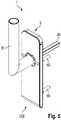
- the fitting 1 has a fitting body 2 according to the invention, a handle 30, a transmission element 26 and fastening elements 60.
- the handle 30 is designed as a door handle.
- the handle 30 has a connecting piece 32 for abutment with a fitting body 2 and an angled piece 32 of the connecting piece 31.
- the transmission element 26 serves to be inserted into a nut of a lock and to transmit a torque of the handle 30 to the lock and thus to actuate a latch and / or a bolt.
- an end 90 of the transmission element of the nut is adapted.
- the fasteners 60 are used to attach the fitting 1 to a building door.
- the handle 30 can take various positions.
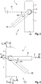
- the handle 30 may assume a first leftward orientation V, as in FIG FIG. 3 shown.
- the handle 30 may be moved from the first orientation V to a second rightward orientation VI, which is shown in FIG FIG. 4 is shown, change.
- the fitting 1 must be at least partially dismantled.
- the handle 30 can in each case only between a rest position I, as in FIG. 3 for the first orientation and in FIG. 4 shown for the second orientation with solid lines, and an operating position II, as in FIG. 3 for the first orientation and in FIG. 4 for the second alignment shown with dashed lines.
- the positions of the handle 30 which can be received in the assembled operational state are referred to as operating positions.
- An operating angle BW is the angle between the rest position of the handle and the operating position defined the handle.
- the operating angle can be 45 °.
- a mounting position III of the handle 30 is shown, which is not ingestible in a mounted state of the fitting 1. The mounting position III is taken both during a first assembly of the fitting 1 and during a change of orientation of the handle 30.
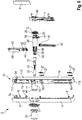
- FIG. 6 Parts of a fitting body 2 according to the invention are shown in an exploded view.
- the fitting body 2 is formed with a front side 101, a back side 102 and side surfaces 103, 104, 105, 106, as in FIGS Figures 1 and 2 shown.
- the fitting body 2 has a carrier 10.
- the carrier body is formed with a front side 111, a rear side 112 and sides 113, 114, 115, 116.
- the carrier 10 is monolithically formed from a metal.
- the carrier 10 has a carrier body 19 and a bearing element 11.
- the bearing element 11 protrudes forward from the carrier body 19.
- the bearing element 11 serves to support the handle 30.
- the bearing element is received in the handle 30.
- a bearing sleeve 33 is provided, which serves for the haptic pleasant operation of the handle 30 and to reduce the wear of the handle 30 and the bearing element 11.
- the diaphragm 9 is composed of diaphragm elements 3, 4, 5 and another, in FIG. 1 shown aperture element 49, which is used in the aperture element 5, together.
- the diaphragm elements 3, 4, 5, 49 and the cover elements 6, 7 are each formed separately from each other.
- the fitting 1 is designed as an electromechanical fitting 1.
- the fitting 1 a drive 22 which is designed as an electric motor, on. Via a spindle 23, the drive 22 moves a coupling element 24, which is guided in a mounting element 20, as in the FIGS. 7 and 8th shown.
- the coupling element 24 can be in an engaged position X, the in FIG. 7 is shown to be moved. In the engaged position X, the coupling element 24 engages in an opening 73 of a counter-coupling element 25 of the fitting body 2. In this case, the counter-coupling element 25 circumferentially surrounds the coupling element 24.
- the mounting member 20 and the handle 30 are rotatably connected to each other, in particular toothed, as in the FIGS. 9 and 10 shown. Because the coupling element 24 is guided in the installation element 20, the coupling element 24 moves with a rotation of the handle 30 from a rest position I into an actuation position II with the handle 30. Thus, a torque from the handle 30 transmits to the coupling element 24. If the coupling element 24 engages in the counter-coupling element 25, the torque can be transmitted to the counter-coupling element 25 and to the non-rotatably connected to the counter-coupling element 25 transmission element 26. Thus, upon actuation of the handle 30, the torque may act on the lock.
- a clearance between the coupling element 24 and the counter-coupling element 25 is provided. Therefore, it may be that the user first has to move the handle 30 before, in the engaged position X, the coupling element 24 transmits a torque to the counter-coupling element 25.
- a disengaged position XI which in FIG. 8 is shown, the coupling element 24 is disengaged from the counter-coupling element 25. Even in the disengaged position XI, the handle 30 can be actuated. The coupling element 24 also rotates with the handle 30 in the disengaged position XI. However, a torque in the disengaged position XI can not be transmitted to the counter-coupling element 25. Thus, a movement of the handle 30 has no effect on the lock.
- FIG. 8 an intermediate position XII of the coupling member 24 is shown in dashed lines, in which the coupling element 24 is located when the drive 22 tries to move the coupling element 24 in the engaged position X, However, due to an already made rotation of the coupling element 24 can not engage in the counter-coupling element 25, but abuts the counter-coupling element 25.
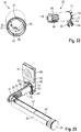
- the drive 22 and a in FIG. 23 illustrated battery compartment 34 received in the handle 30.
- the battery compartment 34 serves to store energy storage 57, in particular batteries or accumulators, in an operational state of the fitting 1, with the aid of which the drive 22 can be supplied with electrical power.
- the coupling element 24 is at least partially in the handle 30, as in the FIGS. 7 and 8th shown.
- the handle 30 is designed to be hollow.
- the coupling element 24, the counter-coupling element 25, the transmission element 26 and the handle 30 are located on a common axis 120.
- the drive 22, a motor pocket 21 for the drive 22 and the coupling element 24 are received in the mounting element 20, as in the FIGS. 7 to 10 shown.
- the mounting element 20 is rotatably mounted in the hollow bearing element 11. In this case, the mounting element 20 projects beyond the bearing element 11 to the front, as in FIG. 15 represented so that positive locking means 96 of the mounting element 20 can form a positive connection with positive locking means 58 of the handle 30, as in the FIGS. 9 and 10 shown.
- the mounting member 20 is also partially disposed in the hollow handle 30 here.
- the mounting element itself has a through hole 118 for supporting the motor bag 21 with the drive 22 and for guiding the coupling element 24, as in the FIGS. 7 . 11 and 22 shown. In this case, the passage opening 118 is in each case partially adapted to the motor pocket 21 or the coupling element 24.
- the counter-coupling element 25 is received directly in a mating coupling element receptacle 63 of the carrier 10 for the counter-coupling element 25.
- the fitting 1 has a transmitting and receiving unit with which an authentication code can be received wirelessly.
- the transmitting and receiving unit may be an antenna 51, which in FIG. 23 is shown schematically.
- the authentication code can be transmitted from an external portable authentication transmitter to the transmitting and receiving unit.
- a control unit 56 which is arranged on a printed circuit board 50, checks the authentication code and compares it with a comparison code or a default.
- the control unit 56 is in FIG. 23 covered by the board 68 and therefore shown only dashed. If the authentication code and the comparison code match or if the authentication code corresponds to the specification, the control unit 56 causes the drive 22 to move the coupling element 24 in the direction of the engaged position X.
- the control unit controls and / or controls the drive 22.
- the antenna 51 is arranged on a circuit board 68. As in the FIGS. 15 and 17 shown, the board is arranged with the antenna 51 within the carrier 10. In this way, a particularly flat fitting 1 can also be achieved.
- the carrier 10 on three side surfaces 103, 104, 105 visible.
- material for the aperture 9 can be saved.
- three sides 113, 114, 115 of the carrier 10 are completely visible.
- the carrier 10 adjoins the visible side surfaces 103, 104, 105 directly to the aperture 9.
- the panel 9 terminates flush with the carrier 10 on the visible sides 113, 114, 115.
- the carrier 10 is invisible on the front side 101 and does not need to be surface treated on the front side 111 for aesthetic reasons.
- the lower side 116 of the carrier 10 is completely covered.
- the lower side surface 106 is rounded.
- An upper first diaphragm element 3 and a lower second diaphragm element 4 are fastened to the carrier 10 via a positive and / or non-positive connection. in this connection This results in the form and / or adhesion within the carrier 10. This can be dispensed with visible in the installed state of the fitting 1 grub screws for fixing the aperture elements 3, 4.
- the first panel member 3 is formed as a flat plate, from the form and / or frictional engagement means 8 protrude rearwardly, as in the FIGS. 6 and 16 shown.
- the second panel member 4 is designed as a bent only in one end plate, protrude from the form and / or frictional engagement means 8 back executed.
- the second diaphragm element 4 is made of metal. During production, the second panel element 4 only has to be bent and not deep-drawn. Thereafter, the form and / or adhesion means 8 can be welded. As a result, a particularly inexpensive production is possible.
- the first diaphragm element 3 covers the antenna 51.
- the first diaphragm element 3 is made of a plastic.
- the first panel element 3 is clipped into the carrier 10.
- the carrier 10 corresponding receptacles 97, as in FIG. 16 shown on.
- the connection between the first panel element 3 and the carrier 10 can only be detached from the rear side 112 of the carrier 10. As a result, the first panel element 3 can not be removed by an unauthorized user.
- the first cover 6 which covers the antenna 51, made of plastic.
- the first cover element 6 is glued to the rear side 112.
- the first cover element 6 projects beyond the rear side 112 of the carrier 10. In this way, an electrically conductive connection between the carrier 10 and a metallic building door in the region of the antenna 51 can be avoided.
- the carrier 10 in the region of the antenna 51 has an electronic receptacle 13 configured as a passage opening.
- the electronics holder 13 serves as a receptacle for the circuit board 68 and the circuit board 50.
- the carrier 10 has a gap 84, through which an electrically conductive connection is interrupted around the antenna 51, as in the FIGS. 6 . 15 and 16 shown.
- the circuit board 68 with the antenna 51 is formed electrically insulated from the carrier 10.
- the antenna 51 is attached only to the carrier 10 via the circuit board 50, as in FIGS FIG. 15 and 17 shown.
- the printed circuit board 50 and the antenna 51 are connected to each other via electrically conductive connections.
- the board 68 on an unillustrated antenna element for receiving the comparison code or the default. Signals are received at a higher frequency than the antenna 51 via the antenna element.
- the second cover member 7 is reversibly releasably attached to the carrier 10, in particular screwed. As a result, a non-destructive access to the behind the second cover element 7 lying elements 40, 41, 42, 20, 25, 43 is possible. It can be provided for recesses on the cover 7 and the carrier 10, which can accommodate fastening means such as screws for releasably attaching the cover 7 to the carrier 10.
- the first and the second panel element 3, 4 enclose the handle 30 less than half, so that the first and the second panel element 3, 4 can be removed from the fitting body 2, without the handle 30 must be disassembled.
- the second panel member 4 is attached via a positive and non-positive connection to the carrier 10, which is releasable by vertical, downwardly directed displacement.
- the carrier 10 in recordings 99 of the carrier 10, in the FIGS. 6 and 25 are shown, spring washers 27 which in the FIGS. 6 and 16 are shown, inserted, in which the form and / or adhesion means 8 of the second diaphragm element 4 can intervene.
- the form and / or adhesion means 8 of the second diaphragm element 4 are formed as provided with a mushroom head pins.
- the spring washers 27 are in a lower Passable area for the mushroom heads.
- the mushroom heads are held positively in front, while the spring washers 27 clamp the mushroom heads such that the second diaphragm element 4 is held. If the clamping force is overcome by a user, the user can move the second diaphragm element 4 downwards and then remove it.
- the carrier 10 has in the region of the second diaphragm element 4 door mounting receptacles 14, 15, as in FIG. 25 shown on.
- the fasteners 60 are accessible.
- the fasteners 60 may be detachable only from the rear side 112 of the carrier 10.
- an emergency lock cylinder (not shown) behind the second panel element 4.
- a securing element (not shown) may be arranged under the form and / or force-locking means 8 of the second diaphragm element 4 and prevent a displacement of the second diaphragm element 4 by a positive connection.
- an opening 98 for a lock cylinder may be formed in the second panel element 4, as in FIG FIG. 15 shown. The lock cylinder (not shown) can protrude through the opening in a built-in state of the fitting 1 and prevent downward displacement of the second panel element 4.
- the first and the second diaphragm element 3, 4 on a continuous surface.
- the carrier 10 has a lock cylinder receptacle 12, as in the FIGS. 6 and 25 shown.
- the designed as a through hole lock cylinder receptacle 12 is dimensioned such that a lock cylinder can be pushed through at different distances to the handle 30.
- the emergency lock cylinder can be completely hidden behind the second aperture element 4. Otherwise, the lock cylinder can protrude through the second diaphragm element 4, wherein the opening 98 of the second diaphragm element 4 is adapted to the size of the lock cylinder.
- second aperture elements 4 For different distances from lock cylinders to the handle 30 second aperture elements 4 must be kept with corresponding openings 98. However, the remaining fitting 1 does not have to be adapted to the different distances between a lock cylinder and the handle 30.
- the corresponding door fastening receptacle 14, 15 can be designed such that the fastening elements 60 can be variably placed.
- the door mounting receptacles 14 are each configured as a slot, as in FIG. 25 shown.
- the first panel member 3 and the first cover member 6 form a protective downwardly open housing around the board 68. As in FIG. 25 shown, the housing is open at the bottom, so that air circulation is achieved. As in FIG. 6 and 16 illustrated, the first panel member 3 an angled protection means 74 which is arranged in the gap 84. The gap 84 is formed rising from outside to inside.
- electrical conductors 37, 38, 91, 92 are shown.
- the first electrical conductors 37, 38 are arranged in the handle 30 and designed to transport electric current from two poles of the energy store 57.
- the first electrical conductors 37, 38 lead through the handle 30 from the battery compartment 34 to the printed circuit board 50. Further lead from the printed circuit board 50 second electrical conductors 91, 92 to the drive 22.
- the first electrical conductors 37, 38 supply the printed circuit board 50 with electricity.
- the first and second electrical conductors 37, 38, 91, 92 are mechanically interconnected within the connector 32, with the electrical conductors 37, 38, 91, 92 isolated from each other. This applies in particular to the area in which the mounting element 20 is arranged.
- the installation element 20 supports the first and second electrical conductors 37, 38, 91, 92.
- the installation element 20 has a boundary region 95.
- the restriction region 95 is designed as a smooth section of a cylinder jacket surface.
- the limiting region 95 is designed in such a way that the electrical conductors 37, 38, 91, 92 rest against the limiting region 95 in each operating position of the handle, as in FIGS FIGS. 9 and 10 shown. This applies to both the first and the second orientation V, VI.
- the interlocking means 96 are not formed around the entire periphery of the installation member 20, as in FIGS FIGS. 9, 10 and 22 shown.
- the interlocking means 58 are interrupted as in FIGS FIGS. 9, 10 and 22 shown to form a region for guiding the electrical conductors 37, 38, 91, 92.
- the interlocking means 58 are interrupted twice, so that for both the first and the second orientation V, VI of the handle 30, a region for guiding the electrical conductors 37, 38, 91, 92 results.
- the electrical conductors 37, 38, 91, 92 are arranged rotationally fixed.
- a guide 93 is provided, which is formed laterally from a passage 94 of the bearing element, which in the FIGS. 9, 10 and 26 is shown. Above the guide 93 is limited by the bearing sleeve 33. At the bottom, the boundary portion 95 closes the guide 93, as in FIGS FIGS. 9 and 10 shown.
- the battery compartment 34 is disposed in the handle 31.
- the energy storage 57 can be replaced by removing a cover 25.
- the lid 35 can only be opened via a special tool.
- the battery compartment 34 ends in front of the cover 35.
- the battery compartment 34 is dimensioned such that the energy storage 57 projects beyond the battery compartment 34 into the cover 35.
- the cover 35 is provided for the electrical conduction of the electrical current of at least one energy store 57.
- the cover 35 is adapted to the circumference of the energy store 57 such that a secure hold of the energy store 57 and a secure electrical contact with the lid 35 are possible.
- a planar projection in the cover 35 and a circumference of the cover 35 are adapted to one another such that the energy store 57 contacts a pole of the energy store 57 even if the movement of the energy store 57 is radial relative to an axis of the handle 31.
- the energy storage 57 can rest against a flat projection of the lid 35 even with a shaking movement.
- the cover 35 is electrically connected to the negative pole of the energy storage 57.
- an electrical conductor 36 in particular a metal strip 36 is provided. This is disposed inside the handle 31 of the handle 30, and passes the electric current from the lid 35 to the battery compartment 34 over.
- the electrical conductor 36 is designed spring-loaded and is in particular resiliently against the cover 35.
- the electrical conductor 36, in particular the metal strip 36 is formed such that upon insertion of the lid 35 into the handle 31 of the electrical conductor 36 is increasingly elastically bending.
- a spring element 59 is arranged in the battery compartment 34, which exerts a mechanical force for fixing to the energy storage 57 and presses the energy storage 57 in particular against the cover 35.
- a shoulder is provided in the handle 31 against which the battery compartment 34 abuts.
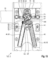
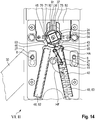
- FIGS. 11 to 14 are rear views of the fitting 1 from the FIGS. 3 and 4 shown, wherein the FIGS. 11 and 12 a first orientation V of the handle 30 and the Figures 13 and 14 a second orientation VI of the handle 30 correspond.
- each of the transmission element 26, the counter-coupling element 25 and the cover 7 are not shown, so that the fitting 1 is shown partially open.
- the fitting body 2 a spring 40.
- the spring 40 serves to move the handle 30 in the rest position I.
- the spring 40 is connected via a lever 42 indirectly with the handle 30.
- the spring 40 is designed as a compression spring.
- the lever 42 is connected via an extension with the handle 30.
- the extension corresponds to a stop element 43.
- the stop element 43 is part of the monolithic built-in element 20 and thus rotatably and reversibly releasably connected to the handle 30.
- the lever 42 is inserted in the stop element 43 and thus rotatably supported.
- the lever 42 is mounted in the first orientation V of the handle 30 in a first bearing 64 of the stop member 43 and the second orientation VI of the handle 30 in a second bearing 65 of the stop member 43, as in the FIGS. 11 to 14 shown.
- lever 42 Another end of the lever 42 is connected via a spring carriage 41 with the spring 40, in particular clipped.
- the lever 42 is in this case rotatably mounted in the spring carriage 41.
- the spring 40 is mounted in a first spring retainer 82 at the first orientation V of the handle 30 as in FIGS FIGS. 11 and 12 shown. Accordingly, the spring 40 is mounted in a second spring retainer 83 in the second orientation of the handle 30, as in the Figures 13 and 14 shown.
- the thickness of the fitting body 2 is predetermined.
- the thickness corresponds to the spring retainer 82, 83 and the thickness of the aperture 9 of the thickness of the fitting body 2, as in FIG. 17 shown.
- the spring receptacle 82, 83 further acts to guide the spring carriage 41.
- the lever 42 is guided via the spring carriage 41 on the spring receptacle 82, 83, wherein the spring carriage 41 slides along the spring receiver 82, 83.
- a movement of the lever 42 is predetermined.
- the lever 41 is so connected to the spring 40 and the stopper member 43 that during movement from the operating position II to the rest position I, an angle HF between the spring 40 and the lever 41 and an angle HA between the lever 41 and the stopper member 43rd reduce so that the force acting on the handle 30 by the spring 40, the lever 41 and the stopper torque in the rest position I is greater than in the operating position II. In this way, the handle 30 can be particularly effectively held in rest position I. Further, this is overcompensated during the movement of the handle 30 from the operating position II in the rest position I decreasing spring force of the spring 40.
- the decreasing angles HF and HA are between 180 ° and 90 ° during a movement from the actuation position II to the rest position I.
- the angle HA is reduced to less than 90 ° during a movement from the actuation position II to the rest position I. This results in a wave-shaped torque curve for the torque acting on the handle 30 by the spring 40, the lever 41 and the stop element 43.
- the first part 48 of the spring receptacle 82, 83 is covered by the cover member 7, whereby the cover member 7 forms a second part 62 of the respective spring retainer 82, 83.
- the spring receivers 82, 83 are divided by a longitudinal division.
- the first part 48 of the Federfactn 82, 83 configured so open that the spring 40 can be easily mounted, disassembled or relocated from a spring retainer 82, 83 in the other spring retainer 82, 83.
- the carrier has a first stop 46 and a second stop 47.
- the stops 46, 47 serve to limit a movement of the handle 30 in the mounted state.
- the stop member 43 In the first orientation V of the handle 30, the stop member 43 is in the rest position I to the second stop 47 and in the operating position II on the first stop 46, as in the FIGS. 11 and 12 shown.
- the stop member 43 In the second orientation VI of the handle 30, the stop member 43 is in the rest position I on the first stop 46 and in the operating position II on the second stop 47, as in the Figures 13 and 14 shown.
- the same stops 46, 47 limit the movement of the spring 40 in both the first and in the second orientation V, VI of the handle 30.
- the stops 46, 47 are symmetrical to a longitudinal plane LE of the fitting first
- a stop angle AW is determined by the position of the stop element 43 in the rest position I at the first orientation V and by the position of the stop element 43 in the rest position I at the second orientation VI, as in FIG. 11 shown, given.
- the stop angle AW corresponds to the operating angle BW.
- the handle 30 is reversibly releasably connected to the stop element 43.
- the mounting element 20 on the outer circumference of the mounting member 20 has a toothing, which engages in a toothing on an inner side 81 of the handle 30, as in the FIGS. 9 and 10 shown.
- the stop element 43 is arranged in the rest position I offset at the first orientation V by the stop angle AW relative to the rest position I in the second orientation VI. Due to the fact that the handle 30 rotates by 180 ° when changing from one orientation V, VI to the other orientation V, VI, an offset angle VW of 180 ° -AW results, with which the stop element 43 moves with respect to the handle 30 at a Change from the first orientation V to the second orientation VI is to be rearranged.
- an angle between the teeth of the teeth ZW has been selected with an integer divisor of the offset angle VW, as in the FIGS. 9 and 10 shown.
- the divider is exemplary 6.
- the coupling element 24 is at a first orientation V of the handle 30 relative to a second orientation VI of the handle 30 in the rest position I also offset by the stop angle AW, as can be seen by a comparison of the Figures 11 and 13 results. Accordingly, the counter-coupling element 25 is also offset by the stop angle AW in the first orientation V of the handle 30 relative to the second orientation VI of the handle 30, inserted into the carrier 10.
- the mating coupling receptacle 63 is configured in the carrier 10 by way of example such that the mating coupling element 25 is freely rotatable.
- the transmission element 26 is reversibly detachably connected to the counter-coupling element 25.
- the transmission element 26 retains its alignment both in the first orientation V and in the second orientation VI of the handle 30 so that the transmission element 26 can be inserted into the nut of the lock.
- the counter-coupling element 25 can be inserted into the transmission element 26 in at least two positions, so that the counter-coupling element 25 is rotatable when the orientation V, VI is changed, whereas the transmission element 26 retains its orientation.
- the counter-coupling element 25 is offset by the stop angle AW in the transmission element 26 can be used.
- the counter-coupling element 25 and the transmission element 26 are interlocked.
- an integer divider of the stop angle AW has been selected as the angle between two teeth of the teeth ÜZ.
- the divider is exemplary 2.
- the stopper member 43 is disposed between the rear side 112 of the carrier 10 and the second cover member 7.
- the stop element 43 is in an installed state of the fitting 1 for an unauthorized user Inaccessible arranged. Rather, the fitting 1 must first be dismantled from the building door before the stop element 43 is accessible.
- the stop member 43 limits movement of the handle 30 by abutment against the stops 46, 47 on the operating positions, the handle 30 can not be transferred to the mounting position III in the installed state of the fitting. Only when the fitting 1 is dismantled from the building door and the second cover 7 is released from the carrier 10, the stop member 43 is accessible.
- the stopper member 43 is removed by pulling the installation member 20 out of the carrier 10. Thereafter, the handle 30 occupy the mounting position III.
- the handle 30 In the mounting position III, the handle 30 is axially movable along the bearing element 11. Thus, the handle 30 can be disassembled from the fitting body 2. In the operating positions, however, the handle 30 is held on the bearing element 11 peel-off rotatably. Thus, disassembly of the handle 30 is prevented in the operating positions.
- the handle 30 has a first connecting element 39 and the bearing element 11 has a second connecting element 18.
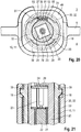
- the connecting elements 18, 39 are shown, wherein in FIG. 21 a rest position I as an operating position and in FIG. 20 the mounting position III is shown.
- the connecting elements 18, 39 are each designed as projections. As in FIG. 21 shown, in the operating positions, the first connecting element 39 is separated by the bearing sleeve 33 behind the second connecting element 18, so that the first connecting element 39 prevents by a positive connection with the second connecting element 18 that the handle 30 can be withdrawn from the bearing element 11.
- the first connecting element 39 is formed on the inner side 81 of the handle 30, as in the FIGS. 20 to 22 shown.
- the second connecting element 18 is formed on the outside of the bearing element 11, as in the FIGS. 6 . 21 and 26 shown.
- the peel-resistant rotatable connection of the handle 30 with the bearing element 11 within the handle 30 takes place.
- the handle 30 rotatably connected both via the mounting member 20 with the coupling member 24 as well as on the bearing element 11 peelable rotatable within the handle 30, it is possible to dispense with externally visible grub screws in the region of the handle 30.
- the fact that the diaphragm 9 is fixed free of setscrews, it is possible to make the fitting 1 free of visible in the installed state grub screws.
- a first end 80 of the handle 30 terminates in front of the carrier body 19, as in FIG. 7 and 8th shown.
- the carrier 10 guides the handle 30 only via the bearing element 11.
- a lateral surface 17 of the cylindrical bearing element 11 is configured without passage opening. Due to the continuous configuration of the bearing element 11, the bearing element 11 is sufficiently stable to absorb forces of the handle 30 can.
- the first and the second connecting element 18, 39 are arranged one behind the other such that a 360 ° rotation of the handle 30 about the bearing element 11 is conceivable.
- the 360 ° rotation is undesirable because of the electrical conductors 37, 38, 91, 92.
- a rotation stop is provided.
- the rotation stop comprises a stop 66 of the bearing element 11 (s. FIG. 26 ) and a stop 67 of the handle 30, as in FIG. 22 shown.
- the stops 66, 67 are arranged behind the connecting elements 18, 39.
- the stops 66, 67 prevent a 360 ° rotation of the handle 30 in that the stops 66, 67 come into contact with each other during a rotation when the stop element 43 is disassembled.
- the second connecting element 18 extends through the bearing sleeve 33.
- the bearing sleeve 33 covers a contact surface of the second connecting element 18 the first connecting element 39 connects.
- the bearing sleeve 33 has a continuous slot 79, as in the Figures 9 and 20 shown.
- the first and second connecting elements 18, 39 are each designed as two projections.
- the second connecting element 18 is designed symmetrically to the longitudinal plane LE of the fitting 1, as in the Figures 20 and 26 shown. As in FIG. 20 shown, cover the first and the second connecting element 18, 39 together in the mounting position III more than 75% of the circumference of the bearing element 11. Due to the large-scale configuration of the connecting elements 18, 39, a good guidance of the handle 30 can be achieved on the bearing element 11.
- the connecting elements 18, 39 are arranged such that both in the first orientation V and in the second orientation VI of the handle 30, the handle 30 is held in the operating positions peel-resistant rotatable.
- the third diaphragm element 5 is arranged between the first and the second diaphragm element 3, 4.
- the third diaphragm element 5 serves as a light guide. For this purpose, it allows light from a plurality of light sources 52, which are designed as tricolor LEDs happen.
- the lighting means 52 are arranged on the printed circuit board 50, as in FIG FIG. 23 shown. Due to the different colors of the lamps 52 different states of the fitting 1 can be signaled. The different colors are used to display the user authorization, a state of charge of the energy storage and / or an operating condition of the fitting 1.
- the third panel member 5 is fixed by the handle 30 and the aperture elements 3, 4 on the fitting 1.
- the coupling element 24 In the engaged position X of the coupling element 24, the coupling element 24 is arranged at a distance from the transmission element 26 located behind the coupling element 24. In the disengaged position XI, the coupling element 24 is spaced apart from the drive 22 located in front of the coupling element 24. As a result, a locking of the coupling element 24 can be avoided.
- the counter-coupling element 25 is designed to be open, so that the coupling element 24 can engage deeply in the counter-coupling element 25 without the counter-coupling element 25 abuts against the counter-coupling element 25 in the direction of movement.
- a toothing of the counter-coupling element 25 with the transmission element 26 is radially with respect to.
- the axis 120 is formed.
- the toothing of the counter-coupling element 25 is formed around the circumference of the counter-coupling element 25, which engages in a recess of the transmission element 26. In this way, a distance of the coupling element 24 in the engaged position X to the underlying transmission element 26 can be made large.
- the counter-coupling element 25 and the transmission element 26 are designed separately from one another.
- the counter-coupling element 25 is axially fixed between the carrier 10 and the cover 7, as in the FIGS. 7 and 8th shown.
- the transmission element 26 and the counter-coupling element 25 have a mutual play, as in FIG. 18 shown.
- the transmission element 26 is mounted axially and radially with respect to the axis 120 in the second cover element 7.
- the transmission element 26 it is possible for the transmission element 26 to adapt to the position of a lock without the counter-coupling element 25 varying in alignment with the coupling element 24.
- an end of the transmission element 26 facing away from the counter-coupling element 25 is movable in several spatial directions.
- the transmission element 26 is widened at one end 89, whereby a position in the fitting body 2 and the cover 7 is possible.
- the cover 7 has a circumferential collar 86 for storage, as in the FIGS. 6 . 16 and 19 shown.
- the collar 86 has a cylinder jacket-shaped portion 87 and an adjoining tapered portion 88.
- the transmission element 26 is mounted like a ball joint. Due to the storage, the transmission element 26 with a in FIG. 17 displayed maximum Deflection angle LW be deflected from a vertical deflection. The maximum deflection angle LW can be taken in different directions in space, so that a straight circular cone, as in FIG. 19 shown, results.
- the counter-coupling element 25 and the transmission element 26 has a curved toothing, as in the FIGS. 18 and 19 you can see.
- the toothing on the counter-coupling element 25 has eight teeth. So that the counter-coupling element 25 does not impair a bearing clearance for the bearing of the transmission element 26 by the cover element 7, the diameter of the elevation with the toothing of the counter-coupling element 25 is less than the diameter of the recess with toothing of the transmission element 26.
- the toothing of the counter-coupling element 25 only in sections in contact with the toothing of the transmission element 26. Due to the curved design of the toothing, the transmission element 26 and the counter-coupling element 25 are in a torque transmission yet flat against each other.
- the fitting 1 door mounting receptacles 14, 15 only below the antenna 51.
- the first cover 6 may have a flat, continuous surface.
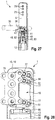
- FIGS. 27 and 28 is a further embodiment of a fitting 1 according to the invention shown, in each case only a section is shown. Unless described below, the equivalent in the FIGS. 27 and 28 shown fitting in the FIGS. 1 to 26 described fitting 1.
- the in the FIGS. 27 and 28 shown fitting 1 has a door mounting receptacle 76 above the antenna 51.
- the door attachment receptacle 76 above the antenna 51 is configured as a hole group for variably placing a fastener 60.
- the door attachment receptacle 76 is formed electrically insulated from the carrier 10. For this purpose, insulation elements 77 between the carrier 10 and the Door attachment receptacle 76 is provided.
- the carrier 10 has a receptacle 16 configured as a passage opening for arranging the door attachment receptacle 76. At the edge of the receptacle 16 fastening means 61 are provided in the carrier 10, to which the door mounting receptacle 76 can be attached.
- a further gap 85 is provided in the fitting 1 for the reduction of electrical currents.
- the gap 85 lies in the interior of the carrier 10, as in FIG FIG. 28 shown.
- the first cover member 6 openings 78 for the passage of the fastener 60.
- the openings 78 in the salable state are only pre-cut (not shown), so that when necessary to open a door to the opening 60 required for the fastener 60.
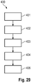
- FIG. 29 an inventive method 400 for dismantling a fitting 1 is shown.
- a lock cylinder which projects through an aperture element 4, which covers the fastening elements 60, is removed from the fitting 1. As a result, the diaphragm element 4 is displaced downwards.
- a second method step 402 the diaphragm element 4 is moved downward.
- a clamping force which has held the diaphragm element 4 in a fitting body 2 of the fitting 1, overcome.
- Shaping and / or adhesion means 8 of the diaphragm element 4 now also allow movement of the diaphragm element 4 forward.
- the method step 402 corresponds to an exemplary embodiment of the step a.
- step 403 the diaphragm element 4 is removed from the fitting body 2.
- the further diaphragm elements 3, 5, 49 remain on the fitting body 2.
- the handle 30 remains on the fitting body 2.
- the method step 403 corresponds to a Embodiment of step b. Now the fasteners 60 are accessible to the user.
- Method step 404 corresponds to an exemplary embodiment of step c.
- step 405 the fitting 1 is removed from the building door.
- the method steps 404 and 405 can also be performed simultaneously.
- the method step 401 is optional.
- no locking cylinder protruding through the shutter member 4 is present, so that the process step 402 can be started directly.
Landscapes
- Lock And Its Accessories (AREA)
Claims (15)
- Corps de ferrure (2) pour une ferrure (1) pour une porte de bâtiment,
avec une face avant (101), une face arrière (102) et des surfaces latérales (103, 104, 105, 106), la face arrière (102) servant à l'agencement sur la porte de bâtiment,
le corps de ferrure (2) présentant un support (10) et un écran (3, 4, 5) pour le recouvrement du support (10) au moins sur la face avant (101), l'écran (3, 4, 5) étant subdivisée en au moins un premier élément écran (3) et un deuxième élément écran (4), au moins un élément écran (3, 4) étant attaché sur le support (10) par une connexion par la forme et/ou par la force, l'élément écran attaché par une connexion par la forme et/ou par la force sur le support étant détachable de façon réversible,
caractérisée en ce
qu'une connexion par la forme et/ou par la force avec laquelle l'élément écran (3, 4) est attaché au support (10) est détachable par déplacement, l'élément écran (3, 4) étant attaché au support (10) par une connexion serrée. - Corps de ferrure (2) selon la revendication 1,
caractérisé en ce que l'élément écran (3, 4) est attaché à l'intérieur du corps de ferrure (2). - Corps de ferrure (2) selon la revendication 1 ou 2,
caractérisé en ce que l'élément écran (3, 4) entoure tout au maximum une moitié d'une surface d'application du corps de ferrure (2) prévue pour une manette (30). - Corps de ferrure (2) selon l'une des revendications précédentes,
caractérisé en ce que le premier et le deuxième éléments écran (3, 4) sont attachés au support (10) par une connexion par la forme et/ou par la force. - Corps de ferrure (2) selon l'une des revendications précédentes,
caractérisé en ce que l'élément écran (3, 4) recouvre au moins une réception d'd'attachement de porte (14, 15, 16) du corps de ferrure (2) pour la réception d'un élément d'attachement (60) pour l'attachement sur la porte de bâtiment et/ou une réception de cylindre de fermeture (12) du corps de ferrure (2) pour la réception d'un cylindre de fermeture, tout particulièrement la réception d'attachement de porte (14, 15, 16) et/ou la réception du cylindre de fermeture (12) sont aménagés de telle façon que l'élément d'attachement (60), respectivement le cylindre de fermeture sont positionnable variablement dans la réception d'attachement de porte (14, 15, 16), respectivement la réception de cylindre de fermeture (12). - Corps de ferrure (2) selon l'une des revendications précédentes, caractérisé en ce que les éléments écran (3, 4) présentent une surface plane continue formant la face avant (101).
- Corps de ferrure (2) selon la revendication 5,
caractérisé en ce que le deuxième élément écran (4) lequel sert au recouvrement de la réception du cylindre de fermeture (12) présente une ouverture de cylindre de fermeture (98) adaptée à la dimension du cylindre de fermeture. - Corps de ferrure (2) selon l'une des revendications précédentes,
caractérisé en ce que le premier élément écran (3), lequel sert tout particulièrement au recouvrement d'une unité de contrôle pour un contrôle d'autorisation d'accès, est attaché de telle façon par la forme et/ou par la force au support (10) que le premier élément écran (3) est détachable seulement à partir de la face arrière (102). - Corps de ferrure (2) selon l'une des revendications précédentes,
caractérisé en ce que, dans la condition montée, le deuxième élément écran (4) est prévu à être agencé de façon non-détachable à partir de la face avant (101) et des surfaces latérales (103, 104, 105, 106), tout particulièrement une ouverture de cylindre de fermeture (98) étant pénétrable pour un cylindre de fermeture, et/ou au moins un élément de sécurisation agencé dans le corps de ferrure (2) empêche un détachement du deuxième élément écran (4). - Corps de ferrure (2) selon l'une des revendications 1 à 8,
caractérisé en ce que le deuxième élément écran (4) est agencé à être détachable à partir de la face avant (101) ou à partir des surfaces latérales (103, 104, 105, 106). - Corps de ferrure (2) selon l'une des revendications précédentes,
caractérisé en ce que l'élément écran (3, 4) est aménagé comme une plaque plane ou un plaque courbée sur une extrémité seulement, à partir de laquelle un élément de connexion par la forme et/ou par la force fait saillie vers l'arrière. - Corps de ferrure (2) selon l'une des revendications précédentes,
caractérisé en ce que l'élément écran (3, 4) est aménagé avec une épaisseur dans une plage entre 1,0 mm et 3,0 mm, de préférence dans une plage entre 1,5 mm et 2,5 mm, tout particulièrement préféré dans une plage entre 1,8 mm et 2,2 mm. - Ferrure (1) avec un corps de ferrure (2) et avec une manette (30) selon l'une des revendications précédentes.
- Méthode pour le démontage d'une ferrure (1) selon la revendication 13, comprenant les étapes suivantes :a. déplacement d'un élément écran (3, 4) de sorte que l'élément écran (3, 4) déplacé devient amovible,b. détacher l'élément écran (3, 4) déplacé du corps de ferrure (2), la manette (30), tout particulièrement une poignée de porte, et/ou un autre élément écran (3, 4) restant sur le corps de ferrure (2),c. desserrer au moins un élément d'd'attachement lequel sert à l'attachement sur la porte de bâtiment.
- Garniture de ferrures avec des ferrures (1) selon la revendication 13, les ferrures (1) servant à l'agencement sur des faces opposées de portes de bâtiment.
Priority Applications (2)
| Application Number | Priority Date | Filing Date | Title |
|---|---|---|---|
| EP14185841.5A EP2998468B1 (fr) | 2014-09-22 | 2014-09-22 | Corps d'armature pour une armature et procédé |
| DE102015109910.1A DE102015109910A1 (de) | 2014-09-22 | 2015-06-19 | Beschlagskörper für einen Beschlag und Verfahren |
Applications Claiming Priority (1)
| Application Number | Priority Date | Filing Date | Title |
|---|---|---|---|
| EP14185841.5A EP2998468B1 (fr) | 2014-09-22 | 2014-09-22 | Corps d'armature pour une armature et procédé |
Publications (2)
| Publication Number | Publication Date |
|---|---|
| EP2998468A1 EP2998468A1 (fr) | 2016-03-23 |
| EP2998468B1 true EP2998468B1 (fr) | 2018-12-26 |
Family
ID=51585016
Family Applications (1)
| Application Number | Title | Priority Date | Filing Date |
|---|---|---|---|
| EP14185841.5A Active EP2998468B1 (fr) | 2014-09-22 | 2014-09-22 | Corps d'armature pour une armature et procédé |
Country Status (2)
| Country | Link |
|---|---|
| EP (1) | EP2998468B1 (fr) |
| DE (1) | DE102015109910A1 (fr) |
Family Cites Families (8)
| Publication number | Priority date | Publication date | Assignee | Title |
|---|---|---|---|---|
| DE1272158B (de) * | 1964-08-12 | 1968-07-04 | Schuermann & Co Heinz | Drueckerbefestigung, insbesondere fuer Metallrahmentueren, -fenster od. dgl. |
| DE8609367U1 (de) * | 1986-04-07 | 1986-07-17 | Peter Metz, Homa-Beschläge GmbH & Co KG, 5620 Velbert | Beschlagbefestigung |
| FI92091C (fi) * | 1992-04-10 | 1994-09-26 | Abloy Security Ltd Oy | Ovikilpijärjestelmä |
| US6244084B1 (en) * | 1998-02-27 | 2001-06-12 | Tod L. Warmack | Remote control lock device |
| US7984631B2 (en) * | 2003-12-22 | 2011-07-26 | Yale Security Inc. | Modular escutcheon |
| AT7368U1 (de) | 2004-02-06 | 2005-02-25 | Kaba Gmbh | Beschlag |
| DE202005008396U1 (de) * | 2005-05-25 | 2005-08-04 | SCHÜCO International KG | Zustandsüberwachungseinrichtung für Griffbeschläge für Fenster oder Türen |
| PL214410B1 (pl) * | 2006-04-07 | 2013-07-31 | Fakro Pp Spolka Z Ograniczona Odpowiedzialnoscia | Klamka, zwlaszcza okienna |
-
2014
- 2014-09-22 EP EP14185841.5A patent/EP2998468B1/fr active Active
-
2015
- 2015-06-19 DE DE102015109910.1A patent/DE102015109910A1/de not_active Withdrawn
Non-Patent Citations (1)
| Title |
|---|
| None * |
Also Published As
| Publication number | Publication date |
|---|---|
| DE102015109910A1 (de) | 2016-03-24 |
| EP2998468A1 (fr) | 2016-03-23 |
Similar Documents
| Publication | Publication Date | Title |
|---|---|---|
| DE102018202563B4 (de) | Knauf für einen elektronischen Schließzylinder | |
| EP3482024A1 (fr) | Dispositif de préhension comprenant une poignée à fleur | |
| EP3111029B1 (fr) | Système de poignée de porte pour véhicules | |
| WO2019011527A1 (fr) | Système de poignée de porte d'un véhicule automobile | |
| EP2998483A1 (fr) | Bouton rotatif destiné à actionner un adaptateur de cylindre d'un barillet | |
| EP3317481A1 (fr) | Système de poignée de porte pour véhicules | |
| EP2998485B1 (fr) | Bouton rotatif destine a actionner un adaptateur de cylindre d'un barillet | |
| EP2998484B1 (fr) | Armature pour une porte de bâtiment | |
| EP3000952B1 (fr) | Composant de fixation sur un mecanisme de fermeture d'une porte ou d'une fenetre | |
| EP2998465B1 (fr) | Armature pour une porte de bâtiment et procédé associé | |
| EP2998463B1 (fr) | Armature pour une porte de bâtiment et procédé | |
| EP2998466B1 (fr) | Armature pour une porte de bâtiment | |
| EP2998468B1 (fr) | Corps d'armature pour une armature et procédé | |
| EP2998470B1 (fr) | Armature pour une porte de bâtiment | |
| EP2998479B1 (fr) | Armature pour une porte de bâtiment dotée d'une poignée | |
| DE102015111937A1 (de) | Drehknauf zum Betätigen eines Zylinderadapters eines Schließzylinders | |
| EP2998486A1 (fr) | Bouton rotatif destine a actionner un adaptateur de cylindre d'un barillet | |
| EP2998469B1 (fr) | Armature pour une porte de bâtiment | |
| EP2998464B1 (fr) | Armature pour une porte de bâtiment | |
| EP1705320A1 (fr) | Poignée d'actionnement | |
| EP2998482A1 (fr) | Bouton rotatif destiné à actionner un adaptateur de cylindre d'un barillet | |
| EP2998481B1 (fr) | Système de contrôle d'accès électromécanique | |
| DE102015111943A1 (de) | Drehknauf zum Betätigen eines Zylinderadapters eines Schließzylinders | |
| DE102011100405B4 (de) | Befestigungsvorrichtung, Rahmenteil und Schwenkteil | |
| WO2026052457A1 (fr) | Dispositif de capuchon de protection, appareil de fermeture, appareil de fermeture de protection contre la poussière et appareil de fermeture |
Legal Events
| Date | Code | Title | Description |
|---|---|---|---|
| PUAI | Public reference made under article 153(3) epc to a published international application that has entered the european phase |
Free format text: ORIGINAL CODE: 0009012 |
|
| AK | Designated contracting states |
Kind code of ref document: A1 Designated state(s): AL AT BE BG CH CY CZ DE DK EE ES FI FR GB GR HR HU IE IS IT LI LT LU LV MC MK MT NL NO PL PT RO RS SE SI SK SM TR |
|
| AX | Request for extension of the european patent |
Extension state: BA ME |
|
| 17P | Request for examination filed |
Effective date: 20160920 |
|
| RBV | Designated contracting states (corrected) |
Designated state(s): AL AT BE BG CH CY CZ DE DK EE ES FI FR GB GR HR HU IE IS IT LI LT LU LV MC MK MT NL NO PL PT RO RS SE SI SK SM TR |
|
| RAP1 | Party data changed (applicant data changed or rights of an application transferred) |
Owner name: DORMAKABA DEUTSCHLAND GMBH |
|
| STAA | Information on the status of an ep patent application or granted ep patent |
Free format text: STATUS: EXAMINATION IS IN PROGRESS |
|
| 17Q | First examination report despatched |
Effective date: 20171026 |
|
| GRAP | Despatch of communication of intention to grant a patent |
Free format text: ORIGINAL CODE: EPIDOSNIGR1 |
|
| STAA | Information on the status of an ep patent application or granted ep patent |
Free format text: STATUS: GRANT OF PATENT IS INTENDED |
|
| RIC1 | Information provided on ipc code assigned before grant |
Ipc: E05B 47/06 20060101ALN20180626BHEP Ipc: E05B 17/10 20060101ALN20180626BHEP Ipc: E05B 63/04 20060101ALN20180626BHEP Ipc: E05B 3/06 20060101ALN20180626BHEP Ipc: E05B 15/00 20060101AFI20180626BHEP Ipc: E05B 47/00 20060101ALN20180626BHEP Ipc: E05B 15/02 20060101ALN20180626BHEP |
|
| INTG | Intention to grant announced |
Effective date: 20180712 |
|
| GRAS | Grant fee paid |
Free format text: ORIGINAL CODE: EPIDOSNIGR3 |
|
| GRAA | (expected) grant |
Free format text: ORIGINAL CODE: 0009210 |
|
| STAA | Information on the status of an ep patent application or granted ep patent |
Free format text: STATUS: THE PATENT HAS BEEN GRANTED |
|
| AK | Designated contracting states |
Kind code of ref document: B1 Designated state(s): AL AT BE BG CH CY CZ DE DK EE ES FI FR GB GR HR HU IE IS IT LI LT LU LV MC MK MT NL NO PL PT RO RS SE SI SK SM TR |
|
| REG | Reference to a national code |
Ref country code: GB Ref legal event code: FG4D Free format text: NOT ENGLISH |
|
| REG | Reference to a national code |
Ref country code: CH Ref legal event code: EP |
|
| REG | Reference to a national code |
Ref country code: AT Ref legal event code: REF Ref document number: 1081620 Country of ref document: AT Kind code of ref document: T Effective date: 20190115 |
|
| REG | Reference to a national code |
Ref country code: IE Ref legal event code: FG4D Free format text: LANGUAGE OF EP DOCUMENT: GERMAN |
|
| REG | Reference to a national code |
Ref country code: DE Ref legal event code: R096 Ref document number: 502014010444 Country of ref document: DE |
|
| REG | Reference to a national code |
Ref country code: CH Ref legal event code: NV Representative=s name: RENTSCH PARTNER AG, CH |
|
| PG25 | Lapsed in a contracting state [announced via postgrant information from national office to epo] |
Ref country code: FI Free format text: LAPSE BECAUSE OF FAILURE TO SUBMIT A TRANSLATION OF THE DESCRIPTION OR TO PAY THE FEE WITHIN THE PRESCRIBED TIME-LIMIT Effective date: 20181226 Ref country code: LV Free format text: LAPSE BECAUSE OF FAILURE TO SUBMIT A TRANSLATION OF THE DESCRIPTION OR TO PAY THE FEE WITHIN THE PRESCRIBED TIME-LIMIT Effective date: 20181226 Ref country code: HR Free format text: LAPSE BECAUSE OF FAILURE TO SUBMIT A TRANSLATION OF THE DESCRIPTION OR TO PAY THE FEE WITHIN THE PRESCRIBED TIME-LIMIT Effective date: 20181226 Ref country code: LT Free format text: LAPSE BECAUSE OF FAILURE TO SUBMIT A TRANSLATION OF THE DESCRIPTION OR TO PAY THE FEE WITHIN THE PRESCRIBED TIME-LIMIT Effective date: 20181226 Ref country code: BG Free format text: LAPSE BECAUSE OF FAILURE TO SUBMIT A TRANSLATION OF THE DESCRIPTION OR TO PAY THE FEE WITHIN THE PRESCRIBED TIME-LIMIT Effective date: 20190326 Ref country code: NO Free format text: LAPSE BECAUSE OF FAILURE TO SUBMIT A TRANSLATION OF THE DESCRIPTION OR TO PAY THE FEE WITHIN THE PRESCRIBED TIME-LIMIT Effective date: 20190326 |
|
| REG | Reference to a national code |
Ref country code: NL Ref legal event code: MP Effective date: 20181226 |
|
| REG | Reference to a national code |
Ref country code: LT Ref legal event code: MG4D |
|
| PG25 | Lapsed in a contracting state [announced via postgrant information from national office to epo] |
Ref country code: AL Free format text: LAPSE BECAUSE OF FAILURE TO SUBMIT A TRANSLATION OF THE DESCRIPTION OR TO PAY THE FEE WITHIN THE PRESCRIBED TIME-LIMIT Effective date: 20181226 Ref country code: GR Free format text: LAPSE BECAUSE OF FAILURE TO SUBMIT A TRANSLATION OF THE DESCRIPTION OR TO PAY THE FEE WITHIN THE PRESCRIBED TIME-LIMIT Effective date: 20190327 Ref country code: RS Free format text: LAPSE BECAUSE OF FAILURE TO SUBMIT A TRANSLATION OF THE DESCRIPTION OR TO PAY THE FEE WITHIN THE PRESCRIBED TIME-LIMIT Effective date: 20181226 Ref country code: SE Free format text: LAPSE BECAUSE OF FAILURE TO SUBMIT A TRANSLATION OF THE DESCRIPTION OR TO PAY THE FEE WITHIN THE PRESCRIBED TIME-LIMIT Effective date: 20181226 |
|
| PG25 | Lapsed in a contracting state [announced via postgrant information from national office to epo] |
Ref country code: NL Free format text: LAPSE BECAUSE OF FAILURE TO SUBMIT A TRANSLATION OF THE DESCRIPTION OR TO PAY THE FEE WITHIN THE PRESCRIBED TIME-LIMIT Effective date: 20181226 |
|
| PG25 | Lapsed in a contracting state [announced via postgrant information from national office to epo] |
Ref country code: CZ Free format text: LAPSE BECAUSE OF FAILURE TO SUBMIT A TRANSLATION OF THE DESCRIPTION OR TO PAY THE FEE WITHIN THE PRESCRIBED TIME-LIMIT Effective date: 20181226 Ref country code: IT Free format text: LAPSE BECAUSE OF FAILURE TO SUBMIT A TRANSLATION OF THE DESCRIPTION OR TO PAY THE FEE WITHIN THE PRESCRIBED TIME-LIMIT Effective date: 20181226 Ref country code: ES Free format text: LAPSE BECAUSE OF FAILURE TO SUBMIT A TRANSLATION OF THE DESCRIPTION OR TO PAY THE FEE WITHIN THE PRESCRIBED TIME-LIMIT Effective date: 20181226 Ref country code: PT Free format text: LAPSE BECAUSE OF FAILURE TO SUBMIT A TRANSLATION OF THE DESCRIPTION OR TO PAY THE FEE WITHIN THE PRESCRIBED TIME-LIMIT Effective date: 20190426 Ref country code: PL Free format text: LAPSE BECAUSE OF FAILURE TO SUBMIT A TRANSLATION OF THE DESCRIPTION OR TO PAY THE FEE WITHIN THE PRESCRIBED TIME-LIMIT Effective date: 20181226 |
|
| PG25 | Lapsed in a contracting state [announced via postgrant information from national office to epo] |
Ref country code: EE Free format text: LAPSE BECAUSE OF FAILURE TO SUBMIT A TRANSLATION OF THE DESCRIPTION OR TO PAY THE FEE WITHIN THE PRESCRIBED TIME-LIMIT Effective date: 20181226 Ref country code: SM Free format text: LAPSE BECAUSE OF FAILURE TO SUBMIT A TRANSLATION OF THE DESCRIPTION OR TO PAY THE FEE WITHIN THE PRESCRIBED TIME-LIMIT Effective date: 20181226 Ref country code: SK Free format text: LAPSE BECAUSE OF FAILURE TO SUBMIT A TRANSLATION OF THE DESCRIPTION OR TO PAY THE FEE WITHIN THE PRESCRIBED TIME-LIMIT Effective date: 20181226 Ref country code: IS Free format text: LAPSE BECAUSE OF FAILURE TO SUBMIT A TRANSLATION OF THE DESCRIPTION OR TO PAY THE FEE WITHIN THE PRESCRIBED TIME-LIMIT Effective date: 20190426 Ref country code: RO Free format text: LAPSE BECAUSE OF FAILURE TO SUBMIT A TRANSLATION OF THE DESCRIPTION OR TO PAY THE FEE WITHIN THE PRESCRIBED TIME-LIMIT Effective date: 20181226 |
|
| REG | Reference to a national code |
Ref country code: DE Ref legal event code: R097 Ref document number: 502014010444 Country of ref document: DE |
|
| PG25 | Lapsed in a contracting state [announced via postgrant information from national office to epo] |
Ref country code: DK Free format text: LAPSE BECAUSE OF FAILURE TO SUBMIT A TRANSLATION OF THE DESCRIPTION OR TO PAY THE FEE WITHIN THE PRESCRIBED TIME-LIMIT Effective date: 20181226 |
|
| PLBE | No opposition filed within time limit |
Free format text: ORIGINAL CODE: 0009261 |
|
| STAA | Information on the status of an ep patent application or granted ep patent |
Free format text: STATUS: NO OPPOSITION FILED WITHIN TIME LIMIT |
|
| 26N | No opposition filed |
Effective date: 20190927 |
|
| PG25 | Lapsed in a contracting state [announced via postgrant information from national office to epo] |
Ref country code: SI Free format text: LAPSE BECAUSE OF FAILURE TO SUBMIT A TRANSLATION OF THE DESCRIPTION OR TO PAY THE FEE WITHIN THE PRESCRIBED TIME-LIMIT Effective date: 20181226 |
|
| PG25 | Lapsed in a contracting state [announced via postgrant information from national office to epo] |
Ref country code: TR Free format text: LAPSE BECAUSE OF FAILURE TO SUBMIT A TRANSLATION OF THE DESCRIPTION OR TO PAY THE FEE WITHIN THE PRESCRIBED TIME-LIMIT Effective date: 20181226 |
|
| PG25 | Lapsed in a contracting state [announced via postgrant information from national office to epo] |
Ref country code: MC Free format text: LAPSE BECAUSE OF FAILURE TO SUBMIT A TRANSLATION OF THE DESCRIPTION OR TO PAY THE FEE WITHIN THE PRESCRIBED TIME-LIMIT Effective date: 20181226 |
|
| PG25 | Lapsed in a contracting state [announced via postgrant information from national office to epo] |
Ref country code: LU Free format text: LAPSE BECAUSE OF NON-PAYMENT OF DUE FEES Effective date: 20190922 Ref country code: IE Free format text: LAPSE BECAUSE OF NON-PAYMENT OF DUE FEES Effective date: 20190922 |
|
| REG | Reference to a national code |
Ref country code: BE Ref legal event code: MM Effective date: 20190930 |
|
| PG25 | Lapsed in a contracting state [announced via postgrant information from national office to epo] |
Ref country code: BE Free format text: LAPSE BECAUSE OF NON-PAYMENT OF DUE FEES Effective date: 20190930 |
|
| GBPC | Gb: european patent ceased through non-payment of renewal fee |
Effective date: 20190922 |
|
| PG25 | Lapsed in a contracting state [announced via postgrant information from national office to epo] |
Ref country code: GB Free format text: LAPSE BECAUSE OF NON-PAYMENT OF DUE FEES Effective date: 20190922 |
|
| REG | Reference to a national code |
Ref country code: AT Ref legal event code: MM01 Ref document number: 1081620 Country of ref document: AT Kind code of ref document: T Effective date: 20190922 |
|
| PG25 | Lapsed in a contracting state [announced via postgrant information from national office to epo] |
Ref country code: AT Free format text: LAPSE BECAUSE OF NON-PAYMENT OF DUE FEES Effective date: 20190922 |
|
| PG25 | Lapsed in a contracting state [announced via postgrant information from national office to epo] |
Ref country code: CY Free format text: LAPSE BECAUSE OF FAILURE TO SUBMIT A TRANSLATION OF THE DESCRIPTION OR TO PAY THE FEE WITHIN THE PRESCRIBED TIME-LIMIT Effective date: 20181226 |
|
| PG25 | Lapsed in a contracting state [announced via postgrant information from national office to epo] |
Ref country code: MT Free format text: LAPSE BECAUSE OF FAILURE TO SUBMIT A TRANSLATION OF THE DESCRIPTION OR TO PAY THE FEE WITHIN THE PRESCRIBED TIME-LIMIT Effective date: 20181226 Ref country code: HU Free format text: LAPSE BECAUSE OF FAILURE TO SUBMIT A TRANSLATION OF THE DESCRIPTION OR TO PAY THE FEE WITHIN THE PRESCRIBED TIME-LIMIT; INVALID AB INITIO Effective date: 20140922 |
|
| PG25 | Lapsed in a contracting state [announced via postgrant information from national office to epo] |
Ref country code: MK Free format text: LAPSE BECAUSE OF FAILURE TO SUBMIT A TRANSLATION OF THE DESCRIPTION OR TO PAY THE FEE WITHIN THE PRESCRIBED TIME-LIMIT Effective date: 20181226 |
|
| REG | Reference to a national code |
Ref country code: CH Ref legal event code: U11 Free format text: ST27 STATUS EVENT CODE: U-0-0-U10-U11 (AS PROVIDED BY THE NATIONAL OFFICE) Effective date: 20251001 |
|
| PGFP | Annual fee paid to national office [announced via postgrant information from national office to epo] |
Ref country code: DE Payment date: 20250919 Year of fee payment: 12 |
|
| PGFP | Annual fee paid to national office [announced via postgrant information from national office to epo] |
Ref country code: FR Payment date: 20250922 Year of fee payment: 12 |
|
| PGFP | Annual fee paid to national office [announced via postgrant information from national office to epo] |
Ref country code: CH Payment date: 20251001 Year of fee payment: 12 |