EP2999101A2 - Rotor en court-circuit - Google Patents
Rotor en court-circuit Download PDFInfo
- Publication number
- EP2999101A2 EP2999101A2 EP15002495.8A EP15002495A EP2999101A2 EP 2999101 A2 EP2999101 A2 EP 2999101A2 EP 15002495 A EP15002495 A EP 15002495A EP 2999101 A2 EP2999101 A2 EP 2999101A2
- Authority
- EP
- European Patent Office
- Prior art keywords
- rotor
- metal
- disks
- cage
- recesses
- Prior art date
- Legal status (The legal status is an assumption and is not a legal conclusion. Google has not performed a legal analysis and makes no representation as to the accuracy of the status listed.)
- Granted
Links
Images

Classifications
-
- H—ELECTRICITY
- H02—GENERATION; CONVERSION OR DISTRIBUTION OF ELECTRIC POWER
- H02K—DYNAMO-ELECTRIC MACHINES
- H02K17/00—Asynchronous induction motors; Asynchronous induction generators
- H02K17/02—Asynchronous induction motors
- H02K17/16—Asynchronous induction motors having rotors with internally short-circuited windings, e.g. cage rotors
- H02K17/168—Asynchronous induction motors having rotors with internally short-circuited windings, e.g. cage rotors having single-cage rotors
-
- H—ELECTRICITY
- H02—GENERATION; CONVERSION OR DISTRIBUTION OF ELECTRIC POWER
- H02K—DYNAMO-ELECTRIC MACHINES
- H02K3/00—Details of windings
- H02K3/02—Windings characterised by the conductor material
-
- H—ELECTRICITY
- H02—GENERATION; CONVERSION OR DISTRIBUTION OF ELECTRIC POWER
- H02K—DYNAMO-ELECTRIC MACHINES
- H02K15/00—Processes or apparatus specially adapted for manufacturing, assembling, maintaining or repairing of dynamo-electric machines
- H02K15/02—Processes or apparatus specially adapted for manufacturing, assembling, maintaining or repairing of dynamo-electric machines of stator or rotor bodies
- H02K15/021—Magnetic cores
- H02K15/023—Cage rotors
-
- H—ELECTRICITY
- H02—GENERATION; CONVERSION OR DISTRIBUTION OF ELECTRIC POWER
- H02K—DYNAMO-ELECTRIC MACHINES
- H02K2213/00—Specific aspects, not otherwise provided for and not covered by codes H02K2201/00 - H02K2211/00
- H02K2213/03—Machines characterised by numerical values, ranges, mathematical expressions or similar information
Definitions
- the invention relates to a squirrel-cage rotor for an asynchronous machine having at least one rotor core, which has a plurality of recesses, and at least one rotor cage of electrically conductive rotor bars, which are introduced into the recesses of the rotor core so that the rotor bars at its two end regions a supernatant over Having the rotor laminations, and from the front side of the rotor laminations attached shorting rings with a plurality in the region of its outer circumference arranged recesses into which protrude the end portions of the rotor bars.
- the basic structure of squirrel cage rotors for asynchronous machines is well known in the art.
- different methods are known. In some cases, the entire rotor cage is cast integrally.
- the rotor bars are made of semi-finished and inserted into the recesses of the Läufererblechpers. Then the short-circuit rings are cast.
- another variant provides for producing the short-circuit rings from correspondingly shaped metal sheets. The sheets must be connected electrically good conductive and reliable with the rotor bars. This is done in many cases by a soldering process, such as the publication
- the DE 195 42 962 C1 To take squirrel cage rotor, in which the short-circuiting rings are constructed of alternately positioned to each other copper and steel sheets. This is intended to improve the mechanical stability of the short-circuit ring and the inserted steel plates are intended to limit the expansion of the short-circuit ring even at higher speeds.
- the steel sheets are soldered to the copper sheets and the conductor bars.
- the invention has for its object to provide an improved squirrel-cage rotor for an asynchronous machine.
- the improvement relates to the structure of the short-circuit rings and their connection with the rotor bars.
- the invention includes a squirrel cage rotor for an asynchronous machine with at least one rotor core and at least one rotor cage of electrically conductive rotor bars and shorting rings.
- the rotor core has a plurality of recesses.
- the recesses may be formed as in the radial direction outwardly open grooves.
- the rotor bars are inserted into the recesses of the rotor core such that they have a projection over the rotor core at their two end regions.
- Short circuit rings with a plurality of recesses arranged in the region of their outer circumference, into which the end areas of the rotor bars project, are mounted on the end faces of the rotor core.
- the recesses may be formed as passage openings which are open or closed in the radial direction to the outside.
- the short-circuit rings each consist of at least two metal composite disks, which in turn consist at least of a first metal disk and a material-different second metal disk bonded to the latter in a planar manner.
- adjacent metal composite disks are at least partially arranged such that first metal disks of these metal composite disks face each other.
- the rotor bars are integrally connected to the first metal discs in the region of the recesses, preferably welded.
- the invention is based on the consideration that the short-circuit rings of the rotor cage are each composed of a plurality of metal composite disks.
- the metal composite disks consist of at least two material-different metal discs, which are connected to each other surface and electrically conductive.
- the materials of the metal discs differ with regard to their density, electrical conductivity, strength properties and their costs.
- metal composite disks thus offer more degrees of freedom in optimizing the short circuit rings with regard to electrical conductance, weight, strength and cost.
- the selection of the combined materials and the thickness ratios of the individual metal discs play an important role.
- the metal composite disks must be electrically conductively connected to the rotor bars at their end regions.
- connection must be reliable and must not fail during the life of the machine, even under the action of forces such as those encountered in the operation of high-speed components. Therefore, the connection between the rotor bars and the metal composite disks takes place cohesively, for example, by soldering or preferably by welding. Since the cohesive joining of different metallic materials is difficult, the connection technique between rotor bars and short-circuiting rings is selected so that essentially only that metal disc of a metal composite disc is connected to the rotor bars whose material can best be connected to the material of the rotor bars. In the context of this invention, this metal disc is referred to as a 'first metal disc', while a material-different metal disc is referred to as a 'second metal disc'.
- the metal composite disks of the short-circuit rings are at least partially arranged so that first metal disks of adjacent metal composite disks face each other.
- material-like, first metal disks of adjacent metal composite disks are positioned directly next to each other. This is achieved in metal composite disks, which consist of two metal discs, characterized in that adjacent metal composite discs are mirror-inverted with respect to their disc arrangement.
- solutions with multilayer metal composite disks are possible.
- the particular advantage of such a construction of the short-circuiting rings is that two adjacent metal composite disks can be connected to a rotor bar by a single joining process, for example by a single welding operation. This can be almost halved effort and cost for connecting the short-circuit rings with the rotor bars. Furthermore, a reliable connection between two adjacent metal composite disks can be produced without additional effort. This improves the electrical conductivity of the short-circuit ring and increases its mechanical Stability.
- the rotor bars may at least partially consist of a material which is well welded to the material of the first metal discs. Welding makes it possible to produce particularly reliable connections. Suitable bonding methods are, for example, laser welding or electron beam welding.
- the two materials which are welded together preferably have melting temperatures or melting ranges which are close to each other, as well as similar thermal conductivities. The difference between the melting temperatures or melting ranges is preferably at most 20 K.
- the rotor bars may at least partially consist of a material whose base material is equal to the base material of the first metal discs.
- the two materials that are welded together so may be different alloys of the same base material. Due to the same base material, the two alloys are easily weldable in many cases.
- suitable alloying elements in particular the conductivity and the strength of a material can be influenced in a targeted manner.
- the conductor bars can preferably be made of an alloy with particularly high strength, while for the first metal discs of the short-circuiting rings an alloy with particularly high conductivity is used.
- the material-different metal discs of a composite metal disc may be connected by plating flat.
- Cladding is a particularly suitable method to connect different metallic materials, which are present in strip or sheet form, flat with each other.
- a particularly suitable method for this is laser roll plating.
- Plating processes make it possible to produce semi-finished products Making metal composites, such as bimetallic bands. From such semi-finished products can be prepared by suitable separation methods, such as punching or laser cutting, metal composite discs, which are needed to construct a squirrel cage rotor according to the invention.
- first metal disks may have at least one chamfer on their outer circumference.
- this chamfer extends in the radial direction at least up to the recesses.
- the soldering material can be introduced into the groove and thus brought to the connection point.
- the energy supply for example by a flame or a laser or electron beam, to the weld can be realized by the groove.
- the first metal discs, so the metal discs, which are materially connected to the conductor bars made of aluminum or an aluminum alloy. Accordingly, it is advantageous if the conductor bars at least partially made of aluminum or an aluminum alloy. Due to their low density and relatively good electrical conductivity, aluminum and aluminum alloys are preferred materials for conductor bars and shorting rings of a squirrel-cage rotor.
- the second metal disks of the metal composite disks may preferably be made of copper or a copper alloy. This results in a favorable compromise of electrical conductance and weight.
- the thickness s 1 of the first metal discs at least 60% of Thickness s of the metal composite disks amount.
- the first metal discs are made in aluminum or an aluminum alloy. Aluminum is distinguished from other metallic materials by a very low density and a low volume price. If the metal composite disks consist of at least 60% aluminum or an aluminum alloy, then they are characterized by a low weight and low cost.
- the first metal discs, so the metal discs, which are materially connected to the conductor bars made of copper or a copper alloy. Accordingly, it is advantageous if the conductor bars consist at least partially of copper or a copper alloy. Due to their high electrical conductivity, copper and copper alloys are preferred materials for conductor bars and shorting rings of a squirrel-cage rotor.
- the second metal disks of the metal composite disks may preferably be made of aluminum or an aluminum alloy. This results in a favorable compromise of electrical conductance, weight and cost.
- Fig. 1 shows a sectional view of a squirrel cage rotor according to the invention 1.
- the squirrel cage rotor 1 has a substantially cylindrical shape with an axis A and a centrally disposed bore 4 for receiving a shaft, not shown. It has a rotor core 11, which is constructed in a conventional manner from individual sheets.
- the rotor core 11 has a plurality of recesses 12, two of which are visible in the sectional view.
- the squirrel-cage rotor 1 has a plurality of electrically conductive rotor bars 2, two of which are visible in the sectional view, and two short-circuit rings 3. Rotor bars 2 and shorting rings 3 together essentially form the rotor cage.
- the rotor bars 2 are inserted into the recesses 12 of the rotor core 11 such that they each have a projection over the rotor core 11 at their two end regions 21.
- the rotor bars 2 are not aligned parallel to the axis A of the cage rotor 1, but they are arranged inclined by a certain angle of twist relative to the axis A. However, this feature is for the sake of clarity in the schematic representation of Fig. 1 waived.
- the rotor bars 2 are designed in the illustrated embodiment as solid monometallic bars. However, it is also possible to use bimetal rods and / or hollow rods.
- the shorting rings 3 are attached to the end faces of the rotor core 11.
- the short-circuit rings 3 have a plurality of recesses 31 in the region of their outer circumference.
- the number and position of the recesses 31 are selected so that they can be made to coincide with the recesses 12 of the rotor core 11.
- the end regions 21 of the rotor bars 2 protrude into the recesses 31 of the short-circuit rings 3.
- the short-circuit rings 3 each consist of four metal composite disks 32, which in turn each consist of a first metal disk 33 and a material-different second metal disk 34 that is connected in a planar manner to the latter.
- two adjacent metal composite disks 32 are arranged so that material-like first 33 or second 34 metal disks face each other. If, for each of the two short-circuit rings 3, the metal composite disks 32 are counted, starting at the end face of the rotor core, then the second and fourth metal composite disks 32 are oriented mirror-inverted to the first and third metal composite slides 32. Consequently, in each case between the first and second and between the third and fourth metal composite disk 32 material-like first metal disks 33 facing each other.
- first metal discs 33 have on their outer circumference a circumferential chamfer 35, which extends in the radial direction up to the recesses 31 of the short-circuiting rings 3.
- the rotor bars 2 and the first metal discs 33 preferably consist of the same or similar materials.
- the rotor bars 2 and the first metal disks 33 are made of aluminum or an aluminum alloy.
- the thickness s 1 of the first metal discs 33 at least 60% of the total thickness s of Metal composite disk 32.
- the rotor bars 2 and the first metal disks 33 may be made of copper or a copper alloy.
- the rotor bars 21 are integrally connected to the first metal discs 33 in the region of the recesses 31, preferably welded. This is related to the Fig. 2 explained in more detail.
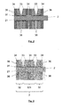
- Fig. 2 shows an enlarged section of Fig. 1 in the region of the connection between a rotor bar 2 and the first metal discs 33 of a short-circuit ring.
- a bonded connection 36 in the region of the recesses 31.
- the connection 36 can be a solder material which fills a solder gap.
- the connection 36 may be formed by molten material of the interconnected partners or by a welding filler material.
- Fig. 3 shows an enlarged section of another embodiment of a squirrel cage rotor 1 according to the invention in the region of the connection between a rotor bar 2 and a short-circuit ring 3.
- the short-circuit ring 3 consists of two mutually mirror-inverted arranged metal composite discs 32, each of a first 33 and a second 34 metal disc exist, and a metal composite disk 321 positioned therebetween, which consists of two first 33 and a second metal disc 34 arranged between them.
- a cohesive connection 36 in Area of the recesses 31.
- metal composite disks 32 which consist of more than two metal disks 33, 34, more complex than the production of pure bimetallic disks, however, the installation costs for the short-circuit ring 3 is significantly reduced by the use of such multilayer metal composite disks 321 .
- the embodiment according to Fig. 3 may be modified such that more than one metal composite disk 321 consisting of two first 33 and a second 34 metal disk disposed therebetween is used.
Landscapes
- Engineering & Computer Science (AREA)
- Power Engineering (AREA)
- Induction Machinery (AREA)
Applications Claiming Priority (1)
| Application Number | Priority Date | Filing Date | Title |
|---|---|---|---|
| DE102014013684.1A DE102014013684A1 (de) | 2014-09-17 | 2014-09-17 | Kurzschlussläufer |
Publications (3)
| Publication Number | Publication Date |
|---|---|
| EP2999101A2 true EP2999101A2 (fr) | 2016-03-23 |
| EP2999101A3 EP2999101A3 (fr) | 2016-04-06 |
| EP2999101B1 EP2999101B1 (fr) | 2017-12-06 |
Family
ID=54007449
Family Applications (1)
| Application Number | Title | Priority Date | Filing Date |
|---|---|---|---|
| EP15002495.8A Active EP2999101B1 (fr) | 2014-09-17 | 2015-08-22 | Rotor en court-circuit |
Country Status (5)
| Country | Link |
|---|---|
| US (2) | US20160079837A1 (fr) |
| EP (1) | EP2999101B1 (fr) |
| JP (1) | JP6624671B2 (fr) |
| DE (1) | DE102014013684A1 (fr) |
| HU (1) | HUE036087T2 (fr) |
Cited By (2)
| Publication number | Priority date | Publication date | Assignee | Title |
|---|---|---|---|---|
| EP3301795A1 (fr) * | 2016-09-30 | 2018-04-04 | Wieland-Werke AG | Procédé de fabrication d'une bague de court-circuit |
| EP3534512A1 (fr) * | 2018-02-28 | 2019-09-04 | Wieland-Werke AG | Rotor en court-circuit et procédé de fabrication d'un rotor en court-circuit |
Families Citing this family (8)
| Publication number | Priority date | Publication date | Assignee | Title |
|---|---|---|---|---|
| DE102013005050A1 (de) * | 2013-03-22 | 2014-09-25 | Wieland-Werke Ag | Kurzschlussläufer und dessen Einzelteile sowie Verfahren zur Herstellung eines Kurzschlussläufers |
| DE102014013684A1 (de) * | 2014-09-17 | 2016-03-17 | Wieland-Werke Ag | Kurzschlussläufer |
| DE102016204782A1 (de) * | 2016-03-23 | 2017-09-28 | Bayerische Motoren Werke Aktiengesellschaft | Rotor für Asynchronmaschine |
| CN206259769U (zh) * | 2016-10-27 | 2017-06-16 | 蔚来汽车有限公司 | 具有铜导条的电机转子结构 |
| DE102017206520A1 (de) | 2017-04-18 | 2018-10-18 | Audi Ag | Verfahren zur Herstellung eines Kurzschlussrotors und Kurzschlussrotor |
| DE102017010685A1 (de) * | 2017-11-16 | 2019-05-16 | Wieland-Werke Ag | Kurzschlussläufer und Verfahren zur Herstellung eines Kurzschlussläufers |
| DE102018008347A1 (de) * | 2018-10-23 | 2020-04-23 | Wieland-Werke Ag | Kurzschlussläufer |
| FR3131990A1 (fr) * | 2022-01-19 | 2023-07-21 | Safran Ventilation Systems | Rotor de machine électrique tournante comprenant des conducteurs de section libre |
Citations (3)
| Publication number | Priority date | Publication date | Assignee | Title |
|---|---|---|---|---|
| DE3421537A1 (de) | 1984-06-08 | 1985-12-12 | Siemens AG, 1000 Berlin und 8000 München | Kurzschlusslaeufer |
| DE19542962C1 (de) | 1995-11-17 | 1996-11-28 | Siemens Ag | Kurzschlußläufer für eine Asynchronmaschine und ein Verfahren zur Herstellung desselben |
| DE69734839T2 (de) | 1996-05-30 | 2006-06-29 | Rotatek Finland Oy | Läufer für eine elektrische maschine und verfahren zur erregung eines rotors in einer elektrischen maschine |
Family Cites Families (28)
| Publication number | Priority date | Publication date | Assignee | Title |
|---|---|---|---|---|
| US1371233A (en) * | 1918-08-21 | 1921-03-15 | Fries Joens Eleas | Rotor for squirrel-cage induction-motors and method of securing the winding thereto |
| US1694061A (en) * | 1926-08-13 | 1928-12-04 | Klaus L Hansen | Self-starting induction motor |
| US1936244A (en) * | 1927-02-11 | 1933-11-21 | B F Sturtevant Co | Laminated core member and method of making the same |
| US2499390A (en) * | 1944-07-10 | 1950-03-07 | Master Electric Co | Rotor for alternating current machines |
| US2421860A (en) * | 1945-05-02 | 1947-06-10 | Martin P Winther | Squirrel-cage rotor for induction machines |
| US2654848A (en) * | 1949-12-08 | 1953-10-06 | Schaefer Edward John | Submergible motor construction |
| US3694906A (en) * | 1971-10-14 | 1972-10-03 | Gen Motors Corp | Method for manufacturing a high speed squirrel cage rotor |
| JPS5484633A (en) | 1977-12-17 | 1979-07-05 | Mitsubishi Electric Corp | Combustor for liquid fuel |
| JPS57133245U (fr) * | 1981-02-12 | 1982-08-19 | ||
| JPS5854845A (ja) * | 1981-09-28 | 1983-03-31 | Mitsubishi Electric Corp | 回転電機の回転子 |
| JP2945228B2 (ja) * | 1993-02-18 | 1999-09-06 | ファナック株式会社 | 高速誘導電動機の籠形回転子の製造方法 |
| JP3083446B2 (ja) * | 1994-04-14 | 2000-09-04 | 株式会社デンソー | 高周波モータの回転子 |
| JP2670986B2 (ja) * | 1995-02-09 | 1997-10-29 | 明 千葉 | 電磁回転機械 |
| JPH09266647A (ja) * | 1996-03-27 | 1997-10-07 | Toyota Autom Loom Works Ltd | モータのロータ構造 |
| JP4157379B2 (ja) * | 2000-12-27 | 2008-10-01 | 株式会社日立製作所 | 回転電機 |
| US20050134137A1 (en) * | 2003-12-17 | 2005-06-23 | Sweo Edwin A. | Method for manufacturing squirrel cage rotor |
| US20070075603A1 (en) * | 2005-09-30 | 2007-04-05 | Whiddon Richard M | Labyrinthine end disk rotor |
| US20100231064A1 (en) * | 2009-03-11 | 2010-09-16 | Gm Global Technology Operations, Inc. | Balance ring for a vehicular electric machine |
| JP4728419B2 (ja) * | 2009-10-07 | 2011-07-20 | ファナック株式会社 | かご型ロータおよびかご型ロータの製造方法 |
| US8587178B2 (en) * | 2010-07-22 | 2013-11-19 | Gem Co., Ltd. | Rotor of high speed induction motor and manufacturing method thereof |
| WO2012011637A1 (fr) * | 2010-07-22 | 2012-01-26 | (주)지이엠 | Procédé de fabrication d'un rotor pour moteur à induction à grande vitesse, et rotor fabriqué à l'aide de celui-ci |
| JP5080664B2 (ja) * | 2011-02-24 | 2012-11-21 | ファナック株式会社 | 誘導電動機のかご型ロータ |
| WO2012137235A1 (fr) * | 2011-04-01 | 2012-10-11 | 三菱電機株式会社 | Rotor pour moteur à induction et procédé de fabrication d'un rotor pour moteur à induction |
| US9350217B2 (en) * | 2011-11-18 | 2016-05-24 | GM Global Technology Operations LLC | Rotor and method of forming same |
| DE102013005050A1 (de) * | 2013-03-22 | 2014-09-25 | Wieland-Werke Ag | Kurzschlussläufer und dessen Einzelteile sowie Verfahren zur Herstellung eines Kurzschlussläufers |
| DE102014013684A1 (de) * | 2014-09-17 | 2016-03-17 | Wieland-Werke Ag | Kurzschlussläufer |
| US9621012B2 (en) * | 2015-01-07 | 2017-04-11 | GM Global Technology Operations LLC | Lamination pack for skewed conductor bars and method of forming same |
| CN107819366A (zh) * | 2016-09-14 | 2018-03-20 | 上海蔚兰动力科技有限公司 | 感应电动机的转子及其制造方法 |
-
2014
- 2014-09-17 DE DE102014013684.1A patent/DE102014013684A1/de not_active Withdrawn
-
2015
- 2015-08-18 US US14/828,694 patent/US20160079837A1/en not_active Abandoned
- 2015-08-22 EP EP15002495.8A patent/EP2999101B1/fr active Active
- 2015-08-22 HU HUE15002495A patent/HUE036087T2/hu unknown
- 2015-08-28 JP JP2015168678A patent/JP6624671B2/ja active Active
-
2018
- 2018-08-07 US US16/056,678 patent/US10951102B2/en active Active
Patent Citations (3)
| Publication number | Priority date | Publication date | Assignee | Title |
|---|---|---|---|---|
| DE3421537A1 (de) | 1984-06-08 | 1985-12-12 | Siemens AG, 1000 Berlin und 8000 München | Kurzschlusslaeufer |
| DE19542962C1 (de) | 1995-11-17 | 1996-11-28 | Siemens Ag | Kurzschlußläufer für eine Asynchronmaschine und ein Verfahren zur Herstellung desselben |
| DE69734839T2 (de) | 1996-05-30 | 2006-06-29 | Rotatek Finland Oy | Läufer für eine elektrische maschine und verfahren zur erregung eines rotors in einer elektrischen maschine |
Cited By (2)
| Publication number | Priority date | Publication date | Assignee | Title |
|---|---|---|---|---|
| EP3301795A1 (fr) * | 2016-09-30 | 2018-04-04 | Wieland-Werke AG | Procédé de fabrication d'une bague de court-circuit |
| EP3534512A1 (fr) * | 2018-02-28 | 2019-09-04 | Wieland-Werke AG | Rotor en court-circuit et procédé de fabrication d'un rotor en court-circuit |
Also Published As
| Publication number | Publication date |
|---|---|
| US10951102B2 (en) | 2021-03-16 |
| EP2999101B1 (fr) | 2017-12-06 |
| EP2999101A3 (fr) | 2016-04-06 |
| US20180342935A1 (en) | 2018-11-29 |
| JP2016063740A (ja) | 2016-04-25 |
| DE102014013684A1 (de) | 2016-03-17 |
| JP6624671B2 (ja) | 2019-12-25 |
| US20160079837A1 (en) | 2016-03-17 |
| HUE036087T2 (hu) | 2018-06-28 |
Similar Documents
| Publication | Publication Date | Title |
|---|---|---|
| EP2999101B1 (fr) | Rotor en court-circuit | |
| EP2782222B1 (fr) | Rotor en court-circuit et procédé de fabrication d'un rotor en court-circuit | |
| EP3487048A1 (fr) | Rotor à cage écureuil comprenant des anneaux de court-circuit divisés et procédé de fabrication d'un tel rotor à cage écureuil | |
| DE102010047816A1 (de) | Käfigrotor und Herstellungsverfahren für einen Käfigrotor | |
| WO2017089034A1 (fr) | Rotor à cage et procédé de réalisation | |
| EP3574574B1 (fr) | Procédé de fabrication d'un rotor à cage d'écureuil d'une machine asynchrone | |
| EP3741031B1 (fr) | Procédé de fabrication d'un rotor à cage d'écureuil | |
| DE102012003195A1 (de) | Kurzschlussläufer für einen Induktionsmotor | |
| WO2014198477A2 (fr) | Anneau de court-circuit pour machine électrique asynchrone composé de segments en portions d'arc de cercle | |
| DE102011080468B4 (de) | Verfahren zur Herstellung eines Kontaktträgers eines Schaltkontaktes für ein elektromechanisches Schaltgerät sowie ein solcher Kontaktträger | |
| EP2957026B1 (fr) | Cage en court-circuit pour moteur à rotor en court-circuit et procédé de production correspondant | |
| EP3393016B1 (fr) | Procédé de fabrication d'un rotor à court-circuit et rotor à court-circuit | |
| EP3534512B1 (fr) | Rotor en court-circuit et procédé de fabrication d'un rotor en court-circuit | |
| EP2957025B1 (fr) | Cage en court-circuit pour rotor en court-circuit et procédé de réalisation | |
| EP3518398A1 (fr) | Bague terminale courte pour raccordement avec les barres de cage | |
| EP3493371A1 (fr) | Rotor en cage d'écureuil renforcé | |
| EP3301795A1 (fr) | Procédé de fabrication d'une bague de court-circuit | |
| DE19626807C1 (de) | Rotor für einen Asynchronmotor, Verfahren zur Herstellung des Rotors, und Asynchronmotor | |
| EP4324574A1 (fr) | Palier lisse multicouche et procédé de fabrication d'un palier lisse multicouche | |
| EP4436015A1 (fr) | Rotor d'un moteur à cage d'écureuil, moteur à cage d'écureuil comprenant un rotor et procédé de fabrication d'un rotor d'un moteur à cage d'écureuil | |
| EP4277096A1 (fr) | Rotor d'un moteur à rotor à cage d'écureuil et son procédé de fabrication | |
| EP0998015A2 (fr) | Méthode de production d'un rotor pour moteur asynchrone et rotor fabriqué selon ladite méthode | |
| WO2019192665A1 (fr) | Bague de court-circuit et rotor en court-circuit pour machine asynchrone | |
| EP4568080A1 (fr) | Cage de rotor en court-circuit, ensemble rotor et procédé d'assemblage | |
| DE102019123552A1 (de) | Verfahren zur Herstellung eines Rotors, Rotor sowie Asynchronmotor |
Legal Events
| Date | Code | Title | Description |
|---|---|---|---|
| PUAL | Search report despatched |
Free format text: ORIGINAL CODE: 0009013 |
|
| PUAI | Public reference made under article 153(3) epc to a published international application that has entered the european phase |
Free format text: ORIGINAL CODE: 0009012 |
|
| AK | Designated contracting states |
Kind code of ref document: A2 Designated state(s): AL AT BE BG CH CY CZ DE DK EE ES FI FR GB GR HR HU IE IS IT LI LT LU LV MC MK MT NL NO PL PT RO RS SE SI SK SM TR |
|
| AX | Request for extension of the european patent |
Extension state: BA ME |
|
| AK | Designated contracting states |
Kind code of ref document: A3 Designated state(s): AL AT BE BG CH CY CZ DE DK EE ES FI FR GB GR HR HU IE IS IT LI LT LU LV MC MK MT NL NO PL PT RO RS SE SI SK SM TR |
|
| AX | Request for extension of the european patent |
Extension state: BA ME |
|
| RIC1 | Information provided on ipc code assigned before grant |
Ipc: H02K 17/16 20060101AFI20160226BHEP Ipc: H02K 15/00 20060101ALI20160226BHEP |
|
| 17P | Request for examination filed |
Effective date: 20160519 |
|
| RBV | Designated contracting states (corrected) |
Designated state(s): AL AT BE BG CH CY CZ DE DK EE ES FI FR GB GR HR HU IE IS IT LI LT LU LV MC MK MT NL NO PL PT RO RS SE SI SK SM TR |
|
| 17Q | First examination report despatched |
Effective date: 20161221 |
|
| GRAP | Despatch of communication of intention to grant a patent |
Free format text: ORIGINAL CODE: EPIDOSNIGR1 |
|
| INTG | Intention to grant announced |
Effective date: 20170718 |
|
| GRAS | Grant fee paid |
Free format text: ORIGINAL CODE: EPIDOSNIGR3 |
|
| GRAA | (expected) grant |
Free format text: ORIGINAL CODE: 0009210 |
|
| AK | Designated contracting states |
Kind code of ref document: B1 Designated state(s): AL AT BE BG CH CY CZ DE DK EE ES FI FR GB GR HR HU IE IS IT LI LT LU LV MC MK MT NL NO PL PT RO RS SE SI SK SM TR |
|
| REG | Reference to a national code |
Ref country code: GB Ref legal event code: FG4D Free format text: NOT ENGLISH |
|
| REG | Reference to a national code |
Ref country code: AT Ref legal event code: REF Ref document number: 953223 Country of ref document: AT Kind code of ref document: T Effective date: 20171215 Ref country code: CH Ref legal event code: EP |
|
| REG | Reference to a national code |
Ref country code: IE Ref legal event code: FG4D Free format text: LANGUAGE OF EP DOCUMENT: GERMAN |
|
| REG | Reference to a national code |
Ref country code: DE Ref legal event code: R096 Ref document number: 502015002462 Country of ref document: DE |
|
| REG | Reference to a national code |
Ref country code: SE Ref legal event code: TRGR |
|
| REG | Reference to a national code |
Ref country code: NL Ref legal event code: MP Effective date: 20171206 |
|
| REG | Reference to a national code |
Ref country code: LT Ref legal event code: MG4D |
|
| PG25 | Lapsed in a contracting state [announced via postgrant information from national office to epo] |
Ref country code: FI Free format text: LAPSE BECAUSE OF FAILURE TO SUBMIT A TRANSLATION OF THE DESCRIPTION OR TO PAY THE FEE WITHIN THE PRESCRIBED TIME-LIMIT Effective date: 20171206 Ref country code: NO Free format text: LAPSE BECAUSE OF FAILURE TO SUBMIT A TRANSLATION OF THE DESCRIPTION OR TO PAY THE FEE WITHIN THE PRESCRIBED TIME-LIMIT Effective date: 20180306 Ref country code: LT Free format text: LAPSE BECAUSE OF FAILURE TO SUBMIT A TRANSLATION OF THE DESCRIPTION OR TO PAY THE FEE WITHIN THE PRESCRIBED TIME-LIMIT Effective date: 20171206 Ref country code: ES Free format text: LAPSE BECAUSE OF FAILURE TO SUBMIT A TRANSLATION OF THE DESCRIPTION OR TO PAY THE FEE WITHIN THE PRESCRIBED TIME-LIMIT Effective date: 20171206 |
|
| PG25 | Lapsed in a contracting state [announced via postgrant information from national office to epo] |
Ref country code: HR Free format text: LAPSE BECAUSE OF FAILURE TO SUBMIT A TRANSLATION OF THE DESCRIPTION OR TO PAY THE FEE WITHIN THE PRESCRIBED TIME-LIMIT Effective date: 20171206 Ref country code: GR Free format text: LAPSE BECAUSE OF FAILURE TO SUBMIT A TRANSLATION OF THE DESCRIPTION OR TO PAY THE FEE WITHIN THE PRESCRIBED TIME-LIMIT Effective date: 20180307 Ref country code: LV Free format text: LAPSE BECAUSE OF FAILURE TO SUBMIT A TRANSLATION OF THE DESCRIPTION OR TO PAY THE FEE WITHIN THE PRESCRIBED TIME-LIMIT Effective date: 20171206 Ref country code: BG Free format text: LAPSE BECAUSE OF FAILURE TO SUBMIT A TRANSLATION OF THE DESCRIPTION OR TO PAY THE FEE WITHIN THE PRESCRIBED TIME-LIMIT Effective date: 20180306 Ref country code: RS Free format text: LAPSE BECAUSE OF FAILURE TO SUBMIT A TRANSLATION OF THE DESCRIPTION OR TO PAY THE FEE WITHIN THE PRESCRIBED TIME-LIMIT Effective date: 20171206 |
|
| REG | Reference to a national code |
Ref country code: HU Ref legal event code: AG4A Ref document number: E036087 Country of ref document: HU |
|
| PG25 | Lapsed in a contracting state [announced via postgrant information from national office to epo] |
Ref country code: NL Free format text: LAPSE BECAUSE OF FAILURE TO SUBMIT A TRANSLATION OF THE DESCRIPTION OR TO PAY THE FEE WITHIN THE PRESCRIBED TIME-LIMIT Effective date: 20171206 |
|
| REG | Reference to a national code |
Ref country code: FR Ref legal event code: PLFP Year of fee payment: 4 |
|
| PG25 | Lapsed in a contracting state [announced via postgrant information from national office to epo] |
Ref country code: CZ Free format text: LAPSE BECAUSE OF FAILURE TO SUBMIT A TRANSLATION OF THE DESCRIPTION OR TO PAY THE FEE WITHIN THE PRESCRIBED TIME-LIMIT Effective date: 20171206 Ref country code: EE Free format text: LAPSE BECAUSE OF FAILURE TO SUBMIT A TRANSLATION OF THE DESCRIPTION OR TO PAY THE FEE WITHIN THE PRESCRIBED TIME-LIMIT Effective date: 20171206 Ref country code: SK Free format text: LAPSE BECAUSE OF FAILURE TO SUBMIT A TRANSLATION OF THE DESCRIPTION OR TO PAY THE FEE WITHIN THE PRESCRIBED TIME-LIMIT Effective date: 20171206 |
|
| PG25 | Lapsed in a contracting state [announced via postgrant information from national office to epo] |
Ref country code: RO Free format text: LAPSE BECAUSE OF FAILURE TO SUBMIT A TRANSLATION OF THE DESCRIPTION OR TO PAY THE FEE WITHIN THE PRESCRIBED TIME-LIMIT Effective date: 20171206 Ref country code: PL Free format text: LAPSE BECAUSE OF FAILURE TO SUBMIT A TRANSLATION OF THE DESCRIPTION OR TO PAY THE FEE WITHIN THE PRESCRIBED TIME-LIMIT Effective date: 20171206 Ref country code: SM Free format text: LAPSE BECAUSE OF FAILURE TO SUBMIT A TRANSLATION OF THE DESCRIPTION OR TO PAY THE FEE WITHIN THE PRESCRIBED TIME-LIMIT Effective date: 20171206 |
|
| REG | Reference to a national code |
Ref country code: DE Ref legal event code: R097 Ref document number: 502015002462 Country of ref document: DE |
|
| PG25 | Lapsed in a contracting state [announced via postgrant information from national office to epo] |
Ref country code: MT Free format text: LAPSE BECAUSE OF FAILURE TO SUBMIT A TRANSLATION OF THE DESCRIPTION OR TO PAY THE FEE WITHIN THE PRESCRIBED TIME-LIMIT Effective date: 20171206 |
|
| PLBE | No opposition filed within time limit |
Free format text: ORIGINAL CODE: 0009261 |
|
| STAA | Information on the status of an ep patent application or granted ep patent |
Free format text: STATUS: NO OPPOSITION FILED WITHIN TIME LIMIT |
|
| 26N | No opposition filed |
Effective date: 20180907 |
|
| PG25 | Lapsed in a contracting state [announced via postgrant information from national office to epo] |
Ref country code: SI Free format text: LAPSE BECAUSE OF FAILURE TO SUBMIT A TRANSLATION OF THE DESCRIPTION OR TO PAY THE FEE WITHIN THE PRESCRIBED TIME-LIMIT Effective date: 20171206 Ref country code: DK Free format text: LAPSE BECAUSE OF FAILURE TO SUBMIT A TRANSLATION OF THE DESCRIPTION OR TO PAY THE FEE WITHIN THE PRESCRIBED TIME-LIMIT Effective date: 20171206 |
|
| PG25 | Lapsed in a contracting state [announced via postgrant information from national office to epo] |
Ref country code: MC Free format text: LAPSE BECAUSE OF FAILURE TO SUBMIT A TRANSLATION OF THE DESCRIPTION OR TO PAY THE FEE WITHIN THE PRESCRIBED TIME-LIMIT Effective date: 20171206 |
|
| REG | Reference to a national code |
Ref country code: CH Ref legal event code: PL |
|
| PG25 | Lapsed in a contracting state [announced via postgrant information from national office to epo] |
Ref country code: CH Free format text: LAPSE BECAUSE OF NON-PAYMENT OF DUE FEES Effective date: 20180831 Ref country code: LI Free format text: LAPSE BECAUSE OF NON-PAYMENT OF DUE FEES Effective date: 20180831 Ref country code: LU Free format text: LAPSE BECAUSE OF NON-PAYMENT OF DUE FEES Effective date: 20180822 |
|
| REG | Reference to a national code |
Ref country code: BE Ref legal event code: MM Effective date: 20180831 |
|
| PG25 | Lapsed in a contracting state [announced via postgrant information from national office to epo] |
Ref country code: BE Free format text: LAPSE BECAUSE OF NON-PAYMENT OF DUE FEES Effective date: 20180831 |
|
| PG25 | Lapsed in a contracting state [announced via postgrant information from national office to epo] |
Ref country code: TR Free format text: LAPSE BECAUSE OF FAILURE TO SUBMIT A TRANSLATION OF THE DESCRIPTION OR TO PAY THE FEE WITHIN THE PRESCRIBED TIME-LIMIT Effective date: 20171206 |
|
| PG25 | Lapsed in a contracting state [announced via postgrant information from national office to epo] |
Ref country code: PT Free format text: LAPSE BECAUSE OF FAILURE TO SUBMIT A TRANSLATION OF THE DESCRIPTION OR TO PAY THE FEE WITHIN THE PRESCRIBED TIME-LIMIT Effective date: 20171206 |
|
| PG25 | Lapsed in a contracting state [announced via postgrant information from national office to epo] |
Ref country code: CY Free format text: LAPSE BECAUSE OF FAILURE TO SUBMIT A TRANSLATION OF THE DESCRIPTION OR TO PAY THE FEE WITHIN THE PRESCRIBED TIME-LIMIT Effective date: 20171206 Ref country code: IE Free format text: LAPSE BECAUSE OF NON-PAYMENT OF DUE FEES Effective date: 20180822 Ref country code: MK Free format text: LAPSE BECAUSE OF NON-PAYMENT OF DUE FEES Effective date: 20171206 |
|
| PG25 | Lapsed in a contracting state [announced via postgrant information from national office to epo] |
Ref country code: AL Free format text: LAPSE BECAUSE OF FAILURE TO SUBMIT A TRANSLATION OF THE DESCRIPTION OR TO PAY THE FEE WITHIN THE PRESCRIBED TIME-LIMIT Effective date: 20171206 Ref country code: IS Free format text: LAPSE BECAUSE OF FAILURE TO SUBMIT A TRANSLATION OF THE DESCRIPTION OR TO PAY THE FEE WITHIN THE PRESCRIBED TIME-LIMIT Effective date: 20180406 |
|
| PGFP | Annual fee paid to national office [announced via postgrant information from national office to epo] |
Ref country code: SE Payment date: 20250610 Year of fee payment: 11 |
|
| PGFP | Annual fee paid to national office [announced via postgrant information from national office to epo] |
Ref country code: HU Payment date: 20250728 Year of fee payment: 11 |
|
| PGFP | Annual fee paid to national office [announced via postgrant information from national office to epo] |
Ref country code: DE Payment date: 20250831 Year of fee payment: 11 |
|
| PGFP | Annual fee paid to national office [announced via postgrant information from national office to epo] |
Ref country code: IT Payment date: 20250722 Year of fee payment: 11 |
|
| PGFP | Annual fee paid to national office [announced via postgrant information from national office to epo] |
Ref country code: GB Payment date: 20250703 Year of fee payment: 11 |
|
| PGFP | Annual fee paid to national office [announced via postgrant information from national office to epo] |
Ref country code: FR Payment date: 20250703 Year of fee payment: 11 Ref country code: AT Payment date: 20250725 Year of fee payment: 11 |