EP3000589A1 - Appareil de moulage - Google Patents
Appareil de moulage Download PDFInfo
- Publication number
- EP3000589A1 EP3000589A1 EP15795095.7A EP15795095A EP3000589A1 EP 3000589 A1 EP3000589 A1 EP 3000589A1 EP 15795095 A EP15795095 A EP 15795095A EP 3000589 A1 EP3000589 A1 EP 3000589A1
- Authority
- EP
- European Patent Office
- Prior art keywords
- die
- divided
- gas
- cavity
- dies
- Prior art date
- Legal status (The legal status is an assumption and is not a legal conclusion. Google has not performed a legal analysis and makes no representation as to the accuracy of the status listed.)
- Granted
Links
Images

Classifications
-
- B—PERFORMING OPERATIONS; TRANSPORTING
- B22—CASTING; POWDER METALLURGY
- B22F—WORKING METALLIC POWDER; MANUFACTURE OF ARTICLES FROM METALLIC POWDER; MAKING METALLIC POWDER; APPARATUS OR DEVICES SPECIALLY ADAPTED FOR METALLIC POWDER
- B22F3/00—Manufacture of workpieces or articles from metallic powder characterised by the manner of compacting or sintering; Apparatus specially adapted therefor ; Presses and furnaces
- B22F3/02—Compacting only
- B22F3/03—Press-moulding apparatus therefor
-
- B—PERFORMING OPERATIONS; TRANSPORTING
- B30—PRESSES
- B30B—PRESSES IN GENERAL
- B30B15/00—Details of, or accessories for, presses; Auxiliary measures in connection with pressing
- B30B15/02—Dies; Inserts therefor; Mounting thereof; Moulds
- B30B15/022—Moulds for compacting material in powder, granular of pasta form
-
- B—PERFORMING OPERATIONS; TRANSPORTING
- B28—WORKING CEMENT, CLAY, OR STONE
- B28B—SHAPING CLAY OR OTHER CERAMIC COMPOSITIONS; SHAPING SLAG; SHAPING MIXTURES CONTAINING CEMENTITIOUS MATERIAL, e.g. PLASTER
- B28B7/00—Moulds; Cores; Mandrels
- B28B7/38—Treating surfaces of moulds, cores, or mandrels to prevent sticking
- B28B7/386—Cleaning
-
- B—PERFORMING OPERATIONS; TRANSPORTING
- B29—WORKING OF PLASTICS; WORKING OF SUBSTANCES IN A PLASTIC STATE IN GENERAL
- B29C—SHAPING OR JOINING OF PLASTICS; SHAPING OF MATERIAL IN A PLASTIC STATE, NOT OTHERWISE PROVIDED FOR; AFTER-TREATMENT OF THE SHAPED PRODUCTS, e.g. REPAIRING
- B29C43/00—Compression moulding, i.e. applying external pressure to flow the moulding material; Apparatus therefor
- B29C43/32—Component parts, details or accessories; Auxiliary operations
-
- B—PERFORMING OPERATIONS; TRANSPORTING
- B30—PRESSES
- B30B—PRESSES IN GENERAL
- B30B11/00—Presses specially adapted for forming shaped articles from material in particulate or plastic state, e.g. briquetting presses, tabletting presses
- B30B11/007—Presses specially adapted for forming shaped articles from material in particulate or plastic state, e.g. briquetting presses, tabletting presses using a plurality of pressing members working in different directions
-
- B—PERFORMING OPERATIONS; TRANSPORTING
- B30—PRESSES
- B30B—PRESSES IN GENERAL
- B30B15/00—Details of, or accessories for, presses; Auxiliary measures in connection with pressing
- B30B15/0082—Dust eliminating means; Mould or press ram cleaning means
-
- B—PERFORMING OPERATIONS; TRANSPORTING
- B29—WORKING OF PLASTICS; WORKING OF SUBSTANCES IN A PLASTIC STATE IN GENERAL
- B29C—SHAPING OR JOINING OF PLASTICS; SHAPING OF MATERIAL IN A PLASTIC STATE, NOT OTHERWISE PROVIDED FOR; AFTER-TREATMENT OF THE SHAPED PRODUCTS, e.g. REPAIRING
- B29C43/00—Compression moulding, i.e. applying external pressure to flow the moulding material; Apparatus therefor
- B29C43/32—Component parts, details or accessories; Auxiliary operations
- B29C2043/3205—Particular pressure exerting means for making definite articles
- B29C2043/3222—Particular pressure exerting means for making definite articles pressurized gas, e.g. air
- B29C2043/3233—Particular pressure exerting means for making definite articles pressurized gas, e.g. air exerting pressure on mould parts
Definitions
- the present invention relates to a die apparatus for use in powder compaction of metals, ceramics, or the like.
- an apparatus including a die having a cavity and upper and lower punches respectively inserted into the cavity from above and below of the cavity is used.
- the cavity of the die is filled with powder of metal, ceramics, or the like, and the powder is compacted by the punches inserted into the cavity from above and below of the die so as to compact the powder.
- the die may be divided into two or more.
- Each of the divided dies has cut surfaces extending along a moving direction of the punches, and is reciprocatingly movable in a direction of forming the cavity.
- each of the dies is moved forward in the direction of the cavity from three directions, and each die comes into contact with the adjacent dies on the cut surfaces thereof so as to close the dies, thereby forming the cavity (see Patent Literature 1, for example).
- Patent Literature 1 Japanese Patent Laid-Open No. H10-94899
- the aforementioned conventional die apparatus has the following inconvenience: when the dies are moved backward after forming the powder compact, some powder drops from the powder supply apparatus, or the powder intrudes into a gap between the cut surfaces in contact with each other if the dies have abrasion, so that the powder adheres to the cut surfaces in some cases. Powder adhering to the cut surfaces hinders tight contact between the cut surfaces when the dies are moved forward to produce a next powder compact, which makes it difficult to form a cavity having a desired shape in some cases.
- An object of the present invention is to provide a die apparatus capable of solving the aforementioned inoonvenience, by removing powder adhering to cut surfaces so as to securely form a cavity having a desired shape.
- the present invention is directed to a die apparatus including: a plurality of divided dies configured to come into contact with one another on cut surfaces thereof so as to form a cavity; a plurality of sliders configured to reciprocatingly drive each of the plurality of divided dies; and an upper punch and a lower punch that are inserted into the cavity from above and below of the cavity.
- At least one divided die is provided with a gas passage configured to inject gas through a gas injection port disposed in each cut surface.
- the gas is injected from the gas injection port through the gas passage formed in at least one of the divided dies of the pair of divided dies, thereby generating an air flow in a gap between the pair of divided dies.
- the flow rate of the air flow increases as the gap between the pair of divided dies becomes narrow, and thus the powder adhering to the cut surfaces of the pair of divided dies that oppose each other can be blown off and removed.
- it is possible to bring the cut surfaces of the pair of divided dies into contact with each other with no powder in the gap between the pair of divided dies, thus securely forming the cavity having a desired shape.
- the gas passage of the one divided die and the gas passage of the other divided die are configured such that a position of the gas injection port in each cut surface of the one divided die deviates from a position of the gas injection port in each cut surface of the other divided die.
- the above configured die apparatus it is possible to prevent the gas injected from each of the gas injection ports of the one divided die and the other divided die from colliding and interfering with each other.
- the gas injected from each of the gas injection ports of the one divided die and the other divided die can separately generate an air flow in the gap between the two divided dies, thereby efficiently removing the powder present in the gap.
- a groove is formed in each cut surface of the at least one divided die in such a manner that the groove is continued to the gas injection port, and at least a part of the groove extends in a vertical direction.
- the air flow can be readily guided in a wide range in the vertical direction in the gap between the pair of divided dies whose cut surfaces closely oppose each other, thus efficiently removing the powder present in the gap.
- At least one slider of the plurality of sliders is provided with an auxiliary gas passage that is connected to a gas supply apparatus through a gas introduction port and also communicate with the gas passage of the at least one divided die.
- the gas supplied from the gas supply apparatus through the gas introduction port into the auxiliary gas passages formed in the slider is guided from the air injection port through the air passage formed in the divided die communicating with the auxiliary gas passage, into the gap between the divided die and the other divided die that closely oppose each other.
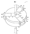
- a die apparatus 1 as one embodiment of the present invention includes a die base 2 formed of a donut-shaped disk having a through-hole 17 (see FIG. 2 and FIG. 3 ) at a center thereof, and three divided dies 4a, 4b, 4c that come into contact with one another to form a cavity 3.
- the die base 2 includes guide grooves 5a, 5b, 5c radially extending from the through-hole 17 with equal intervals, and the divided dies 4a, 4b, 4c are driven by respective sliders 6a, 6b, 6c coupled to corresponding rear ends (on an opposite side to the cavity 3) of the divided dies 4a, 4b, 4c so as to be reciprocatingly movable along the guide grooves 5a, 5b, 5c.
- Each divided die 4i is moved forward by each slider 6i so that the divided die 4i and the other divided dies 4i+ and 4i- mutually come into contact with one another on respective cut surfaces 11a, 11b of the divided die 4i, thereby forming the cavity 3 by the divided dies 4a, 4b, 4c at the through-hole 17 located at the center of the die base 2.
- the die apparatus 1 is provided with an upper punch 7a inserted into the cavity 3 from above of the cavity 3, a lower punch 7b inserted into the cavity 3 from below of the cavity 3, and a powder supply apparatus (not shown) to supply powder of metal, ceramics, or the like into the cavity 3.
- the cavity 3 is formed by the divided die 4i driven by the slider 6i, and the lower punch 7b is inserted into the cavity 3. Subsequently, in this state, powder supplied from the powder supply apparatus is filled into the cavity 3, and the powder filled in the cavity 3 is compacted by the upper punch 7a and the lower punch 7b so as to produce a powder compact.
- the divided die 4i is driven backward by the slider 6i as to open the dies, the upper punch 7a is detached from the cavity 3, and the powder compact is knocked out to be ejected by the lower punch 7b.
- the powder filled in the cavity 3 is compacted by the upper punch 7a and the lower punch 7b, and if at least one of the cut surfaces 11a and 11b of the divided die 4i has a gap due to abrasion, the powder might intrude into the gap, and adhere to the cut surfaces. Also, when the dies are opened (when each divided die 4i is driven backward), the powder supplied from the powder supply apparatus may drop and adhere to the cut surfaces. If the powder remains adhered to the cut surfaces, the divided dies 4a, 4b, 4c cannot come into contact with one another on the cut surfaces thereof, thus hindering formation of the cavity in a desired shape in some cases.
- the cut surfaces 11a, 11b to come into contact with the other pair of divided dies 4b and 4c are formed at a front end of the divided die 4a.
- a representation "j" is appropriately used.
- Each cut surface 11j extends in a moving direction of the upper punch 7a and the lower punch 7b, that is, in the vertical direction.
- a gas passage 16j is formed in the divided die 4a in a manner as to inject gas (gas or air) from the cut surface 11j through a gas injection port 12j.
- a recess 13 that is recessed backward is formed between the cut surfaces 11a and 11b of the divided die 4a.
- the gas injection port 12a is located at an upper position from the center of the cut surface 11a on one side, and the gas injection port 12b is located at a lower position from the center of the cut surface 11b on the other side.
- a groove 14j to guide the gas injected from the gas injection port 12j in the vertical direction of each cut surface 11j is formed in each cut surface 11j.
- the gas injection port 12j opens in a manner as to be continued to the groove 14j (a bottom, for example).
- auxiliary gas passages 18j are formed forwardly extending auxiliary gas passages 18j continued from corresponding gas introduction ports 15j located at a rear position in the slider 6a.
- Each auxiliary gas passage 18j is configured to communicate with the corresponding gas passage 16j formed in the divided die 4a in a state in which the front end of the slider 6a and the rear end of the divided die 4a are in contact with each other.
- the gas supplied from a gas supply apparatus connected to each gas introduction port 15j via a conduit or the like is injected from each gas injection port 12j through each auxiliary gas passage 18j and each gas passage 16j.
- An example of the gas may include an inert gas, such as carbon dioxide and nitrogen, or compressed air.
- An example of the gas supply apparatus may include a carbon dioxide cylinder, a nitrogen cylinder, or the like if the gas is an inert gas; and a compressed air cylinder, an air compressor, or the like if the gas is compressed air.
- the other sets between the divided die 4b and the slider 6b, and between the divided die 4c and the slider 6c have the same configurations as that of the divided die 4a and the slider 6a.
- each divided die 4i are driven forward by each slider 6i.
- the gas is injected from the cut surface 11b of the divided die 4a through the gas injection port 12b, and the gas is also injected from the cut surface 11a of the divided die 4c through the gas injection port 12a.
- Each injection port 12j has a diameter within a range of 0.2 to 1.0 [mm], for example.
- As the gas for example, compressed air at a pressure of 0.5 to 1.0 [MPa] produced in facility of a plant is used after being subjected to flow regulation with a throttle valve.
- the gas After being injected from each of the gas injection ports 12a and 12b, the gas generates an air flow flowing along each of one cut surface 11a and the other cut surface 11b that oppose each other.
- the gas injection port 12a In one divided die 4a, the gas injection port 12a is located at an upper position of the cut surface 11a, and in the other divided die 4c, the gas injection port 12b is located at a lower position of the cut surface 11b; thus there is a difference in height therebetween. Accordingly, the gas injected from each of the gas injection ports 12a and 12b can separately generate an air flow without colliding and interfering with each other.
- the gas is guided by the respective grooves 14a and 14b in the vertical direction, thus generating the air flow spreading in a wide range in the vertical direction in the gap between the cut surfaces 11a and 11b that oppose each other.
- the gap between the cut surfaces 11 a and 11b becomes decreased, so that a flow rate of the air flow is increased, thus blowing off and removing the powder adhering to the cut surfaces 11a and 11b.
- Decrease in gap between the cut surfaces 11a and is 11b that oppose each other allows the grooves 14a and 14b to more effectively exert their effects, thus readily blowing off and removing the powder.
- only one of the cut surfaces 11a and 11b in pair may be provided with the gas injection port 12a or the gas injection port 12b.
- the gas passage 16a or 16b formed in the divided die 4i may be modified to extend in various manners.
- the gas passage 16a or the gas passage 16b may be formed in a manner as to be connected to (not a singularity of, but) a plurality of gas injection ports 12a or gas injection ports 12b.
- the gas passage 16a or 16b may be formed to obliquely (not in parallel) extend relative to an axial direction of each divided die 4i in a top view or in a side view.
- the gas injection port 12a and the gas injection port 12b respectively formed in the cut surface 11a and the cut surface 11b that oppose each other may be arranged at the same height According to this configuration, it is possible to cause the gas injected from the gas injection port 12a and the gas injected from the gas injection port 12b toward the gap between one divided die 4i and the other divided die 4i- (or 4i+) to interfere with each other.
- the cavity 3 is formed by the three divided dies 4a to 4c, but as another embodiment, the cavity may be formed by a plurality of divided dies, specifically, two divided dies, or four or more divided dies.
Landscapes
- Engineering & Computer Science (AREA)
- Mechanical Engineering (AREA)
- Manufacturing & Machinery (AREA)
- Chemical & Material Sciences (AREA)
- Ceramic Engineering (AREA)
- Powder Metallurgy (AREA)
- Mounting, Exchange, And Manufacturing Of Dies (AREA)
- Moulds For Moulding Plastics Or The Like (AREA)
Applications Claiming Priority (2)
| Application Number | Priority Date | Filing Date | Title |
|---|---|---|---|
| JP2015007257A JP5821111B1 (ja) | 2015-01-16 | 2015-01-16 | 金型装置 |
| PCT/JP2015/068202 WO2015194681A1 (fr) | 2015-01-16 | 2015-06-24 | Appareil de moulage |
Publications (3)
| Publication Number | Publication Date |
|---|---|
| EP3000589A1 true EP3000589A1 (fr) | 2016-03-30 |
| EP3000589A4 EP3000589A4 (fr) | 2017-05-24 |
| EP3000589B1 EP3000589B1 (fr) | 2018-06-27 |
Family
ID=54610968
Family Applications (1)
| Application Number | Title | Priority Date | Filing Date |
|---|---|---|---|
| EP15795095.7A Active EP3000589B1 (fr) | 2015-01-16 | 2015-06-24 | Appareil de moulage |
Country Status (7)
| Country | Link |
|---|---|
| US (1) | US10046391B2 (fr) |
| EP (1) | EP3000589B1 (fr) |
| JP (1) | JP5821111B1 (fr) |
| KR (1) | KR101736028B1 (fr) |
| CN (1) | CN105992690B (fr) |
| TW (1) | TWI650194B (fr) |
| WO (1) | WO2015194681A1 (fr) |
Families Citing this family (2)
| Publication number | Priority date | Publication date | Assignee | Title |
|---|---|---|---|---|
| CN110576630B (zh) * | 2018-06-07 | 2022-04-12 | 宁波杉越新材料有限公司 | 材料压缩装置 |
| WO2020027101A1 (fr) * | 2018-07-31 | 2020-02-06 | 小林工業株式会社 | Appareil de moulage de poudre, matrice de moulage de poudre et procédé de préparation de corps moulé en poudre |
Family Cites Families (14)
| Publication number | Priority date | Publication date | Assignee | Title |
|---|---|---|---|---|
| US5093076A (en) * | 1991-05-15 | 1992-03-03 | General Motors Corporation | Hot pressed magnets in open air presses |
| DE59506072D1 (de) * | 1994-04-27 | 1999-07-08 | Dorst Masch & Anlagen | Verfahren zur Herstellung von Presslingen aus pulverförmigem Material sowie entsprechende Presse |
| DE4428842C1 (de) * | 1994-08-02 | 1996-01-18 | Mannesmann Ag | Vorrichtung zur Herstellung von Preßkörpern |
| SE9502587D0 (sv) * | 1995-07-11 | 1995-07-11 | Attexor Equip | A tool for making joints between sheet-formed members |
| JPH1094899A (ja) | 1996-09-26 | 1998-04-14 | Mitsubishi Materials Corp | スローアウェイチップの製造方法及び装置 |
| JP3433683B2 (ja) * | 1998-10-28 | 2003-08-04 | トヨタ自動車株式会社 | 粉末成形型及び粉末の成形方法 |
| SE0001522L (sv) * | 2000-04-27 | 2001-10-28 | Skf Nova Ab | Förfarande och anordning för att kompaktera ett pulvermaterial till en homogen artikel |
| CN1597191A (zh) * | 2003-09-19 | 2005-03-23 | 东炭化工株式会社 | 粉粒体的成形装置、成形方法、该方法所获得的成形体 |
| JP2006187775A (ja) | 2004-12-28 | 2006-07-20 | Tdk Corp | 粉末成形装置及び粉末成形方法 |
| AT505947B1 (de) * | 2007-11-14 | 2016-04-15 | Miba Sinter Austria Gmbh | Verdichtungswerkzeug |
| US8033805B2 (en) * | 2007-11-27 | 2011-10-11 | Kennametal Inc. | Method and apparatus for cross-passageway pressing to produce cutting inserts |
| IL214642A (en) * | 2011-08-14 | 2015-07-30 | Iscar Ltd | Cutting die system |
| CN203030704U (zh) * | 2012-12-28 | 2013-07-03 | 天津市特富龙金属制品有限公司 | 冲压模具 |
| AT14230U1 (de) * | 2014-02-17 | 2015-06-15 | Ceratizit Austria Gmbh | Formwerkzeug, Verfahren zur Herstellung eines Grünlings und Verwendung des Formwerkzeugs |
-
2015
- 2015-01-16 JP JP2015007257A patent/JP5821111B1/ja active Active
- 2015-06-24 CN CN201580000779.XA patent/CN105992690B/zh active Active
- 2015-06-24 US US14/891,509 patent/US10046391B2/en active Active
- 2015-06-24 KR KR1020157032980A patent/KR101736028B1/ko active Active
- 2015-06-24 EP EP15795095.7A patent/EP3000589B1/fr active Active
- 2015-06-24 WO PCT/JP2015/068202 patent/WO2015194681A1/fr not_active Ceased
- 2015-07-13 TW TW104122592A patent/TWI650194B/zh not_active IP Right Cessation
Also Published As
| Publication number | Publication date |
|---|---|
| KR20160099469A (ko) | 2016-08-22 |
| JP5821111B1 (ja) | 2015-11-24 |
| WO2015194681A1 (fr) | 2015-12-23 |
| EP3000589A4 (fr) | 2017-05-24 |
| EP3000589B1 (fr) | 2018-06-27 |
| US20160214172A1 (en) | 2016-07-28 |
| US10046391B2 (en) | 2018-08-14 |
| CN105992690B (zh) | 2017-07-28 |
| CN105992690A (zh) | 2016-10-05 |
| TWI650194B (zh) | 2019-02-11 |
| TW201627090A (zh) | 2016-08-01 |
| JP2016131990A (ja) | 2016-07-25 |
| KR101736028B1 (ko) | 2017-05-15 |
Similar Documents
| Publication | Publication Date | Title |
|---|---|---|
| TW200304867A (en) | Injection mold and injection mold pin | |
| EP3000589B1 (fr) | Appareil de moulage | |
| DE50003344D1 (de) | Formwerkzeug für Spritz- oder Druckgussmaschinen | |
| CN103737804A (zh) | 组合式碳粉盒主构件的精密模具 | |
| TW200617950A (en) | Molding method and mold | |
| CN113665064B (zh) | 一种拉链模具及具有其的注射成型机 | |
| JP5978531B2 (ja) | 粉末成形機用給粉装置 | |
| CN107297870B (zh) | 一种内抽芯机构及空调面框模具 | |
| US20140103576A1 (en) | Plastic injection molding device and method using the same | |
| JP5187216B2 (ja) | カウンタープレッシャー工法用成形型 | |
| CN210453388U (zh) | 一种二次顶出模具机构 | |
| US20200001357A1 (en) | Die casting apparatus | |
| CN207059116U (zh) | 一种滑块抽芯机构 | |
| CN204123605U (zh) | 一体式浇口套与滑块导向斜楔组件及注塑模具 | |
| CN220297700U (zh) | 一种便于从壳体内脱离的注塑模具 | |
| JP2013173164A (ja) | 鋳造用金型 | |
| JP2017013117A (ja) | 成形用金型、成形方法及び成形品 | |
| CN202290833U (zh) | 一种硬质合金过线模用挤压模具 | |
| KR20190114418A (ko) | 프레스금형의 소형 스크랩 취출장치 | |
| CN114769520A (zh) | 用于砂芯模具的顶杆配合机构 | |
| CN204382555U (zh) | 一种加工模具 | |
| CN106626246A (zh) | 用于制造内腔产品的注塑模具 | |
| CN104400626A (zh) | 薄壁微型轴承内孔磨床工件定位装置的上料机构 | |
| KR200442921Y1 (ko) | 금형조립체 | |
| CN204036729U (zh) | 浇注模具 |
Legal Events
| Date | Code | Title | Description |
|---|---|---|---|
| PUAI | Public reference made under article 153(3) epc to a published international application that has entered the european phase |
Free format text: ORIGINAL CODE: 0009012 |
|
| 17P | Request for examination filed |
Effective date: 20151116 |
|
| AK | Designated contracting states |
Kind code of ref document: A1 Designated state(s): AL AT BE BG CH CY CZ DE DK EE ES FI FR GB GR HR HU IE IS IT LI LT LU LV MC MK MT NL NO PL PT RO RS SE SI SK SM TR |
|
| AX | Request for extension of the european patent |
Extension state: BA ME |
|
| RAP1 | Party data changed (applicant data changed or rights of an application transferred) |
Owner name: KOBAYASHI INDUSTRI CO., LTD. |
|
| A4 | Supplementary search report drawn up and despatched |
Effective date: 20170426 |
|
| RIC1 | Information provided on ipc code assigned before grant |
Ipc: B08B 9/00 20060101ALI20170420BHEP Ipc: B21D 37/02 20060101ALI20170420BHEP Ipc: B30B 11/02 20060101AFI20170420BHEP Ipc: B08B 5/00 20060101ALI20170420BHEP Ipc: B30B 15/00 20060101ALI20170420BHEP Ipc: B21D 37/00 20060101ALI20170420BHEP Ipc: B30B 11/00 20060101ALI20170420BHEP Ipc: B22F 3/03 20060101ALI20170420BHEP Ipc: B22F 3/035 20060101ALI20170420BHEP Ipc: B30B 15/02 20060101ALI20170420BHEP |
|
| GRAP | Despatch of communication of intention to grant a patent |
Free format text: ORIGINAL CODE: EPIDOSNIGR1 |
|
| STAA | Information on the status of an ep patent application or granted ep patent |
Free format text: STATUS: GRANT OF PATENT IS INTENDED |
|
| DAX | Request for extension of the european patent (deleted) | ||
| INTG | Intention to grant announced |
Effective date: 20180205 |
|
| DAV | Request for validation of the european patent (deleted) | ||
| GRAS | Grant fee paid |
Free format text: ORIGINAL CODE: EPIDOSNIGR3 |
|
| GRAA | (expected) grant |
Free format text: ORIGINAL CODE: 0009210 |
|
| STAA | Information on the status of an ep patent application or granted ep patent |
Free format text: STATUS: THE PATENT HAS BEEN GRANTED |
|
| AK | Designated contracting states |
Kind code of ref document: B1 Designated state(s): AL AT BE BG CH CY CZ DE DK EE ES FI FR GB GR HR HU IE IS IT LI LT LU LV MC MK MT NL NO PL PT RO RS SE SI SK SM TR |
|
| REG | Reference to a national code |
Ref country code: GB Ref legal event code: FG4D |
|
| REG | Reference to a national code |
Ref country code: AT Ref legal event code: REF Ref document number: 1011934 Country of ref document: AT Kind code of ref document: T Effective date: 20180715 |
|
| REG | Reference to a national code |
Ref country code: IE Ref legal event code: FG4D |
|
| REG | Reference to a national code |
Ref country code: DE Ref legal event code: R096 Ref document number: 602015012839 Country of ref document: DE |
|
| REG | Reference to a national code |
Ref country code: SE Ref legal event code: TRGR |
|
| PG25 | Lapsed in a contracting state [announced via postgrant information from national office to epo] |
Ref country code: NO Free format text: LAPSE BECAUSE OF FAILURE TO SUBMIT A TRANSLATION OF THE DESCRIPTION OR TO PAY THE FEE WITHIN THE PRESCRIBED TIME-LIMIT Effective date: 20180927 Ref country code: LT Free format text: LAPSE BECAUSE OF FAILURE TO SUBMIT A TRANSLATION OF THE DESCRIPTION OR TO PAY THE FEE WITHIN THE PRESCRIBED TIME-LIMIT Effective date: 20180627 Ref country code: FI Free format text: LAPSE BECAUSE OF FAILURE TO SUBMIT A TRANSLATION OF THE DESCRIPTION OR TO PAY THE FEE WITHIN THE PRESCRIBED TIME-LIMIT Effective date: 20180627 Ref country code: BG Free format text: LAPSE BECAUSE OF FAILURE TO SUBMIT A TRANSLATION OF THE DESCRIPTION OR TO PAY THE FEE WITHIN THE PRESCRIBED TIME-LIMIT Effective date: 20180927 |
|
| REG | Reference to a national code |
Ref country code: NL Ref legal event code: MP Effective date: 20180627 |
|
| REG | Reference to a national code |
Ref country code: LT Ref legal event code: MG4D |
|
| PG25 | Lapsed in a contracting state [announced via postgrant information from national office to epo] |
Ref country code: HR Free format text: LAPSE BECAUSE OF FAILURE TO SUBMIT A TRANSLATION OF THE DESCRIPTION OR TO PAY THE FEE WITHIN THE PRESCRIBED TIME-LIMIT Effective date: 20180627 Ref country code: RS Free format text: LAPSE BECAUSE OF FAILURE TO SUBMIT A TRANSLATION OF THE DESCRIPTION OR TO PAY THE FEE WITHIN THE PRESCRIBED TIME-LIMIT Effective date: 20180627 Ref country code: LV Free format text: LAPSE BECAUSE OF FAILURE TO SUBMIT A TRANSLATION OF THE DESCRIPTION OR TO PAY THE FEE WITHIN THE PRESCRIBED TIME-LIMIT Effective date: 20180627 Ref country code: GR Free format text: LAPSE BECAUSE OF FAILURE TO SUBMIT A TRANSLATION OF THE DESCRIPTION OR TO PAY THE FEE WITHIN THE PRESCRIBED TIME-LIMIT Effective date: 20180928 |
|
| PG25 | Lapsed in a contracting state [announced via postgrant information from national office to epo] |
Ref country code: NL Free format text: LAPSE BECAUSE OF FAILURE TO SUBMIT A TRANSLATION OF THE DESCRIPTION OR TO PAY THE FEE WITHIN THE PRESCRIBED TIME-LIMIT Effective date: 20180627 |
|
| PG25 | Lapsed in a contracting state [announced via postgrant information from national office to epo] |
Ref country code: EE Free format text: LAPSE BECAUSE OF FAILURE TO SUBMIT A TRANSLATION OF THE DESCRIPTION OR TO PAY THE FEE WITHIN THE PRESCRIBED TIME-LIMIT Effective date: 20180627 Ref country code: PL Free format text: LAPSE BECAUSE OF FAILURE TO SUBMIT A TRANSLATION OF THE DESCRIPTION OR TO PAY THE FEE WITHIN THE PRESCRIBED TIME-LIMIT Effective date: 20180627 Ref country code: IS Free format text: LAPSE BECAUSE OF FAILURE TO SUBMIT A TRANSLATION OF THE DESCRIPTION OR TO PAY THE FEE WITHIN THE PRESCRIBED TIME-LIMIT Effective date: 20181027 Ref country code: SK Free format text: LAPSE BECAUSE OF FAILURE TO SUBMIT A TRANSLATION OF THE DESCRIPTION OR TO PAY THE FEE WITHIN THE PRESCRIBED TIME-LIMIT Effective date: 20180627 Ref country code: RO Free format text: LAPSE BECAUSE OF FAILURE TO SUBMIT A TRANSLATION OF THE DESCRIPTION OR TO PAY THE FEE WITHIN THE PRESCRIBED TIME-LIMIT Effective date: 20180627 Ref country code: CZ Free format text: LAPSE BECAUSE OF FAILURE TO SUBMIT A TRANSLATION OF THE DESCRIPTION OR TO PAY THE FEE WITHIN THE PRESCRIBED TIME-LIMIT Effective date: 20180627 |
|
| PG25 | Lapsed in a contracting state [announced via postgrant information from national office to epo] |
Ref country code: SM Free format text: LAPSE BECAUSE OF FAILURE TO SUBMIT A TRANSLATION OF THE DESCRIPTION OR TO PAY THE FEE WITHIN THE PRESCRIBED TIME-LIMIT Effective date: 20180627 Ref country code: IT Free format text: LAPSE BECAUSE OF FAILURE TO SUBMIT A TRANSLATION OF THE DESCRIPTION OR TO PAY THE FEE WITHIN THE PRESCRIBED TIME-LIMIT Effective date: 20180627 |
|
| REG | Reference to a national code |
Ref country code: DE Ref legal event code: R097 Ref document number: 602015012839 Country of ref document: DE |
|
| PLBE | No opposition filed within time limit |
Free format text: ORIGINAL CODE: 0009261 |
|
| STAA | Information on the status of an ep patent application or granted ep patent |
Free format text: STATUS: NO OPPOSITION FILED WITHIN TIME LIMIT |
|
| PG25 | Lapsed in a contracting state [announced via postgrant information from national office to epo] |
Ref country code: DK Free format text: LAPSE BECAUSE OF FAILURE TO SUBMIT A TRANSLATION OF THE DESCRIPTION OR TO PAY THE FEE WITHIN THE PRESCRIBED TIME-LIMIT Effective date: 20180627 |
|
| 26N | No opposition filed |
Effective date: 20190328 |
|
| PG25 | Lapsed in a contracting state [announced via postgrant information from national office to epo] |
Ref country code: ES Free format text: LAPSE BECAUSE OF FAILURE TO SUBMIT A TRANSLATION OF THE DESCRIPTION OR TO PAY THE FEE WITHIN THE PRESCRIBED TIME-LIMIT Effective date: 20180627 |
|
| PG25 | Lapsed in a contracting state [announced via postgrant information from national office to epo] |
Ref country code: SI Free format text: LAPSE BECAUSE OF FAILURE TO SUBMIT A TRANSLATION OF THE DESCRIPTION OR TO PAY THE FEE WITHIN THE PRESCRIBED TIME-LIMIT Effective date: 20180627 |
|
| PG25 | Lapsed in a contracting state [announced via postgrant information from national office to epo] |
Ref country code: AL Free format text: LAPSE BECAUSE OF FAILURE TO SUBMIT A TRANSLATION OF THE DESCRIPTION OR TO PAY THE FEE WITHIN THE PRESCRIBED TIME-LIMIT Effective date: 20180627 |
|
| PG25 | Lapsed in a contracting state [announced via postgrant information from national office to epo] |
Ref country code: MC Free format text: LAPSE BECAUSE OF FAILURE TO SUBMIT A TRANSLATION OF THE DESCRIPTION OR TO PAY THE FEE WITHIN THE PRESCRIBED TIME-LIMIT Effective date: 20180627 |
|
| REG | Reference to a national code |
Ref country code: CH Ref legal event code: PL |
|
| GBPC | Gb: european patent ceased through non-payment of renewal fee |
Effective date: 20190624 |
|
| REG | Reference to a national code |
Ref country code: BE Ref legal event code: MM Effective date: 20190630 |
|
| PG25 | Lapsed in a contracting state [announced via postgrant information from national office to epo] |
Ref country code: TR Free format text: LAPSE BECAUSE OF FAILURE TO SUBMIT A TRANSLATION OF THE DESCRIPTION OR TO PAY THE FEE WITHIN THE PRESCRIBED TIME-LIMIT Effective date: 20180627 |
|
| PG25 | Lapsed in a contracting state [announced via postgrant information from national office to epo] |
Ref country code: IE Free format text: LAPSE BECAUSE OF NON-PAYMENT OF DUE FEES Effective date: 20190624 Ref country code: GB Free format text: LAPSE BECAUSE OF NON-PAYMENT OF DUE FEES Effective date: 20190624 |
|
| PG25 | Lapsed in a contracting state [announced via postgrant information from national office to epo] |
Ref country code: BE Free format text: LAPSE BECAUSE OF NON-PAYMENT OF DUE FEES Effective date: 20190630 Ref country code: LI Free format text: LAPSE BECAUSE OF NON-PAYMENT OF DUE FEES Effective date: 20190630 Ref country code: CH Free format text: LAPSE BECAUSE OF NON-PAYMENT OF DUE FEES Effective date: 20190630 |
|
| PG25 | Lapsed in a contracting state [announced via postgrant information from national office to epo] |
Ref country code: PT Free format text: LAPSE BECAUSE OF FAILURE TO SUBMIT A TRANSLATION OF THE DESCRIPTION OR TO PAY THE FEE WITHIN THE PRESCRIBED TIME-LIMIT Effective date: 20181029 |
|
| REG | Reference to a national code |
Ref country code: AT Ref legal event code: UEP Ref document number: 1011934 Country of ref document: AT Kind code of ref document: T Effective date: 20180627 |
|
| PG25 | Lapsed in a contracting state [announced via postgrant information from national office to epo] |
Ref country code: CY Free format text: LAPSE BECAUSE OF FAILURE TO SUBMIT A TRANSLATION OF THE DESCRIPTION OR TO PAY THE FEE WITHIN THE PRESCRIBED TIME-LIMIT Effective date: 20180627 |
|
| PG25 | Lapsed in a contracting state [announced via postgrant information from national office to epo] |
Ref country code: MT Free format text: LAPSE BECAUSE OF FAILURE TO SUBMIT A TRANSLATION OF THE DESCRIPTION OR TO PAY THE FEE WITHIN THE PRESCRIBED TIME-LIMIT Effective date: 20180627 Ref country code: HU Free format text: LAPSE BECAUSE OF FAILURE TO SUBMIT A TRANSLATION OF THE DESCRIPTION OR TO PAY THE FEE WITHIN THE PRESCRIBED TIME-LIMIT; INVALID AB INITIO Effective date: 20150624 |
|
| PG25 | Lapsed in a contracting state [announced via postgrant information from national office to epo] |
Ref country code: MK Free format text: LAPSE BECAUSE OF FAILURE TO SUBMIT A TRANSLATION OF THE DESCRIPTION OR TO PAY THE FEE WITHIN THE PRESCRIBED TIME-LIMIT Effective date: 20180627 |
|
| PGFP | Annual fee paid to national office [announced via postgrant information from national office to epo] |
Ref country code: LU Payment date: 20240619 Year of fee payment: 10 |
|
| PGFP | Annual fee paid to national office [announced via postgrant information from national office to epo] |
Ref country code: DE Payment date: 20250618 Year of fee payment: 11 |
|
| PGFP | Annual fee paid to national office [announced via postgrant information from national office to epo] |
Ref country code: FR Payment date: 20250625 Year of fee payment: 11 |
|
| PGFP | Annual fee paid to national office [announced via postgrant information from national office to epo] |
Ref country code: AT Payment date: 20250620 Year of fee payment: 11 |
|
| PGFP | Annual fee paid to national office [announced via postgrant information from national office to epo] |
Ref country code: SE Payment date: 20250618 Year of fee payment: 11 |
|
| PG25 | Lapsed in a contracting state [announced via postgrant information from national office to epo] |
Ref country code: LU Free format text: LAPSE BECAUSE OF NON-PAYMENT OF DUE FEES Effective date: 20250624 |