EP3000762A1 - Procédé et système de détermination optique, automatique d'une position cible pour un conteneur - Google Patents
Procédé et système de détermination optique, automatique d'une position cible pour un conteneur Download PDFInfo
- Publication number
- EP3000762A1 EP3000762A1 EP14186240.9A EP14186240A EP3000762A1 EP 3000762 A1 EP3000762 A1 EP 3000762A1 EP 14186240 A EP14186240 A EP 14186240A EP 3000762 A1 EP3000762 A1 EP 3000762A1
- Authority
- EP
- European Patent Office
- Prior art keywords
- container
- harness
- holding device
- target position
- arithmetic unit
- Prior art date
- Legal status (The legal status is an assumption and is not a legal conclusion. Google has not performed a legal analysis and makes no representation as to the accuracy of the status listed.)
- Granted
Links
Images



Classifications
-
- B—PERFORMING OPERATIONS; TRANSPORTING
- B66—HOISTING; LIFTING; HAULING
- B66C—CRANES; LOAD-ENGAGING ELEMENTS OR DEVICES FOR CRANES, CAPSTANS, WINCHES, OR TACKLES
- B66C13/00—Other constructional features or details
- B66C13/18—Control systems or devices
- B66C13/46—Position indicators for suspended loads or for crane elements
-
- B—PERFORMING OPERATIONS; TRANSPORTING
- B66—HOISTING; LIFTING; HAULING
- B66C—CRANES; LOAD-ENGAGING ELEMENTS OR DEVICES FOR CRANES, CAPSTANS, WINCHES, OR TACKLES
- B66C13/00—Other constructional features or details
- B66C13/04—Auxiliary devices for controlling movements of suspended loads, or preventing cable slack
- B66C13/08—Auxiliary devices for controlling movements of suspended loads, or preventing cable slack for depositing loads in desired attitudes or positions
- B66C13/085—Auxiliary devices for controlling movements of suspended loads, or preventing cable slack for depositing loads in desired attitudes or positions electrical
Definitions
- the invention relates to a method and a system for automatic, optical determination of a target position in which a container is to be set up by means of a loading crane on a carrier vehicle.
- Loading cranes are used on freight transhipment sites, storage areas, in assembly halls and shipyards as well as in track construction.
- a loading crane is a gantry crane. This spans a loading and working area like a portal. Typically, its sidewalls with wheels run on two parallel rails between which motor vehicles or so-called AGVs (Automated Guided Vehicles) on i.d.R. be loaded or unloaded marked tracks.
- AGVs Automate Guided Vehicles
- a trolley moves with a hoist.
- a rail slewing crane can be mounted on the crane bridge.
- a container harness (English term “spreader”) is a hoist, with which ISO-standardized containers can be gripped. It is known both a rigid container dishes, which is intended only for a container size, as well as a telescoping container dishes whose several tons heavy telescopic frame can be flexibly adjusted to the length of different standardized containers (standard sizes 20 'to 45'). For further consideration, the maximum height of a "high-cube" container of 2,896 m is especially relevant.
- Gantry trucks, gantry forklifts, forklifts or cross-forklifts can also be equipped with a container harness.
- the container harness is also here an attachment, whose so-called twist locks engage in the four upper standardized corner fittings of a container or the latter of grab the page. In this case, an element of the twistlock is rotated by 90 °, whereby a positive connection is ensured for locking.
- the size of the twistlocks is standardized and is about 104 mm in length and 56 mm in width.
- Twistlocks are used again.
- the standardized corner fittings of the container must be positioned exactly above the twistlocks of the truck or train wagon.
- the required accuracy for the positioning can be estimated here with 25 mm, the height accuracy is less critical.
- a method for finding potential twistlock locations is known which is based on having a 3D mounted on a separate mast from above Laser scanner for at least a portion of the top of the host vehicle, a series of measurement points are obtained, which are then compared to a virtual test specimen. From the set of potential twistlock locations, the actual twistlock is determined based on known and given design details.
- EP 2574587 A1 For example, a method is known which uses 3D cameras on the spreader to determine the twistlock locations. As far as the spreader cameras are 2D video cameras, an additional line laser attached to the spreader head is to be used, which scans the surface of the carrier vehicle in a previously staked area and in this way supplies necessary profile information for the twistlock locations. The line curvatures of the laser light, as they arise when elevations or depressions are located on the surface of the carrier vehicle, are evaluated by the 2D cameras in order to identify the twistlocks in this way.
- a 3D camera preferably laser scanner
- a 2D camera is to be extended by an additional device, such as the line laser.
- Under holding device will be understood in this case usually vehicles manned or unmanned type (trailer) on which the container by means of lifting device and the container dishes discontinued or from which containers are taken up.
- At least one 2D optical camera is attached to the container harness as an imaging sensor.
- the camera is mounted on the container harness such that at least its sensor receives a substantially vertically downwardly directed field of view.
- the camera or at least the sensor is attached to the container harness with an overhang.
- container harnesses are usually equipped with four such camera systems to allow the crane operator a visual assistance in dealing with the loads.
- the present method now advantageously uses at least one sensor of the already existing camera systems.
- the sensor delivers video images as measured values from the environment of the container harness to a computing unit, wherein due to its substantially vertically downward viewing range, in particular also measured values from the holding apparatus in plan view are supplied to the computing unit. Because of the overhang, there will also be one side, but at least the foot area of an attached container within the field of view of the sensor.
- the holding device has at least one mark on its surface. Such markers may be, for example natural markings that result from the construction of the holding device. For example, these holes may be for securing railings to the outer edge of the trailers.
- markings which are applied to the surface have a certain size and are designed such that they have a sharp contrast to the environment.
- Such markings may be glued or painted, for example.
- markings which are slightly reflective or light-emitting, thus increasing the contrast and thus the readability of the sensor.
- the arithmetic unit forms from the recorded measured values, the video images, data from which it calculates target position data for anchoring positions for the container harness.
- anchoring devices are usually used as they are known, for example, as twistlocks. But it can also be used other anchoring devices such as corner fittings.
- the anchoring devices on the trailer are usually under the container and are covered by this for the sensor the more centered the container is with its anchors on the associated anchoring devices of the holding device.
- the target position data are those data that are to be controlled in order to move the container centering exactly over its anchoring position and thus via its anchoring device.
- the required accuracy for positioning can be approx. 25 - 30 mm.
- the abovementioned markings which have a defined shape and defined dimension, are made known to the arithmetic unit and are available to them as parameters. This means that the arithmetic unit is thus able to extract the markings from the measured values and to compare them with the marking parameters stored in the arithmetic unit so as to recognize the markings relevant for the further steps.
- This marking (s), ie the measurement in the plane in at least one direction, a height information between the sensor and the surface of the holding device and a horizontal offset of the container harness to the mark are calculated by the arithmetic unit, the target position data to the anchoring positions, which then via the crane control can be approached regulated. If the container harness is at the target position, it is lowered in a controlled manner and the container harness or container is lowered onto its anchoring device. At a given height in which the sensor is located to the surface of the holding device and thus to the marking, the measured data recorded by the sensor with respect to the marking are counted on a pixel-by-pixel basis.
- the pixel distances between the mark or at least one edge of the mark and the current horizontal position of the container harness are evaluated. Since both the dimensions of the mark are known and the offset of the container harness are in the locked state, the target position data for the container harness can be calculated.
- the method as well as the container harness provide a reliable solution for the automated positioning of the container harness.
- the accuracy is so high due to the two-dimensional data processing that after positioning twistlocks can be locked automatically in corner fittings of a container.
- This allows the automated loading of trucks for road traffic or rail cars, in which the container to be transported must be secured with twist locks on the bed.
- the positioning of the imaging sensor on the container dishes achieved due to the proximity to the objects to be detected high accuracy and consequently high reliability in positioning. The latter is essential to avoid property damage and personal injury. This makes it possible for the first time to automate the loading and unloading of vehicles with twistlock protection without having to use laser units.
- the use of a simple camera has the advantage that it can be selected in a robust design, whereby the required in view of the violent vibrations on the crane and in particular on the container harness mechanical stability is ensured. Also can be expected in these simple and inexpensive components with a long life. This is advantageous because a frequent component change with recalibration in industrial use is out of the question.
- the height information between the sensor and the surface of the holding device is calculated by the arithmetic unit from the two-dimensional measurement of the markings.
- no separate height information would have to be provided.
- the number of pixels depicting the mark in at least one direction is to be related in the plane to the real extent of the mark in the same direction. This can also be done for several extension directions of the markers.
- the current height can be extrapolated at least in a certain environment.
- a measuring device which is preferably the measuring device, within the crane control system anyway directly or indirectly a measurement signal from the height of the container harness supplies this information to the arithmetic unit and this height information is included in the calculation of the offset of the container harness to the anchoring positions.
- the horizontal deviation of the container harness with attached container is determined by determining the horizontal offset between the lower edge of the container (the foot edge) projected onto the surface of the holder and the marker. Because of the overhanging and downwardly directed field of view of the camera results in attached container a field of view of the camera, which extends at least partially along an outer side of the container and includes the foot edge of the container. This edge can be easily evaluated by image processing methods of edge extraction. Due to the use of a 2D camera, this only sees the projection ("shadow") of this edge on the surface of the holding device.
- the distance between the projecting on the surface of the holding device edge, and the marking itself or a line that results in the transition from the trailer surface on the marker is measured pixel by pixel, so as to determine the current offset of the container dishes. Any errors that arise because of the overhang of the camera and thus not perpendicular projection can be compensated for by the arithmetic unit, as this results from the camera arrangement and the flying height of the container (distance from the edge to the surface) and is reproducible.
- the horizontal deviation of the container harness is determined by receiving a container from the holding device by the horizontal offset between the upper edge of the container projected onto the surface of the holding device and the mark is measured.
- the container harness at a suitable height above the Container led that the upper edge of the container, the view of the marking initially at least partially covered and then releases on further movement. This will increase the horizontal offset between the top of the container projected onto the surface of the fixture and the marker itself.
- the upper edge can be evaluated by image processing methods of edge extraction. Due to the use of a 2D camera, this only sees the projection (extension) of this edge onto the surface of the fixture.
- the distance between the projected (extended) edge on the surface of the holding device, and the mark itself or a line that results in the transition from the trailer surface to the mark is measured pixel by pixel, so as to the respective current displacement of the container harness determine.
- the container harness is controlled and kept under constant recalculation of the current offset until the horizontal deviation of the container harness corresponds to the desired lowering position and lowering to the anchoring position can take place.
- the aforementioned method is performed with two optical cameras as imaging sensors, the cameras are mounted with their sensors on opposite sides of the container harness and thus also provides readings from the opposite sides of the arithmetic unit.
- all four cameras (two on each side) with which the container harness can be equipped are integrated into the process.
- the cameras are mounted with overhang on the container harness and have the aforementioned vertical line of sight down. In this way, markings on either side of the fixture, or even multiple markers on one side, can be incorporated into the process. This will increase the accuracy and robustness of the process even further. Because it results in the adjustment of the deviation of the container harness due to the markers opposite effects; a movement in the direction increasing the deviation between the container and the mark on one side results in the reduction of the deviation between the container and the mark on the other side.
- the above-described method works particularly stably when the markings have a substantially square geometry and a dimension of greater than 10 cm and less than 20 cm.
- the accuracy of the camera systems commonly used on the spreader is then sufficient to detect the markers with sufficient pixel resolution from the safety height provided for the terminal and to generate commands for positioning the container harness on the basis thereof. Therefore, such markers are preferably applied with sufficient contrast on the surface of the holding device.
- markings In order to be less exposed to direct weather influences, in particular by snowfall or sleet, or also weather-related contamination, for example by leaf fall, it is proposed to apply markings with a conical or pyramidal head portion on the surface of the holding device. If the marking has a height of 5 cm to 10 cm, then it has been shown that the aforementioned influences can already be largely excluded without the markings being perceived as disturbing obstacles to other work on and around the holding device. These markings can then be easily inserted into holes (for example, for railings), possibly already existing, on the holding device or fastened in a different manner. In this type of fastening, a shaft which runs slightly conical and has a circular cross section would be suitable.
- the present method in which the container harness is moved to the position at which the anchoring devices can be engaged, is characterized by the following three movement sections, wherein for the first movement step is assumed that a visual contact between at least one mark and the imaging sensor has already been made. This should normally be achieved by pre-positioning the vehicle with the holding device and the crane.
- the first movement section is carried out in a control loop in a substantially vertical offset of the container harness with continuous recalculation of the height information, the marker remains in the visual contact of the sensor.
- a second movement section begins. In this case, the calculation of the target position takes place in the offset height and a horizontal offset of the container table in a control loop. The target position is continuously recalculated until the horizontal target position is reached.
- the third movement section is controlled controlled on the horizontal target position.
- the computer-readable medium stores a computer program which executes the procedure when it is executed in a computer.
- the computer program is processed in a computer and executes the procedure.
- Fig. 1 shows a crane 10. On the crane 10 stationary sensors 6 are mounted. Also shown is a cargo 12, for example a container on a truck, which is detected by the stationary sensors 6. Also in Fig. 1 To see wheels 14, with which the crane 10 can be moved on rails. A floor 15 under the crane 10 is inclined, so that water can flow away. On the floor 15 lane markers 13 are attached, which mark tracks for vehicles. On a trolley 4, a container harness 1 is suspended movably. The container harness 1 has Twistlocks 2, which can be used to grip containers.
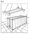
- Fig. 2 shows a container harness 1 when approaching a container 12.
- twist locks 2 of the container harness 1 must be accurately positioned on standardized corner fittings 11 of the container 12.
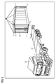
- Fig. 3 shows a container 12 when approaching a holding device 21 of a truck 20.
- corner fittings 11 of the container 10 must be accurately positioned over twist locks 2 of the truck 20.
- the container 12 is transported by means of a container harness 1 by a crane.
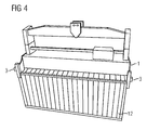
- Fig. 4 shows a container tableware 1, which is equipped with imaging sensors 3.
- the container harness 1 is deposited on a container 10.
- imaging sensors 3 only simple cameras are used.
- the imaging sensors are externally on the outer frame of the container harness attached so that they - if the container dishes as here in engagement with a container is - have a substantially vertically downwardly directed field of view past the container wall. The distance between frame and sensor axis thus forms an overhang.
- Fig. 5 shows mounting positions of imaging sensors 3 on a container tableware 1 from different perspectives. Partly also Twistlocks 2 of the container harness 1 are visible.
- FIG. 11 shows a determination of measured values from an environment of a container harness in a side view and the calculation of target position data to the anchoring positions.
- the container 12 is at the height 8 in engagement with the container harness 1.
- the height 8 may be the so-called. Safety height, in which the container is to move horizontally. This can vary from terminal to terminal, but is on the order of about 6 m.
- the imaging sensors 3 span a viewing area A, B bounded by the side lines a, b, a ', b' and deliver video images as measured values from the surroundings of the container harness to a computing unit 22.
- the holding device 21 is in this case that of an AGV.
- In the edge area are holes 7, which can serve as a railing attachment, for example.
- the holes 7 represent insofar natural markings. Preferably also applied markings as in Fig. 7 shown usable.
- the arithmetic unit 22 forms from the recorded measured values, the video images, data from which it calculates target position data for anchoring positions for the container harness. In the direction of travel, the container position in Fig. 6 currently an offset 23 to the anchoring position. Anchoring position is the position in which the anchoring devices (corner fittings 11 and twistlock 2) would be in engagement.
- the target position data are those data that are to be controlled to to move the container centering exactly to its anchoring position and thus on its anchoring device.
- the viewing area A along the usually profiled container wall and over the foot edge 24 of the container 12 generates on the surface of the holding device 21 a picture detail 9.
- the foot edge 24 is projected onto the surface of the holding device 21.
- the image section 9 has an extension 25 in the direction of travel, depending on the height 8, and comprises the marking 7.
- the markings 7 are known in shape and dimensions.
- the arithmetic unit 22 is thereby enabled to extract the markings from the measured values and to compare them with the marking parameters stored in the arithmetic unit 22 so as to recognize the markings 7 relevant for the further steps.
- On the silhouette of the image section 9 and the foot edge 24, the corner profile 26 of the container can be seen.
- the distance 27 between the relevant mark 7 and the corner profile 26 must have a certain target value in the anchoring position. From the current measure, the number of pixels between marking 7 and corner profile 26 at a certain height 8 can be calculated by the arithmetic unit, the target position data to the anchor positions and transferred to the crane control this enabled to lead the container harness over the anchoring position.
- Fig. 7 shows a determination of measured values of an environment of a container harness in the plan view and the calculation of target position data to the anchorage positions transverse to the direction of travel.
- the container 12 is again in height 8 in engagement with the container harness 1.
- the imaging sensors 3 span a limited by the side lines a, a ', a "field of view A and deliver video images as measurements of the environment of the container harness to a Arithmetic unit 22.
- the holding device 21 is again an AGV In the edge area this time, markings 7 in the form of squares are applied to the surface of the holding device 21.
- the container 12 has the offset 28 transversely to the anchoring position Driving direction.
- the twistlocks 2 are visible in the upper edge area, while they are covered by the container in the lower edge area (marked viewing area A).
- the viewing area A along the profiled container wall over the foot edge 24 of the container 12 generates on the surface of the holding device 21 a picture detail 29.
- the foot edge 24 is projected onto the surface of the holding device 21.
- the markers 7 are known in shape and dimensions.
- the arithmetic unit 22 is thereby enabled to extract the markings from the measured values and to compare them with the marking parameters stored in the arithmetic unit 22 so as to recognize the markings 7 relevant for the further steps. Furthermore, the arithmetic unit is able to determine the offset 30 between projected foot edge 24 and marking 7 from the dimensions of the marking.
- the mark 7 should have an extension of 10 cm, which should correspond to a pixel height of 500 pixels at a certain height 8. If now 30 200 pixels are measured for the offset, the current offset 30 can be determined to be 4 cm.
- the foot edge 24 should, so that the anchoring positions in the transverse direction are the same thinking over each other and the container can be discontinued, have a calculation unit known reference offset to mark 7. With knowledge of the current offset and the desired offset, the arithmetic unit can calculate the target position data on which the crane control moves the container harness via the anchoring positions.
Landscapes
- Engineering & Computer Science (AREA)
- Mechanical Engineering (AREA)
- Automation & Control Theory (AREA)
- Control And Safety Of Cranes (AREA)
- Length Measuring Devices By Optical Means (AREA)
Priority Applications (3)
| Application Number | Priority Date | Filing Date | Title |
|---|---|---|---|
| ES14186240.9T ES2627498T3 (es) | 2014-09-24 | 2014-09-24 | Método para la determinación óptica, automática, de una posición objetivo para un dispositivo de elevación de contenedores |
| EP14186240.9A EP3000762B1 (fr) | 2014-09-24 | 2014-09-24 | Procédé de détermination optique, automatique d'une position cible pour un palonnier de conteneur |
| CN201510613626.4A CN105438993B (zh) | 2014-09-24 | 2015-09-23 | 自动地光学确定集装箱吊具的目标位置的方法和系统 |
Applications Claiming Priority (1)
| Application Number | Priority Date | Filing Date | Title |
|---|---|---|---|
| EP14186240.9A EP3000762B1 (fr) | 2014-09-24 | 2014-09-24 | Procédé de détermination optique, automatique d'une position cible pour un palonnier de conteneur |
Publications (2)
| Publication Number | Publication Date |
|---|---|
| EP3000762A1 true EP3000762A1 (fr) | 2016-03-30 |
| EP3000762B1 EP3000762B1 (fr) | 2017-03-08 |
Family
ID=51619013
Family Applications (1)
| Application Number | Title | Priority Date | Filing Date |
|---|---|---|---|
| EP14186240.9A Active EP3000762B1 (fr) | 2014-09-24 | 2014-09-24 | Procédé de détermination optique, automatique d'une position cible pour un palonnier de conteneur |
Country Status (3)
| Country | Link |
|---|---|
| EP (1) | EP3000762B1 (fr) |
| CN (1) | CN105438993B (fr) |
| ES (1) | ES2627498T3 (fr) |
Cited By (12)
| Publication number | Priority date | Publication date | Assignee | Title |
|---|---|---|---|---|
| WO2018167366A1 (fr) * | 2017-03-16 | 2018-09-20 | Konecranes Global Oy | Surveillance d'un dispositif de transfert de conteneur lors de l'abaissement d'un conteneur sur une plate-forme de transport ou du levage de la plate-forme de transport |
| CN109384150A (zh) * | 2017-08-03 | 2019-02-26 | 南通通镭软件有限公司 | 自动化装卸的集装箱锁头图像定位和防吊起方法 |
| DE102018003640A1 (de) * | 2018-05-04 | 2019-11-07 | Wolfgang Wichner | Werkzeuggreifzange eines Transportkrans für Presswerkzeuge |
| EP3750842A1 (fr) * | 2019-06-11 | 2020-12-16 | Siemens Aktiengesellschaft | Chargement d'une charge à l'aide d'un système de grue |
| EP3713866A4 (fr) * | 2017-11-24 | 2021-08-25 | TMEIC Corporation | Procédés et systèmes de production de solutions de débarquement pour conteneurs sur des surfaces de débarquement |
| JP2021151909A (ja) * | 2020-03-24 | 2021-09-30 | 住友重機械搬送システム株式会社 | 遠隔操作システム及び遠隔操作方法 |
| CN114275673A (zh) * | 2021-10-30 | 2022-04-05 | 中冶(上海)钢结构科技有限公司 | 一种钢桁架吊装的定位辅助装置及其使用方法 |
| CN114604764A (zh) * | 2022-01-24 | 2022-06-10 | 杭州大杰智能传动科技有限公司 | 用于智能塔吊吊钩的松开自动检测控制方法及其装置 |
| CN115285833A (zh) * | 2022-06-30 | 2022-11-04 | 中联重科股份有限公司 | 吊臂转运系统和工程机械设备产线 |
| WO2023027062A1 (fr) * | 2021-08-25 | 2023-03-02 | 住友重機械搬送システム株式会社 | Palette pour le transfert de conteneurs |
| CN116119193A (zh) * | 2022-12-28 | 2023-05-16 | 中车西安车辆有限公司 | 一种基于投影的集装箱标记快速定位方法 |
| US20240307935A1 (en) * | 2023-03-16 | 2024-09-19 | Morgan Engineering Systems, Inc. | Method and apparatus for vertical roll storage |
Families Citing this family (10)
| Publication number | Priority date | Publication date | Assignee | Title |
|---|---|---|---|---|
| FI127422B (fi) * | 2016-12-20 | 2018-05-31 | Konecranes Global Oy | Menetelmä, tietokoneohjelma ja laitteisto nosturin ohjaamiseksi ja menetelmä nosturin päivittämiseksi |
| DE102017112661A1 (de) | 2017-06-08 | 2018-12-13 | Konecranes Global Corporation | Automatisch geführtes Portalhubgerät für Container und Verfahren zum Betrieb eines solchen Portalhubgeräts |
| CN107161861A (zh) * | 2017-06-30 | 2017-09-15 | 海航创新科技研究有限公司 | 云箱吊具的操作方法及云箱吊具 |
| CN110869306B (zh) * | 2017-07-04 | 2022-05-24 | Psa国际港务集团 | 用于远程起重机控制的装置和方法 |
| JP6965050B2 (ja) * | 2017-07-21 | 2021-11-10 | 株式会社タダノ | ガイド情報表示装置およびこれを備えたクレーンおよびガイド情報表示方法 |
| CN110113511A (zh) * | 2019-01-29 | 2019-08-09 | 上海驭矩信息科技有限公司 | 一款具有图像识别功能的新型三目相机的设计 |
| EP4013701B1 (fr) | 2019-08-16 | 2024-06-05 | Abb Schweiz Ag | Procédé et appareil permettant de déterminer l'emplacement d'un objet |
| CN111709996A (zh) * | 2020-06-16 | 2020-09-25 | 北京主线科技有限公司 | 一种检测集装箱位置的方法及装置 |
| CN215048146U (zh) * | 2021-02-04 | 2021-12-07 | 博众精工科技股份有限公司 | 一种吊具及换电站 |
| CN116621032B (zh) * | 2023-05-25 | 2024-04-09 | 广州港股份有限公司 | 适用于集装箱吊具精准定位特性且提高调整效率的方法 |
Citations (5)
| Publication number | Priority date | Publication date | Assignee | Title |
|---|---|---|---|---|
| US20020191813A1 (en) * | 2000-10-27 | 2002-12-19 | Kouji Uchida | Container position measuring method and device for cargo crane and container landing/stacking method |
| JP2005263373A (ja) * | 2004-03-17 | 2005-09-29 | Mitsui Eng & Shipbuild Co Ltd | コンテナ昇降操作支援方法およびコンテナスプレッダ位置決め装置 |
| JP2008168952A (ja) * | 2007-01-05 | 2008-07-24 | Mitsubishi Heavy Ind Ltd | 位置ずれ量算出方法およびクレーン並びに搬送台車 |
| EP2574587A1 (fr) | 2011-09-30 | 2013-04-03 | Siemens Aktiengesellschaft | Procédé de détermination d'une position cible pour un palonnier de conteneur et le palonnier de conteneur |
| EP2724972A1 (fr) | 2012-10-25 | 2014-04-30 | Lase GmbH Industrielle Lasertechnik | Procédé de détermination de position dans lequel un conteneur ISO doit être placé sur un convoyeur, ainsi qu'installation de mesure à scanner laser 3D à cet effet |
Family Cites Families (2)
| Publication number | Priority date | Publication date | Assignee | Title |
|---|---|---|---|---|
| JP4598999B2 (ja) * | 2001-07-18 | 2010-12-15 | 三菱重工業株式会社 | クレーン及びクレーンの制御方法 |
| JP5689534B2 (ja) * | 2011-09-29 | 2015-03-25 | 住友重機械工業株式会社 | 物体検出装置を搭載する天井クレーン |
-
2014
- 2014-09-24 ES ES14186240.9T patent/ES2627498T3/es active Active
- 2014-09-24 EP EP14186240.9A patent/EP3000762B1/fr active Active
-
2015
- 2015-09-23 CN CN201510613626.4A patent/CN105438993B/zh active Active
Patent Citations (5)
| Publication number | Priority date | Publication date | Assignee | Title |
|---|---|---|---|---|
| US20020191813A1 (en) * | 2000-10-27 | 2002-12-19 | Kouji Uchida | Container position measuring method and device for cargo crane and container landing/stacking method |
| JP2005263373A (ja) * | 2004-03-17 | 2005-09-29 | Mitsui Eng & Shipbuild Co Ltd | コンテナ昇降操作支援方法およびコンテナスプレッダ位置決め装置 |
| JP2008168952A (ja) * | 2007-01-05 | 2008-07-24 | Mitsubishi Heavy Ind Ltd | 位置ずれ量算出方法およびクレーン並びに搬送台車 |
| EP2574587A1 (fr) | 2011-09-30 | 2013-04-03 | Siemens Aktiengesellschaft | Procédé de détermination d'une position cible pour un palonnier de conteneur et le palonnier de conteneur |
| EP2724972A1 (fr) | 2012-10-25 | 2014-04-30 | Lase GmbH Industrielle Lasertechnik | Procédé de détermination de position dans lequel un conteneur ISO doit être placé sur un convoyeur, ainsi qu'installation de mesure à scanner laser 3D à cet effet |
Non-Patent Citations (1)
| Title |
|---|
| JÖRG KRÜGER; MIKE NEUENDORF: "Kameragestützte Automatisierung von Containerkranen - Potentiale, Technologien, Rahmenbedingungen", INTERNATIONALE KRAN-FACHTAGUNG 2011, IST EINE KAMERAGESTÜTZTE, AUTOMATISCHE ERKENNUNG VON BE- UND ENTLADEPOSITIONEN AUF EINEM LKW BEKANNT, 2011 |
Cited By (22)
| Publication number | Priority date | Publication date | Assignee | Title |
|---|---|---|---|---|
| WO2018167366A1 (fr) * | 2017-03-16 | 2018-09-20 | Konecranes Global Oy | Surveillance d'un dispositif de transfert de conteneur lors de l'abaissement d'un conteneur sur une plate-forme de transport ou du levage de la plate-forme de transport |
| US11262189B2 (en) | 2017-03-16 | 2022-03-01 | Konecranes Global Oy | Monitoring container transfer device on lowering container onto transport platform or lifting away from transport platform |
| CN109384150A (zh) * | 2017-08-03 | 2019-02-26 | 南通通镭软件有限公司 | 自动化装卸的集装箱锁头图像定位和防吊起方法 |
| EP3713866A4 (fr) * | 2017-11-24 | 2021-08-25 | TMEIC Corporation | Procédés et systèmes de production de solutions de débarquement pour conteneurs sur des surfaces de débarquement |
| US11873195B2 (en) | 2017-11-24 | 2024-01-16 | Tmeic Corporation | Methods and systems for generating landing solutions for containers on landing surfaces |
| DE102018003640A1 (de) * | 2018-05-04 | 2019-11-07 | Wolfgang Wichner | Werkzeuggreifzange eines Transportkrans für Presswerkzeuge |
| DE102018003640B4 (de) | 2018-05-04 | 2020-06-04 | Wolfgang Wichner | Werkzeuggreifzange eines Transportkrans für Presswerkzeuge |
| EP3566999B1 (fr) * | 2018-05-04 | 2024-07-10 | CATS Crane Automation Technology Systems GmbH & Co. KG | Pince de préhension d'outil d'une grue de transport pour outils de presse |
| EP3750842A1 (fr) * | 2019-06-11 | 2020-12-16 | Siemens Aktiengesellschaft | Chargement d'une charge à l'aide d'un système de grue |
| US11584622B2 (en) | 2019-06-11 | 2023-02-21 | Siemens Aktiengesellschaft | Loading of a load with a crane system |
| JP2021151909A (ja) * | 2020-03-24 | 2021-09-30 | 住友重機械搬送システム株式会社 | 遠隔操作システム及び遠隔操作方法 |
| WO2021193294A1 (fr) * | 2020-03-24 | 2021-09-30 | 住友重機械搬送システム株式会社 | Système de commande à distance et procédé de commande à distance |
| JP7616969B2 (ja) | 2021-08-25 | 2025-01-17 | 住友重機械搬送システム株式会社 | コンテナ移載用パレット |
| WO2023027062A1 (fr) * | 2021-08-25 | 2023-03-02 | 住友重機械搬送システム株式会社 | Palette pour le transfert de conteneurs |
| CN114275673A (zh) * | 2021-10-30 | 2022-04-05 | 中冶(上海)钢结构科技有限公司 | 一种钢桁架吊装的定位辅助装置及其使用方法 |
| CN114604764A (zh) * | 2022-01-24 | 2022-06-10 | 杭州大杰智能传动科技有限公司 | 用于智能塔吊吊钩的松开自动检测控制方法及其装置 |
| CN114604764B (zh) * | 2022-01-24 | 2023-06-02 | 杭州大杰智能传动科技有限公司 | 用于智能塔吊吊钩的松开自动检测控制方法及其装置 |
| CN115285833A (zh) * | 2022-06-30 | 2022-11-04 | 中联重科股份有限公司 | 吊臂转运系统和工程机械设备产线 |
| CN116119193A (zh) * | 2022-12-28 | 2023-05-16 | 中车西安车辆有限公司 | 一种基于投影的集装箱标记快速定位方法 |
| CN116119193B (zh) * | 2022-12-28 | 2025-09-16 | 中车西安车辆有限公司 | 一种基于投影的集装箱标记快速定位方法 |
| US20240307935A1 (en) * | 2023-03-16 | 2024-09-19 | Morgan Engineering Systems, Inc. | Method and apparatus for vertical roll storage |
| US12576436B2 (en) * | 2023-03-16 | 2026-03-17 | Morgan Engineering Systems, Inc. | Method and apparatus for vertical roll storage |
Also Published As
| Publication number | Publication date |
|---|---|
| EP3000762B1 (fr) | 2017-03-08 |
| ES2627498T3 (es) | 2017-07-28 |
| CN105438993A (zh) | 2016-03-30 |
| CN105438993B (zh) | 2017-07-28 |
Similar Documents
| Publication | Publication Date | Title |
|---|---|---|
| EP3000762B1 (fr) | Procédé de détermination optique, automatique d'une position cible pour un palonnier de conteneur | |
| EP2574587B1 (fr) | Procédé de détermination d'une position cible pour un palonnier de conteneur et le palonnier de conteneur | |
| EP3260357B1 (fr) | Véhicule comprenant un système de man uvre | |
| EP2724972B1 (fr) | Procédé de détermination de la position dans laquelle un conteneur ISO est à déposer sur un véhicule porteur, ainsi qu'installation de mesure à scanner laser 3D à cet effet | |
| EP2910512B1 (fr) | Procédé d'étalonnage de scanners laser sur une grue de manutention de conteneurs | |
| EP0656868B1 (fr) | Procede et dispositif de commande d'un pont dechargeur pour conteneurs | |
| DE60108159T2 (de) | Verfahren und vorrichtung zum messen von der position eines containers für ladekräne verfahren zum absetzen/stapeln von cotainern | |
| DE102007046287B4 (de) | Verfahren zur Kalibrierung einer Sensoranordnung | |
| DE10323641A1 (de) | Bewegliche Sensoreinrichtung am Lastmittel eines Gabelstaplers | |
| EP3894349B1 (fr) | Système de chargement de conteneurs et procédé de surveillance du fonctionnement dans ce dernier | |
| DE102007021693A1 (de) | Hilfssystem zur Lagebestimmung eines Fahrzeugs | |
| DE102008019373A1 (de) | Messvorrichtung und Verfahren zum Kalibrieren einer Messvorrichtung eines Krans | |
| DE102018210340B4 (de) | Verfahren und System zum Ermitteln einer Relativpose zwischen einem Zielobjekt und einem Fahrzeug | |
| EP4402087A1 (fr) | Grue | |
| WO2018185088A1 (fr) | Procédé d'enlèvement et de pose, de manière précise en position, d'un conteneur par le biais d'un chariot gerbeur cavalier et chariot gerbeur cavalier associé | |
| DE19916999A1 (de) | Verfahren zur Bestimmung der Lage eines Fahrzeuges | |
| DE102012003650B4 (de) | Verfahren und Vorrichtung zum überwachten vertikalen Anheben eines Normcontainers | |
| DE10202399A1 (de) | Einrichtung und Verfahren zur Positionierung von Transportfahrzeugen | |
| DE102007060856A1 (de) | Verfahren und Sensoranordnung zur Ermittlung von Fahrspuren | |
| DE112018000580T5 (de) | Bewegbare Hebevorrichtung, Anordnung und Verfahren | |
| DE102007046288B4 (de) | Verfahren und Sensoranordnung zur Vermessung optischer Merkmale | |
| EP3103757A1 (fr) | Procédé et système de détection d'un levage d'un véhicule porte-conteneur | |
| DE202007019542U1 (de) | Hilfssystem zur Lagebestimmung eines Fahrzeugs | |
| DE202024102989U1 (de) | Vorrichtung zum Überwachen einer zu verladenden Fracht |
Legal Events
| Date | Code | Title | Description |
|---|---|---|---|
| PUAI | Public reference made under article 153(3) epc to a published international application that has entered the european phase |
Free format text: ORIGINAL CODE: 0009012 |
|
| 17P | Request for examination filed |
Effective date: 20150320 |
|
| AK | Designated contracting states |
Kind code of ref document: A1 Designated state(s): AL AT BE BG CH CY CZ DE DK EE ES FI FR GB GR HR HU IE IS IT LI LT LU LV MC MK MT NL NO PL PT RO RS SE SI SK SM TR |
|
| AX | Request for extension of the european patent |
Extension state: BA ME |
|
| GRAP | Despatch of communication of intention to grant a patent |
Free format text: ORIGINAL CODE: EPIDOSNIGR1 |
|
| INTG | Intention to grant announced |
Effective date: 20161004 |
|
| GRAS | Grant fee paid |
Free format text: ORIGINAL CODE: EPIDOSNIGR3 |
|
| GRAA | (expected) grant |
Free format text: ORIGINAL CODE: 0009210 |
|
| AK | Designated contracting states |
Kind code of ref document: B1 Designated state(s): AL AT BE BG CH CY CZ DE DK EE ES FI FR GB GR HR HU IE IS IT LI LT LU LV MC MK MT NL NO PL PT RO RS SE SI SK SM TR |
|
| REG | Reference to a national code |
Ref country code: GB Ref legal event code: FG4D Free format text: NOT ENGLISH |
|
| REG | Reference to a national code |
Ref country code: CH Ref legal event code: EP Ref country code: AT Ref legal event code: REF Ref document number: 873320 Country of ref document: AT Kind code of ref document: T Effective date: 20170315 |
|
| REG | Reference to a national code |
Ref country code: IE Ref legal event code: FG4D Free format text: LANGUAGE OF EP DOCUMENT: GERMAN |
|
| REG | Reference to a national code |
Ref country code: DE Ref legal event code: R096 Ref document number: 502014002903 Country of ref document: DE |
|
| REG | Reference to a national code |
Ref country code: NL Ref legal event code: FP |
|
| REG | Reference to a national code |
Ref country code: LT Ref legal event code: MG4D |
|
| REG | Reference to a national code |
Ref country code: ES Ref legal event code: FG2A Ref document number: 2627498 Country of ref document: ES Kind code of ref document: T3 Effective date: 20170728 |
|
| PG25 | Lapsed in a contracting state [announced via postgrant information from national office to epo] |
Ref country code: GR Free format text: LAPSE BECAUSE OF FAILURE TO SUBMIT A TRANSLATION OF THE DESCRIPTION OR TO PAY THE FEE WITHIN THE PRESCRIBED TIME-LIMIT Effective date: 20170609 Ref country code: NO Free format text: LAPSE BECAUSE OF FAILURE TO SUBMIT A TRANSLATION OF THE DESCRIPTION OR TO PAY THE FEE WITHIN THE PRESCRIBED TIME-LIMIT Effective date: 20170608 Ref country code: LT Free format text: LAPSE BECAUSE OF FAILURE TO SUBMIT A TRANSLATION OF THE DESCRIPTION OR TO PAY THE FEE WITHIN THE PRESCRIBED TIME-LIMIT Effective date: 20170308 Ref country code: HR Free format text: LAPSE BECAUSE OF FAILURE TO SUBMIT A TRANSLATION OF THE DESCRIPTION OR TO PAY THE FEE WITHIN THE PRESCRIBED TIME-LIMIT Effective date: 20170308 Ref country code: FI Free format text: LAPSE BECAUSE OF FAILURE TO SUBMIT A TRANSLATION OF THE DESCRIPTION OR TO PAY THE FEE WITHIN THE PRESCRIBED TIME-LIMIT Effective date: 20170308 |
|
| RAP2 | Party data changed (patent owner data changed or rights of a patent transferred) |
Owner name: SIEMENS AKTIENGESELLSCHAFT |
|
| PG25 | Lapsed in a contracting state [announced via postgrant information from national office to epo] |
Ref country code: SE Free format text: LAPSE BECAUSE OF FAILURE TO SUBMIT A TRANSLATION OF THE DESCRIPTION OR TO PAY THE FEE WITHIN THE PRESCRIBED TIME-LIMIT Effective date: 20170308 Ref country code: BG Free format text: LAPSE BECAUSE OF FAILURE TO SUBMIT A TRANSLATION OF THE DESCRIPTION OR TO PAY THE FEE WITHIN THE PRESCRIBED TIME-LIMIT Effective date: 20170608 Ref country code: LV Free format text: LAPSE BECAUSE OF FAILURE TO SUBMIT A TRANSLATION OF THE DESCRIPTION OR TO PAY THE FEE WITHIN THE PRESCRIBED TIME-LIMIT Effective date: 20170308 Ref country code: RS Free format text: LAPSE BECAUSE OF FAILURE TO SUBMIT A TRANSLATION OF THE DESCRIPTION OR TO PAY THE FEE WITHIN THE PRESCRIBED TIME-LIMIT Effective date: 20170308 |
|
| REG | Reference to a national code |
Ref country code: CH Ref legal event code: NV Representative=s name: SIEMENS SCHWEIZ AG, CH Ref country code: CH Ref legal event code: PCOW Free format text: NEW ADDRESS: WERNER-VON-SIEMENS-STRASSE 1, 80333 MUENCHEN (DE) |
|
| PG25 | Lapsed in a contracting state [announced via postgrant information from national office to epo] |
Ref country code: RO Free format text: LAPSE BECAUSE OF FAILURE TO SUBMIT A TRANSLATION OF THE DESCRIPTION OR TO PAY THE FEE WITHIN THE PRESCRIBED TIME-LIMIT Effective date: 20170308 Ref country code: EE Free format text: LAPSE BECAUSE OF FAILURE TO SUBMIT A TRANSLATION OF THE DESCRIPTION OR TO PAY THE FEE WITHIN THE PRESCRIBED TIME-LIMIT Effective date: 20170308 Ref country code: SK Free format text: LAPSE BECAUSE OF FAILURE TO SUBMIT A TRANSLATION OF THE DESCRIPTION OR TO PAY THE FEE WITHIN THE PRESCRIBED TIME-LIMIT Effective date: 20170308 Ref country code: CZ Free format text: LAPSE BECAUSE OF FAILURE TO SUBMIT A TRANSLATION OF THE DESCRIPTION OR TO PAY THE FEE WITHIN THE PRESCRIBED TIME-LIMIT Effective date: 20170308 |
|
| PG25 | Lapsed in a contracting state [announced via postgrant information from national office to epo] |
Ref country code: PT Free format text: LAPSE BECAUSE OF FAILURE TO SUBMIT A TRANSLATION OF THE DESCRIPTION OR TO PAY THE FEE WITHIN THE PRESCRIBED TIME-LIMIT Effective date: 20170710 Ref country code: PL Free format text: LAPSE BECAUSE OF FAILURE TO SUBMIT A TRANSLATION OF THE DESCRIPTION OR TO PAY THE FEE WITHIN THE PRESCRIBED TIME-LIMIT Effective date: 20170308 Ref country code: SM Free format text: LAPSE BECAUSE OF FAILURE TO SUBMIT A TRANSLATION OF THE DESCRIPTION OR TO PAY THE FEE WITHIN THE PRESCRIBED TIME-LIMIT Effective date: 20170308 Ref country code: IS Free format text: LAPSE BECAUSE OF FAILURE TO SUBMIT A TRANSLATION OF THE DESCRIPTION OR TO PAY THE FEE WITHIN THE PRESCRIBED TIME-LIMIT Effective date: 20170708 |
|
| REG | Reference to a national code |
Ref country code: DE Ref legal event code: R097 Ref document number: 502014002903 Country of ref document: DE |
|
| PLBE | No opposition filed within time limit |
Free format text: ORIGINAL CODE: 0009261 |
|
| STAA | Information on the status of an ep patent application or granted ep patent |
Free format text: STATUS: NO OPPOSITION FILED WITHIN TIME LIMIT |
|
| PG25 | Lapsed in a contracting state [announced via postgrant information from national office to epo] |
Ref country code: DK Free format text: LAPSE BECAUSE OF FAILURE TO SUBMIT A TRANSLATION OF THE DESCRIPTION OR TO PAY THE FEE WITHIN THE PRESCRIBED TIME-LIMIT Effective date: 20170308 |
|
| 26N | No opposition filed |
Effective date: 20171211 |
|
| PG25 | Lapsed in a contracting state [announced via postgrant information from national office to epo] |
Ref country code: SI Free format text: LAPSE BECAUSE OF FAILURE TO SUBMIT A TRANSLATION OF THE DESCRIPTION OR TO PAY THE FEE WITHIN THE PRESCRIBED TIME-LIMIT Effective date: 20170308 |
|
| REG | Reference to a national code |
Ref country code: CH Ref legal event code: PL |
|
| PG25 | Lapsed in a contracting state [announced via postgrant information from national office to epo] |
Ref country code: MC Free format text: LAPSE BECAUSE OF FAILURE TO SUBMIT A TRANSLATION OF THE DESCRIPTION OR TO PAY THE FEE WITHIN THE PRESCRIBED TIME-LIMIT Effective date: 20170308 |
|
| REG | Reference to a national code |
Ref country code: IE Ref legal event code: MM4A |
|
| REG | Reference to a national code |
Ref country code: BE Ref legal event code: MM Effective date: 20170930 |
|
| PG25 | Lapsed in a contracting state [announced via postgrant information from national office to epo] |
Ref country code: LU Free format text: LAPSE BECAUSE OF NON-PAYMENT OF DUE FEES Effective date: 20170924 |
|
| REG | Reference to a national code |
Ref country code: FR Ref legal event code: ST Effective date: 20180531 |
|
| PG25 | Lapsed in a contracting state [announced via postgrant information from national office to epo] |
Ref country code: IE Free format text: LAPSE BECAUSE OF NON-PAYMENT OF DUE FEES Effective date: 20170924 Ref country code: LI Free format text: LAPSE BECAUSE OF NON-PAYMENT OF DUE FEES Effective date: 20170930 Ref country code: CH Free format text: LAPSE BECAUSE OF NON-PAYMENT OF DUE FEES Effective date: 20170930 |
|
| PG25 | Lapsed in a contracting state [announced via postgrant information from national office to epo] |
Ref country code: FR Free format text: LAPSE BECAUSE OF NON-PAYMENT OF DUE FEES Effective date: 20171002 Ref country code: BE Free format text: LAPSE BECAUSE OF NON-PAYMENT OF DUE FEES Effective date: 20170930 |
|
| PG25 | Lapsed in a contracting state [announced via postgrant information from national office to epo] |
Ref country code: MT Free format text: LAPSE BECAUSE OF FAILURE TO SUBMIT A TRANSLATION OF THE DESCRIPTION OR TO PAY THE FEE WITHIN THE PRESCRIBED TIME-LIMIT Effective date: 20170308 |
|
| PGFP | Annual fee paid to national office [announced via postgrant information from national office to epo] |
Ref country code: IT Payment date: 20180926 Year of fee payment: 5 |
|
| PGFP | Annual fee paid to national office [announced via postgrant information from national office to epo] |
Ref country code: ES Payment date: 20181217 Year of fee payment: 5 |
|
| PG25 | Lapsed in a contracting state [announced via postgrant information from national office to epo] |
Ref country code: HU Free format text: LAPSE BECAUSE OF FAILURE TO SUBMIT A TRANSLATION OF THE DESCRIPTION OR TO PAY THE FEE WITHIN THE PRESCRIBED TIME-LIMIT; INVALID AB INITIO Effective date: 20140924 |
|
| PG25 | Lapsed in a contracting state [announced via postgrant information from national office to epo] |
Ref country code: CY Free format text: LAPSE BECAUSE OF FAILURE TO SUBMIT A TRANSLATION OF THE DESCRIPTION OR TO PAY THE FEE WITHIN THE PRESCRIBED TIME-LIMIT Effective date: 20170308 |
|
| PG25 | Lapsed in a contracting state [announced via postgrant information from national office to epo] |
Ref country code: MK Free format text: LAPSE BECAUSE OF FAILURE TO SUBMIT A TRANSLATION OF THE DESCRIPTION OR TO PAY THE FEE WITHIN THE PRESCRIBED TIME-LIMIT Effective date: 20170308 |
|
| PG25 | Lapsed in a contracting state [announced via postgrant information from national office to epo] |
Ref country code: TR Free format text: LAPSE BECAUSE OF FAILURE TO SUBMIT A TRANSLATION OF THE DESCRIPTION OR TO PAY THE FEE WITHIN THE PRESCRIBED TIME-LIMIT Effective date: 20170308 |
|
| PG25 | Lapsed in a contracting state [announced via postgrant information from national office to epo] |
Ref country code: AL Free format text: LAPSE BECAUSE OF FAILURE TO SUBMIT A TRANSLATION OF THE DESCRIPTION OR TO PAY THE FEE WITHIN THE PRESCRIBED TIME-LIMIT Effective date: 20170308 |
|
| PG25 | Lapsed in a contracting state [announced via postgrant information from national office to epo] |
Ref country code: IT Free format text: LAPSE BECAUSE OF NON-PAYMENT OF DUE FEES Effective date: 20190924 |
|
| GBPC | Gb: european patent ceased through non-payment of renewal fee |
Effective date: 20190924 |
|
| PG25 | Lapsed in a contracting state [announced via postgrant information from national office to epo] |
Ref country code: GB Free format text: LAPSE BECAUSE OF NON-PAYMENT OF DUE FEES Effective date: 20190924 |
|
| REG | Reference to a national code |
Ref country code: AT Ref legal event code: MM01 Ref document number: 873320 Country of ref document: AT Kind code of ref document: T Effective date: 20190924 |
|
| REG | Reference to a national code |
Ref country code: ES Ref legal event code: FD2A Effective date: 20210128 |
|
| PG25 | Lapsed in a contracting state [announced via postgrant information from national office to epo] |
Ref country code: AT Free format text: LAPSE BECAUSE OF NON-PAYMENT OF DUE FEES Effective date: 20190924 |
|
| PG25 | Lapsed in a contracting state [announced via postgrant information from national office to epo] |
Ref country code: ES Free format text: LAPSE BECAUSE OF NON-PAYMENT OF DUE FEES Effective date: 20190925 |
|
| PGFP | Annual fee paid to national office [announced via postgrant information from national office to epo] |
Ref country code: NL Payment date: 20250902 Year of fee payment: 12 |
|
| PGFP | Annual fee paid to national office [announced via postgrant information from national office to epo] |
Ref country code: DE Payment date: 20251120 Year of fee payment: 12 |