EP3000971A1 - Structure de refroidissement de film à double jet et son procédé de production - Google Patents
Structure de refroidissement de film à double jet et son procédé de production Download PDFInfo
- Publication number
- EP3000971A1 EP3000971A1 EP14800768.5A EP14800768A EP3000971A1 EP 3000971 A1 EP3000971 A1 EP 3000971A1 EP 14800768 A EP14800768 A EP 14800768A EP 3000971 A1 EP3000971 A1 EP 3000971A1
- Authority
- EP
- European Patent Office
- Prior art keywords
- branch
- wall surface
- passage
- passages
- main passage
- Prior art date
- Legal status (The legal status is an assumption and is not a legal conclusion. Google has not performed a legal analysis and makes no representation as to the accuracy of the status listed.)
- Granted
Links
Images


Classifications
-
- F—MECHANICAL ENGINEERING; LIGHTING; HEATING; WEAPONS; BLASTING
- F01—MACHINES OR ENGINES IN GENERAL; ENGINE PLANTS IN GENERAL; STEAM ENGINES
- F01D—NON-POSITIVE DISPLACEMENT MACHINES OR ENGINES, e.g. STEAM TURBINES
- F01D5/00—Blades; Blade-carrying members; Heating, heat-insulating, cooling or antivibration means on the blades or the members
- F01D5/12—Blades
- F01D5/14—Form or construction
- F01D5/18—Hollow blades, i.e. blades with cooling or heating channels or cavities; Heating, heat-insulating or cooling means on blades
- F01D5/186—Film cooling
-
- B—PERFORMING OPERATIONS; TRANSPORTING
- B23—MACHINE TOOLS; METAL-WORKING NOT OTHERWISE PROVIDED FOR
- B23H—WORKING OF METAL BY THE ACTION OF A HIGH CONCENTRATION OF ELECTRIC CURRENT ON A WORKPIECE USING AN ELECTRODE WHICH TAKES THE PLACE OF A TOOL; SUCH WORKING COMBINED WITH OTHER FORMS OF WORKING OF METAL
- B23H1/00—Electrical discharge machining, i.e. removing metal with a series of rapidly recurring electrical discharges between an electrode and a workpiece in the presence of a fluid dielectric
- B23H1/04—Electrodes specially adapted therefor or their manufacture
-
- B—PERFORMING OPERATIONS; TRANSPORTING
- B23—MACHINE TOOLS; METAL-WORKING NOT OTHERWISE PROVIDED FOR
- B23H—WORKING OF METAL BY THE ACTION OF A HIGH CONCENTRATION OF ELECTRIC CURRENT ON A WORKPIECE USING AN ELECTRODE WHICH TAKES THE PLACE OF A TOOL; SUCH WORKING COMBINED WITH OTHER FORMS OF WORKING OF METAL
- B23H9/00—Machining specially adapted for treating particular metal objects or for obtaining special effects or results on metal objects
- B23H9/10—Working turbine blades or nozzles
-
- B—PERFORMING OPERATIONS; TRANSPORTING
- B23—MACHINE TOOLS; METAL-WORKING NOT OTHERWISE PROVIDED FOR
- B23H—WORKING OF METAL BY THE ACTION OF A HIGH CONCENTRATION OF ELECTRIC CURRENT ON A WORKPIECE USING AN ELECTRODE WHICH TAKES THE PLACE OF A TOOL; SUCH WORKING COMBINED WITH OTHER FORMS OF WORKING OF METAL
- B23H9/00—Machining specially adapted for treating particular metal objects or for obtaining special effects or results on metal objects
- B23H9/14—Making holes
-
- F—MECHANICAL ENGINEERING; LIGHTING; HEATING; WEAPONS; BLASTING
- F01—MACHINES OR ENGINES IN GENERAL; ENGINE PLANTS IN GENERAL; STEAM ENGINES
- F01D—NON-POSITIVE DISPLACEMENT MACHINES OR ENGINES, e.g. STEAM TURBINES
- F01D9/00—Stators
- F01D9/06—Fluid supply conduits to nozzles or the like
- F01D9/065—Fluid supply or removal conduits traversing the working fluid flow, e.g. for lubrication-, cooling-, or sealing fluids
-
- F—MECHANICAL ENGINEERING; LIGHTING; HEATING; WEAPONS; BLASTING
- F23—COMBUSTION APPARATUS; COMBUSTION PROCESSES
- F23R—GENERATING COMBUSTION PRODUCTS OF HIGH PRESSURE OR HIGH VELOCITY, e.g. GAS-TURBINE COMBUSTION CHAMBERS
- F23R3/00—Continuous combustion chambers using liquid or gaseous fuel
- F23R3/02—Continuous combustion chambers using liquid or gaseous fuel characterised by the air-flow or gas-flow configuration
- F23R3/04—Air inlet arrangements
- F23R3/06—Arrangement of apertures along the flame tube
-
- F—MECHANICAL ENGINEERING; LIGHTING; HEATING; WEAPONS; BLASTING
- F05—INDEXING SCHEMES RELATING TO ENGINES OR PUMPS IN VARIOUS SUBCLASSES OF CLASSES F01-F04
- F05D—INDEXING SCHEME FOR ASPECTS RELATING TO NON-POSITIVE-DISPLACEMENT MACHINES OR ENGINES, GAS-TURBINES OR JET-PROPULSION PLANTS
- F05D2230/00—Manufacture
- F05D2230/10—Manufacture by removing material
- F05D2230/12—Manufacture by removing material by spark erosion methods
-
- F—MECHANICAL ENGINEERING; LIGHTING; HEATING; WEAPONS; BLASTING
- F05—INDEXING SCHEMES RELATING TO ENGINES OR PUMPS IN VARIOUS SUBCLASSES OF CLASSES F01-F04
- F05D—INDEXING SCHEME FOR ASPECTS RELATING TO NON-POSITIVE-DISPLACEMENT MACHINES OR ENGINES, GAS-TURBINES OR JET-PROPULSION PLANTS
- F05D2240/00—Components
- F05D2240/10—Stators
- F05D2240/11—Shroud seal segments
-
- F—MECHANICAL ENGINEERING; LIGHTING; HEATING; WEAPONS; BLASTING
- F05—INDEXING SCHEMES RELATING TO ENGINES OR PUMPS IN VARIOUS SUBCLASSES OF CLASSES F01-F04
- F05D—INDEXING SCHEME FOR ASPECTS RELATING TO NON-POSITIVE-DISPLACEMENT MACHINES OR ENGINES, GAS-TURBINES OR JET-PROPULSION PLANTS
- F05D2240/00—Components
- F05D2240/80—Platforms for stationary or moving blades
- F05D2240/81—Cooled platforms
-
- F—MECHANICAL ENGINEERING; LIGHTING; HEATING; WEAPONS; BLASTING
- F05—INDEXING SCHEMES RELATING TO ENGINES OR PUMPS IN VARIOUS SUBCLASSES OF CLASSES F01-F04
- F05D—INDEXING SCHEME FOR ASPECTS RELATING TO NON-POSITIVE-DISPLACEMENT MACHINES OR ENGINES, GAS-TURBINES OR JET-PROPULSION PLANTS
- F05D2250/00—Geometry
- F05D2250/10—Two-dimensional
- F05D2250/14—Two-dimensional elliptical
-
- F—MECHANICAL ENGINEERING; LIGHTING; HEATING; WEAPONS; BLASTING
- F05—INDEXING SCHEMES RELATING TO ENGINES OR PUMPS IN VARIOUS SUBCLASSES OF CLASSES F01-F04
- F05D—INDEXING SCHEME FOR ASPECTS RELATING TO NON-POSITIVE-DISPLACEMENT MACHINES OR ENGINES, GAS-TURBINES OR JET-PROPULSION PLANTS
- F05D2250/00—Geometry
- F05D2250/20—Three-dimensional
- F05D2250/23—Three-dimensional prismatic
- F05D2250/231—Three-dimensional prismatic cylindrical
-
- F—MECHANICAL ENGINEERING; LIGHTING; HEATING; WEAPONS; BLASTING
- F05—INDEXING SCHEMES RELATING TO ENGINES OR PUMPS IN VARIOUS SUBCLASSES OF CLASSES F01-F04
- F05D—INDEXING SCHEME FOR ASPECTS RELATING TO NON-POSITIVE-DISPLACEMENT MACHINES OR ENGINES, GAS-TURBINES OR JET-PROPULSION PLANTS
- F05D2250/00—Geometry
- F05D2250/70—Shape
- F05D2250/75—Shape given by its similarity to a letter, e.g. T-shaped
-
- F—MECHANICAL ENGINEERING; LIGHTING; HEATING; WEAPONS; BLASTING
- F05—INDEXING SCHEMES RELATING TO ENGINES OR PUMPS IN VARIOUS SUBCLASSES OF CLASSES F01-F04
- F05D—INDEXING SCHEME FOR ASPECTS RELATING TO NON-POSITIVE-DISPLACEMENT MACHINES OR ENGINES, GAS-TURBINES OR JET-PROPULSION PLANTS
- F05D2260/00—Function
- F05D2260/20—Heat transfer, e.g. cooling
- F05D2260/202—Heat transfer, e.g. cooling by film cooling
-
- F—MECHANICAL ENGINEERING; LIGHTING; HEATING; WEAPONS; BLASTING
- F23—COMBUSTION APPARATUS; COMBUSTION PROCESSES
- F23R—GENERATING COMBUSTION PRODUCTS OF HIGH PRESSURE OR HIGH VELOCITY, e.g. GAS-TURBINE COMBUSTION CHAMBERS
- F23R2900/00—Special features of, or arrangements for continuous combustion chambers; Combustion processes therefor
- F23R2900/03042—Film cooled combustion chamber walls or domes
Definitions
- the present invention relates to a film cooling structure in which injection ports are provided on a wall surface facing a high-temperature gas passage, such as a rotor blade, a stator blade, and an inner tube of a combustor in a gas turbine engine, and cooling of the wall surface is performed by causing a cooling medium injected from the injection ports to flow along the wall surface.
- a high-temperature gas passage such as a rotor blade, a stator blade, and an inner tube of a combustor in a gas turbine engine
- injection ports are provided on a wall surface such as a rotor blade in a gas turbine engine (hereinafter simply referred to as "gas turbine") such that the injection ports are oriented in the same direction.
- a film flow of a cooling medium such as air injected from these injection ports cools the wall surface, which is exposed to a high-temperature gas.
- a structure has generally been proposed in which a round hole is provided in a wall so as to be inclined toward a downstream side of a high-temperature gas, and a cooling medium is injected from an oval injection port opened at the surface of the wall.
- cooling efficiency of this cooling structure is poor.
- cooling effect can be enhanced by increasing the width of the cooling medium along the wall surface.
- Tg is a temperature of the high-temperature gas
- Tf is a surface temperature of the wall surface
- Tc is a temperature of the cooling medium on the wall surface.
- the shape of a center portion of the injection port is not a simple oval but is composed of a plurality of curves each having a radius of curvature (paragraphs 0016 to 0017)
- the number of manufacturing processes increases.
- film efficiency can be enhanced by suppressing the cooling medium from being separated from the wall surface.
- the distribution portion is undercut as viewed from the wall surface side
- an object of the present invention is to provide a film cooling structure which is capable of efficiently cooling a wall surface, such as a rotor blade or a stator blade of a gas turbine, by suppressing cooling medium film from being separated from the wall surface, and which is easily manufactured.
- a double-jet film cooling structure includes:
- the transverse injection angles of the injection directions of the cooling medium from the pair of jet holes with respect to the flow direction of the high-temperature gas, along the wall surface are set to be oriented in opposite directions from each other with respect to the flow direction. Therefore, a wide film flow of the cooling medium is effectively formed on the wall surface along the flow direction of the high-temperature gas, whereby film efficiency is enhanced.
- the main longitudinal angle ⁇ 1 formed between the axial direction of the main passage and the wall surface is set to be greater than the branch longitudinal angle ⁇ 2 formed between the axial direction of each branch passage and the wall surface. Therefore, the cooling medium components injected from the branch passages are separated by the cooling medium injected from the main passage, and a pair of straight flows having high directivities are formed. A low-pressure portion having a sufficiently low pressure is generated between the pair of straight flows having high directivities. Therefore, the swirl flows formed by the straight flows cause formation of forceful flows which are inwardly swirled from areas surrounding the straight flows to the low-pressure portion and oriented toward the wall surface. Therefore, the cooling medium is suppressed from being separated from the wall surface, and the film efficiency on the wall surface is enhanced. As a result, the wall surface is effectively cooled.
- the transverse cross-sections of the main passage and the branch passages have the same constant inner diameter.
- the communication passages connecting the main passage with the branch passages each have an envelope surface obtained by connecting straight round holes each of which passes the branch point and has a transverse cross-section having the constant inner diameter. Therefore, all the main passage, the branch passages, and the communication passages can be machined from the wall surface side by using a single cylindrical machining tool such as a machining electrode of electric-discharge machining. Thus, manufacture is facilitated.
- an angular difference ⁇ between the main longitudinal angle ⁇ 1 and the branch longitudinal angle ⁇ 2 is preferably within a range of 3 to 15 degrees.
- a downstream portion of the main passage protrudes between the pair of branch passages, separation of the cooling medium components injected from the pair of branch passages is sufficiently performed.
- the low-pressure portion is reliably formed between the straight flows of the cooling medium, and the swirl flows forcefully push the flows of the cooling medium against the wall surface, thereby to enhance the film efficiency.
- a rear surface portion of the envelope surface forming the communication passages is preferably a flat surface.
- the "rear surface portion” means a surface positioned on the downstream side of the flow direction of the high-temperature gas.
- a ratio Lc/H of a height Lc of a branch point of each of the branch passages to a height H of the main passage in a direction orthogonal to the wall surface is preferably within a range of 0.3 to 0.9.
- the transverse injection angle ⁇ from each of the branch passages is preferably within a range of 10 to 45 degrees.
- the main longitudinal angle ⁇ 1 of the main passage is preferably within a range of 10 to 45 degrees.
- a distance W, along the wall surface, between outlets of the pair of branch passages is preferably set within a range of 1.0D to 5.0D with respect to a constant inner diameter D of the main passage. According to these preferred configurations, forceful swirl flows oriented toward the wall surface are generated, and the wall surface can be cooled more effectively.
- a manufacturing method according to the present invention is a method of forming the double-jet film cooling structure of the present invention by electric-discharge machining, and the method includes:
- all the main passage, the branch passages, and the communication passages can be machined from the wall surface side by a single cylindrical machining electrode, and thus manufacture is facilitated.
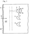
- Fig. 1 is a plan view of a wall surface 1 to which a double-jet film cooling structure according to one embodiment of the present invention is applied.
- the wall surface 1 is exposed to a high-temperature gas G flowing in a direction indicated by the arrow.
- a plurality of injection ports 2 through which a cooling medium such as air is injected into a passage GP of the high-temperature gas G are aligned in a direction (up-down direction in FIG. 1 ) substantially orthogonal to the flow direction of the high-temperature gas G.
- a cooling medium such as air
- each injection port 2 is connected to a main passage 3 formed inside a wall 10 having the wall surface 1 as an upper surface, branch passages 4, 5 branching from the main passage 3, and communication passages 6, 7 which allow the main passage 3 to communicate with the branch passages 4, 5.
- the injection port 2 is formed of outlets 3a, 4a, 5a, 6a, and 7a of these passages 3 to 7.
- the main passage 3 is parallel with the flow direction of the high-temperature gas G in a plan view as viewed from the direction orthogonal to the wall surface 1.
- the branch passages 4, 5 branch from the main passage 3 in a transverse direction (up-down direction of Fig. 1 ) with respect to the flow direction of the high-temperature gas G.
- the communication passages 6, 7 allow the main passage 3 to communicate with the branch passages 4, 5, respectively, in the transverse direction (up-down direction in Fig. 1 ) with respect to the flow direction.
- These passages 3 to 7 form a collective passage having a plane-symmetrical shape with respect to an orthogonal plane VP which includes an axis C3 of the main passage 3 and is orthogonal to the wall surface 1.
- the passages 3 to 7 are formed by, for example, electric-discharge machining.
- the branch passages 4, 5 branch from a common branch point P on the axis C3 of the main passage 3.
- a branching angle of each of the branch passages 4, 5 as viewed from the direction orthogonal to the wall surface 1, i.e., a branching angle ⁇ shown in Fig. 2 is preferably within a range of 5 to 30 degrees, and more preferably, 10 to 20 degrees.
- Injection directions A, B of cooling medium components CL4, CL5 injected from branch passage outlets 4a, 5a do not coincide with axes C4, C5 of the branch passages 4, 5, and depend on the shape of the injection port 2 as described below.
- the branch passages 4, 5 are set to be oriented in different directions from each other on a plane along the wall surface 1, i.e., in a plan view as viewed from the direction orthogonal to the wall surface 1.
- the cooling medium components CL4, CL5 passing through the branch passages 4, 5 are injected out in directions apart from each other.
- the injection directions A, B are oriented in opposite directions from each other with respect to the flow direction of the high-temperature gas G in the plan view, and transverse injection angles ⁇ , along the wall surface 1, of the injection directions A, B with respect to the flow direction of the high-temperature gas G are set to the same value.
- the branch passage outlets 4a, 5a included in the injection port 2 have oval shapes whose major axes are the axes C4, C5 of the branch passages 4, 5.
- a front end 2f of the injection port 2 i.e., an intersection point 2f of the axis C3 of the main passage 3 and an front edge of the injection port 2 in the plan view of Fig. 2
- the transverse injection angle ⁇ is defined as an angle (angle along the wall surface 1) which is formed between a straight line that passes the front end 2f of the injection port 2 and a center O1(O2) of the branch passage outlet 4a (5a), and the axis C3.
- a portion CL3 of the cooling medium CL introduced to the main passage 3 flows into a portion 30 of the main passage 3 downstream of the branch point P (hereinafter referred to as "main passage downstream portion"), and is injected from the outlet 3a in the direction along the axis C3.
- Each of the main passage 3 and the branch passages 4, 5 is in the form of a straight round hole having a constant inner diameter D.
- Each of the communication passages 6, 7 includes a group of straight passages each passing the branch point P, and is formed of an envelope surface obtained by continuously arranging the passages.
- Each of the passages forming the passage group has a transverse cross section having the same constant inner diameter D as the main passage 3 and the branch passages 4, 5. Therefore, as shown in Fig. 3 viewed from the direction of the axis C3 of the main passage 3, the communication passage outlets 6a, 7a draw smooth curves connecting the main passage outlet 3a with the branch passage outlets 4a, 5a.
- the round holes forming the passages 3 to 7 are shown by alternate long and two short dashes lines in a right part of Fig. 2 .
- the main passage 3 formed penetrating through the wall 10 includes an introduction opening 3b which is opened at an inner surface 11 of the wall 10 and introduces the cooling medium CL such as air from the inside of the wall 10 into the main passage 3.
- the axis C3 of the main passage 3 is inclined to the downstream side of the flow direction of the high-temperature gas G, from the introduction opening 3b toward the outlet 3a at the wall surface 1 as an outer surface.
- the axes C4, C5 of the branch passages 4, 5 are inclined to the downstream side of the flow direction of the high-temperature gas G, from the branch point P toward the outlets 4a, 5a.
- the cooling medium components CL3 to CL5 are injected from the outlets 3a to 5a to the high-temperature gas passage GP, along the axes C3 to C5 of the main passage 3 and the branch passages 4, 5. Also, portions CL6, CL7 of the cooling medium are injected from the outlets 6a, 7a of the communication passages 6, 7.
- a main longitudinal angle ⁇ 1 formed between the axis C3 and the wall surface 1 shown in Fig. 4 is greater than a branch longitudinal angle ⁇ 2 formed between the axis C4 (C5) of the branch passage 4 (5) and the wall surface 1.
- the branch longitudinal angles ⁇ 2, ⁇ 2 of the branch passages 4, 5 are the same.
- the branch longitudinal angle ⁇ 2 is accurately represented in Fig. 5 which is a perspective view, and is an angle formed between the axis C4 (C5) of the branch passage 4 (5) and a line passing a virtual point P1 on the wall surface 1 immediately above the branch point P and the center O1 (02) of the branch passage outlet 4a (5a).
- the main passage 3 and the branch passages 4, 5 are inclined with respect to the wall surface 1, and further, the branch passages 4, 5 are inclined in the transverse direction with respect to the main passage 3. Therefore, all the main passage outlet 3a and the branch passage outlets 4a, 5a included in the injection port 2 shown in Fig. 2 are oval in shape.
- the branch passage outlets 4a, 5a are positioned rearward relative to the main passage outlet 3a, i.e., on the downstream side in the flow of the high-temperature gas G.
- each of the communication passage outlets 6a, 7 a is a straight line having a width S. Since the branch passages 4, 5 are geometrically clearly separated by the flat surfaces 16b, 17b, separation of the cooling medium components CL4, CL5 injected from the branch passages 4, 5 is promoted.
- the cooling medium components CL4, CL5 injected from the branch passage outlets 4a, 5a of the injection port 2 influence each other such that each of the cooling medium components CL4, CL5 pushes the other against the wall surface 1.
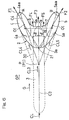
- This situation will be described with reference to Figs. 6 and 7 .
- a portion of the cooling medium CL introduced to the main passage 3 flows into the branch passages 4, 5.
- Greater portions of the cooling medium flowing in the branch passages 4, 5, as the branch passage components CL4, CL5 are injected out, at the transverse injection angle ⁇ , as straight cooling medium flows F1, F2, from the branch passage outlets 4a, 5a to the high-temperature gas passage GP.
- the straight cooling medium flows F1, F2 injected from the portions of the branch passage outlets 4a, 5a that are positioned rearward relative to the main passage outlet 3a are formed as flows having high directivities.
- Fig. 7 shows a transverse cross section of the high-temperature gas passage GP, which is orthogonal to the flow direction of the high-temperature gas G.
- the main separated flow F3 and the sub separated flows F4, F5 from the main passage downstream portion 30 and the communication passages 6, 7 allow the straight cooling medium flows F1, F2 having high directivities, from the branch passages 4, 5, to be separated from each other in the direction parallel to the wall surface 1.
- a forceful low-pressure region 11 is generated between the straight cooling medium flows F1, F2.
- the forceful low-pressure region 11 causes flows oriented toward the wall surface 1, in inner portions of the straight cooling medium flows F1, F2, i.e., in portions thereof facing each other.
- swirl flows V1, V2 oriented in opposite directions are generated in the straight cooling medium flows F1, F2 such that the swirl flows V1, V2 inwardly swirl the cooling medium C toward the wall surface 1.
- the swirl flows V1, V2 act to push the straight cooling medium flows F1, F2, respectively, against the wall surface 1.
- the swirl flows V1, V2 are formed to push the cooling medium C against the wall surface 1.
- the two branch passage outlets 4a, 5a shown in Fig. 6 need to be apart from each other at a suitable distance.
- the branch passage outlets 4a, 5a in the injection port 2 facing the wall surface 1 have substantially oval shapes having major axes along the axes C4, C5 of the branch passages 4, 5.
- a distance W between the centers O1, O2 of the pair of branch passage outlets 4a, 5a along the wall surface 1 is preferably within a range of 1.0D to 5.0D, and more preferably within a range of 1.5D to 4.0D, with respect to the above-mentioned constant inner diameter D.
- the transverse injection angle ⁇ formed between the injection direction A (B) from the branch passage 4 (5) and the flow direction of the high-temperature gas G is preferably within a range of 10 to 45 degrees.
- the transverse injection angle ⁇ is preferably within a range of 20 to 40 degrees, and more preferably within a range of 25 to 35 degrees. If the transverse injection angle ⁇ is less than the above range, separation of the swirl flows V1, V2 becomes difficult. If the angle ⁇ exceeds the above range, straightness of the straight cooling medium flows F1, F2 becomes insufficient, and the swirl flows V1, V2 having a desired force cannot be obtained.
- the transverse injection angles ⁇ , ⁇ formed between the injection directions A, B from the branch passages 4, 5 and the flow direction of the high-temperature gas G, respectively, may be different from each other.
- the axis C3 of the main passage 3 is not along the flow direction of the high-temperature gas G
- the injection directions A, B from the branch passages 4, 5 are set to be symmetrical with respect to the axis C3 of the main passage 3
- the transverse injection angle ⁇ with respect to the high-temperature gas G differs between the branch passages 4, 5.
- the main longitudinal angle ⁇ 1 formed between the axis C3 of the main passage 3 and the wall surface 1 shown in Fig. 4 is preferably within a range of 10 to 45 degrees, and more preferably within a range of 20 to 40 degrees.
- the branch longitudinal angle ⁇ 2 formed between the branch passage 4 (5) and the wall surface 1 is preferably within a range of 5 to 40 degrees, and more preferably within a range of 10 to 35 degrees. If the main longitudinal angle ⁇ 1 and the branch longitudinal angle ⁇ 2 are less than the above ranges, the swirl flows V1, V2 shown in Fig. 7 are too close to the wall surface 1. If the angles ⁇ 1 and ⁇ 2 exceed the above ranges, the swirl flows V1, V2 are too far from the wall surface 1. In both cases, the swirl flows V1, V2 having a desired force cannot be obtained.
- a ratio Lc/H of the height of the branch point P to the height H of the main passage in the wall 10 shown in Fig. 4 is preferable within a range of 0.3 to 0.9, and more preferably within a range of 0.4 to 0.8.
- This ratio corresponds to a ratio of the length of a portion of the main passage 3 which is upstream relative to the branch point P to the entire length L of the main passage 3. If the length ratio Lc/H is less than the above range, straightness of the separated flow F3 injected from the main passage 3 shown in Fig. 6 is degraded, and the function of separating the straight flows F1, F2 from the branch passages 4, 5 is degraded. If the length ratio Lc/H exceeds the above range, the supply amounts of the cooling medium components CL4, CL5 to the branch passages 4, 5 become insufficient. Therefore, in both cases, the swirl flows V1, V2 having a desired force cannot be obtained.
- the entire length L of main passage 3 is preferably within a range of 2D to 10D in relation to the constant inner diameter D. If the entire length L is less than 2D, the directivities of the cooling medium components injected from the main passage 3 and the branch passages 4, 5 are degraded. If the entire length L exceeds 10D, passage resistance is increased.
- a method of manufacturing the above-mentioned cooling structure will be described.
- all the main passage 3, the branch passages 4, 5, and the communication passages 6, 7 are machined from the wall surface 1 side by using a cylindrical machining electrode 41 of an electric-discharge machine.
- the machining electrode 41 has a predetermined outer diameter slightly smaller than the constant inner diameter D, in order to form the passages 3 to 7 each having the constant inner diameter D.
- the main passage 3 is formed by electric-discharge machining using the machining electrode 41.
- the passages from the communication passages 6, 7 to the branch passages 4, 5 are continuously formed by performing discharging with the machining electrode being inclined with respect to the axis C3 of the main passage 3.
- the cooling medium components CL4, CL5 injected from the pair of branch passages 4, 5 are pushed against the wall surface 1 by the swirl flows V1, V2 inwardly swirled to the low-pressure region 11, and contact a wide range of the wall surface 1, thereby forming a film flow of the cooling medium CL.
- the cooling medium CL is suppressed from being separated from the wall surface 1, and the film efficiency on the wall surface 1 is enhanced.
- the wall surface 1 is effectively cooled.
- Fig. 8 is an isogram diagram of the film efficiency ⁇ f,ad obtained on the wall surface 1 when parameters including the dimensions and ratios shown in Fig. 2 and Fig. 4 are set as follows.
- the cooling medium CL injected from the injection port 2 forms a region of a film efficiency of 1.0 near its downstream side, a region of a film efficiency of 0.8 behind the region of the film efficiency of 1.0, a region of a film efficiency of 0.6 inward the region of the film efficiency of 0.8 in its width direction, a region of a film efficiency of 0.4 inward the region of the film efficiency of 0.6 in the width direction, and a region of a film efficiency of 0.2 at its outermost side, each of these regions being formed over a wide area.
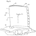
- Figs. 9 to 11 show examples in which the present invention is applied to a turbine blade of a gas turbine.
- the gas turbine includes a compressor for compressing air, a combustor which is supplied with a fuel and the compressed air from the compressor and combusts the fuel, and a turbine driven by a high-temperature and high-pressure combustion gas supplied from the combustor.
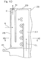
- the turbine is configured such that many rotor blades 23 are implanted in an outer peripheral portion of a turbine disk 21 shown in FIG. 9 .
- a cooling medium passage 27 having a folded shape as shown in Fig. 10 is formed inside the rotor blade 23, a cooling medium passage 27 having a folded shape as shown in Fig. 10 is formed.
- the injection ports 2 communicate with an intermediate portion of the cooling medium passage 27.
- a cooling medium CL composed of air that has been extracted from the compressor is introduced into the cooling medium passage 27 through a passage in the turbine disk 21, and injected from the injection ports 2. Thereafter, the cooling medium CL is injected into the passage GP through a jet hole 31 opened in a blade tip 29.
- the cooling medium CL injected from the injection ports 2 opened in the blade surface which is the wall surface 1 shown in FIG. 11 , forms a film flow CF of the cooling medium C on the blade surface 1, whereby the rotor blade 23 is effectively cooled.
- the number and arrangement of the plurality of injection ports 2 may be appropriately selected.
- two lines, each line being formed of a plurality of injection ports 2 aligned at equal intervals in the radial direction may be formed spaced apart from each other in the front-rear direction such that the radial positions of the injection ports 2 in the front line are shifted from the radial positions of the injection ports 2 in the rear line.
- the present invention is widely applicable to wall surfaces facing the high-temperature gas passage, such as a stator blade, an inner tube of a combustor, and the like, as well as the rotor blade of the gas turbine.
Landscapes
- Engineering & Computer Science (AREA)
- Mechanical Engineering (AREA)
- General Engineering & Computer Science (AREA)
- Physics & Mathematics (AREA)
- Thermal Sciences (AREA)
- Manufacturing & Machinery (AREA)
- Chemical & Material Sciences (AREA)
- Combustion & Propulsion (AREA)
- Fluid Mechanics (AREA)
- Turbine Rotor Nozzle Sealing (AREA)
- Electrical Discharge Machining, Electrochemical Machining, And Combined Machining (AREA)
Applications Claiming Priority (2)
| Application Number | Priority Date | Filing Date | Title |
|---|---|---|---|
| JP2013108333A JP5530001B1 (ja) | 2013-05-22 | 2013-05-22 | ダブルジェット式フイルム冷却構造とその製造方法 |
| PCT/JP2014/063517 WO2014189092A1 (fr) | 2013-05-22 | 2014-05-21 | Structure de refroidissement de film à double jet et son procédé de production |
Publications (3)
| Publication Number | Publication Date |
|---|---|
| EP3000971A1 true EP3000971A1 (fr) | 2016-03-30 |
| EP3000971A4 EP3000971A4 (fr) | 2017-03-08 |
| EP3000971B1 EP3000971B1 (fr) | 2020-04-08 |
Family
ID=51175816
Family Applications (1)
| Application Number | Title | Priority Date | Filing Date |
|---|---|---|---|
| EP14800768.5A Active EP3000971B1 (fr) | 2013-05-22 | 2014-05-21 | Structure de refroidissement par film à double jet pour une paroi et procédé de manufacture associé |
Country Status (6)
| Country | Link |
|---|---|
| US (1) | US9945233B2 (fr) |
| EP (1) | EP3000971B1 (fr) |
| JP (1) | JP5530001B1 (fr) |
| CN (1) | CN105308267B (fr) |
| CA (1) | CA2912828A1 (fr) |
| WO (1) | WO2014189092A1 (fr) |
Cited By (1)
| Publication number | Priority date | Publication date | Assignee | Title |
|---|---|---|---|---|
| EP3255248A1 (fr) * | 2016-04-14 | 2017-12-13 | General Electric Company | Composant pour un moteur à turbine |
Families Citing this family (26)
| Publication number | Priority date | Publication date | Assignee | Title |
|---|---|---|---|---|
| US11313235B2 (en) * | 2015-03-17 | 2022-04-26 | General Electric Company | Engine component with film hole |
| US10208602B2 (en) * | 2015-04-27 | 2019-02-19 | United Technologies Corporation | Asymmetric diffuser opening for film cooling holes |
| CA2933884A1 (fr) * | 2015-06-30 | 2016-12-30 | Rolls-Royce Corporation | Tuile de combustor |
| CN105298649B (zh) * | 2015-11-20 | 2017-10-03 | 清华大学 | 一种用于燃气涡轮发动机薄壁热端部件的气膜冷却孔结构 |
| US10267161B2 (en) * | 2015-12-07 | 2019-04-23 | General Electric Company | Gas turbine engine with fillet film holes |
| US10697301B2 (en) | 2017-04-07 | 2020-06-30 | General Electric Company | Turbine engine airfoil having a cooling circuit |
| EP3450682A1 (fr) | 2017-08-30 | 2019-03-06 | Siemens Aktiengesellschaft | Paroi d'un composant pour gaz chaud et composant associé |
| US10648342B2 (en) * | 2017-12-18 | 2020-05-12 | General Electric Company | Engine component with cooling hole |
| CN108843403B (zh) * | 2018-06-13 | 2022-10-25 | 中国科学院宁波材料技术与工程研究所 | 一种在基体表面产生连续气膜的方法 |
| CN108590777B (zh) * | 2018-06-13 | 2021-11-30 | 中国科学院宁波材料技术与工程研究所 | 一种基体表面连续气膜的发生结构 |
| US11359495B2 (en) | 2019-01-07 | 2022-06-14 | Rolls- Royce Corporation | Coverage cooling holes |
| CN109763868B (zh) * | 2019-03-13 | 2020-05-19 | 北京航空航天大学 | 一种新型分叉气膜孔 |
| CN111829009A (zh) * | 2020-07-10 | 2020-10-27 | 中国空气动力研究与发展中心 | 一种基于楔形体的燃料组合喷注结构 |
| CN112443361A (zh) * | 2020-11-04 | 2021-03-05 | 西北工业大学 | 一种用于涡轮叶片的凹坑逆向气膜孔结构 |
| US11674686B2 (en) * | 2021-05-11 | 2023-06-13 | Honeywell International Inc. | Coating occlusion resistant effusion cooling holes for gas turbine engine |
| US11542831B1 (en) | 2021-08-13 | 2023-01-03 | Raytheon Technologies Corporation | Energy beam positioning during formation of a cooling aperture |
| US11913119B2 (en) | 2021-08-13 | 2024-02-27 | Rtx Corporation | Forming cooling aperture(s) in a turbine engine component |
| US11732590B2 (en) | 2021-08-13 | 2023-08-22 | Raytheon Technologies Corporation | Transition section for accommodating mismatch between other sections of a cooling aperture in a turbine engine component |
| US11673200B2 (en) | 2021-08-13 | 2023-06-13 | Raytheon Technologies Corporation | Forming cooling aperture(s) using electrical discharge machining |
| US11813706B2 (en) | 2021-08-13 | 2023-11-14 | Rtx Corporation | Methods for forming cooling apertures in a turbine engine component |
| US11603769B2 (en) | 2021-08-13 | 2023-03-14 | Raytheon Technologies Corporation | Forming lined cooling aperture(s) in a turbine engine component |
| US11898465B2 (en) | 2021-08-13 | 2024-02-13 | Rtx Corporation | Forming lined cooling aperture(s) in a turbine engine component |
| US12123839B2 (en) | 2021-08-13 | 2024-10-22 | Rtx Corporation | Forming and/or inspecting cooling aperture(s) in a turbine engine component |
| WO2023211485A2 (fr) * | 2021-10-22 | 2023-11-02 | Raytheon Technologies Corporation | Élément de moteur à turbine à gaz à trous de refroidissement destiné à réduire le refoulement |
| KR102737646B1 (ko) * | 2022-05-24 | 2024-12-03 | 국립창원대학교 산학협력단 | 터빈 블레이드의 표면 막 냉각홀 구조 및 그 가공방법 |
| CN116085117A (zh) * | 2023-04-10 | 2023-05-09 | 清华大学 | 导向结构 |
Family Cites Families (19)
| Publication number | Priority date | Publication date | Assignee | Title |
|---|---|---|---|---|
| JP2001012204A (ja) * | 1999-06-30 | 2001-01-16 | Toshiba Corp | ガスタービン翼 |
| US7328580B2 (en) * | 2004-06-23 | 2008-02-12 | General Electric Company | Chevron film cooled wall |
| US20080003096A1 (en) | 2006-06-29 | 2008-01-03 | United Technologies Corporation | High coverage cooling hole shape |
| US8529193B2 (en) * | 2009-11-25 | 2013-09-10 | Honeywell International Inc. | Gas turbine engine components with improved film cooling |
| JP4954309B2 (ja) | 2010-03-24 | 2012-06-13 | 川崎重工業株式会社 | ダブルジェット式フィルム冷却構造 |
| US8905713B2 (en) * | 2010-05-28 | 2014-12-09 | General Electric Company | Articles which include chevron film cooling holes, and related processes |
| US8733111B2 (en) | 2012-02-15 | 2014-05-27 | United Technologies Corporation | Cooling hole with asymmetric diffuser |
| US9598979B2 (en) | 2012-02-15 | 2017-03-21 | United Technologies Corporation | Manufacturing methods for multi-lobed cooling holes |
| US8689568B2 (en) | 2012-02-15 | 2014-04-08 | United Technologies Corporation | Cooling hole with thermo-mechanical fatigue resistance |
| US8850828B2 (en) | 2012-02-15 | 2014-10-07 | United Technologies Corporation | Cooling hole with curved metering section |
| US8584470B2 (en) | 2012-02-15 | 2013-11-19 | United Technologies Corporation | Tri-lobed cooling hole and method of manufacture |
| US9482100B2 (en) | 2012-02-15 | 2016-11-01 | United Technologies Corporation | Multi-lobed cooling hole |
| US8763402B2 (en) | 2012-02-15 | 2014-07-01 | United Technologies Corporation | Multi-lobed cooling hole and method of manufacture |
| US8707713B2 (en) | 2012-02-15 | 2014-04-29 | United Technologies Corporation | Cooling hole with crenellation features |
| US8683813B2 (en) | 2012-02-15 | 2014-04-01 | United Technologies Corporation | Multi-lobed cooling hole and method of manufacture |
| US9273560B2 (en) | 2012-02-15 | 2016-03-01 | United Technologies Corporation | Gas turbine engine component with multi-lobed cooling hole |
| US9024226B2 (en) | 2012-02-15 | 2015-05-05 | United Technologies Corporation | EDM method for multi-lobed cooling hole |
| US9410435B2 (en) * | 2012-02-15 | 2016-08-09 | United Technologies Corporation | Gas turbine engine component with diffusive cooling hole |
| US9316104B2 (en) * | 2012-10-25 | 2016-04-19 | United Technologies Corporation | Film cooling channel array having anti-vortex properties |
-
2013
- 2013-05-22 JP JP2013108333A patent/JP5530001B1/ja active Active
-
2014
- 2014-05-21 CN CN201480029137.8A patent/CN105308267B/zh active Active
- 2014-05-21 CA CA2912828A patent/CA2912828A1/fr not_active Abandoned
- 2014-05-21 WO PCT/JP2014/063517 patent/WO2014189092A1/fr not_active Ceased
- 2014-05-21 EP EP14800768.5A patent/EP3000971B1/fr active Active
-
2015
- 2015-11-18 US US14/944,503 patent/US9945233B2/en active Active
Non-Patent Citations (1)
| Title |
|---|
| See references of WO2014189092A1 * |
Cited By (1)
| Publication number | Priority date | Publication date | Assignee | Title |
|---|---|---|---|---|
| EP3255248A1 (fr) * | 2016-04-14 | 2017-12-13 | General Electric Company | Composant pour un moteur à turbine |
Also Published As
| Publication number | Publication date |
|---|---|
| JP2014227914A (ja) | 2014-12-08 |
| US20160069192A1 (en) | 2016-03-10 |
| CN105308267A (zh) | 2016-02-03 |
| US9945233B2 (en) | 2018-04-17 |
| CA2912828A1 (fr) | 2014-11-27 |
| CN105308267B (zh) | 2017-06-13 |
| JP5530001B1 (ja) | 2014-06-25 |
| EP3000971B1 (fr) | 2020-04-08 |
| EP3000971A4 (fr) | 2017-03-08 |
| WO2014189092A1 (fr) | 2014-11-27 |
Similar Documents
| Publication | Publication Date | Title |
|---|---|---|
| US9945233B2 (en) | Double-jet film cooling structure and method for manufacturing same | |
| US9599411B2 (en) | Double-jet type film cooling structure | |
| EP3000972B1 (fr) | Structure de refroidissement d'aube de turbine | |
| US8628292B2 (en) | Eccentric chamfer at inlet of branches in a flow channel | |
| CN101675228B (zh) | 燃气轮机燃烧器 | |
| US10060265B2 (en) | Turbine blade | |
| US20100040459A1 (en) | Film cooling structure | |
| EP2792851A1 (fr) | Lame de turbine | |
| US12607419B2 (en) | Plate heat exchanger comprising profiled guide elements | |
| JP2012219702A (ja) | タービン翼 | |
| EP1788193B1 (fr) | Agencement de refroidissement par film à double jet | |
| US11708762B2 (en) | Film cooling structure and turbine blade for gas turbine engine | |
| WO2013081142A1 (fr) | Pale de turbine | |
| BR102016004205A2 (pt) | componente de motor para um motor de turbina a gás | |
| KR20140014252A (ko) | 터빈 동익 | |
| JP6659823B2 (ja) | タービンブレードの冷却配置 | |
| EP3358138A1 (fr) | Dispositif de pré-tourbillonnement pour turbine à gaz | |
| US20130236301A1 (en) | Apparatus And System For Directing Hot Gas | |
| JP2005015923A (ja) | 水噴射式織機の緯入れノズル | |
| US11028701B2 (en) | Structure for cooling turbine blade | |
| JP6583780B2 (ja) | 翼及びこれを備えるガスタービン | |
| US20180216475A1 (en) | Component for a gas turbine engine |
Legal Events
| Date | Code | Title | Description |
|---|---|---|---|
| PUAI | Public reference made under article 153(3) epc to a published international application that has entered the european phase |
Free format text: ORIGINAL CODE: 0009012 |
|
| 17P | Request for examination filed |
Effective date: 20151203 |
|
| AK | Designated contracting states |
Kind code of ref document: A1 Designated state(s): AL AT BE BG CH CY CZ DE DK EE ES FI FR GB GR HR HU IE IS IT LI LT LU LV MC MK MT NL NO PL PT RO RS SE SI SK SM TR |
|
| AX | Request for extension of the european patent |
Extension state: BA ME |
|
| DAX | Request for extension of the european patent (deleted) | ||
| A4 | Supplementary search report drawn up and despatched |
Effective date: 20170207 |
|
| RIC1 | Information provided on ipc code assigned before grant |
Ipc: F02C 7/18 20060101ALI20170201BHEP Ipc: F02C 7/00 20060101ALI20170201BHEP Ipc: F01D 5/18 20060101AFI20170201BHEP Ipc: B23H 9/10 20060101ALI20170201BHEP Ipc: F01D 9/02 20060101ALI20170201BHEP |
|
| GRAP | Despatch of communication of intention to grant a patent |
Free format text: ORIGINAL CODE: EPIDOSNIGR1 |
|
| STAA | Information on the status of an ep patent application or granted ep patent |
Free format text: STATUS: GRANT OF PATENT IS INTENDED |
|
| RIC1 | Information provided on ipc code assigned before grant |
Ipc: F01D 5/18 20060101AFI20191010BHEP Ipc: B23H 9/10 20060101ALN20191010BHEP Ipc: B23H 9/14 20060101ALI20191010BHEP |
|
| RIC1 | Information provided on ipc code assigned before grant |
Ipc: F01D 5/18 20060101AFI20191018BHEP Ipc: B23H 9/14 20060101ALI20191018BHEP Ipc: B23H 9/10 20060101ALN20191018BHEP |
|
| INTG | Intention to grant announced |
Effective date: 20191108 |
|
| GRAS | Grant fee paid |
Free format text: ORIGINAL CODE: EPIDOSNIGR3 |
|
| GRAA | (expected) grant |
Free format text: ORIGINAL CODE: 0009210 |
|
| STAA | Information on the status of an ep patent application or granted ep patent |
Free format text: STATUS: THE PATENT HAS BEEN GRANTED |
|
| AK | Designated contracting states |
Kind code of ref document: B1 Designated state(s): AL AT BE BG CH CY CZ DE DK EE ES FI FR GB GR HR HU IE IS IT LI LT LU LV MC MK MT NL NO PL PT RO RS SE SI SK SM TR |
|
| REG | Reference to a national code |
Ref country code: CH Ref legal event code: EP Ref country code: AT Ref legal event code: REF Ref document number: 1254644 Country of ref document: AT Kind code of ref document: T Effective date: 20200415 |
|
| REG | Reference to a national code |
Ref country code: IE Ref legal event code: FG4D |
|
| REG | Reference to a national code |
Ref country code: DE Ref legal event code: R096 Ref document number: 602014063572 Country of ref document: DE |
|
| REG | Reference to a national code |
Ref country code: NL Ref legal event code: MP Effective date: 20200408 |
|
| REG | Reference to a national code |
Ref country code: LT Ref legal event code: MG4D |
|
| PG25 | Lapsed in a contracting state [announced via postgrant information from national office to epo] |
Ref country code: NL Free format text: LAPSE BECAUSE OF FAILURE TO SUBMIT A TRANSLATION OF THE DESCRIPTION OR TO PAY THE FEE WITHIN THE PRESCRIBED TIME-LIMIT Effective date: 20200408 Ref country code: SE Free format text: LAPSE BECAUSE OF FAILURE TO SUBMIT A TRANSLATION OF THE DESCRIPTION OR TO PAY THE FEE WITHIN THE PRESCRIBED TIME-LIMIT Effective date: 20200408 Ref country code: NO Free format text: LAPSE BECAUSE OF FAILURE TO SUBMIT A TRANSLATION OF THE DESCRIPTION OR TO PAY THE FEE WITHIN THE PRESCRIBED TIME-LIMIT Effective date: 20200708 Ref country code: FI Free format text: LAPSE BECAUSE OF FAILURE TO SUBMIT A TRANSLATION OF THE DESCRIPTION OR TO PAY THE FEE WITHIN THE PRESCRIBED TIME-LIMIT Effective date: 20200408 Ref country code: IS Free format text: LAPSE BECAUSE OF FAILURE TO SUBMIT A TRANSLATION OF THE DESCRIPTION OR TO PAY THE FEE WITHIN THE PRESCRIBED TIME-LIMIT Effective date: 20200808 Ref country code: LT Free format text: LAPSE BECAUSE OF FAILURE TO SUBMIT A TRANSLATION OF THE DESCRIPTION OR TO PAY THE FEE WITHIN THE PRESCRIBED TIME-LIMIT Effective date: 20200408 Ref country code: GR Free format text: LAPSE BECAUSE OF FAILURE TO SUBMIT A TRANSLATION OF THE DESCRIPTION OR TO PAY THE FEE WITHIN THE PRESCRIBED TIME-LIMIT Effective date: 20200709 Ref country code: PT Free format text: LAPSE BECAUSE OF FAILURE TO SUBMIT A TRANSLATION OF THE DESCRIPTION OR TO PAY THE FEE WITHIN THE PRESCRIBED TIME-LIMIT Effective date: 20200817 |
|
| REG | Reference to a national code |
Ref country code: AT Ref legal event code: MK05 Ref document number: 1254644 Country of ref document: AT Kind code of ref document: T Effective date: 20200408 |
|
| PG25 | Lapsed in a contracting state [announced via postgrant information from national office to epo] |
Ref country code: LV Free format text: LAPSE BECAUSE OF FAILURE TO SUBMIT A TRANSLATION OF THE DESCRIPTION OR TO PAY THE FEE WITHIN THE PRESCRIBED TIME-LIMIT Effective date: 20200408 Ref country code: RS Free format text: LAPSE BECAUSE OF FAILURE TO SUBMIT A TRANSLATION OF THE DESCRIPTION OR TO PAY THE FEE WITHIN THE PRESCRIBED TIME-LIMIT Effective date: 20200408 Ref country code: BG Free format text: LAPSE BECAUSE OF FAILURE TO SUBMIT A TRANSLATION OF THE DESCRIPTION OR TO PAY THE FEE WITHIN THE PRESCRIBED TIME-LIMIT Effective date: 20200708 Ref country code: HR Free format text: LAPSE BECAUSE OF FAILURE TO SUBMIT A TRANSLATION OF THE DESCRIPTION OR TO PAY THE FEE WITHIN THE PRESCRIBED TIME-LIMIT Effective date: 20200408 |
|
| PG25 | Lapsed in a contracting state [announced via postgrant information from national office to epo] |
Ref country code: AL Free format text: LAPSE BECAUSE OF FAILURE TO SUBMIT A TRANSLATION OF THE DESCRIPTION OR TO PAY THE FEE WITHIN THE PRESCRIBED TIME-LIMIT Effective date: 20200408 |
|
| REG | Reference to a national code |
Ref country code: DE Ref legal event code: R097 Ref document number: 602014063572 Country of ref document: DE |
|
| PG25 | Lapsed in a contracting state [announced via postgrant information from national office to epo] |
Ref country code: IT Free format text: LAPSE BECAUSE OF FAILURE TO SUBMIT A TRANSLATION OF THE DESCRIPTION OR TO PAY THE FEE WITHIN THE PRESCRIBED TIME-LIMIT Effective date: 20200408 Ref country code: RO Free format text: LAPSE BECAUSE OF FAILURE TO SUBMIT A TRANSLATION OF THE DESCRIPTION OR TO PAY THE FEE WITHIN THE PRESCRIBED TIME-LIMIT Effective date: 20200408 Ref country code: CZ Free format text: LAPSE BECAUSE OF FAILURE TO SUBMIT A TRANSLATION OF THE DESCRIPTION OR TO PAY THE FEE WITHIN THE PRESCRIBED TIME-LIMIT Effective date: 20200408 Ref country code: SM Free format text: LAPSE BECAUSE OF FAILURE TO SUBMIT A TRANSLATION OF THE DESCRIPTION OR TO PAY THE FEE WITHIN THE PRESCRIBED TIME-LIMIT Effective date: 20200408 Ref country code: CH Free format text: LAPSE BECAUSE OF NON-PAYMENT OF DUE FEES Effective date: 20200531 Ref country code: AT Free format text: LAPSE BECAUSE OF FAILURE TO SUBMIT A TRANSLATION OF THE DESCRIPTION OR TO PAY THE FEE WITHIN THE PRESCRIBED TIME-LIMIT Effective date: 20200408 Ref country code: EE Free format text: LAPSE BECAUSE OF FAILURE TO SUBMIT A TRANSLATION OF THE DESCRIPTION OR TO PAY THE FEE WITHIN THE PRESCRIBED TIME-LIMIT Effective date: 20200408 Ref country code: LI Free format text: LAPSE BECAUSE OF NON-PAYMENT OF DUE FEES Effective date: 20200531 Ref country code: DK Free format text: LAPSE BECAUSE OF FAILURE TO SUBMIT A TRANSLATION OF THE DESCRIPTION OR TO PAY THE FEE WITHIN THE PRESCRIBED TIME-LIMIT Effective date: 20200408 Ref country code: ES Free format text: LAPSE BECAUSE OF FAILURE TO SUBMIT A TRANSLATION OF THE DESCRIPTION OR TO PAY THE FEE WITHIN THE PRESCRIBED TIME-LIMIT Effective date: 20200408 Ref country code: MC Free format text: LAPSE BECAUSE OF FAILURE TO SUBMIT A TRANSLATION OF THE DESCRIPTION OR TO PAY THE FEE WITHIN THE PRESCRIBED TIME-LIMIT Effective date: 20200408 |
|
| PLBE | No opposition filed within time limit |
Free format text: ORIGINAL CODE: 0009261 |
|
| STAA | Information on the status of an ep patent application or granted ep patent |
Free format text: STATUS: NO OPPOSITION FILED WITHIN TIME LIMIT |
|
| PG25 | Lapsed in a contracting state [announced via postgrant information from national office to epo] |
Ref country code: PL Free format text: LAPSE BECAUSE OF FAILURE TO SUBMIT A TRANSLATION OF THE DESCRIPTION OR TO PAY THE FEE WITHIN THE PRESCRIBED TIME-LIMIT Effective date: 20200408 Ref country code: SK Free format text: LAPSE BECAUSE OF FAILURE TO SUBMIT A TRANSLATION OF THE DESCRIPTION OR TO PAY THE FEE WITHIN THE PRESCRIBED TIME-LIMIT Effective date: 20200408 |
|
| 26N | No opposition filed |
Effective date: 20210112 |
|
| REG | Reference to a national code |
Ref country code: BE Ref legal event code: MM Effective date: 20200531 |
|
| PG25 | Lapsed in a contracting state [announced via postgrant information from national office to epo] |
Ref country code: LU Free format text: LAPSE BECAUSE OF NON-PAYMENT OF DUE FEES Effective date: 20200521 |
|
| PG25 | Lapsed in a contracting state [announced via postgrant information from national office to epo] |
Ref country code: FR Free format text: LAPSE BECAUSE OF NON-PAYMENT OF DUE FEES Effective date: 20200608 Ref country code: IE Free format text: LAPSE BECAUSE OF NON-PAYMENT OF DUE FEES Effective date: 20200521 |
|
| PG25 | Lapsed in a contracting state [announced via postgrant information from national office to epo] |
Ref country code: SI Free format text: LAPSE BECAUSE OF FAILURE TO SUBMIT A TRANSLATION OF THE DESCRIPTION OR TO PAY THE FEE WITHIN THE PRESCRIBED TIME-LIMIT Effective date: 20200408 Ref country code: BE Free format text: LAPSE BECAUSE OF NON-PAYMENT OF DUE FEES Effective date: 20200531 |
|
| PG25 | Lapsed in a contracting state [announced via postgrant information from national office to epo] |
Ref country code: TR Free format text: LAPSE BECAUSE OF FAILURE TO SUBMIT A TRANSLATION OF THE DESCRIPTION OR TO PAY THE FEE WITHIN THE PRESCRIBED TIME-LIMIT Effective date: 20200408 Ref country code: MT Free format text: LAPSE BECAUSE OF FAILURE TO SUBMIT A TRANSLATION OF THE DESCRIPTION OR TO PAY THE FEE WITHIN THE PRESCRIBED TIME-LIMIT Effective date: 20200408 Ref country code: CY Free format text: LAPSE BECAUSE OF FAILURE TO SUBMIT A TRANSLATION OF THE DESCRIPTION OR TO PAY THE FEE WITHIN THE PRESCRIBED TIME-LIMIT Effective date: 20200408 |
|
| PG25 | Lapsed in a contracting state [announced via postgrant information from national office to epo] |
Ref country code: MK Free format text: LAPSE BECAUSE OF FAILURE TO SUBMIT A TRANSLATION OF THE DESCRIPTION OR TO PAY THE FEE WITHIN THE PRESCRIBED TIME-LIMIT Effective date: 20200408 |
|
| PGFP | Annual fee paid to national office [announced via postgrant information from national office to epo] |
Ref country code: DE Payment date: 20250402 Year of fee payment: 12 |
|
| PGFP | Annual fee paid to national office [announced via postgrant information from national office to epo] |
Ref country code: GB Payment date: 20260323 Year of fee payment: 13 |