EP3006379A2 - Goulotte de transport pour un automate de preparation de commande pour les pharmacies et dispositif de transport, plateau rotatif et automate de preparation de commande pour pharmacies et procede de fonctionnement d'une goulotte de transport - Google Patents
Goulotte de transport pour un automate de preparation de commande pour les pharmacies et dispositif de transport, plateau rotatif et automate de preparation de commande pour pharmacies et procede de fonctionnement d'une goulotte de transport Download PDFInfo
- Publication number
- EP3006379A2 EP3006379A2 EP15002697.9A EP15002697A EP3006379A2 EP 3006379 A2 EP3006379 A2 EP 3006379A2 EP 15002697 A EP15002697 A EP 15002697A EP 3006379 A2 EP3006379 A2 EP 3006379A2
- Authority
- EP
- European Patent Office
- Prior art keywords
- conveyor
- trough
- conveyor trough
- turntable
- conveying direction
- Prior art date
- Legal status (The legal status is an assumption and is not a legal conclusion. Google has not performed a legal analysis and makes no representation as to the accuracy of the status listed.)
- Withdrawn
Links
- 238000000034 method Methods 0.000 title claims description 7
- 239000003814 drug Substances 0.000 description 7
- 229940079593 drug Drugs 0.000 description 6
- 230000015572 biosynthetic process Effects 0.000 description 5
- 238000005755 formation reaction Methods 0.000 description 5
- 238000012546 transfer Methods 0.000 description 5
- 230000032258 transport Effects 0.000 description 5
- 230000005484 gravity Effects 0.000 description 4
- 238000012856 packing Methods 0.000 description 4
- 238000000926 separation method Methods 0.000 description 4
- 229920005372 Plexiglas® Polymers 0.000 description 3
- 230000008901 benefit Effects 0.000 description 3
- 238000001514 detection method Methods 0.000 description 3
- 238000005259 measurement Methods 0.000 description 3
- 239000004926 polymethyl methacrylate Substances 0.000 description 3
- 238000012384 transportation and delivery Methods 0.000 description 3
- 238000011144 upstream manufacturing Methods 0.000 description 3
- 239000013590 bulk material Substances 0.000 description 2
- 230000008859 change Effects 0.000 description 2
- 238000013461 design Methods 0.000 description 2
- 230000000694 effects Effects 0.000 description 2
- 229920003023 plastic Polymers 0.000 description 2
- 230000001133 acceleration Effects 0.000 description 1
- 230000004888 barrier function Effects 0.000 description 1
- 238000011161 development Methods 0.000 description 1
- 238000006073 displacement reaction Methods 0.000 description 1
- 239000011521 glass Substances 0.000 description 1
- 238000002483 medication Methods 0.000 description 1
- 239000002184 metal Substances 0.000 description 1
- 210000002445 nipple Anatomy 0.000 description 1
- 230000010355 oscillation Effects 0.000 description 1
- 239000004033 plastic Substances 0.000 description 1
- 230000002787 reinforcement Effects 0.000 description 1
- 230000000717 retained effect Effects 0.000 description 1
- 230000003068 static effect Effects 0.000 description 1
- 238000012360 testing method Methods 0.000 description 1
- 239000012780 transparent material Substances 0.000 description 1
Images




Classifications
-
- B—PERFORMING OPERATIONS; TRANSPORTING
- B65—CONVEYING; PACKING; STORING; HANDLING THIN OR FILAMENTARY MATERIAL
- B65G—TRANSPORT OR STORAGE DEVICES, e.g. CONVEYORS FOR LOADING OR TIPPING, SHOP CONVEYOR SYSTEMS OR PNEUMATIC TUBE CONVEYORS
- B65G19/00—Conveyors comprising an impeller or a series of impellers carried by an endless traction element and arranged to move articles or materials over a supporting surface or underlying material, e.g. endless scraper conveyors
- B65G19/02—Conveyors comprising an impeller or a series of impellers carried by an endless traction element and arranged to move articles or materials over a supporting surface or underlying material, e.g. endless scraper conveyors for articles, e.g. for containers
-
- B—PERFORMING OPERATIONS; TRANSPORTING
- B65—CONVEYING; PACKING; STORING; HANDLING THIN OR FILAMENTARY MATERIAL
- B65G—TRANSPORT OR STORAGE DEVICES, e.g. CONVEYORS FOR LOADING OR TIPPING, SHOP CONVEYOR SYSTEMS OR PNEUMATIC TUBE CONVEYORS
- B65G1/00—Storing articles, individually or in orderly arrangement, in warehouses or magazines
- B65G1/02—Storage devices
- B65G1/04—Storage devices mechanical
- B65G1/137—Storage devices mechanical with arrangements or automatic control means for selecting which articles are to be removed
- B65G1/1373—Storage devices mechanical with arrangements or automatic control means for selecting which articles are to be removed for fulfilling orders in warehouses
- B65G1/1378—Storage devices mechanical with arrangements or automatic control means for selecting which articles are to be removed for fulfilling orders in warehouses the orders being assembled on fixed commissioning areas remote from the storage areas
-
- B—PERFORMING OPERATIONS; TRANSPORTING
- B65—CONVEYING; PACKING; STORING; HANDLING THIN OR FILAMENTARY MATERIAL
- B65G—TRANSPORT OR STORAGE DEVICES, e.g. CONVEYORS FOR LOADING OR TIPPING, SHOP CONVEYOR SYSTEMS OR PNEUMATIC TUBE CONVEYORS
- B65G47/00—Article or material-handling devices associated with conveyors; Methods employing such devices
- B65G47/02—Devices for feeding articles or materials to conveyors
- B65G47/04—Devices for feeding articles or materials to conveyors for feeding articles
- B65G47/06—Devices for feeding articles or materials to conveyors for feeding articles from a single group of articles arranged in orderly pattern, e.g. workpieces in magazines
- B65G47/08—Devices for feeding articles or materials to conveyors for feeding articles from a single group of articles arranged in orderly pattern, e.g. workpieces in magazines spacing or grouping the articles during feeding
-
- B—PERFORMING OPERATIONS; TRANSPORTING
- B65—CONVEYING; PACKING; STORING; HANDLING THIN OR FILAMENTARY MATERIAL
- B65G—TRANSPORT OR STORAGE DEVICES, e.g. CONVEYORS FOR LOADING OR TIPPING, SHOP CONVEYOR SYSTEMS OR PNEUMATIC TUBE CONVEYORS
- B65G47/00—Article or material-handling devices associated with conveyors; Methods employing such devices
- B65G47/02—Devices for feeding articles or materials to conveyors
- B65G47/04—Devices for feeding articles or materials to conveyors for feeding articles
- B65G47/12—Devices for feeding articles or materials to conveyors for feeding articles from disorderly-arranged article piles or from loose assemblages of articles
- B65G47/14—Devices for feeding articles or materials to conveyors for feeding articles from disorderly-arranged article piles or from loose assemblages of articles arranging or orientating the articles by mechanical or pneumatic means during feeding
- B65G47/1492—Devices for feeding articles or materials to conveyors for feeding articles from disorderly-arranged article piles or from loose assemblages of articles arranging or orientating the articles by mechanical or pneumatic means during feeding the articles being fed from a feeding conveyor
-
- B—PERFORMING OPERATIONS; TRANSPORTING
- B65—CONVEYING; PACKING; STORING; HANDLING THIN OR FILAMENTARY MATERIAL
- B65G—TRANSPORT OR STORAGE DEVICES, e.g. CONVEYORS FOR LOADING OR TIPPING, SHOP CONVEYOR SYSTEMS OR PNEUMATIC TUBE CONVEYORS
- B65G47/00—Article or material-handling devices associated with conveyors; Methods employing such devices
- B65G47/52—Devices for transferring articles or materials between conveyors i.e. discharging or feeding devices
- B65G47/68—Devices for transferring articles or materials between conveyors i.e. discharging or feeding devices adapted to receive articles arriving in one layer from one conveyor lane and to transfer them in individual layers to more than one conveyor lane or to one broader conveyor lane, or vice versa, e.g. combining the flows of articles conveyed by more than one conveyor
-
- B—PERFORMING OPERATIONS; TRANSPORTING
- B65—CONVEYING; PACKING; STORING; HANDLING THIN OR FILAMENTARY MATERIAL
- B65G—TRANSPORT OR STORAGE DEVICES, e.g. CONVEYORS FOR LOADING OR TIPPING, SHOP CONVEYOR SYSTEMS OR PNEUMATIC TUBE CONVEYORS
- B65G2201/00—Indexing codes relating to handling devices, e.g. conveyors, characterised by the type of product or load being conveyed or handled
- B65G2201/02—Articles
-
- B—PERFORMING OPERATIONS; TRANSPORTING
- B65—CONVEYING; PACKING; STORING; HANDLING THIN OR FILAMENTARY MATERIAL
- B65G—TRANSPORT OR STORAGE DEVICES, e.g. CONVEYORS FOR LOADING OR TIPPING, SHOP CONVEYOR SYSTEMS OR PNEUMATIC TUBE CONVEYORS
- B65G2203/00—Indexing code relating to control or detection of the articles or the load carriers during conveying
- B65G2203/02—Control or detection
- B65G2203/0208—Control or detection relating to the transported articles
- B65G2203/0233—Position of the article
-
- B—PERFORMING OPERATIONS; TRANSPORTING
- B65—CONVEYING; PACKING; STORING; HANDLING THIN OR FILAMENTARY MATERIAL
- B65G—TRANSPORT OR STORAGE DEVICES, e.g. CONVEYORS FOR LOADING OR TIPPING, SHOP CONVEYOR SYSTEMS OR PNEUMATIC TUBE CONVEYORS
- B65G2207/00—Indexing codes relating to constructional details, configuration and additional features of a handling device, e.g. Conveyors
- B65G2207/14—Combination of conveyors
Definitions
- the invention relates to a conveyor trough for a picking machine for pharmacies and conveyor, turntable and picking machine for pharmacies and a method for operating a conveyor.
- pharmacies that store medicines on shelves and outsource them on request. They usually consist of shelves for storing the medication and at least one movable storage and retrieval unit, which stores the medications on the shelves with a manipulator and removes them again and delivers them to dispensaries.
- the medicine box (-dose, -flasche, -tube), hereinafter also referred to as "general cargo"
- general cargo For storage, the medicine box (-dose, -flasche, -tube), hereinafter also referred to as "general cargo", must be clearly identified (eg by reading the printed barcode) and the picking machine be presented so that the built-in stacker crane the individual items grab and store in the warehouse.
- intermediate buffer such as a conveyor belt, which promotes the article of a support point in the access area of the storage and retrieval device or a transfer gripper, which deposits the article on trays within the machine from an outdoor conveyor, of which they Storage and retrieval unit picks up.
- it is provided by at least one closed by shutter / by a door, etc. shelf area, in which the user puts the article.
- the need to individually access an article involves grasping desired group formations. Even if 2 or more items are grabbed at the same time, the device controller will need some information as to what they are and they must be oriented and laid out the way they can be further processed. A loose, indefinite group of articles, which may somehow lie one above the other or against each other, can not be accessed by the stacker crane of the picking machine.
- the medicines are delivered by the wholesaler as a loose bulk collection in containers.
- the items now have to be taken out of the container one at a time, identified with the aid of a barcode scanner (or the identity has to be communicated to the device controller in other ways) and stored individually in the buffer.
- most pharmacists enter the expiration date printed on the packs so that they have a clear overview of the expiration date of each item.
- the vending machine can first offload the oldest one. It may possibly product that is about to expire, outsourced and returned, or it can expire expired items targeted.
- Increasing the buffer is usually expensive (e.g., 2nd conveyor), but in any case, it is at the expense of capacity (the second tape removes significant storage space in the interior).
- Staggered packs are identified by the leaping edges. Packages that have their edges congruent next to each other or behind each other, can not be distinguished. This is not readily possible on the basis of the pattern. So there are packs that are deep dark blue on one part of the pack and completely white in the other half. The dividing line running across the pack is recognized as a packing line by a vision system. To avoid this, all medicines would have to be taught in with the views of their different pages. In Germany, about 180,000 drugs are on offer, with 6 sides of a cuboid. For marketing reasons, manufacturers often change the design of a pack.
- the size measurement is not reliable because tightly packed packs can not be measured as individual packs. Even if a package is determined correctly, only 2 edge lengths can be determined. The height of the package must be recognized from a different angle, which is not readily possible if several packages are present. (e.g., mutual occlusion).
- the invention was based on the object to improve the separation of the piece goods and / or the recognition of characteristics of the piece goods.
- a conveyor chute for a picking machine for pharmacies which extends in a conveying direction.
- the conveyor trough according to the invention is limited by two gutter boundary walls. These extend in particular preferably along the entire extension of the conveyor trough in the conveying direction. However, it is also conceivable that a special opening geometry, for example a widening, is created at the end of the conveyor trough for the output of the piece goods conveyed along the conveyor trough. It can be selected designs of the conveyor trough, in which the piece goods to be conveyed is brought into a receiving area in the conveyor trough, for example, thrown into this or slips along a gutter boundary wall in this. From this receiving position extend in a preferred embodiment, the gutter boundary walls substantially to the end of the conveyor trough, where the subsidized cargo can be delivered to another assembly of the order picking machine.
- the conveyor trough can be designed differently than with gutter boundary walls.
- the conveyor trough here can be narrowed or closed to avoid falling out of tumbling tumbling into the conveyor trough piece goods.
- two channel boundary walls are provided, the surfaces of which do not run parallel to one another.
- the line of the surface runs in a cross-sectional plane that is perpendicular to the conveying direction and includes the vertical, not a horizontal and non-vertical line. Movements of the piece goods to be conveyed perpendicular to the surface of the gutter boundary wall can be avoided with the channel boundary wall extending in this way.
- the surfaces of the groove boundary walls forming the conveyor trough are at an angle of 90 ° or more, in particular preferably more than 90 ° to each other.
- An arrangement of 90 ° to each other causes in a particularly preferred embodiment that a block-shaped piece goods with a first boundary wall on a first groove boundary wall and a further boundary wall may rest against a second groove boundary wall, in particular with two boundary walls can abut flat against the respective groove boundary wall.
- the cargo is well in the conveyor trough.
- such an arrangement can also lead to jamming of the piece goods.
- the groove boundary walls are at an angle of more than 90 °, more preferably at an angle of more than 100 ° to each other.
- the channel boundary walls should also form a groove with one another so that the surfaces of the channel boundary walls forming the conveyor channel are preferably at an angle of less than 150 °, more preferably less than 140 °, and most preferably less than 120 °.
- the respective surface profile in a cross-sectional plane which runs perpendicular to the conveying direction and which includes the vertical, respectively does not extend horizontally and not vertically.
- the channel boundary walls are in particular V-shaped, in particular forming an enclosed angle of 90 °, in particular preferably more than 90 °, between them.
- the parcel is held by gravity well in the bottom of the conveyor trough, in particular preferably sets itself by gravity, a receiving position in which rest in a cuboid cargo two adjacent boundary walls areally assigned to each Rinnenbegrenzungsriossessionn.
- the gutter boundary walls have equal sized surfaces.
- a groove boundary wall in a direction perpendicular to the conveying direction shorter than the opposite gutter boundary wall.
- an angled surface section may follow the shorter groove wall defining the wall. This may in particular preferably be formed horizontally or is more horizontal than the gutter boundary wall to which it is adjacent.
- This surface section can be used to push piece goods in the conveyor trough.
- the piece goods lies on the surface portion and is moved by suitable means on this surface portion, which are understood by suitable means including those where lying on the surface portion piece goods is moved into the conveyor trough, because it by further piece goods, with a conveyor belt the surface portion is introduced, is moved into the conveyor trough.
- the opposing, larger running gutter boundary wall can prevent skipping goods being moved into the conveying gutter.
- one, in particular both gutter boundary walls are equipped with the formation of the conveyor trough, flat surfaces.
- the gutter boundary wall is made of a metal sheet or of a plastic.
- the above description of the invention has been described in particular with reference to the formation of the conveyor trough serving surface of the respective gutter boundary wall. This is to indicate that also more educated bodies, and in particular bodies with changing three-dimensional geometries, are used in order to provide with one or more of their surfaces a surface of a gutter boundary wall serving to form the conveyor trough.
- the conveyor trough according to the invention can be made in one piece in particular preferably.
- At least one of the groove boundary walls, the one surface of the groove boundary wall is formed by the surface of a conveyor belt.
- the direction of movement of the conveyor belt is substantially identical to the conveying direction.
- the conveyor belt can be moved both in the conveying direction and in the opposite direction to the conveying direction.
- this embodiment is combined with the embodiment described in claim 4, according to which the conveyor trough a partially along the conveying direction movable Schubklotz or gripper identifies, in particular preferred according to the development according to claim 5 by a bottom of the conveyor trough extending in the conveying direction slot in the gutter interior protrudes.
- a kind of shaking can be exerted on the piece goods or on a plurality of piece goods located in the conveyor channel during jerky operation of the conveyor belt, which is conducive to the positioning and / or separation of the piece goods.
- thrust block or gripper by speed differences in the movement of the thrust block or gripper and the conveyor belt to counter-movements (thrust block or gripper moves in one direction, conveyor belt moves in the opposite direction) advantageous effects be achieved. If, for example, the conveyor belt moves more slowly or in the opposite direction to the thrust block or gripper, it can impose a different movement, for example on one superimposed piece of goods, than the other, lower, one of the thrust block or gripper. For example, the upper piece goods then moves slower (is slowed down by the conveyor belt in its movement in the conveying direction) or the upper piece goods even moves in opposite directions to the conveying direction. This can be useful for separating the piece goods in the conveyor trough.
- Embodiments are also conceivable in which the or one of the surfaces are not flat. So bulky courses are conceivable, which can offer particular advantages if primarily bottles are to be stored as general cargo.
- the planes in which the planar surface of the two groove boundary walls are arranged intersect in the region of the bottom of the conveyor trough.
- the surfaces of the gutter boundary walls do not abut one another directly in the bottom of the conveyor trough.
- a slot running at least partially along the bottom of the conveyor trough is provided.
- the conveyor trough has an at least partially movable along the conveying direction thrust block or gripper.
- the thrust block can also be designed as a pin.
- the gripper can also be designed as a hook, which seizes the cargo to be conveyed end side and pulls behind.
- suction cups or grippers with the piece goods on opposite boundary walls of the piece goods attacking elements particularly preferably pins, conceivable.
- the thrust block which can be moved along the conveying direction projects out of a slot extending in the conveying direction in the conveying direction of the bottom.
- one or more thrust blocks are disposed on a revolving chain disposed beneath the conveyor trough, a circumferential strand or belt or the like.
- the length of this element, with which the thrust block is connected is slightly longer between the respective deflection points than the way the piece goods pass through in the conveyor chute from its expected receiving position to a dispensing position at the end of the conveyor chute.
- the thrust block as seen in the direction of conveyance, already protrudes beyond the groove beyond the position assumed by the piece goods in the receiving position. It can thus be ensured that the thrust block grips the piece goods to be conveyed along the conveyor channel well.
- the push block or the gripper is moved forward and backward in the conveying direction. This can be achieved for example by a correspondingly moving chain or a correspondingly moving belt or the like or by a drive cylinder.
- the thrust block has an elongated shape and extends with its longitudinal extension, in particular preferably perpendicular to the conveying direction.
- the thrust block in a plane which is perpendicular to the longitudinal extent, a square, rectangular or more preferably triangular cross-sectional shape.
- the cross-sectional shape of the thrust block over a portion of its longitudinal extension, in particular over the part of its longitudinal extent, which projects into the conveyor trough remains the same.
- the size of the cross section may change while maintaining the cross sectional shape, the thrust block be designed, for example, tapering towards its free end.
- a base of the triangle points forwards, in the conveying direction and has a tip towards the rear, opposite to the conveying direction.
- a thrust block executed in this way can push the cargo well during a forward movement and push objects from the bottom of the conveyor to the side during a backward movement.
- the thrust block may be elongated in the conveying direction in a preferred embodiment and have a slope which descends from a higher, rearward in the conveying direction level, against the conveying direction in the direction of the bottom of the conveyor trough, and particularly preferably up to the bottom of the conveyor trough is executed.
- Such a configuration makes it possible, in the case of a backward movement of the thrust block against the conveying direction, to lift objects, in particular piece goods, behind the thrust block in the conveying direction, such as in the manner of a wedge or plow in the direction away from the bottom of the conveying channel, and particularly preferably over the slope relative to Slide the front of the push block forward until the cargo drops down again in front of the push block.
- the thrust block may have a protruding in the conveying direction over a main body of the thrust block nose.
- the thrust block undergoes an extension in the conveying direction, which is greater than the main body.
- the main body is driven for movement of the thrust block, for example via a chain, a belt or a drive cylinder and the movement span of the thrust block is limited by this drive, for example, just before the end of the conveyor trough ends or with the end of the conveyor trough ends, the provision of a nose can serve to improve the transfer of the piece goods from the conveyor trough to the next succeeding module.
- a piece goods slips along the surface of a trough boundary wall due to gravity until the article arrives in its receiving position in the bottom of the trough.
- the piece goods with two adjacent forming an edge boundary walls on a respective boundary wall associated gutter boundary wall.
- the cuboid cargo is in good the conveyor trough held.
- the opposite to the conveying direction behind the receiving position of a provided in the bottom of the conveyor slot slot thrust block is brought by driving a chain to which it is fixed to the bulk material and pushes this in the conveying direction along the conveyor trough until the bulk material the conveyor trough at one Exit leaves, for example, falls out of the conveyor trough.
- a vibrator device which can set at least one groove boundary wall, in particular preferably only briefly (a few milliseconds or a few seconds) into oscillation.
- the vibrating device can also be designed as a knocking device, which can tap on a gutter boundary wall.
- the vibrator can be used to solve a jammed in the conveyor chute so that it slides on the bottom of the conveyor chute or to solve each other jammed cargo in the conveyor trough from each other so that they move further towards the bottom of the conveyor trough ,
- the conveyor trough has sensors that can detect the presence of a piece goods at a certain point of the conveyor trough and / or the passage of a piece goods at a certain point of the conveyor trough, for example by means of a light barrier.
- sensors can be used to assist the control of components of the conveyor according to the invention, for example, to control the movement of a thrust block or gripper provided in a preferred embodiment or, for example, to control a vibrator device provided according to a preferred embodiment.
- a conveying device for a picking machine for pharmacies
- two or more conveyor channels according to the invention are provided, wherein the conveying directions of the conveyor channels are oriented differently.
- the second conveyor trough is arranged adjacent to the end of the first conveyor trough so that piece goods conveyed out of the end of the first conveyor trough are transferred into the second conveyor trough, in particular fall into the second conveyor trough.
- Such an arrangement of two conveyor channels according to the invention has the advantage that in the direction perpendicular to the conveying direction of the first conveyor trough stacked piece goods falls into the second conveyor trough running at an angle to the first conveyor trough and comes to rest there next to one another.
- the conveying directions of the two conveyor troughs at an angle of 90 ° to each other. But there are also other angles conceivable, for example, 45 °, 60 °, 70 ° or even more than 90 °, for example, 100 °, 120 °, 145 °.
- the bottom of the first groove is arranged higher than the bottom of the second conveyor trough.
- the respective conveying direction of a conveyor trough runs horizontally.
- the conveying direction of the conveying trough does not run horizontally and the piece goods slide, for example, in the manner of a chute along the conveying trough, ie the conveying device points downward from the receiving position of the piece goods at an angle to the horizontal.
- a conveying direction running at an angle to the horizontal can facilitate the conveyance of the piece goods through an optionally present pushing block or gripper.
- the turntable according to the invention for a picking machine for pharmacies has a plate rotatably driven about an axis of rotation plate whose intended for receiving piece goods surface is formed by the surface of at least two plate elements.
- the one plate element can pivot relative to the other plate element about a pivot axis which does not run parallel to the axis of rotation and does not correspond to the axis of rotation.
- a conveyor trough according to the invention can be formed when the two plate elements are pivoted about the pivot axis so that the then formed by their surfaces surfaces of groove boundary walls do not run parallel to each other or in the same plane.
- the pivot axis corresponds to the conveying direction of the conveying channel formed by the turntable according to the invention.
- the pivot axis may extend horizontally in a first position. By raising one or both of the plate elements outside the center of gravity of the surface intended for receiving piece goods, the pivot axis can be tilted out of the horizontal so that piece goods lying on the turntable can slide off the turntable. It can be determined by rotation of the turntable before tilting the pivot axis, the direction in which the cargo is to slip from the turntable.
- the plate elements are circular arc elements, in particular those with an included angle of 180 °, executed. In an alternative embodiment, the plate elements are rectangular.
- both plate elements are arranged in the horizontal and then lifted by suitable lifting elements, the one plate element upwardly from the horizontal, while by retraction of the other lifting element the second plate member is allowed to pivot down from the horizontal.
- a chute is formed, along which the piece goods located on the turntable can slide.
- the turntable according to the invention has a lifting element which can lift a plate element.
- a lifting element may be formed, for example, pin-like.
- the lifting element can be brought from below to the plate element and spend the plate member from the horizontal in an inclined position.
- a lifting element is provided for a plate element.
- at least one plate element can be changed in its relative position to the other plate element.
- two plate elements are provided, each plate element is associated with a lifting element.
- a plurality of lifting elements are associated with a plate element.
- each of a lifting element associated with a plate element is arranged eccentrically, in particular preferably not arranged on the line running perpendicular to the pivot axis and through the centroid of the surface formed by the surfaces of the two plate elements together.
- the plate elements are hinged together.
- the allowed by the articulated connection pivot angle between the plate elements is greater than 180 °.
- a limiter which limits pivoting of the plate elements relative to each other in a pivoting direction. For example, it may be provided that although the plate elements can be pivoted toward each other to form a conveyor trough, the flat position in which the surfaces of the two plate elements located in the same plane for receiving piece goods lie (even if they are swung out of the horizontal is) can not continue to pivot, so can not assume any ridge-like arrangements.
- the conveyor trough according to the invention, the conveyor device according to the invention and the turntable according to the invention are used in particular for picking machines for pharmacies. It has been found that the piece goods handled in picking machines for pharmacies can be handled particularly well with the articles according to the invention.
- the order-picking machine according to the invention for pharmacies has a conveyor trough according to the invention, a conveyor device according to the invention and / or a turntable according to the invention.
- the picking machine according to the invention provides a lift, with which the turntable can be moved within the order picking machine from a receiving position to a dispensing position.
- the picking machine according to the invention can also have an additional lift to the turntable. This can be arranged in a preferred embodiment next to the turntable, so that by tilting one or more plate elements of the turntable, the cargo can slide from the turntable on a conveyor platform of the lift.
- grippers or pushers that push or lift the cargo from the turntable on a conveyor platform of the lift.
- the conveyor platform of the lift can be moved in a preferred embodiment in two dispensing positions.
- the conveying platform of the preferred embodiment can be raised to a dispensing position, in which it transfers the piece goods lying on it to a conveying device, which returns the piece goods back into the circulation, for example, conveys them again to the conveyor.
- a second delivery position is provided, in which the conveyor platform of the lift offers the piece goods, for example, a manipulator of a storage device, which receives the piece goods from the conveyor platform and stored in a shelving system of the order picking machine. This can also be done by the conveying platform in the second delivery position transferring the piece goods to a transfer platform from which the manipulator receives and stores the piece goods.
- the turntable on a carriage with which the plate elements can be moved This allows the plate elements after receiving a piece goods from an adjacent module, for example an upstream conveyor trough are moved to provide more space for pivoting a plate member or the plate elements.
- the turntable is arranged at the end of a conveyor trough, particularly preferably a conveyor trough according to the invention, in particular preferably at the end of a conveyor device according to the invention.
- this position of the turntable is considered a receiving position, because the emerging from the conveyor trough piece goods is pushed onto the turntable, particularly preferably falls on the turntable.
- the turntable can be moved to a dispensing position.
- the turntable can move the piece goods, for example, back into a bunker newly delivered cargo or in a junk device, if it was determined that the cargo should not be stored on the turntable.
- the dispensing position may be a position in which the turntable emits the piece goods lying on it to a manipulator, which stores the piece goods in the order picking machine.
- the lift along its stroke is limited by a tube in which the turntable can be moved. This can prevent that general cargo falls during the transport of the turntable through the lift of the turntable.
- the plate elements of the turntable during movement through the lift in a conveyor trough-like shape, particularly preferably in a V-shape, tilted. As a result, the cargo is also kept well on the turntable.
- the picking machine according to the invention has at least one camera which can detect a piece goods arranged on the turntable.
- two cameras are arranged, with a camera preferably being directed from below and a camera from above onto the turntable, in particular preferably one or both cameras being arranged with a receiving direction which are at an angle to the vertical.
- three cameras can also be provided. These can in particular be oriented such that a first camera can store the piece goods lying on the turntable from above, a second camera can take the piece goods lying on the turntable from the side and a third camera can pick up the goods lying on the turntable from below. This can also be done by providing mirrors.
- the product lying on the turntable from the bottom receiving camera is not arranged below the turntable, but laterally.
- An arranged below the turntable mirror allows the laterally arranged camera then take the lying on the turntable piece goods from below when the turntable at least partially made of glass, particularly preferably Plexiglas or a transparent Plastic is made.
- the lateral arrangement of the camera makes it possible to use the space below the turntable for drives of the turntable.
- sensors for the distance measurement are provided in the region of the turntable. From the knowledge of the distance of the sensor relative to the turntable, the sensor can determine the dimension of the piece goods in a piece goods lying on the turntable.
- sensors are provided in the region of the turntable for the detection of transponders attached to the piece goods, for example for the detection of RFID chips.
- a picking machine has a rectangular piece goods which abuts with a first boundary wall on a gutter boundary wall and with a further boundary wall on a further gutter boundary wall of the conveyor trough according to the invention or on the plate elements of the turntable, particularly preferably with two boundary walls flat against the respective gutter boundary wall. This ensures that the cargo is well kept in the conveyor trough or on the turntable according to the invention.
- At least one plate element made of a transparent material, particularly preferably made of Plexiglas, made.
- An inventive method for operating a conveyor trough according to the invention with at least one partially movable along the conveying direction thrust block or gripper provides that the thrust block or the gripper is moved in the conveying direction, thereby moving a pack or group of packs along the conveying direction, wherein the thrust block or the gripper is stopped when a sensor detects that a package is moving beyond the end of the conveyor trough and leaves the conveyor trough.
- the stopping of the pusher block or of the gripper causes a group of packages, which lie one behind the other in the conveying direction, to be separated.
- the push block or the gripper is moved further in the conveying direction after stopping, and in particular preferably after the lapse of a predetermined time. If it is detected by means of a sensor that, despite the further method of the thrust block, or of the gripper, no further packing is moved out beyond the end of the conveyor, there is an operating state in which the thrust block or the gripper is only a single pack along the conveyor channel has moved. However, if the sensor recognizes that a further packing moves beyond the end of the conveyor trough and leaves the conveyor trough, the push block or the gripper is again stopped in a particularly preferred embodiment.
- a plurality of sensors are provided in the region of the end of the conveyor trough, for example a first sensor which checks whether a packing moves beyond the end of the conveyor trough and leaves the conveyor trough, and a second, somewhat further away from sensor arranged at the end of the conveying direction, which can detect whether a package remains in the conveyor trough, although the first sensor detects that a package moves beyond the end of the trough and leaves the conveyor trough.
- the position of the pusher block or the gripper can be determined when it is stopped. If packages of a standard size are conveyed, then the information relative to the end of the conveying direction can be derived from the relative position of the stopped pushing block or of the stopped gripper as to whether a group of packages has been moved along the conveying channel or if only a single package along the conveying channel was moved.
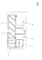
- the order picking machine 1 according to the invention comprises a conveyor belt 2, a conveyor device 5 according to the invention consisting of two conveyor chutes 3, 4 according to the invention. Likewise, the picking machine 1 according to the invention on a turntable 6 according to the invention.
- the band is designed with oblique ribs 19 and not with transverse ribs, as for example DE 10 2004 012 133 B4 are known.
- a large package no longer forms a transport wall for a stack of small packages, but through the inclined surface, the packages slip laterally and fall at least in those cases where the large package does not rest against a bunker wall (not provided in the present embodiment) as desired behind a large pack.
- Fig. 3 shows that the conveyor trough according to the invention 3 channel boundary walls 7, 8, the surfaces 9, 10 are not parallel to each other.
- the respective surface profile in a cross-sectional plane, which is perpendicular to the conveying direction A and includes the vertical, each representing line is not horizontal and also not vertical.
- the formation of the conveyor trough 3 serving surfaces 9, 10 of the channel boundary walls are arranged at an angle of 90 ° to each other.
- the surfaces 9, 10 of the gutter boundary walls 7, 8 are flat. The planes in which the flat surfaces 9, 10 extend, intersect in the region of the bottom of the conveyor trough 3.
- a slot 11 is provided through which a thrust block in the form of a pin 12 engages.
- a circulating chain is arranged below the conveyor trough 3. At this, the pin 12 is attached and runs with her, so that he enters after a round in the position 13 in the slot 11.
- Fig. 1 and 2 how out Fig. 1 and 2 can be seen, the conveyor device 5 according to the invention on two conveyor troughs 3, 4 according to the invention.
- the conveying direction A of the conveyor trough 3 is at an angle of 90 ° to the conveying direction B of the conveyor trough 4. It is thereby achieved that stacked piece goods, which are moved by means of the pin 12 along the conveying direction A of the conveyor trough 3 and fall into the conveyor trough 4, with respect to Conveying direction B are arranged side by side.
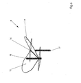
- the turntable 6 Like from the Fig. 4 . 5 and 6 can be seen, the turntable 6 according to the invention plate elements 14, 15.
- the plate elements 14, 15 form part of the intended for receiving piece goods surface of the turntable 6.
- the plate elements 14 and 15 are connected via a pivot axis 16 so that they can pivot relative to each other and, for example, in the Fig. 5 and 6 can take shown further operating positions.
- the turntable 6 has a rotary drive, with which the plate elements can be rotated about a vertical axis of rotation which passes through the surface center.
- the turntable 6 has two lifting elements 17, 18, with which the respective plate member 14, 15 can be raised.
- the conveyor trough 3, 4 according to the invention and the conveying device 5 according to the invention offer the advantage that the articles do not lie anywhere on a surface, but in the conveyor trough 3, 4 aligned in each case with an edge parallel to the groove throat or at least a pack with its edge in the throat of the conveyor trough 3, 4 lies.
- a pin 12 In the throat (in the bottom of the conveyor trough 3) moves a pin 12, which transports the pack along the conveyor trough 3.
- a sensor (not shown) monitors that the pin 12 pushes forward only until the package tilts out of the conveyor trough 3.
- the static friction on the channel wall 7, 8 can be selected with simple attempts that it is greater than the friction of article on article, but is so low that articles that fall into the conveyor trough 3, to the throat of the conveyor trough 3 slip ,
- a suitable friction and the pin 12 can drive a certain acceleration, whereby the pack, which is not in the frictional connection of the pin 12 is retained by the inertial forces.
- the separation is also improved if the conveyor trough 3 is provided with a second conveyor trough 4 extending through 90 ° thereto. If, in spite of everything, two packages lie on top of each other and are moved together by the pin 12, they would fall side by side into the next channel 4 and, because of the 90 ° orientation, will now lie one behind the other and can now be easily separated from this conveyor channel 4.
- the turntable 6 according to the invention consists of two semi-circular surfaces (plate elements 14, 15) which are hingedly connected to the circular center line and can be raised and lowered by adjusting cylinder on the outside of the circle.
- both a horizontal disc can be produced ( Fig. 4 ), as well as a V-shaped rotatable channel ( Fig. 6 ), as well as a sloping surface ( Fig. 5 ), which depending on how the disc was rotated, can slip off on any arbitrary side to be determined on an object thereon.
- the disc (plate elements 14, 15) is first in a channel shape ( Fig. 6 ) brought.
- the scattered article falls into the gutter and aligns with an edge along the gutter.
- a bar code on the bottom of the article can be read by a first (not shown) camera, in particular, if one of the plate elements is made of Plexiglas and the camera is directed diagonally from below onto the turntable.
- the oblique arrangement of the camera allows to arrange the camera outside the necessary for the rotational drive of the turntable mechanics.
- the plate is now placed horizontally, can be determined with simple distance sensors by turning the length and width of the article. Likewise, with these or another (also not shown) camera all four outer sides of the pack can be searched for a barcode. One (the) more camera above the article can also examine the top of the article on barcode and by the determine a height (not shown) distance sensors known lengths and heights in plan view.
- the package After determining the length, width, height, ID number and expiry date, the package can be rotated as it is to be picked up by the storage and retrieval unit. If it is transverse instead of long, then the plate is rotated by 90 °. If the pack is upright instead of flat, the gutter is once again made in a V-shape. The article falls on a surface; after lowering the surface of the article is then again transversely or longitudinally and can be brought into position as described above.
- the turntable may be skewed and the article slips into an error dispenser or lift, which transfers it to the bulk goods for one new attempt.
- Fig. 7 shows while maintaining the same reference numerals for the same components, that instead of in Fig. 1 and 2 shown conveyor belt 2, a further conveyor channel 20 according to the invention may be provided.
- this conveyor trough 20 the one surface of the trough boundary wall is formed by the surface of a conveyor belt 21 in one of the gutter boundary walls.
- the conveyor trough 21 trough plates 22, 23, 24, which simplify the pouring of cargo into the conveyor trough 21.
- Fig. 7 shows that the surfaces opposite the conveyor belt are formed by two stepped channel boundary walls 25 and 26. As a result, the conveyor chute 21 is subdivided in the core into two sub-conveyors.
- the conveyor 21 also has two independently of each other, in each case in the bottom of the respective sub-conveyor trough arranged bands (band 27 of the second sub-conveyor in the conveying direction is in Fig. 7 shown), to each of which a (not shown) thrust block is attached, which projects through a slot in the bottom of the respective sub-conveyor trough into the interior of the respective sub-trough to get there into engagement with cargo, located in the respective sub-trough is located.
- Fig. 7 shows Fig. 7 in that the plate elements 14, 15 of the turntable 6 can also be made rectangular.
- FIG. 7 a carriage 28 with which the plate elements 14, 15 can be moved.
- the plate elements 14, 15 can be moved after receiving a piece goods from the upstream conveyor trough 4 in order to create more space for pivoting one or the plate elements 14, 15.
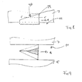
- Fig. 8 shows a side view of a usable in a conveyor chute 29.
- a slot 11 is provided, in which the thrust block 29 is arranged to be movable in the conveying direction A.
- Fig. 9 shows a sectional view of the thrust block 29 according to Fig. 8 along the line CC in Fig. 8 ,
- the thrust block 29 has an elongate shape and extends with its longitudinal extent in the conveying direction A and with its height in a direction perpendicular to the conveying direction A.
- the thrust block 29 has a triangular cross-sectional shape in a plane that is perpendicular to the height (see. Fig. 9 ).
- the cross-sectional shape (triangular) of the thrust block 29 is equal over a part of its height, while the size of the cross section changes while maintaining the cross-sectional shape, ie the thrust block is designed tapering toward its free end (see. Fig. 9 ).
- the one base of the triangle points forward, in the conveying direction.
- the tip points to the rear, against the direction of conveyance.
- the thrust block 29 also has a bevel 30, which descends from a higher, forward in the conveying direction level backwards, against the conveying direction in the direction of the bottom of the conveyor chute down.
Landscapes
- Engineering & Computer Science (AREA)
- Mechanical Engineering (AREA)
- Feeding Of Articles To Conveyors (AREA)
- Specific Conveyance Elements (AREA)
Applications Claiming Priority (1)
| Application Number | Priority Date | Filing Date | Title |
|---|---|---|---|
| DE102014013450 | 2014-09-17 |
Publications (2)
| Publication Number | Publication Date |
|---|---|
| EP3006379A2 true EP3006379A2 (fr) | 2016-04-13 |
| EP3006379A3 EP3006379A3 (fr) | 2016-07-27 |
Family
ID=54150212
Family Applications (1)
| Application Number | Title | Priority Date | Filing Date |
|---|---|---|---|
| EP15002697.9A Withdrawn EP3006379A3 (fr) | 2014-09-17 | 2015-09-17 | Goulotte de transport pour un automate de preparation de commande pour les pharmacies et dispositif de transport, plateau rotatif et automate de preparation de commande pour pharmacies et procede de fonctionnement d'une goulotte de transport |
Country Status (2)
| Country | Link |
|---|---|
| EP (1) | EP3006379A3 (fr) |
| DE (1) | DE202015009315U1 (fr) |
Cited By (20)
| Publication number | Priority date | Publication date | Assignee | Title |
|---|---|---|---|---|
| CN106617934A (zh) * | 2017-01-23 | 2017-05-10 | 上海擅韬信息技术有限公司 | 一种转盘式送药装置 |
| WO2018106800A1 (fr) * | 2016-12-06 | 2018-06-14 | Berkshire Grey, Inc. | Systèmes et procédés pour permettre le traitement d'objets dans des véhicules |
| CN108817903A (zh) * | 2018-08-08 | 2018-11-16 | 苏州上声电子股份有限公司 | 压条自动上料系统 |
| US10265872B2 (en) | 2015-09-09 | 2019-04-23 | Berkshire Grey, Inc. | Systems and methods for providing dynamic communicative lighting in a robotic environment |
| US10350755B2 (en) | 2016-02-08 | 2019-07-16 | Berkshire Grey, Inc. | Systems and methods for providing processing of a variety of objects employing motion planning |
| US10618745B2 (en) | 2016-12-09 | 2020-04-14 | Berkshire Grey, Inc. | Systems and methods for processing objects provided in vehicles |
| US10625305B2 (en) | 2015-12-04 | 2020-04-21 | Berkshire Grey, Inc. | Systems and methods for dynamic processing of objects |
| CN111392304A (zh) * | 2020-03-30 | 2020-07-10 | 新石器慧通(北京)科技有限公司 | 接货箱、物流车及系统 |
| US10730078B2 (en) | 2015-12-04 | 2020-08-04 | Berkshire Grey, Inc. | Systems and methods for dynamic sortation of objects |
| US10792706B2 (en) | 2017-04-24 | 2020-10-06 | Berkshire Grey, Inc. | Systems and methods for providing singulation of objects for processing using object movement redistribution |
| US10793375B2 (en) | 2016-11-08 | 2020-10-06 | Berkshire Grey, Inc. | Systems and methods for processing objects |
| CN111891709A (zh) * | 2020-07-21 | 2020-11-06 | 湖州隆升机械有限公司 | 基于轮胎整理的自动化机械手结构 |
| US10913615B2 (en) | 2016-11-28 | 2021-02-09 | Berkshire Grey, Inc. | Systems and methods for providing singulation of objects for processing |
| CN112591363A (zh) * | 2020-12-23 | 2021-04-02 | 苏州英特吉医疗设备有限公司 | 一种发药机 |
| EP3854730A1 (fr) * | 2020-01-24 | 2021-07-28 | Becton Dickinson Rowa Germany GmbH | Dispositif et procédé d'identification, de mesure et de positionnement de marchandises de détail |
| US11267662B2 (en) | 2019-02-27 | 2022-03-08 | Berkshire Grey, Inc. | Systems and methods for controlling the disgorging of objects in containers by vibratory motion |
| US11427407B2 (en) | 2020-01-24 | 2022-08-30 | Becton Dickinson Rowa Germany Gmbh | Apparatus and method for identifying, measuring and positioning piece goods |
| CN115321073A (zh) * | 2022-09-01 | 2022-11-11 | 苏州英特吉医疗设备有限公司 | 发药机加药装置及发药机的加药方法 |
| CN116424736A (zh) * | 2023-04-17 | 2023-07-14 | 中国建筑一局(集团)有限公司 | 一种模块化负压隔离病房及负压隔离区 |
| US11866269B2 (en) | 2021-10-06 | 2024-01-09 | Berkshire Grey Operating Company, Inc. | Dynamic processing of objects provided in elevated vehicles with evacuation systems and methods for receiving objects |
Citations (1)
| Publication number | Priority date | Publication date | Assignee | Title |
|---|---|---|---|---|
| DE102004012133A1 (de) | 2003-09-10 | 2005-05-04 | Indunorm Bewegungstechnik Gmbh | Vorrichtung zum Vereinzeln im wesentlichen quaderförmiger Stückgüter verschiedenster Abmessungen, insbesondere von Arzneimittelpackungen |
Family Cites Families (4)
| Publication number | Priority date | Publication date | Assignee | Title |
|---|---|---|---|---|
| US3502199A (en) * | 1968-03-11 | 1970-03-24 | May Fran Mfg Corp | Conveyor assembly |
| US6662929B1 (en) * | 2000-11-17 | 2003-12-16 | Lockhead Martin Corporation | Parcel singulation software control logic |
| DE202008001683U1 (de) * | 2008-02-06 | 2008-07-03 | Beils, Dirk Rolf | Automatisierte Einlagerungsvorrichtung für ein Apothekerlager |
| DE102009013245A1 (de) * | 2009-03-14 | 2010-09-16 | Wincor Nixdorf International Gmbh | Vorrichtung zum Transportieren von Leergut |
-
2015
- 2015-09-17 EP EP15002697.9A patent/EP3006379A3/fr not_active Withdrawn
- 2015-09-17 DE DE202015009315.9U patent/DE202015009315U1/de not_active Expired - Lifetime
Patent Citations (1)
| Publication number | Priority date | Publication date | Assignee | Title |
|---|---|---|---|---|
| DE102004012133A1 (de) | 2003-09-10 | 2005-05-04 | Indunorm Bewegungstechnik Gmbh | Vorrichtung zum Vereinzeln im wesentlichen quaderförmiger Stückgüter verschiedenster Abmessungen, insbesondere von Arzneimittelpackungen |
Cited By (56)
| Publication number | Priority date | Publication date | Assignee | Title |
|---|---|---|---|---|
| US12491646B2 (en) | 2015-09-09 | 2025-12-09 | Berkshire Grey Operating Company, Inc. | Systems and methods for providing dynamic communicative lighting in a robotic environment |
| US10265872B2 (en) | 2015-09-09 | 2019-04-23 | Berkshire Grey, Inc. | Systems and methods for providing dynamic communicative lighting in a robotic environment |
| US11813741B2 (en) | 2015-09-09 | 2023-11-14 | Berkshire Grey Operating Company, Inc. | Systems and methods for providing dynamic communicative lighting in a robotic environment |
| US10632631B2 (en) | 2015-09-09 | 2020-04-28 | Berkshire Grey, Inc. | Systems and methods for providing dynamic communicative lighting in a robotic environment |
| US11117271B2 (en) | 2015-09-09 | 2021-09-14 | Berkshire Grey, Inc. | Systems and methods for providing dynamic communicative lighting in a robotic environment |
| US12076752B2 (en) | 2015-12-04 | 2024-09-03 | Berkshire Grey Operating Company, Inc. | Systems and methods for dynamic processing of objects |
| US11458507B2 (en) | 2015-12-04 | 2022-10-04 | Berkshire Grey Operating Company, Inc. | Systems and methods for dynamic processing of objects |
| US11400491B2 (en) | 2015-12-04 | 2022-08-02 | Berkshire Grey Operating Company, Inc. | Systems and methods for dynamic sortation of objects |
| US10625305B2 (en) | 2015-12-04 | 2020-04-21 | Berkshire Grey, Inc. | Systems and methods for dynamic processing of objects |
| US12337353B2 (en) | 2015-12-04 | 2025-06-24 | Berkshire Grey Operating Company, Inc. | Systems and methods for dynamic sortation of objects |
| US10730078B2 (en) | 2015-12-04 | 2020-08-04 | Berkshire Grey, Inc. | Systems and methods for dynamic sortation of objects |
| US11839902B2 (en) | 2015-12-04 | 2023-12-12 | Berkshire Grey Operating Company, Inc. | Systems and methods for dynamic sortation of objects |
| US11123866B2 (en) | 2016-02-08 | 2021-09-21 | Berkshire Grey, Inc. | Systems and methods for providing processing of a variety of objects employing motion planning |
| US11724394B2 (en) | 2016-02-08 | 2023-08-15 | Berkshire Grey Operating Company, Inc. | Systems and methods for providing processing of a variety of objects employing motion planning |
| US12109708B2 (en) | 2016-02-08 | 2024-10-08 | Berkshire Grey Operating Company, Inc. | Systems and methods for providing processing of a variety of objects employing motion planning |
| US10350755B2 (en) | 2016-02-08 | 2019-07-16 | Berkshire Grey, Inc. | Systems and methods for providing processing of a variety of objects employing motion planning |
| US11213949B2 (en) | 2016-02-08 | 2022-01-04 | Berkshire Grey, Inc. | Systems and methods for providing processing of a variety of objects employing motion planning |
| US12286310B2 (en) | 2016-11-08 | 2025-04-29 | Berkshire Grey Operating Company, Inc. | Systems and methods for processing objects |
| US11780684B2 (en) | 2016-11-08 | 2023-10-10 | Berkshire Grey Operating Company, Inc. | Systems and methods for processing objects |
| US10793375B2 (en) | 2016-11-08 | 2020-10-06 | Berkshire Grey, Inc. | Systems and methods for processing objects |
| US11492210B2 (en) | 2016-11-28 | 2022-11-08 | Berkshire Grey Operating Company, Inc. | Systems and methods for providing singulation of objects for processing |
| US11820605B2 (en) | 2016-11-28 | 2023-11-21 | Berkshire Grey Operating Company, Inc. | Systems and methods for providing singulation of objects for processing |
| US12168577B2 (en) | 2016-11-28 | 2024-12-17 | Berkshire Grey Operating Company, Inc. | Systems and methods for providing singulation of objects for processing |
| US10913614B2 (en) | 2016-11-28 | 2021-02-09 | Berkshire Grey, Inc. | Systems and methods for providing singulation of objects for processing |
| US10913615B2 (en) | 2016-11-28 | 2021-02-09 | Berkshire Grey, Inc. | Systems and methods for providing singulation of objects for processing |
| US10875057B2 (en) | 2016-12-06 | 2020-12-29 | Berkshire Grey, Inc. | Systems and methods for providing for the processing of objects in vehicles |
| US11945003B2 (en) | 2016-12-06 | 2024-04-02 | Berkshire Grey Operating Company, Inc. | Systems and methods for providing for the processing of objects in vehicles |
| US12434270B2 (en) | 2016-12-06 | 2025-10-07 | Berkshire Grey Operating Company, Inc. | Systems and methods for providing for the processing of objects in vehicles |
| US11400493B2 (en) | 2016-12-06 | 2022-08-02 | Berkshire Grey Operating Company, Inc. | Systems and methods for providing for the processing of objects in vehicles |
| WO2018106800A1 (fr) * | 2016-12-06 | 2018-06-14 | Berkshire Grey, Inc. | Systèmes et procédés pour permettre le traitement d'objets dans des véhicules |
| US11471917B2 (en) | 2016-12-06 | 2022-10-18 | Berkshire Grey Operating Company, Inc. | Systems and methods for providing for the processing of objects in vehicles |
| US11884495B2 (en) | 2016-12-09 | 2024-01-30 | Berkshire Grey Operating Company, Inc. | Systems and methods for processing objects provided in vehicles |
| US10618745B2 (en) | 2016-12-09 | 2020-04-14 | Berkshire Grey, Inc. | Systems and methods for processing objects provided in vehicles |
| US12180014B2 (en) | 2016-12-09 | 2024-12-31 | Berkshire Grey Operating Company, Inc. | Systems and methods for processing objects provided in vehicles |
| US11034529B2 (en) | 2016-12-09 | 2021-06-15 | Berkshire Grey, Inc. | Systems and methods for processing objects provided in vehicles |
| CN106617934A (zh) * | 2017-01-23 | 2017-05-10 | 上海擅韬信息技术有限公司 | 一种转盘式送药装置 |
| CN106617934B (zh) * | 2017-01-23 | 2023-06-23 | 上海擅韬信息技术有限公司 | 一种转盘式送药装置 |
| US10792706B2 (en) | 2017-04-24 | 2020-10-06 | Berkshire Grey, Inc. | Systems and methods for providing singulation of objects for processing using object movement redistribution |
| US11826787B2 (en) | 2017-04-24 | 2023-11-28 | Berkshire Grey Operating Company, Inc. | Systems and methods for providing singulation of objects for processing using object movement redistribution |
| US12404117B2 (en) | 2017-04-24 | 2025-09-02 | Berkshire Grey Operating Company, Inc. | Systems and methods for providing singulation of objects for processing using object movement redistribution |
| CN108817903A (zh) * | 2018-08-08 | 2018-11-16 | 苏州上声电子股份有限公司 | 压条自动上料系统 |
| US12145811B2 (en) | 2019-02-27 | 2024-11-19 | Berkshire Grey Operating Company, Inc. | Systems and methods for controlling the disgorging of objects in containers by vibratory motion |
| US11267662B2 (en) | 2019-02-27 | 2022-03-08 | Berkshire Grey, Inc. | Systems and methods for controlling the disgorging of objects in containers by vibratory motion |
| AU2021210126B2 (en) * | 2020-01-24 | 2026-04-02 | Becton Dickinson Rowa Germany Gmbh | Apparatus and method for identifying, measuring and positioning piece goods |
| US11427407B2 (en) | 2020-01-24 | 2022-08-30 | Becton Dickinson Rowa Germany Gmbh | Apparatus and method for identifying, measuring and positioning piece goods |
| EP3854730A1 (fr) * | 2020-01-24 | 2021-07-28 | Becton Dickinson Rowa Germany GmbH | Dispositif et procédé d'identification, de mesure et de positionnement de marchandises de détail |
| CN115023404A (zh) * | 2020-01-24 | 2022-09-06 | 贝克顿迪金森罗瓦德国有限公司 | 用于识别、测量和定位计件货物的设备和方法 |
| WO2021148384A1 (fr) * | 2020-01-24 | 2021-07-29 | Becton Dickinson Rowa Germany Gmbh | Appareil et procédé d'identification, de mesure et de positionnement de marchandises de détail |
| CN111392304A (zh) * | 2020-03-30 | 2020-07-10 | 新石器慧通(北京)科技有限公司 | 接货箱、物流车及系统 |
| CN111891709B (zh) * | 2020-07-21 | 2021-12-07 | 台州市新峰轴承有限公司 | 基于轮胎整理的自动化机械手结构 |
| CN111891709A (zh) * | 2020-07-21 | 2020-11-06 | 湖州隆升机械有限公司 | 基于轮胎整理的自动化机械手结构 |
| CN112591363A (zh) * | 2020-12-23 | 2021-04-02 | 苏州英特吉医疗设备有限公司 | 一种发药机 |
| US12129127B2 (en) | 2021-10-06 | 2024-10-29 | Berkshire Grey Operating Company, Inc. | Dynamic processing of objects provided in elevated vehicles with evacuation systems and methods for receiving objects |
| US11866269B2 (en) | 2021-10-06 | 2024-01-09 | Berkshire Grey Operating Company, Inc. | Dynamic processing of objects provided in elevated vehicles with evacuation systems and methods for receiving objects |
| CN115321073A (zh) * | 2022-09-01 | 2022-11-11 | 苏州英特吉医疗设备有限公司 | 发药机加药装置及发药机的加药方法 |
| CN116424736A (zh) * | 2023-04-17 | 2023-07-14 | 中国建筑一局(集团)有限公司 | 一种模块化负压隔离病房及负压隔离区 |
Also Published As
| Publication number | Publication date |
|---|---|
| EP3006379A3 (fr) | 2016-07-27 |
| DE202015009315U1 (de) | 2017-03-21 |
Similar Documents
| Publication | Publication Date | Title |
|---|---|---|
| EP3006379A2 (fr) | Goulotte de transport pour un automate de preparation de commande pour les pharmacies et dispositif de transport, plateau rotatif et automate de preparation de commande pour pharmacies et procede de fonctionnement d'une goulotte de transport | |
| EP3889076B1 (fr) | Système de préparation de commandes et procédé de préparation de commandes | |
| DE69838884T2 (de) | Maschine zum Verpacken von Tabletten | |
| EP2155587B1 (fr) | Poste de basculement et poste de rotation pour installations de préparation de commandes | |
| EP2315714B1 (fr) | Dispositif entièrement automatique de préparation d'articles dans des contenants de commandes | |
| EP1598291B1 (fr) | Dispositif et procédé automatique de stockage d'objets | |
| EP3330200A1 (fr) | Procédé de stockage et de distribution d'objets ainsi que système de stockage permettant la mise en uvre dudit procédé | |
| EP1900654B1 (fr) | Automate de réception des marchandises | |
| EP3889077B1 (fr) | Système de préparation des commandes | |
| DE102009038124A1 (de) | Lager- und Kommissioniersystem mit einem universell einsetzbaren Winkelladungsträger | |
| EP2194008A2 (fr) | Procédé et dispositif de stockage de boîtes de médicaments | |
| WO2017207231A1 (fr) | Automate de préparation de commande comprenant un dispositif de remplissage d'une rangée de récipients de transport en respectivement un groupe d'emballages de médicaments correspondant à une commande | |
| DE102006039697A1 (de) | Vorrichtung und Verfahren zum Entladen von mit Palettenlagen beladenen Tablaren | |
| DE202006014375U1 (de) | Warenlager | |
| WO2016110528A1 (fr) | Dispositif de préparation de commandes et procédé de stockage de marchandises avec le dispositif de préparation de commandes | |
| DE20214241U1 (de) | Lagervorrichtung | |
| EP1818283B1 (fr) | Procédé de stockage de marchandises au détail dans un entrepôt de marchandises au détail automatisé | |
| DE102004012133B4 (de) | Vorrichtung zum Vereinzeln quaderförmiger Stückgüter verschiedenster Abmessungen, insbesondere von Arzneimittelpackungen | |
| EP2163491B1 (fr) | Automate de stockage | |
| EP2769935A1 (fr) | Dispositif de préparation des commandes et procédé de préparation des commandes | |
| EP1524209B1 (fr) | Méthode et dispositif pour prélever simultanément plusieurs articles d'un magasin à rayonnage | |
| EP0416627B1 (fr) | Procédé et dispositif pour stocker et reprendre automatiquement des sortes de marchandises de détail de rayonnages dans de grands entrepôts | |
| EP2015265B1 (fr) | Système d'étagères obliques | |
| AT511598B1 (de) | Automatisiertes warenumschlaglager | |
| DE102023111671B4 (de) | Lager- und Ausgabesystem sowie Lager- und Ausgabeverfahren |
Legal Events
| Date | Code | Title | Description |
|---|---|---|---|
| PUAI | Public reference made under article 153(3) epc to a published international application that has entered the european phase |
Free format text: ORIGINAL CODE: 0009012 |
|
| AK | Designated contracting states |
Kind code of ref document: A2 Designated state(s): AL AT BE BG CH CY CZ DE DK EE ES FI FR GB GR HR HU IE IS IT LI LT LU LV MC MK MT NL NO PL PT RO RS SE SI SK SM TR |
|
| AX | Request for extension of the european patent |
Extension state: BA ME |
|
| PUAL | Search report despatched |
Free format text: ORIGINAL CODE: 0009013 |
|
| RIC1 | Information provided on ipc code assigned before grant |
Ipc: B65G 1/137 20060101ALI20160616BHEP Ipc: B65G 19/02 20060101AFI20160616BHEP Ipc: B65G 47/14 20060101ALI20160616BHEP Ipc: B65G 47/08 20060101ALI20160616BHEP |
|
| AK | Designated contracting states |
Kind code of ref document: A3 Designated state(s): AL AT BE BG CH CY CZ DE DK EE ES FI FR GB GR HR HU IE IS IT LI LT LU LV MC MK MT NL NO PL PT RO RS SE SI SK SM TR |
|
| AX | Request for extension of the european patent |
Extension state: BA ME |
|
| STAA | Information on the status of an ep patent application or granted ep patent |
Free format text: STATUS: THE APPLICATION IS DEEMED TO BE WITHDRAWN |
|
| 18D | Application deemed to be withdrawn |
Effective date: 20170128 |