EP3013443B1 - Appareil de sport, notamment aide motorisée à la montée pour ski de randonnée - Google Patents
Appareil de sport, notamment aide motorisée à la montée pour ski de randonnée Download PDFInfo
- Publication number
- EP3013443B1 EP3013443B1 EP14750425.2A EP14750425A EP3013443B1 EP 3013443 B1 EP3013443 B1 EP 3013443B1 EP 14750425 A EP14750425 A EP 14750425A EP 3013443 B1 EP3013443 B1 EP 3013443B1
- Authority
- EP
- European Patent Office
- Prior art keywords
- sports equipment
- slider
- binding
- equipment according
- binding device
- Prior art date
- Legal status (The legal status is an assumption and is not a legal conclusion. Google has not performed a legal analysis and makes no representation as to the accuracy of the status listed.)
- Active
Links
Images






Classifications
-
- A—HUMAN NECESSITIES
- A63—SPORTS; GAMES; AMUSEMENTS
- A63C—SKATES; SKIS; ROLLER SKATES; DESIGN OR LAYOUT OF COURTS, RINKS OR THE LIKE
- A63C5/00—Skis or snowboards
- A63C5/08—Skis or snowboards motor-driven
-
- A—HUMAN NECESSITIES
- A63—SPORTS; GAMES; AMUSEMENTS
- A63C—SKATES; SKIS; ROLLER SKATES; DESIGN OR LAYOUT OF COURTS, RINKS OR THE LIKE
- A63C9/00—Ski bindings
- A63C9/003—Non-swivel sole plate fixed on the ski
-
- A—HUMAN NECESSITIES
- A63—SPORTS; GAMES; AMUSEMENTS
- A63C—SKATES; SKIS; ROLLER SKATES; DESIGN OR LAYOUT OF COURTS, RINKS OR THE LIKE
- A63C9/00—Ski bindings
- A63C9/08—Ski bindings yieldable or self-releasing in the event of an accident, i.e. safety bindings
- A63C9/0807—Ski bindings yieldable or self-releasing in the event of an accident, i.e. safety bindings for both towing and downhill skiing
-
- A—HUMAN NECESSITIES
- A63—SPORTS; GAMES; AMUSEMENTS
- A63C—SKATES; SKIS; ROLLER SKATES; DESIGN OR LAYOUT OF COURTS, RINKS OR THE LIKE
- A63C9/00—Ski bindings
- A63C2009/008—Ski bindings with a binding element sliding along a rail during use or setting
Definitions
- the invention relates to a motorized device for skis, in particular for touring skis, which supports the ascent movement and thus with less physical performance that needed to go uphill, alternating ski after pushing, can be performed.
- the invention relates to a sports equipment, as indicated in claims 1 and 5.
- a sports equipment in particular a climbing ski or touring ski is known, which has a fold-out Abcetschaufel on the seen in the direction of movement front end portion.
- This shovel is arranged on the ski so that it can be folded out in the direction of the ground and thus can intervene in the snow.
- the downwardly foldable Abcetschaufel is connected to a linkage, which is guided for binding. If the user lowers his foot while walking and thus loads the binding with his body weight, the linkage is activated by the body weight. As a result, the Ab complicatschaufel is unfolded and also pulled backwards, so that the ski slides forward.
- the in the DE 649 153 described embodiment has the disadvantage that the Abagneschaufel must engage in the snow to be able to achieve that the ski is moved by the Abagneschaufel forward.
- the impeller In hard snow, especially in ice or compact snow, the impeller can not be sufficiently pressed into the snow to ensure a good grip.
- the snow ground of the repeller blade can not resist enough to absorb the force transmitted by the repeller blade.
- the Absteschaufel can not achieve the desired effect in the prevailing snow conditions.
- a sports device with the features of the preamble of claim 1 is made DE 10 2005 043 810 A1 known.
- the present invention has for its object to provide an improved sports equipment, which provides a good ascent assistance in a variety of different snow conditions and allows a workable support in locomotion in the field or in the plane.
- the invention has the object to design a touring ski so that the movement and the posture of Tourenskigehers is not changed, only the energy consumption can be reduced by motor support.
- This object of the invention is achieved by a motor climbing aid for touring skiers or by a sports equipment, in particular by a Tourenskianssen, with the features of claim 1.
- the invention solves the problem in that between Tourenskioberseite and touring ski binding a sliding device is mounted, which is mounted on the top of the ski, or integrated in the ski and the touring ski binding is mounted on the slider.
- the sliding device serves to allow the binding to be moved in the longitudinal direction from the ski center in the direction of the ski tip and in the direction of the ski end.
- the touring ski binding on the sliding device is pulled by a motor, preferably an electric motor, alternately controlled by the rotational movement of the touring ski binding and / or the load switch, which is actuated by loading and unloading of the touring skier in the direction of the ski tip or back to the ski end.
- the movement of the touring ski binding can be made with known technology such as rack, threaded rod, pneumatic or hydraulic cylinder or with cable.
- a first possible embodiment is a ski touring, consisting of a sliding surface, to which a fur or fur-like plastic is attached to prevent slipping back when walking uphill. Furthermore, there is a touring ski binding on the ski touring. The ski boot snaps into this binding, creating the connection between touring skis and touring skis.
- a touring ski binding is designed so that the fixation can be solved at the heel to go and the shoe with the binding, in the toe area, is rotatably connected to the ski. For downhill skiing, the shoe is fixed in the heel area.
- a possible advantageous embodiment of the sports device according to the invention is a Tourenskian Aunt.
- the sports equipment comprises a sliding body on which an underside is designed as a sliding surface, which sliding surface essentially corresponds to the surface projected in the direction of an upper side of the sliding body.
- the sports device comprises a arranged on the upper side of the slider binding device, especially touring ski binding for releasably attaching a sports shoe of a user, as required, and a storage device through which the binding device, in particular a shoe holder part of the binding device, supported by the bearing device relative to the slider along the longitudinal direction adjustable is.
- a connectable to a power supply device drive device is formed, through which the binding device is actively and oscillating coupled to the walking path of the user in the longitudinal direction of the slider slidably.
- An oscillating displacement of the binding device For the purposes of this document means that during the walking movement of the user who has two sports equipment according to the invention strapped to his feet, the binding device is moved relative to the slider in the longitudinal direction before and back again. The time of the shift, or the direction of displacement depends on the movement or the speed of movement of the user. Thus, the oscillating motion does not have to be periodic, but oscillating rather means that the movement is repetitively executed while using the sports equipment in the ascent.
- An advantage of the solution according to the invention is that the binding device can be moved actively and oscillating in the longitudinal direction of the sports device by the bearing device and the associated drive device. As a result, a step length of the user can be extended or a distance covered per step of the user by the sports equipment can be increased, whereby the user only has to muster a reduced work capacity for climbing a mountain or for locomotion in the plane and thus can save power or body energy .
- the embodiment of the invention further has the advantage that the specified construction to support the user can be relatively easily constructed. On the one hand this weight can be saved and on the other hand, only a few moving parts on the sports equipment available, whereby the robustness or functional reliability of the sports equipment is increased.
- the bearing device with the drive unit can also be easily attached to any standard sliding body, such as a classic touring ski.
- a conventional climbing skin may be used.
- the sports equipment can be quickly and easily converted from an ascent to a downhill state - and vice versa -. Due to the advantageous construction, the handling characteristics are not or hardly worsened compared to a conventional touring ski both in the ascent state and in the downhill state of the sports equipment. Another advantage is that almost conventional gliding equipment or skis can be used, which have already proven themselves many times in practice.
- the gliding device no structurally complex special constructions for the gliding device are required, whereby the cost of creating the sports equipment can be kept as low as possible.
- the insurrection height of the user relative to the ground is kept relatively low by the specified measures.
- the inventive Sports equipment a relatively small number of mechanical components or moving parts, such as joints or management organs, so that even under adverse conditions, especially in the environment of snow, a high functional reliability and functional stability can be achieved.
- the bearing device comprises a linear guide, in particular a profiled rail guide such as a linear sliding guide or a linear ball guide.
- a linear guide in particular a profiled rail guide such as a linear sliding guide or a linear ball guide.
- the advantage here is that can be moved actively and precisely against the slider in the longitudinal direction by such a linear guide the shoe holder part of the binding device in which a sports shoe is added.
- a guide rail of the linear guide is attached to the sliding body or integrated in the latter, and at least one guide slide corresponding to the linear guide is fastened to the binding device or integrated into it.
- the drive device comprises an electric motor, by means of which the binding is displaceable relative to the sliding body.
- an electric motor with respect to an internal combustion engine is very quiet.
- an electric motor can be built as small as possible and weight saving.
- an electric motor is particularly low maintenance and maintenance-free and well controlled or regulated in terms of its drive behavior and its drive power.
- Another great advantage of an electric motor is that it can be operated in an environmentally friendly manner and that no flammable liquids or other dangerous fuels have to be carried along.
- the electric motor is designed as a spindle motor or, optionally via a transmission, is coupled to an adjusting spindle.
- the advantage here is that an electric motor with an adjusting spindle allows rapid adjustment or a practicable positioning of the bearing device or the binding device.
- the electric motor optionally via a transmission, is coupled to a gear which engages in a corresponding toothed rack.
- a gear which engages in a rack has only a small inertia, whereby a dynamic positioning of the bearing device can take place and an optimized operation of the sports equipment can be achieved.
- the gear together with the drive unit can be easily removed from the slider, whereby the handling properties in the downhill state of the sports device or the slider can be improved especially.
- the electric motor optionally via a transmission, is coupled to a cable drive drum.
- a structure with a cable drive drum can be performed easily and inexpensively.
- Such a structure is also very robust and resistant or insensitive to environmental influences.
- the drive device comprises an actuating cylinder, such as a pneumatic cylinder or a hydraulic cylinder, through which the binding device is displaceable relative to the sliding body.
- an actuating cylinder such as a pneumatic cylinder or a hydraulic cylinder
- the binding device is displaceable relative to the sliding body.
- the drive device comprises a crank mechanism, in particular a crankshaft together with a connecting rod, through which the binding device is displaceable relative to the sliding body. It is advantageous that such a crank mechanism is very simple. An electric motor for driving the crank mechanism also only needs to rotate in one direction of rotation in order to be able to accomplish the oscillating displacement of the binding device.
- an electrotechnical control unit is connected to the drive device and designed to control the drive device, which control unit comprises a digital input device or a potentiometer, by which a movement speed, a duty cycle, switching times and / or a travel of the drive device can be predetermined or is variably adjustable.
- control unit comprises a digital input device or a potentiometer, by which a movement speed, a duty cycle, switching times and / or a travel of the drive device can be predetermined or is variably adjustable.
- control unit is connected to at least one detection means, for example a switching contact or an electrotechnical sensor, for detecting an activation command for the drive device.
- detection means for example a switching contact or an electrotechnical sensor
- the activation command for the drive device can be specified by the user or at least influenced or co-determined. In particular, this ensures a user-aware activation or deactivation and / or influencing of the support performance of the drive device. The behavior of the sports equipment can thus be adjusted spontaneously or well and to the individual needs of the user or to the changing circumstances and environmental conditions.
- the at least one detection means for detecting a control command actively or deliberately initiated by a user and / or for detecting a movement state caused by the physiological movement for example a predetermined rotational angle position of the binding device relative to the sliding body or a pressure load against the sliding body, is formed, and that the drive device is driven in response to the detection states of the at least one detection means.
- the controller responds to deliberately or manually set commands and / or responded to unconsciously or automatically set, in particular to the physiological walking or moving sequence coupled commands of the user, and thus optimally operated the sports equipment or can be used optimally.
- the travel path of the binding relative to the sliding body is between 40 mm and 600 mm, in particular between 200 mm and 500 mm, preferably between 250 mm and 350 mm.
- this range of travel or active travel has been found to be advantageous, since in this area the structural complexity can be kept low for the sports equipment and still sufficient stride lengthening or Fortschulsunterstützung can be achieved in order to achieve an advantageous operation of the sports equipment can.
- the electric motor and the transmission are accommodated in a ring gear, wherein an outer casing of the ring gear has a circumferential toothing.
- the linear guide has a toothing, in which engages the gear, or the circumferential toothing of the ring gear meshing.
- the drive device is coupled in movement with the binding device and is displaceable simultaneously with the binding device relative to the sliding body.
- the advantage here is that the drive device can be easily attached to the binding device or can form a compact structural unit with this.
- the drive device can be mounted and dismounted as required by means of at least one coupling device on the slider or on the binding device.
- the advantage here is that in particular the handling properties of the slider can be improved in the downhill state, since the additional mass of the drive device does not act on the slider or is not coupled to the slider.
- the bearing device comprises a locking device, by means of which the guide carriage, and thus the binding device, in its position with respect to the longitudinal direction relative to the guide rail, and thus against the sliding body, can be locked.
- the motorized Tourenskiaufieris Vietnamese invention consists of the touring ski 103 with mounted on the tread tour skis 104.
- the slider 105 On the top of the touring ski is the slider 105, on the slider 105, the touring ski binding 102 is attached, which serves for fixing the ski boot 101.
- a motor 106 is mounted on the ski touring 103, which is provided in this embodiment with a threaded spindle 107.
- the touring ski binding 102 is mounted and a threaded nut 108 mounted so that depending on the direction of rotation of the motor 106 driven threaded spindle 107, the touring ski binding 102 is pushed on the slider 105 in the direction of ski tip or end of the ski.
- the thrust direction of touring ski binding 102 is as after Fig. 1 and Fig. 2 controlled by rotational movement of the touring ski binding 102, represented by arrows. Furthermore, the control of the reciprocating movement of touring ski binding 102 with the load switch 109, also shown with arrows done.
- the invention thus relates to a motor-operated device for skis, especially for touring skis, whereby the physical effort of Tourenskigehers is reduced by means of electric motor.
- the invention solves the problem in that there is a sliding device 105 between touring ski 103 and touring ski binding 102 on which the touring ski binding 102 by means of motor 106, between the ski and ski tip, is moved back and forth, causing the feet of the Tourenskigehers alternately on the ski before be pushed.
- Fig. 3 shows a perspective view of a sports equipment 1, in particular a Tourenskian Aunt.
- the sports equipment 1 comprises a sliding body 2 on which an underside 3 is designed as a sliding surface 4.
- the underside 3 of the slider 2 may include a low-friction and at the same time wear-resistant tread covering, for example made of polyethylene, in relation to snow or ice, or be formed by it.
- a binding device 6 is arranged, which serves to receive a sports shoe 7 of a user 8.
- the binding device 6 is to be understood as a coupling device which allows at least one as needed activatable and deactivatable connection between a sports shoe and the sports equipment 1.
- the sliding surface 4 preferably extends over the entire length 9 of the slider 2 and over the entire width 10 of the slider 2 and thus corresponds in their dimensions In particular, the largest part or the predominant area proportion of the underside 3 of the sliding body 2 is thereby covered or formed by the sliding surface 4.
- One exception here may be so-called steel or control edges, which may be attached to the underside 3 of the slider 2 at the two longitudinal side edges.
- the sliding surface 4 substantially corresponds to the surface 11 projected in the direction of an upper side 5 of the sliding body 2.
- the sliding surface 4 is that surface which rests on the ground 12, such as snow or ice, in the downhill state of the slider 2.
- a front blade section and a possibly formed rear blade section of the sliding body 2 preferably also form the sliding friction reducing sliding surface 4 on the underside facing the ground.
- Sporting device 1 shown a bearing device 13, by which the binding device 6, in particular at least one shoe holder part 14 of the binding device 6 relative to the slider 2 along the longitudinal direction 15 is adjustably supported.
- the adjustable relative to the slider 2 Schuhalterungsteil 14 is expediently defined at least by the front shoe support assembly, in particular formed by the so-called toe of the binding device 6.
- the sports device 1 comprises a drive device 16 through which the binding device 6, in particular at least its front shoe holder part 14 during the walking movement of the user 8, if necessary, in the longitudinal direction 15 of the slider 2 is displaceable.
- the drive device 16 can be connected to a power supply device 17.
- the drive device 16 is preferably designed such that at least the active adjustment movement or relative movement of the binding device 6 or the shoe support part 14 in the forward direction, ie in the direction of the so-called blade or ski tip of the slider 2 is accomplished. It may be expedient if by the drive device 16 also a return movement of the binding device 6 and the shoe mounting part 14, starting from an advanced position - Fig. 4 - in the initial or basic position - Fig. 3 - implemented or accomplished. Alternatively or in combination, it is also possible to execute at least one adjusting movement, in particular the return movement, by utilizing the gravitational effect or at least to support an actuating movement by gravity. According to an advantageous embodiment, the drive device 16 causes a periodically or acyclically recurring, active adjustment or an electromotive relative positioning of the binding device 6 relative to the slider 2 in the direction forward and back again.
- the bearing device 13 comprises a linear guide, in particular a profiled rail guide 18 such as a linear sliding guide or a linear ball guide.
- a linear sliding guide has the advantage that it is very robust and inexpensive to purchase.
- a linear ball guide has the advantage that it is very smooth in its movement and only a small clearance is available.
- Such a profile rail guide 18 usually comprises a guide rail 19 and a guide carriage 20, which is accommodated on the guide rail 19 and can be displaced or positioned by means of the drive device 16 along the guide rail 19.
- the guide rail 19 of the linear guide is attached to the slider 2 and connected at least one of the guide rail 19 corresponding guide carriage 20 with the binding device 6.
- the guide rail 19 is integrated in the slider 2 and / or that the guide carriage 20 is integrated into the binding device 6.
- guide rail 19 and guide carriage 20 it can be provided that the guide rail 19 is attached to the binding device 6 and that the guide carriage 20 is fastened to the sliding body 2.
- two or more guide carriages 20 are used instead of only one guide carriage 20, two or more guide carriages 20 are used.
- the use of a plurality of guide carriages 20 has the advantage that the load of the user 8 is better distributed, or that the load applied by the user 8 is picked up locally.
- the drive device 16 comprises an electric motor 21, by means of which the binding device 6 can be positioned relative to the sliding body 2 in an actively displaceable manner or by using stored electrical energy in the longitudinal direction 15 of the sliding body 2.
- the drive device 16 there are various technical design options for the drive device 16, which will be described in more detail below.
- the electric motor 21 is coupled to an adjusting spindle 22 which cooperates with a spindle nut 23 and thus converts a rotational movement of the electric motor 21 into a translational movement, in particular into a displacement of the binding device 6 along the longitudinal direction 15.
- the drive device 16 comprises a gear 24, which is connected between the electric motor 21 and the adjusting spindle 22 and thus provides for the translation into a suitable drive speed or driving force.
- the gear 24 can provide a reduction or for a translation in the sense of increasing the rotational speed of the adjusting spindle 22 in comparison to the electric motor 21.
- the adjusting spindle 22 is rotatable, but mounted in the longitudinal direction 15 immovably on the sliding body 2.
- This axial fixing of the adjusting spindle 22 can be done by any known from the prior art spindle bearings.
- the spindle nut 23 is coupled for movement with the guide carriage 20 so that the rotational movement of the adjusting spindle 22 can be converted into a translatory movement of the spindle nut 23 or of the at least one guide carriage 20.
- a spindle motor is formed, in which the spindle nut 23 is integrated and in which the adjusting spindle 22 is coupled for movement with the guide carriage 20 and thus in the longitudinal direction 15 is displaceable.
- the spindle nut is held fixed in position relative to the longitudinal direction 15 of the sports device 1.
- the binding device 6 is in its initial or home position 25. If the binding device 6 is actively moved forward by the drive device 16, it will, as in Fig. 4 shown offset in an advanced position 26.
- a travel path 27 covered hereby is the extent to which the binding device 6 can be displaced between the basic position 25 and the advanced position 26.
- the step length of a user 8 or the distance traveled by the user 8 per step can be extended by this travel path 27. It is also possible that the user of the sports device 1 only a fraction of a maximum available travel path 27 exploits or only part of the maximum possible Vestellweges 27 is provided by the sports equipment 1. This may depend, inter alia, on individual wishes or needs of the user 8 and on the ambient conditions, in particular on the present terrain slopes or angles of inclination.
- the underside 3 may be provided with a remindgleithemmenden climbing aid, in particular with a so-called climbing skin.
- a so-called climbing skin instead of such as required assembled and disassembled climbing skin, it is of course also possible to provide another remindgleithemmendes climbing aid.
- a climbing wax section or a sticky repulsion zone, a sawtooth-like profiling or another climbing aid profiling on the underside 3 of the sliding body 2 is also conceivable.
- the sliding function of the slider 2 is used, in which the remindgleithemmende Steig Wegsch is at least almost inactive or removed from the bottom 3 of the slider 2 at all.
- FIG. 5 and 6 show a further embodiment of the sports equipment 1, wherein in Fig. 5 , corresponding Fig. 3 , the binding device 6 is in its normal position 25 and in Fig. 6 , corresponding Fig. 4 , the binding device 6 is moved to its advanced position 26.
- the drive device 16 comprises a ring gear 28, in particular in the manner of a wheel hub motor, in which the electric motor 21 and a gear 24 used as needed are received in the ring gear 28.
- the drive device 16 according to the embodiment according to Fig. 5 . 6 So a ring gear 28 in the form of a hub motor. It is advantageous if the outer shell of the ring gear 28 has a circumferential toothing 29 and the linear guide, in particular the guide rail 19, a toothing 30, in which the peripheral toothing 29 of the ring gear 28 meshingly engages.
- the drive device 16 is coupled for movement with the binding device 6, wherein a holder or receptacle 31 for the drive device 16 is attached either to the binding device 6 or to a guide carriage 20. An active, electromotive rotational movement of the ring gear 28 is thereby converted into a translational movement of the binding device 6 relative to the slider 2.
- the receptacle 31 may comprise a coupling device 32, by means of which the drive device 16 is mounted and dismountable as required on the binding device 6 or on a guide carriage 20.
- FIG. 7 is a further and possibly independent embodiment of the sports equipment 1 shown, again for like parts, the same reference numerals or component names as in the preceding FIGS. 3 to 6 be used. In order to avoid unnecessary repetition, the detailed description in the previous ones will be used FIGS. 3 to 6 referred or referred.
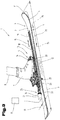
- Fig. 7 shows a further embodiment of a sports equipment 1, wherein in this embodiment, the drive device 16 is formed so that a gear 33 is coupled as needed via an intermediate gear 24 to the electric motor 21.
- the gear 33 engages in a rack 34, which is fixed to the slider 2.
- the motor axis of the electric motor 21 can - as shown - transverse to the longitudinal direction 15 of the Be aligned sliding body 2, or by the interposition of an angle or reduction gear and parallel longitudinal direction 15 extend.
- a movement can be the same as in the embodiment according to Fig. 5 expire.
- FIG. 8 is a further and possibly independent embodiment of the sports equipment 1 shown, again for like parts, the same reference numerals or component names as in the preceding FIGS. 3 to 7 be used. In order to avoid unnecessary repetition, the detailed description in the previous ones will be used FIGS. 3 to 7 referred or referred.
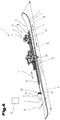
- the drive device 16 comprises a cable drive drum 35 which predetermines the movement of the binding device 6 or of the guide carriage 20 via a setting cable 36.
- at least one deflecting device 37 can be provided, by means of which the adjusting cable 36 can be deflected, so that a tension in both directions along the longitudinal direction 15 of the sliding body 2 is made possible.
- FIG. 9 is a further and possibly independent embodiment of the sports equipment 1 shown, again for like parts, the same reference numerals or component names as in the preceding FIGS. 3 to 8 be used. In order to avoid unnecessary repetition, the detailed description in the previous ones will be used FIGS. 3 to 8 referred or referred.
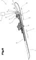
- Fig. 9 shows a further embodiment of a sports equipment 1, wherein in this embodiment, the drive device 16 includes a control cylinder 38 which is provided for active, variable-position adjustment of the binding device 6 relative to the slider 2.
- the adjusting cylinder 38 may be formed for example by a pneumatic cylinder or by a hydraulic cylinder. In this case, either the piston rod or the piston cylinder on the sliding body 2 is held fixed in position and the other part with the binding device 6 or with the guide carriage 20 coupled in order to effect an active relative displacement of the binding device 6 in the longitudinal direction 15 of the slider 2.
- FIG. 10 is a further and possibly independent embodiment of the sports equipment 1 shown, again for like parts, the same reference numerals or component names as in the preceding FIGS. 3 to 9 be used. In order to avoid unnecessary repetition, the detailed description in the previous ones will be used FIGS. 3 to 9 referred or referred.
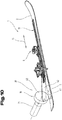
- Fig. 10 shows a further embodiment of a sports equipment 1, wherein in this case the drive device 16 comprises a crank mechanism 39, with which the binding device 6 in the longitudinal direction 15 of the slider 2 adjusted or can be actively positioned longitudinally.
- the drive device 16 comprises a crank mechanism 39, with which the binding device 6 in the longitudinal direction 15 of the slider 2 adjusted or can be actively positioned longitudinally.
- a crank disk 40 or a corresponding crank arm is fastened to the sliding body 2 via a bearing 41 and the crank disk 40 is driven by the electric motor 21.
- a connecting rod 42 is received in eccentric bearing, which is connected to a guide carriage 20 and to the binding device 6.
- the drive device 16 comprises a linear motor, wherein a first winding arrangement and / or a permanent magnet arrangement can be integrated into the guide rail 19 or into the sliding body 2, wherein the guide carriage 20 or The binding device 6 serves as a corresponding, electromagnetic rotor.
- Fig. 11 shows an embodiment of a sports equipment 1 accordingly Fig. 5 ,
- the binding device 6 is shown in a folded or pivoted up position and therefore a walking position of the binding device 6 is shown.
- the binding device 6 is rotated in a rotational angle position 43 relative to the slider 2.
- Such rotational angle positions 43 are taken in particular in the course of walking movements or step sequences.
- the binding device 6 is therefore preferably formed by a so-called touring binding, which - as known per se - defined a transverse to the longitudinal axis 15 and substantially parallel to the sliding surface 4 of the slider 2 aligned pivot axis.
- Fig. 12 shows a perspective view of a sports device 1 and two sports equipment 1 on which a user 8 is located.
- the sports equipment 1 is used in pairs, wherein a first sports equipment 1 is assigned to the left foot of the user 8 and another sports equipment 1 is assigned to the right foot of the user 8.
- the sports shoes 7 of the user 8 can be coupled and decoupled via the binding devices 6 relative to the sports equipment 1 as required.
- the user 8 transports the power supply device 17 in a backpack.
- the electrochemical energy store or the energy supply device 17 it is also possible for the electrochemical energy store or the energy supply device 17 to be arranged in a hip belt or in a jacket of the user.
- the energy supply device 17 may in this case be in the form of an electrochemical battery pack, in particular a lead gel, nickel-cadmium (NiCd), nickel-metal hydride (NiMH) or lithium-ion (Li-ion) battery.
- an electrochemical battery pack in particular a lead gel, nickel-cadmium (NiCd), nickel-metal hydride (NiMH) or lithium-ion (Li-ion) battery.
- the energy supply device 17 is designed in the form of a compressed air reservoir. According to a further possibility, it can be provided that the energy supply device 17 is a compressor or a hydraulic unit includes the necessary energy or the required medium pressure to drive a positioning cylinder 38 -. Fig. 9 - to raise.
- a control unit 44 is coupled to the power supply device 17, which controls or regulates the movement sequence or the eventual supply of the drive device 16 with drive energy.
- An input device 45 can be connected to the control unit 44, by means of which the movement speeds or movement frequencies and / or the desired travel paths of the binding device 6 relative to the sliding body 2 can be preset.
- the sports equipment 1 comprises a detection means 46, through which the control command can be given to start the sliding movement.
- This detection means 46 may be formed, for example in the form of a button, which the user actively controls or manually operated and thus initiates the movement.
- a detection means 46 ' is integrated, for example, in the binding device 6 and detects a rotational angle position 43 or the pressure on the binding device 6.
- the sports equipment 1 may be provided for use by various users.
- the adjustable pressure on the binding device 6 to activate the detection means 46 ' may be between 70% and 100%, preferably between 80% and 90% of the body weight of the user.
- the pulse for starting the movement movement can also be given by the physiological course of the walking movement, whereby the user 8 does not have to consciously initiate the movement.
- an automatic or partially automated activation and / or deactivation of the drive device 16 can be implemented by implementing a sensory detection means 46 '.
- the detection means 46 comprises an acceleration sensor.
- an acceleration sensor can detect the acceleration acting, for example, on the binding device 6 and, based on these measured values, initiate the travel movement of the drive device 16.
- the detection means 46 comprises a non-contact distance measuring means.
- This distance measuring means can be provided to detect the distance of the binding device 6 of the sports equipment 1 attached to the left foot to the binding device 6 of the sports equipment 1 mounted on the right foot and to control the drive device 16 on the basis of the current sequence of steps in the walking movement of the user 8.
- a locking device 47 can be provided, by means of which the binding device 6 can be locked along the longitudinal direction 15 at a specific position. This is of particular use in order to achieve a stable and secure hold of the user 8 on the sliding body 2 in the downhill state of the sports equipment 1.
- the user 8 takes a step forward with his right foot, pushing him in front of his left foot. During this movement, a large part of the mass of the user 8 rests on the sports equipment 1 mounted on the left foot. If the user 8 has now pushed his right foot forward in accordance with his stride length 49, he places it on the ground 12, whereby that on the right foot mounted sports equipment 1 is loaded and the user 8 can lift his left foot to push this forward. While the user 8 lifts his left foot away from the ground 12, the touring binding device 6 of the left sports device 1 pivots upwardly by a certain angular position 43 due to the physiological process, thereby facilitating walking or stepping.
- the start command is now given to the control unit 44 to start the drive movement of the drive device 16 of the right sports device 1 by the detection means 46 or 46 ' ,
- the drive device 16 is activated, whereby the binding device 6 of the mounted on the right foot sports equipment 1 is moved from its normal position 25 in an advanced position 26.
- the center of gravity of the user 8 is moved forward by the preferably adjustable amount in the direction of travel 48, whereby the step length 49 is extended or the distance traveled by the user 8 is increased.
- the user 8 sets his relieved left foot according to his stride length 49 forward until he sets off the left foot and thus the left sports equipment 1 on the ground 12.
- the left foot is in this case pushed so far forward that he is seen in the direction of travel 48 placed in front of the right foot.
- the user 8 loads the left foot and thus the left sports device with his body weight, at the same time or immediately after the right sports equipment 1 is relieved and the right binding device 6 is pivoted into a rotational position 43.
- the control device for activating the drive device 16 of the left foot mounted sports equipment 1 is triggered by the input device 45 and the detection means 46, 46 ', respectively, causing the binding device 6 of the sports equipment 1 mounted on the left foot of the user 8 from its normal position 25 moves to an advanced position 26.
- a control command is given to the drive device 16 of the sports equipment 1 mounted on the right foot by the control unit 44 or by the at least one detection means 46, 46 ', so that the latter - while it is relieved and does not rest on the base 12 - is moved from the advanced position 26 is moved back to its basic position 25.
- This return movement for example, by reversing the effective direction of the Drive energy done.
- This can be for example a double-acting cylinder, or an electric motor with two adjustable directions of rotation.
- the drive device 16 comprises a return device, which is provided for returning the binding device 6.
- a return device which is provided for returning the binding device 6.
- This may be, for example, a spring arrangement, which is biased by the movement about the travel 27 and can initiate a return movement against the direction of travel
- the binding device 6 of the right sports equipment 1 is returned to its normal position 25, so that the user 8 can set the right sports equipment 1 back on the ground 12 and again burden.
- the motion sequence just described can now begin anew and continue cyclically or acyclically.
- FIGS. 13 and 14 a top view of a user 8, each with a foot strapped sports device 1 shown.
- FIGS. 13 and 14 the same reference numerals or component names for the same parts as in the preceding FIGS. 3 to 12 used. In order to avoid unnecessary repetition, the detailed description in the previous ones will be used FIGS. 3 to 12 referred or referred.
- Fig. 13 In the illustration after Fig. 13 is the slider 2 of the sports equipment 1, which is strapped to the right foot of the user 8, as seen in the direction of travel 48 to the stride length 49 of the user 8 relative to the slider 2 of the sports equipment 1, which is strapped to the left foot of the user 8, moved.
- This shift as shown Fig. 13 can be achieved, for example, while walking with a conventional touring ski.
- the stride length 49 is the amount by which the user 8 places one foot in front of the other during the normal walking movement.
- the stride length 49 is highly dependent on the leg length of the user 8.
- the stride length 49 can also be used by a user 8 vary and, for example, depending on the nature of the substrate 12, the current physical condition of the user 8, etc.
- Fig. 14 is the slider 2 of the sports equipment 1, which is strapped to the right foot of the user 8, seen in the direction of travel 48 by an extended stride 50 relative to the slider 2 of the sports equipment 1, which is strapped to the left foot of the user 8, moved.
- the extended stride length 50 is a summed value of the stride length 49 of the user 8 and the travel 27, which the sports shoe 7 can be moved relative to the slider 2.
- the stride length 49 of the user 8 are extended by the travel 27.
- the traveling speed of the user 8 can be increased.
- the user 8 has fewer steps to take than using conventional touring skis.
- the user 8 is physically less stressed during the ascent to a mountain, using a sports device 1 according to the invention, as would be the case using conventional touring skis.
- the travel path 27 is the extent by which the binding device 6 is displaced from its basic position 25 into its advanced position 26.
- the sports equipment 1 is particularly suitable for the exercise of touring skiing or cross-country ski sports, where it can facilitate the user 8 above all the travel distances or climbs.
Landscapes
- Transmission Devices (AREA)
Claims (15)
- Article de sport (1), plus particulièrement dispositif de ski de randonnées, comprenant un corps de glissement (2) au niveau duquel est réalisé un côté inférieur (3) en tant que surface de glissement (4), un dispositif de fixation (6) disposé sur le côté supérieur (5) du corps de glissement (2), plus particulièrement une fixation de randonnée, pour la fixation amovible si nécessaire d'une chaussure de sport (7) d'un utilisateur (8), l'article de sport (1) comprenant un dispositif à palier (13) à l'aide duquel le dispositif de fixation (6), plus particulièrement une partie de support de chaussure (14) du dispositif de fixation (6), est maintenu de manière réglable relativement au corps de glissement (2) le long de sa direction longitudinale (15),
caractérisé en ce que
un dispositif d'entraînement (16), pouvant être relié à un dispositif d'alimentation en énergie (17), est conçu pour faire coulisser le dispositif de fixation (6) de manière active et de manière couplée pour un processus de marche de l'utilisateur (8) dans la direction longitudinale (15) du corps de glissement (2). - Article de sport selon la revendication 1, caractérisé en ce que le dispositif à palier (13) comprend un guidage linéaire, plus particulièrement, un guidage à rail profilé (18) ainsi qu'un guidage à glissement linéaire ou un guidage à bille linéaire.
- Article de sport selon la revendication 2, caractérisé en ce qu'un rail de guidage (19) du guidage linéaire est fixé au corps de glissement (2) ou est intégré dans celui-ci et au moins un chariot de guidage (20) correspondant avec le rail de guidage (19) est fixé au dispositif de fixation (6) ou est intégré dans celui-ci.
- Article de sport selon l'une des revendications 1 à 3, caractérisé en ce que le dispositif d'entraînement (16) comprend un moteur électrique (21) à l'aide duquel le dispositif de fixation (6) peut coulisser par rapport au corps de glissement (2).
- Article de sport selon la revendication 4, caractérisé en ce que le moteur électrique (21) est conçu comme un moteur à broche ou, au choix, est couplé, par l'intermédiaire d'une transmission (24), à une broche de réglage (22).
- Article de sport selon la revendication 4, caractérisé en ce que le moteur électrique (21) est, au choix, couplé par l'intermédiaire d'une transmission (24) à une roue dentée (33) qui s'emboîte dans une crémaillère (34) correspondante.
- Article de sport selon la revendication 4, caractérisé en ce que le moteur électrique (21) est, au choix, couplé par l'intermédiaire d'une transmission (24) à un tambour d'entraînement par câble (35).
- Article de sport selon l'une des revendications 1 à 3, caractérisé en ce que le dispositif d'entraînement (16) comprend un vérin de réglage (38), à savoir un vérin pneumatique ou un vérin hydraulique, à l'aide duquel le dispositif de fixation (6) peut coulisser par rapport au corps de glissement (2).
- Article de sport selon l'une des revendications 1 à 8, caractérisé en ce qu'une unité de commande électrotechnique (44) est reliée avec le dispositif d'entraînement (16) et est conçue pour le contrôle du dispositif d'entraînement (16), cette unité de commande (44) comprenant un dispositif d'entrée numérique (45) ou comprend un potentiomètre à l'aide duquel une vitesse de déplacement, une durée de mise en marche, des moments de commutation et/ou une course de déplacement du dispositif d'entraînement (16) peut être prédéterminé ou est réglable de manière variable.
- Article de sport selon la revendication 9, caractérisé en ce que l'unité de commande (44) est relié avec au moins un moyen de détection (46, 46'), par exemple un contact de commutation ou un capteur électrotechnique, pour la détection d'une instruction d'activation pour le dispositif d'entraînement (16).
- Article de sport selon la revendication 10, caractérisé en ce que l'au moins un moyen de détection (46, 46') est conçu pour la détection d'une instruction de commande initiée activement ou consciente par un utilisateur (8) et/ou pour la détection d'un état de déplacement dû au processus de déplacement physiologique, par exemple d'une position angulaire de rotation (43) prédéterminée du dispositif de fixation (6) par rapport au corps de glissement (2) ou d'une sollicitation en pression par rapport au corps de glissement (2), et en ce que le dispositif d'entraînement (16) est commandé en fonction des états de détection de l'au moins un moyen de détection (46, 46').
- Article de sport selon l'une des revendications 1 à 11, caractérisé en ce qu'une course de déplacement (27) du dispositif de fixation (6) par rapport au corps de glissement (2) est entre 40 mm et 600 mm, plus particulièrement entre 200 mm et 500 mm, de préférence entre 250 mm et 350 mm.
- Article de sport selon la revendication 4 ou 6, caractérisé en ce que le moteur électrique (21) et l'éventuelle transmission (24) sont logés dans une roue creuse (28), une enveloppe externe de la roue creuse (28) comprenant une denture circulaire (29).
- Article de sport selon l'une des revendications 3 à 13, caractérisé en ce que le rail de guidage (19) présente une denture (30), dans lequel la roue dentée (33) ou la denture circulaire (29) de la roue creuse (28) s'engrène.
- Article de sport selon l'une des revendications 1 à 14, caractérisé en ce que le dispositif d'entraînement (16) est couplé en mouvement avec le dispositif de fixation (6) et peut coulisser en même temps que le dispositif de fixation (6) par rapport au corps de glissement (2).
Applications Claiming Priority (3)
| Application Number | Priority Date | Filing Date | Title |
|---|---|---|---|
| AT5252013A AT514478B1 (de) | 2013-06-26 | 2013-06-26 | Motorische Tourenskiaufstiegshilfe |
| ATA50298/2014A AT515766B1 (de) | 2014-04-23 | 2014-04-23 | Sportgerät |
| PCT/AT2014/050144 WO2014205472A1 (fr) | 2013-06-26 | 2014-06-25 | Appareil de sport, notamment aide motorisée à la montée pour ski de randonnée |
Publications (2)
| Publication Number | Publication Date |
|---|---|
| EP3013443A1 EP3013443A1 (fr) | 2016-05-04 |
| EP3013443B1 true EP3013443B1 (fr) | 2017-05-17 |
Family
ID=51302862
Family Applications (1)
| Application Number | Title | Priority Date | Filing Date |
|---|---|---|---|
| EP14750425.2A Active EP3013443B1 (fr) | 2013-06-26 | 2014-06-25 | Appareil de sport, notamment aide motorisée à la montée pour ski de randonnée |
Country Status (2)
| Country | Link |
|---|---|
| EP (1) | EP3013443B1 (fr) |
| WO (1) | WO2014205472A1 (fr) |
Cited By (1)
| Publication number | Priority date | Publication date | Assignee | Title |
|---|---|---|---|---|
| US11065528B2 (en) | 2018-09-18 | 2021-07-20 | Stephen S. Daniell | Thrust-responsive surface material for skis |
Families Citing this family (7)
| Publication number | Priority date | Publication date | Assignee | Title |
|---|---|---|---|---|
| GB2539386A (en) * | 2015-06-03 | 2016-12-21 | Artemev Timur | Transportation device |
| NO340839B1 (no) * | 2015-11-30 | 2017-06-26 | Rottefella As | System for valgfri dynamisk posisjonering av en skibinding på en ski |
| SI3238792T1 (sl) * | 2016-04-28 | 2019-07-31 | Gogreeen S.a.s. di Rossi Maurizio | Priprava za pomoč pri koraku pri opremi za hojo |
| NO342933B1 (no) * | 2017-05-30 | 2018-09-03 | Rottefella As | Festemekanisme for et låseorgan som skal festes til en monteringsplate på en langrennsski |
| WO2019010739A1 (fr) * | 2017-07-12 | 2019-01-17 | 北京孙寅贵绿色科技研究院有限公司 | Dispositif de fixation arrière intelligent d'un ski, ski et équipement de ski |
| IT202200002609A1 (it) * | 2022-02-14 | 2023-08-14 | Gogreeen S A S Di Rossi Maurizio | Sistema per sciare in posizione seduta |
| EP4670804A1 (fr) * | 2023-02-20 | 2025-12-31 | Coretti Sanchez, Oier | Dispositif d'assistance électrique pour le ski |
Family Cites Families (12)
| Publication number | Priority date | Publication date | Assignee | Title |
|---|---|---|---|---|
| DE247482C (fr) | ||||
| DE649153C (de) | 1934-03-27 | 1937-08-16 | Margarethe Katz Geb Phenn | Antriebsvorrichtung fuer Schneeschuhe |
| US2625229A (en) * | 1950-05-19 | 1953-01-13 | Stanley Van Voorhees | Power-driven ski |
| FR2296443A1 (fr) * | 1975-01-03 | 1976-07-30 | Zuber Didier | Remonte-pente individuel et autonome pour skieur |
| DE3544688A1 (de) | 1985-12-18 | 1987-06-19 | Matthias Stolz | Vorrichtung zum motorischen antrieb eines sportlers |
| FR2604367B1 (fr) * | 1986-09-26 | 1988-12-23 | Imberteche Rene | Dispositif d'assistance electrique aux differentes fonctions d'un ski universel |
| DE3644561A1 (de) | 1986-12-27 | 1988-06-23 | Paul Huber | Fahrwerk mit fuehrung einer raupenkette zur uebertragung von motorkraft auf ski |
| AT403659B (de) | 1995-03-02 | 1998-04-27 | Crepaz Friedrich | Motorisch angetriebene aufstiegshilfe für tourenschiläufer |
| DE10037503C2 (de) * | 2000-08-01 | 2002-10-17 | Werner Dorsch | An einem Gleitgerät verankerbare Halteeinrichtung für einen Schuh |
| US7104564B2 (en) * | 2000-08-10 | 2006-09-12 | Martin Ralph M | Backwards release ski binding |
| US7159891B1 (en) * | 2003-11-26 | 2007-01-09 | Dale Niggemann | All-terrain ski |
| DE102005043810A1 (de) * | 2005-09-13 | 2007-03-15 | Marker Deutschland Gmbh | Verstelleinrichtung einer Bindung für Schneegleitbretter |
-
2014
- 2014-06-25 EP EP14750425.2A patent/EP3013443B1/fr active Active
- 2014-06-25 WO PCT/AT2014/050144 patent/WO2014205472A1/fr not_active Ceased
Cited By (2)
| Publication number | Priority date | Publication date | Assignee | Title |
|---|---|---|---|---|
| US11065528B2 (en) | 2018-09-18 | 2021-07-20 | Stephen S. Daniell | Thrust-responsive surface material for skis |
| US11511178B2 (en) | 2018-09-18 | 2022-11-29 | Stephen S. Daniell | Thrust-responsive surface material for skis |
Also Published As
| Publication number | Publication date |
|---|---|
| EP3013443A1 (fr) | 2016-05-04 |
| WO2014205472A1 (fr) | 2014-12-31 |
Similar Documents
| Publication | Publication Date | Title |
|---|---|---|
| EP3013443B1 (fr) | Appareil de sport, notamment aide motorisée à la montée pour ski de randonnée | |
| EP3148658B1 (fr) | Engin de sport avec corps de glisse et motorisation pour une bande continue | |
| DE602006000962T2 (de) | Beweglicher Roboter | |
| DE2919494C2 (de) | Trainingsgerät mit zwei von einem Ständer getragenen Tretkurbeln | |
| DE69427773T2 (de) | Laufband mit zwei in entgegengesetzter richtung laufenden bändern | |
| EP2451423B1 (fr) | Entraînement électrique destiné à un déambulateur à roulettes | |
| DE19745153C2 (de) | Transportvorrichtung | |
| EP1129923B1 (fr) | Dispositif de transport | |
| DE202009009366U1 (de) | Heimtierlaufband | |
| DE2454976A1 (de) | Apparat zum imitierten skilaufen | |
| EP1970037A1 (fr) | Véhicule de transport d'un fauteuil roulant | |
| EP2281615B1 (fr) | Aide à la montée, fixation de ski de fond et équipement de ski | |
| DE3131049C2 (de) | Antrieb für einen Rollschuh | |
| DE102009036245A1 (de) | Gleitbrettausrüstung und Bindung für ein Gleitbrett | |
| AT515766B1 (de) | Sportgerät | |
| WO2018141890A1 (fr) | Ski et système de ski | |
| DE102009014326B4 (de) | Transportvorrichtung | |
| DE102009052846B4 (de) | Inline-Skater | |
| DE69207890T2 (de) | Fabrikationsverfahren eines Rollbretts mit körperlichen Antrieb | |
| AT514478B1 (de) | Motorische Tourenskiaufstiegshilfe | |
| AT516024B1 (de) | Sportgerät, insbesondere Tourenskianordnung | |
| EP4371625A1 (fr) | Dispositif d'entraînement, dispositif de déplacement et procédé de déplacement d'un dispositif de mouvement | |
| DE202023103573U1 (de) | Zweidimensionales Laufband | |
| CH716537A2 (de) | Hilfsantrieb für Langlaufskier mit elektrischem Antrieb. | |
| AT518074A4 (de) | Skisportgerät und Verfahren zum Betreiben desselben |
Legal Events
| Date | Code | Title | Description |
|---|---|---|---|
| PUAI | Public reference made under article 153(3) epc to a published international application that has entered the european phase |
Free format text: ORIGINAL CODE: 0009012 |
|
| 17P | Request for examination filed |
Effective date: 20160127 |
|
| AK | Designated contracting states |
Kind code of ref document: A1 Designated state(s): AL AT BE BG CH CY CZ DE DK EE ES FI FR GB GR HR HU IE IS IT LI LT LU LV MC MK MT NL NO PL PT RO RS SE SI SK SM TR |
|
| AX | Request for extension of the european patent |
Extension state: BA ME |
|
| DAX | Request for extension of the european patent (deleted) | ||
| GRAP | Despatch of communication of intention to grant a patent |
Free format text: ORIGINAL CODE: EPIDOSNIGR1 |
|
| INTG | Intention to grant announced |
Effective date: 20170104 |
|
| RIN1 | Information on inventor provided before grant (corrected) |
Inventor name: HOLZER, HELMUT Inventor name: RIESENHUBER, THOMAS Inventor name: SCHWARZENBACHER, RUDOLF |
|
| GRAS | Grant fee paid |
Free format text: ORIGINAL CODE: EPIDOSNIGR3 |
|
| GRAA | (expected) grant |
Free format text: ORIGINAL CODE: 0009210 |
|
| AK | Designated contracting states |
Kind code of ref document: B1 Designated state(s): AL AT BE BG CH CY CZ DE DK EE ES FI FR GB GR HR HU IE IS IT LI LT LU LV MC MK MT NL NO PL PT RO RS SE SI SK SM TR |
|
| REG | Reference to a national code |
Ref country code: GB Ref legal event code: FG4D Free format text: NOT ENGLISH |
|
| REG | Reference to a national code |
Ref country code: CH Ref legal event code: EP |
|
| REG | Reference to a national code |
Ref country code: IE Ref legal event code: FG4D Free format text: LANGUAGE OF EP DOCUMENT: GERMAN |
|
| REG | Reference to a national code |
Ref country code: AT Ref legal event code: REF Ref document number: 893944 Country of ref document: AT Kind code of ref document: T Effective date: 20170615 |
|
| REG | Reference to a national code |
Ref country code: DE Ref legal event code: R082 Ref document number: 502014003902 Country of ref document: DE Representative=s name: ABP BURGER RECHTSANWALTSGESELLSCHAFT MBH, DE Ref country code: DE Ref legal event code: R082 Ref document number: 502014003902 Country of ref document: DE Representative=s name: ANWAELTE BURGER UND PARTNER RECHTSANWALTSKANZL, AT Ref country code: FR Ref legal event code: PLFP Year of fee payment: 4 Ref country code: DE Ref legal event code: R082 Ref document number: 502014003902 Country of ref document: DE Representative=s name: FUNK, ALEXANDER, M.SC. (SIU), DR., DE |
|
| REG | Reference to a national code |
Ref country code: DE Ref legal event code: R096 Ref document number: 502014003902 Country of ref document: DE |
|
| REG | Reference to a national code |
Ref country code: CH Ref legal event code: NV Representative=s name: ABP PATENT NETWORK AG, CH |
|
| REG | Reference to a national code |
Ref country code: DE Ref legal event code: R082 Ref document number: 502014003902 Country of ref document: DE Representative=s name: ABP BURGER RECHTSANWALTSGESELLSCHAFT MBH, DE Ref country code: DE Ref legal event code: R082 Ref document number: 502014003902 Country of ref document: DE Representative=s name: FUNK, ALEXANDER, M.SC. (SIU), DR., DE |
|
| REG | Reference to a national code |
Ref country code: NL Ref legal event code: MP Effective date: 20170517 |
|
| REG | Reference to a national code |
Ref country code: LT Ref legal event code: MG4D |
|
| PG25 | Lapsed in a contracting state [announced via postgrant information from national office to epo] |
Ref country code: HR Free format text: LAPSE BECAUSE OF FAILURE TO SUBMIT A TRANSLATION OF THE DESCRIPTION OR TO PAY THE FEE WITHIN THE PRESCRIBED TIME-LIMIT Effective date: 20170517 Ref country code: NO Free format text: LAPSE BECAUSE OF FAILURE TO SUBMIT A TRANSLATION OF THE DESCRIPTION OR TO PAY THE FEE WITHIN THE PRESCRIBED TIME-LIMIT Effective date: 20170817 Ref country code: FI Free format text: LAPSE BECAUSE OF FAILURE TO SUBMIT A TRANSLATION OF THE DESCRIPTION OR TO PAY THE FEE WITHIN THE PRESCRIBED TIME-LIMIT Effective date: 20170517 Ref country code: GR Free format text: LAPSE BECAUSE OF FAILURE TO SUBMIT A TRANSLATION OF THE DESCRIPTION OR TO PAY THE FEE WITHIN THE PRESCRIBED TIME-LIMIT Effective date: 20170818 Ref country code: LT Free format text: LAPSE BECAUSE OF FAILURE TO SUBMIT A TRANSLATION OF THE DESCRIPTION OR TO PAY THE FEE WITHIN THE PRESCRIBED TIME-LIMIT Effective date: 20170517 Ref country code: ES Free format text: LAPSE BECAUSE OF FAILURE TO SUBMIT A TRANSLATION OF THE DESCRIPTION OR TO PAY THE FEE WITHIN THE PRESCRIBED TIME-LIMIT Effective date: 20170517 |
|
| PG25 | Lapsed in a contracting state [announced via postgrant information from national office to epo] |
Ref country code: NL Free format text: LAPSE BECAUSE OF FAILURE TO SUBMIT A TRANSLATION OF THE DESCRIPTION OR TO PAY THE FEE WITHIN THE PRESCRIBED TIME-LIMIT Effective date: 20170517 Ref country code: RS Free format text: LAPSE BECAUSE OF FAILURE TO SUBMIT A TRANSLATION OF THE DESCRIPTION OR TO PAY THE FEE WITHIN THE PRESCRIBED TIME-LIMIT Effective date: 20170517 Ref country code: IS Free format text: LAPSE BECAUSE OF FAILURE TO SUBMIT A TRANSLATION OF THE DESCRIPTION OR TO PAY THE FEE WITHIN THE PRESCRIBED TIME-LIMIT Effective date: 20170917 Ref country code: LV Free format text: LAPSE BECAUSE OF FAILURE TO SUBMIT A TRANSLATION OF THE DESCRIPTION OR TO PAY THE FEE WITHIN THE PRESCRIBED TIME-LIMIT Effective date: 20170517 Ref country code: SE Free format text: LAPSE BECAUSE OF FAILURE TO SUBMIT A TRANSLATION OF THE DESCRIPTION OR TO PAY THE FEE WITHIN THE PRESCRIBED TIME-LIMIT Effective date: 20170517 Ref country code: BG Free format text: LAPSE BECAUSE OF FAILURE TO SUBMIT A TRANSLATION OF THE DESCRIPTION OR TO PAY THE FEE WITHIN THE PRESCRIBED TIME-LIMIT Effective date: 20170817 Ref country code: PL Free format text: LAPSE BECAUSE OF FAILURE TO SUBMIT A TRANSLATION OF THE DESCRIPTION OR TO PAY THE FEE WITHIN THE PRESCRIBED TIME-LIMIT Effective date: 20170517 |
|
| PG25 | Lapsed in a contracting state [announced via postgrant information from national office to epo] |
Ref country code: EE Free format text: LAPSE BECAUSE OF FAILURE TO SUBMIT A TRANSLATION OF THE DESCRIPTION OR TO PAY THE FEE WITHIN THE PRESCRIBED TIME-LIMIT Effective date: 20170517 Ref country code: SK Free format text: LAPSE BECAUSE OF FAILURE TO SUBMIT A TRANSLATION OF THE DESCRIPTION OR TO PAY THE FEE WITHIN THE PRESCRIBED TIME-LIMIT Effective date: 20170517 Ref country code: DK Free format text: LAPSE BECAUSE OF FAILURE TO SUBMIT A TRANSLATION OF THE DESCRIPTION OR TO PAY THE FEE WITHIN THE PRESCRIBED TIME-LIMIT Effective date: 20170517 Ref country code: CZ Free format text: LAPSE BECAUSE OF FAILURE TO SUBMIT A TRANSLATION OF THE DESCRIPTION OR TO PAY THE FEE WITHIN THE PRESCRIBED TIME-LIMIT Effective date: 20170517 Ref country code: RO Free format text: LAPSE BECAUSE OF FAILURE TO SUBMIT A TRANSLATION OF THE DESCRIPTION OR TO PAY THE FEE WITHIN THE PRESCRIBED TIME-LIMIT Effective date: 20170517 |
|
| REG | Reference to a national code |
Ref country code: DE Ref legal event code: R097 Ref document number: 502014003902 Country of ref document: DE |
|
| PG25 | Lapsed in a contracting state [announced via postgrant information from national office to epo] |
Ref country code: SM Free format text: LAPSE BECAUSE OF FAILURE TO SUBMIT A TRANSLATION OF THE DESCRIPTION OR TO PAY THE FEE WITHIN THE PRESCRIBED TIME-LIMIT Effective date: 20170517 Ref country code: IT Free format text: LAPSE BECAUSE OF FAILURE TO SUBMIT A TRANSLATION OF THE DESCRIPTION OR TO PAY THE FEE WITHIN THE PRESCRIBED TIME-LIMIT Effective date: 20170517 |
|
| REG | Reference to a national code |
Ref country code: IE Ref legal event code: MM4A |
|
| PLBE | No opposition filed within time limit |
Free format text: ORIGINAL CODE: 0009261 |
|
| STAA | Information on the status of an ep patent application or granted ep patent |
Free format text: STATUS: NO OPPOSITION FILED WITHIN TIME LIMIT |
|
| 26N | No opposition filed |
Effective date: 20180220 |
|
| PG25 | Lapsed in a contracting state [announced via postgrant information from national office to epo] |
Ref country code: LU Free format text: LAPSE BECAUSE OF NON-PAYMENT OF DUE FEES Effective date: 20170625 Ref country code: IE Free format text: LAPSE BECAUSE OF NON-PAYMENT OF DUE FEES Effective date: 20170625 |
|
| REG | Reference to a national code |
Ref country code: BE Ref legal event code: MM Effective date: 20170630 |
|
| REG | Reference to a national code |
Ref country code: FR Ref legal event code: PLFP Year of fee payment: 5 |
|
| PG25 | Lapsed in a contracting state [announced via postgrant information from national office to epo] |
Ref country code: SI Free format text: LAPSE BECAUSE OF FAILURE TO SUBMIT A TRANSLATION OF THE DESCRIPTION OR TO PAY THE FEE WITHIN THE PRESCRIBED TIME-LIMIT Effective date: 20170517 |
|
| PG25 | Lapsed in a contracting state [announced via postgrant information from national office to epo] |
Ref country code: BE Free format text: LAPSE BECAUSE OF NON-PAYMENT OF DUE FEES Effective date: 20170630 |
|
| PG25 | Lapsed in a contracting state [announced via postgrant information from national office to epo] |
Ref country code: MT Free format text: LAPSE BECAUSE OF FAILURE TO SUBMIT A TRANSLATION OF THE DESCRIPTION OR TO PAY THE FEE WITHIN THE PRESCRIBED TIME-LIMIT Effective date: 20170517 |
|
| GBPC | Gb: european patent ceased through non-payment of renewal fee |
Effective date: 20180625 |
|
| PG25 | Lapsed in a contracting state [announced via postgrant information from national office to epo] |
Ref country code: GB Free format text: LAPSE BECAUSE OF NON-PAYMENT OF DUE FEES Effective date: 20180625 |
|
| REG | Reference to a national code |
Ref country code: DE Ref legal event code: R082 Ref document number: 502014003902 Country of ref document: DE Representative=s name: ABP BURGER RECHTSANWALTSGESELLSCHAFT MBH, DE |
|
| PG25 | Lapsed in a contracting state [announced via postgrant information from national office to epo] |
Ref country code: MC Free format text: LAPSE BECAUSE OF FAILURE TO SUBMIT A TRANSLATION OF THE DESCRIPTION OR TO PAY THE FEE WITHIN THE PRESCRIBED TIME-LIMIT Effective date: 20170517 Ref country code: HU Free format text: LAPSE BECAUSE OF FAILURE TO SUBMIT A TRANSLATION OF THE DESCRIPTION OR TO PAY THE FEE WITHIN THE PRESCRIBED TIME-LIMIT; INVALID AB INITIO Effective date: 20140625 |
|
| PG25 | Lapsed in a contracting state [announced via postgrant information from national office to epo] |
Ref country code: CY Free format text: LAPSE BECAUSE OF FAILURE TO SUBMIT A TRANSLATION OF THE DESCRIPTION OR TO PAY THE FEE WITHIN THE PRESCRIBED TIME-LIMIT Effective date: 20170517 |
|
| PG25 | Lapsed in a contracting state [announced via postgrant information from national office to epo] |
Ref country code: MK Free format text: LAPSE BECAUSE OF FAILURE TO SUBMIT A TRANSLATION OF THE DESCRIPTION OR TO PAY THE FEE WITHIN THE PRESCRIBED TIME-LIMIT Effective date: 20170517 |
|
| PG25 | Lapsed in a contracting state [announced via postgrant information from national office to epo] |
Ref country code: TR Free format text: LAPSE BECAUSE OF FAILURE TO SUBMIT A TRANSLATION OF THE DESCRIPTION OR TO PAY THE FEE WITHIN THE PRESCRIBED TIME-LIMIT Effective date: 20170517 |
|
| PG25 | Lapsed in a contracting state [announced via postgrant information from national office to epo] |
Ref country code: PT Free format text: LAPSE BECAUSE OF FAILURE TO SUBMIT A TRANSLATION OF THE DESCRIPTION OR TO PAY THE FEE WITHIN THE PRESCRIBED TIME-LIMIT Effective date: 20170517 |
|
| PG25 | Lapsed in a contracting state [announced via postgrant information from national office to epo] |
Ref country code: AL Free format text: LAPSE BECAUSE OF FAILURE TO SUBMIT A TRANSLATION OF THE DESCRIPTION OR TO PAY THE FEE WITHIN THE PRESCRIBED TIME-LIMIT Effective date: 20170517 |
|
| P01 | Opt-out of the competence of the unified patent court (upc) registered |
Effective date: 20230529 |
|
| PGFP | Annual fee paid to national office [announced via postgrant information from national office to epo] |
Ref country code: DE Payment date: 20250402 Year of fee payment: 12 |
|
| PGFP | Annual fee paid to national office [announced via postgrant information from national office to epo] |
Ref country code: FR Payment date: 20250508 Year of fee payment: 12 |
|
| PGFP | Annual fee paid to national office [announced via postgrant information from national office to epo] |
Ref country code: AT Payment date: 20250528 Year of fee payment: 12 |
|
| PGFP | Annual fee paid to national office [announced via postgrant information from national office to epo] |
Ref country code: CH Payment date: 20250701 Year of fee payment: 12 |