EP3020568A1 - Verfahren zum befestigen eines schmuckgegenstands und schmuckgegenstand - Google Patents
Verfahren zum befestigen eines schmuckgegenstands und schmuckgegenstand Download PDFInfo
- Publication number
- EP3020568A1 EP3020568A1 EP14822312.6A EP14822312A EP3020568A1 EP 3020568 A1 EP3020568 A1 EP 3020568A1 EP 14822312 A EP14822312 A EP 14822312A EP 3020568 A1 EP3020568 A1 EP 3020568A1
- Authority
- EP
- European Patent Office
- Prior art keywords
- affixing
- film
- decorated
- decorative object
- decorative
- Prior art date
- Legal status (The legal status is an assumption and is not a legal conclusion. Google has not performed a legal analysis and makes no representation as to the accuracy of the status listed.)
- Granted
Links
- 238000000034 method Methods 0.000 title claims abstract description 49
- 239000012530 fluid Substances 0.000 claims abstract description 27
- 230000001603 reducing effect Effects 0.000 claims description 28
- 230000003746 surface roughness Effects 0.000 claims description 13
- 238000003825 pressing Methods 0.000 abstract 1
- 238000010586 diagram Methods 0.000 description 26
- 239000000843 powder Substances 0.000 description 5
- 238000012856 packing Methods 0.000 description 4
- 230000037303 wrinkles Effects 0.000 description 4
- 239000000463 material Substances 0.000 description 3
- 239000002245 particle Substances 0.000 description 3
- XEEYBQQBJWHFJM-UHFFFAOYSA-N Iron Chemical compound [Fe] XEEYBQQBJWHFJM-UHFFFAOYSA-N 0.000 description 2
- 239000011248 coating agent Substances 0.000 description 2
- 238000000576 coating method Methods 0.000 description 2
- 238000004891 communication Methods 0.000 description 2
- 230000005611 electricity Effects 0.000 description 2
- 230000005389 magnetism Effects 0.000 description 2
- 230000000717 retained effect Effects 0.000 description 2
- 230000003068 static effect Effects 0.000 description 2
- 238000013459 approach Methods 0.000 description 1
- 239000000470 constituent Substances 0.000 description 1
- 230000007423 decrease Effects 0.000 description 1
- 230000006866 deterioration Effects 0.000 description 1
- 230000012447 hatching Effects 0.000 description 1
- 229910052500 inorganic mineral Inorganic materials 0.000 description 1
- 229910052742 iron Inorganic materials 0.000 description 1
- 239000000696 magnetic material Substances 0.000 description 1
- 239000011707 mineral Substances 0.000 description 1
- 238000006386 neutralization reaction Methods 0.000 description 1
- 229920001296 polysiloxane Polymers 0.000 description 1
- 239000000454 talc Substances 0.000 description 1
- 229910052623 talc Inorganic materials 0.000 description 1
Images





Classifications
-
- B—PERFORMING OPERATIONS; TRANSPORTING
- B44—DECORATIVE ARTS
- B44C—PRODUCING DECORATIVE EFFECTS; MOSAICS; TARSIA WORK; PAPERHANGING
- B44C1/00—Processes, not specifically provided for elsewhere, for producing decorative surface effects
- B44C1/18—Applying ornamental structures, e.g. shaped bodies consisting of plastic material
-
- B—PERFORMING OPERATIONS; TRANSPORTING
- B30—PRESSES
- B30B—PRESSES IN GENERAL
- B30B5/00—Presses characterised by the use of pressing means other than those mentioned in the preceding groups
- B30B5/02—Presses characterised by the use of pressing means other than those mentioned in the preceding groups wherein the pressing means is in the form of a flexible element, e.g. diaphragm, urged by fluid pressure
-
- B—PERFORMING OPERATIONS; TRANSPORTING
- B44—DECORATIVE ARTS
- B44C—PRODUCING DECORATIVE EFFECTS; MOSAICS; TARSIA WORK; PAPERHANGING
- B44C1/00—Processes, not specifically provided for elsewhere, for producing decorative surface effects
- B44C1/10—Applying flat materials, e.g. leaflets, pieces of fabrics
-
- B—PERFORMING OPERATIONS; TRANSPORTING
- B44—DECORATIVE ARTS
- B44C—PRODUCING DECORATIVE EFFECTS; MOSAICS; TARSIA WORK; PAPERHANGING
- B44C3/00—Processes, not specifically provided for elsewhere, for producing ornamental structures
- B44C3/04—Modelling plastic materials, e.g. clay
- B44C3/046—Modelling plastic materials, e.g. clay using a modelling surface, e.g. plate
- B44C3/048—Modelling plastic materials, e.g. clay using a modelling surface, e.g. plate applying an additional decorative element, e.g. picture
-
- B—PERFORMING OPERATIONS; TRANSPORTING
- B44—DECORATIVE ARTS
- B44C—PRODUCING DECORATIVE EFFECTS; MOSAICS; TARSIA WORK; PAPERHANGING
- B44C1/00—Processes, not specifically provided for elsewhere, for producing decorative surface effects
- B44C1/16—Processes, not specifically provided for elsewhere, for producing decorative surface effects for applying transfer pictures or the like
- B44C1/165—Processes, not specifically provided for elsewhere, for producing decorative surface effects for applying transfer pictures or the like for decalcomanias; sheet material therefor
- B44C1/17—Dry transfer
Definitions
- the present invention relates to a decorative object and a method of affixing a decorative object, in which the decorative object is affixed to an object that is to be decorated.
- the affixing surface of the object to be decorated has a complex three-dimensional shape in portions thereof, then in relation to such portions, wrinkles tend to enter into the decorative sheet, and there is a need to extend or stretch the decorative sheet.
- cases are known to occur in which excessive stretching results in excess of the affixing range, and patterns, characters, symbols, etc., that are drawn on the decorative sheet become distorted.
- the present invention has the object of providing a decorative object and a method of affixing a decorative object, which enhances the accuracy or reliability with which a decorative sheet can be affixed, by controlling an amount of stretching of the decorative sheet.
- the present invention is characterized by a method of affixing a decorative object in which the decorative object is configured to be affixed to an object to be decorated, comprising a holding force adjusting step of causing a holding force of the decorative object with respect to an affixing film to differ locally, a step of attaching the decorative object to a surface on a side of the affixing film that faces toward the object to be decorated, a step of placing the affixing film in facing relation to the object to be decorated, and a step of, after air inside a cover member and a vessel has been reduced in pressure, introducing a fluid into a space between the affixing film and the cover member, to thereby pressure bond and affix the decorative object on the object to be decorated.
- the present invention further is characterized by method of affixing a decorative object in which the decorative object is configured to be affixed to an object to be decorated, comprising a holding force adjusting step of causing a holding force of the decorative object with respect to an affixing film to differ locally, a step of attaching the decorative object to a surface on a side of the affixing film that faces toward the object to be decorated, a step of placing the affixing film in covering relation to the object to be decorated, and a step of reducing pressure of a space between the affixing film and the object to be decorated, to thereby pressure bond and affix the decorative object on the object to be decorated.
- the holding force of the decorative object with respect to the affixing film is made to differ locally, by locally changing a contact area between the affixing film and the decorative object.
- the holding force of the decorative object with respect to the affixing film is made to differ locally, by locally changing a charge amount between the affixing film and the decorative object.
- the holding force of the decorative object with respect to the affixing film is made to differ locally, by locally changing a magnetic force between the affixing film and the decorative object.
- the present invention is further characterized by a decorative object to be affixed to an object to be decorated using an affixing film, wherein on the decorative object, a holding force of the decorative object with respect to the affixing film to which the decorative object is attached is configured to differ locally.
- the holding force of the decorative object with respect to the affixing film is configured to differ locally, by a surface roughness of a surface of the decorative object that is attached to the affixing film being changed locally.
- the holding force of the decorative object with respect to the affixing film is configured to differ locally, by a charge amount of the decorative object being changed locally.
- the affixing film includes a magnet, and the holding force of the decorative object with respect to the affixing film is configured to differ locally, by an amount of magnetic bodies that are kneaded into the decorative object being changed locally.
- the charge amount of the decorative object with respect to the affixing film is made to differ locally, the amount of stretching of the decorative object in relation to the amount of stretching of the affixing film can be controlled locally.
- the possibility for wrinkles to occur in the decorative object can be controlled, while in addition, distortion of characters or patterns, etc., that are drawn on the decorative object can be prevented.
- FIG. 1 is a structural diagram of an affixing apparatus 10.
- the affixing apparatus 10 includes a vessel 14 that accommodates an object to be decorated 12 (see FIG. 2 ) and which opens upwardly, a cover member 16 that covers an opening of the vessel 14 from above, a raising and lowering mechanism 18 for raising and lowering the cover member 16, a pressure reducing mechanism 20 for reducing the pressure in the interior of the vessel 14 and the cover member 16, and a control unit 22 for controlling the raising and lowering mechanism 18 and the pressure reducing mechanism 20.
- the raising and lowering mechanism 18 includes a frame 24, a plurality of support posts 26 that support the frame 24, and a cylinder 28 disposed on an upper surface side of the frame 24.
- a rod 30 of the cylinder 28 is connected to an upper surface of the cover member 16.
- the pressure reducing mechanism 20 includes a cover member side evacuating mechanism 32 for evacuating a fluid (a fluid such as air or the like) on the side of the cover member 16, a vessel side evacuating mechanism 34 for evacuating a fluid (a fluid such as air or the like) on the side of the vessel 14, a cover member pressure reducing pump 36, and a vessel pressure reducing pump 38.
- the cover member side evacuating mechanism 32 is connected to the cover member pressure reducing pump 36
- the vessel side evacuating mechanism 34 is connected to the vessel pressure reducing pump 38.
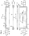
- FIG. 2 is an enlarged cross-sectional view of an essential part of the affixing apparatus 10.
- an affixing film 52 is disposed, with a decorative sheet 50 as a decorative object being attached on a lower surface of the affixing film 52.
- the affixing film 52 is retained by a film holding frame 54.
- the film holding frame 54 is a plate-shaped jig that supports an edge of the affixing film 52, and includes an opening 56 on an inner side thereof.
- the film holding frame 54 includes an upper holding frame 54a and a lower holding frame 54b, and retains the affixing film 52 by the upper holding frame 54a and the lower holding frame 54b sandwiching the affixing film 52 from above and below. It goes without saying that the openings 56 are disposed respectively in the upper holding frame 54a and the lower holding frame 54b.
- the film holding frame 54 is retained by a lower opening surface 16a of the cover member 16 and an upper opening surface 14a of the vessel 14.
- Reference numeral 57 indicates a frame-shaped packing that seals the film holding frame 54 and the upper opening surface 14a of the vessel 14.
- the cover member side evacuating mechanism 32 which is a portion of the pressure reducing mechanism 20 that evacuates a fluid such as air or the like that exists in a space 58 formed by the affixing film 52 and the cover member 16, and a cover member side introduction valve 60 that introduces a fluid (a fluid such as air or the like) into the space 58.
- the cover member side evacuating mechanism 32 includes a cover member side evacuation valve 62, and a cover member side evacuating hose 64 that is connected to the cover member side evacuation valve 62 and guides the fluid to the cover member pressure reducing pump 36.
- the vessel side evacuating mechanism 34 which is a portion of the pressure reducing mechanism 20 that evacuates a fluid such as air or the like that exists in a space 66 formed by the affixing film 52 and the vessel 14, and a vessel side introduction valve 68 that introduces a fluid (a fluid such as air or the like) into the space 66.
- the vessel side evacuating mechanism 34 includes a vessel side evacuation valve 70, and a vessel side evacuating hose 72 that is connected to the vessel side evacuation valve 70 and guides the fluid to the vessel pressure reducing pump 38.
- cover member side introduction valve 60 and the cover member side evacuation valve 62 may be replaced by a three-way valve that switches between introduction and evacuation of the fluid.
- vessel side introduction valve 68 and the vessel side evacuation valve 70 may be replaced by a three-way valve that switches between introduction and evacuation of the fluid.
- a support base 74 that supports the object to be decorated 12, and a support base raising and lowering mechanism 76 that raises and lowers the support base 74.
- the vessel 14 may be of a size that is sufficient to enable the object to be decorated 12 to be accommodated therein.
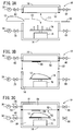
- FIGS. 3A through 3C operations of the affixing apparatus 10 will be described using FIGS. 3A through 3C , and FIGS. 4A through 4C .
- the affixing apparatus 10 is operated in the order shown in FIGS. 3A through 3C , and FIGS. 4A through 4C .
- FIG. 3A is a diagram for describing a process of attaching the decorative sheet 50 to a surface (lower surface) on a side of the affixing film 52 that faces toward the object to be decorated 12 or the support base 74.
- the decorative sheet 50 is attached to the lower surface of the affixing film 52.
- the object to be decorated 12 is set on the support base 74. Attachment of the decorative sheet 50, and setting of the object to be decorated 12 on the support base 74 may be carried out with either one of them being performed first, or they may be performed at the same time.
- a holding force adjusting process is performed by which the holding force of the decorative sheet 50 with respect to the affixing film 52 is made to differ locally.
- the holding force adjusting process will be described in detail later.
- FIG. 3B is a diagram for describing a process of placing the affixing film 52 in a facing position.
- the control unit 22 controls the raising and lowering mechanism 18, whereby as shown by the arrow (3), the cover member 16 is lowered to cover the vessel 14, and the affixing film 52 is placed in facing relation with respect to the object to be decorated 12.
- FIG. 3C is a diagram for describing a process of reducing pressure in the space 58 and the space 66.
- the control unit 22 opens the cover member side evacuation valve 62 and the vessel side evacuation valve 70, and activates the cover member pressure reducing pump 36 and the vessel pressure reducing pump 38, whereby as shown by the arrow (4), the fluid in the space 58 and the space 66 is evacuated, and the space 58 and the space 66 are reduced in pressure. At this time, since the pressures of both the space 58 and the space 66 are reduced together, no pressure difference is generated between the space 58 and the space 66.
- the control unit 22 controlling the support base raising and lowering mechanism 76 controlling the support base raising and lowering mechanism 76, as shown by the arrow (5), the object to be decorated 12 may be raised and brought into contact with the decorative sheet 50. Consequently, positional shifting of the position at which the decorative sheet 50 is affixed with respect to the object to be decorated 12 can be prevented.
- FIG. 4A is a diagram for describing a process of pressure bonding and affixing the decorative sheet 50 to the object to be decorated 12.
- the control unit 22 stops the pressure reducing action of the space 58 by closing the cover member side evacuation valve 62, and opens the cover member side introduction valve 60, whereby as shown by the arrow (6), fluid is introduced into the space 58. Since the fluid is evacuated and the space 66 is reduced in pressure, a pressure difference is generated between the space 58 and the space 66. Due to such a pressure difference, as shown by the arrow (7), the affixing film 52 is pressed downwardly and stretched, and the decorative sheet 50 is pressure bonded along the shape of the object to be decorated 12, and is affixed to the object to be decorated 12.
- the control unit 22 controlling the support base raising and lowering mechanism 76, as shown by the arrow (8), the object to be decorated 12 may be raised. Consequently, it is possible to suppress deterioration by suppressing the amount of stretching of the affixing film 52.
- FIG. 4B is a diagram for describing a process of separating the affixing film 52 from the object to be decorated 12.
- the control unit 22 stops the pressure reducing action of the space 66 by closing the vessel side evacuation valve 70, and opens the vessel side introduction valve 68, whereby as shown by the arrow (9), fluid is introduced into the space 66.
- the control unit 22 controls the support base raising and lowering mechanism 76, whereby as shown by the arrow (10), the object to be decorated 12 is lowered, and the affixing film 52 is separated from the decorated object 12.
- FIG. 4C is a diagram for describing a process of removing the decorated object 12 from the affixing apparatus 10.
- the control unit 22 controls the raising and lowering mechanism 18, whereby as shown by the arrow (11), the cover member 16 is raised.
- the decorated object 12, to which the decorative sheet 50 has been affixed is removed from the affixing apparatus 10.
- the operations of the pressure reducing mechanism 20, the cover member side introduction valve 60, the cover member side evacuation valve 62, the vessel side introduction valve 68, and the vessel side evacuation valve 70 are carried out by controls of the control unit 22, such operations may also be performed manually.
- the object to be decorated 12 includes a complex shape corresponding to the applied use thereof, and cases exist in which the affixing region of the object to be decorated 12, to which the decorative sheet 50 is affixed, does not have an entirely uniform surface shape.
- FIG. 5 is a view showing an example of the object to be decorated 12.
- an affixing region 80 (the region indicated by hatching) of the object to be decorated 12 includes a region 80a of a substantially planar shape, a region 80b of a curved shape having a large curvature, and a region 80c disposed between the region 80a and the region 80b.
- the region 80c has a shape that changes smoothly from the substantially planar shape of the region 80a to the curved shape of the region 80b. Consequently, the shape of the region 80c is such that the shape thereof is of a nearly planar shape as it nears the region 80a, and is of a curved shape the curvature of which becomes gradually greater as it approaches the side of the region 80b.
- FIG. 6 is a view of the affixing film 52 to which the decorative sheet 50 is attached, as seen from a lower side of the affixing film 52
- FIG. 7 is a cross-sectional view of the affixing film 52 to which the decorative sheet 50 is attached.
- the respective regions of the decorative sheet 50 that are affixed onto the regions 80a, 80b, 80c are indicated by regions 50a, 50b, 50c.
- the point O indicates the center of the affixing film 52.
- the region 50a of the decorative sheet 50 is affixed to the region 80a of the affixing region 80, and therefore, the region 50a preferably is affixed without being stretched relatively.
- the region 50a of the decorative sheet 50 were attached so that it were stretched greatly on the planar shaped region 80a, then the decorative sheet 50 would be affixed while exceeding the range of the affixing region 80. Further, as a result, there is a possibility that patterns or the like drawn on the decorative sheet 50 would become distorted.
- the region 50b of the decorative sheet 50 is affixed to the region 80b of the affixing region 80, and therefore, the region 50b preferably is affixed so that it is stretched greatly within the range of the affixing region 80.
- the region 50b of the decorative sheet 50 were attached so that it were not stretched significantly on the region 80b of a curved shape, then wrinkles could occur in the decorative sheet 50.
- the region 50c of the decorative sheet 50 is affixed to the region 80c of the affixing region 80, and therefore, the decorative sheet 50 preferably is affixed so that it is stretched depending on the shape of the region 80c, within the range of the affixing region 80.
- the region 50c of the decorative sheet 50 preferably is affixed while being stretched to a degree corresponding to the shape of the curved surface having a large curvature.
- the decorative sheet 50 can be affixed to the affixing region 80 of the object to be decorated 12, while the amount of stretching of the decorative sheet 50 is made to differ (made to change) locally, then the decorative sheet 50 can be affixed appropriately, and the accuracy or reliability with which the decorative sheet 50 is affixed is enhanced.
- the amount of stretching of the decorative sheet 50 is proportional to the holding force of the decorative sheet 50 with respect to the affixing film 52.
- the holding force is defined by the adhering force between the decorative sheet 50 and the affixing film 52, and the force by which the decorative sheet 50 and the affixing film 52 are attracted to each other.
- the affixing film 52 is placed in a stretched condition when the decorative sheet 50 is pressure bonded along the shape of the object to be decorated 12, in the case that the holding force between the decorative sheet 50 and the affixing film 52 is large (high), the decorative sheet 50 is stretched at an amount that is substantially the same as the amount of stretching of the affixing film 52. Conversely, in the case that the holding force between the decorative sheet 50 and the affixing film 52 is small, the decorative sheet 50 is only stretched by an amount that is smaller than the amount of stretching of the affixing film 52.
- the holding force of the decorative sheet 50 with respect to the affixing film 52 is controlled to differ locally, whereby the amount of stretching of the decorative sheet 50 can be made to differ locally.
- FIG. 8 is a view for explaining control of a holding force between the decorative sheet 50 and the affixing film 52 by a contact area between the decorative sheet 50 and the affixing film 52, in which portions of the decorative sheet 50 and the affixing film 52 are shown at an enlarged scale.
- the contact area between the affixing film 52 and the decorative sheet 50 becomes larger, the holding force by the intermolecular force increases, due to the fact that the distance between a contact surface 53 of the affixing film 52 and a contact surface 51 of the decorative sheet 50 is narrowed and the surfaces are placed in close contact.
- the contact area between the affixing film 52 and the decorative sheet 50 becomes smaller, the distance between the contact surface 53 and the contact surface 51 becomes greater, and therefore, the holding force by the intermolecular force decreases.
- the contact areas between the affixing film 52 and the respective regions 50a, 50b, 50c of the decorative sheet 50 are made greater depending on ideal amounts by which the respective regions 50a, 50b, 50c are to be stretched. Owing thereto, the holding force of the decorative sheet 50 with respect to the affixing film 52 can be made to differ locally, and the amount of stretching of the respective regions 50a, 50b, 50c of the decorative sheet 50 can be controlled, respectively.
- the contact area can be changed by the surface roughness of the contact surface 53 of the affixing film 52. More specifically, if the surface roughness of the surface (contact surface) 53 of the affixing film 52 on the side of the decorative sheet 50 is coarse, the contact area between the affixing film 52 and the decorative sheet 50 becomes small. On the other hand, if the surface roughness of the contact surface 53 of the affixing film 52 is fine (approximating a mirror surface), the contact area between the affixing film 52 and the decorative sheet 50 becomes large.
- the surface roughness can be changed by coating or pasting a powder 84, which serves as a type of contact area adjusting material, to the contact surface 51 of the decorative sheet 50.
- a powder 84 which serves as a type of contact area adjusting material
- the surface roughness is made coarse, the distance between the contact surfaces 51, 53 increases, and the contact area can be reduced.
- a large particle powder 84 (84b)
- the surface roughness is further coarsened, the distance between the contact surfaces 51, 53 further increases, and the contact area can be further reduced.
- the distance between the contact surfaces 51, 53 is narrowed, and the contact area can also be increased.
- the surface roughness of the surface (contact surface 51) of the decorative sheet 50 on the side of the affixing film 52 is constant, and is finely set.
- the surface roughness of the contact surface 51 of the decorative sheet 50 may also be changed, or the surface roughness of both the contact surface 53 of the affixing film 52 and the surface roughness of the contact surface 51 of the decorative sheet 50 may also be changed.
- FIG. 9 is a view for explaining control of a holding force between a decorative sheet 50 and the affixing film 52 by static electricity, in which portions of the decorative sheet 50 and the affixing film 52 are shown at an enlarged scale.
- the Coulomb force is weakened, and the holding force between the affixing film 52 and the decorative sheet 50 becomes small.
- the Coulomb force is strengthened, and the holding force between the affixing film 52 and the decorative sheet 50 becomes large.
- the charge amounts of the respective regions 50a, 50b, 50c of the decorative sheet 50, and the charge amounts of the respective regions of the affixing film 52 to which the regions 50a, 50b, 50c of the decorative sheet 50 are attached are made greater depending on ideal amounts by which the regions 50a, 50b, 50c are to be stretched. Owing thereto, the holding force of the decorative sheet 50 with respect to the affixing film 52 can be made to differ locally, and the amount of stretching of the respective regions 50a, 50b, 50c of the decorative sheet 50 can be controlled, respectively.
- the affixing film 52 is constituted from a material such a silicone or the like that is easy to be charged positively.
- the charge amount can be changed locally by locally reducing the positive charge amount of the affixing film 52 by ion neutralization using an ionizer device, and by locally increasing the charge amount using a charging device. Further, by bringing the decorative sheet 50 into contact with the positively charged affixing film 52, the decorative sheet 50 is charged with a negative charge in an amount corresponding to the positive charge amount by which the affixing film 52 has been charged. It should be noted that, although the affixing film 52 is charged with a positive charge, and the decorative sheet 50 is charged with a negative charge, the positive and negative charges thereof may be reversed.
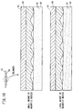
- FIG. 10 is a view for explaining control of a holding force between the decorative sheet 50 and the affixing film 52 by a magnetic force, in which portions of the decorative sheet 50 and the affixing film 52 are shown at an enlarged scale.
- a magnet 90 is stacked on the affixing film 52, and magnetic bodies 92 of iron particles or the like are kneaded into the decorative sheet 50. If the amount of the magnetic bodies 92 that are kneaded into the decorative sheet 50 is small, the magnetic force thereof is weakened, and the holding force between the affixing film 52 and the decorative sheet 50 becomes small. On the other hand, if the amount of the magnetic bodies 92 that are kneaded into the decorative sheet 50 is large, the magnetic force thereof is strengthened, and the holding force between the affixing film 52 and the decorative sheet 50 becomes large.
- the amount of the magnetic bodies 92 that are kneaded into the respective regions 50a, 50b, 50c of the decorative sheet 50 is made greater depending on ideal amounts by which the respective regions 50a, 50b, 50c are to be stretched. Owing thereto, the holding force of the decorative sheet 50 with respect to the affixing film 52 can be made to differ locally, and the amount of stretching of the respective regions 50a, 50b, 50c of the decorative sheet 50 can be controlled, respectively.
- a magnetic material may also be kneaded into the affixing film 52.
- a magnet may be provided on the decorative sheet 50, and the magnetic bodies 92 may be kneaded into the affixing film 52.
- a magnetism generating device that generates a magnetic force to attract the magnetic bodies 92 may be disposed on the side of the affixing film 52. In this case, the magnetic force generated by the magnetism generating device may be changed for each of respective regions of the affixing film 52.
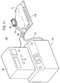
- FIG. 11 is a structural diagram of an affixing apparatus 100 according to a second embodiment. Constituent elements thereof which are the same as those in the aforementioned first embodiment are denoted by the same reference characters, and description of such features is omitted.
- the affixing apparatus 100 is equipped with an affixing mechanism 102 that affixes the decorative sheet 50 to the object to be decorated 12, and which is held manually and is capable of being moved, a pressure reducing pump 104 that reduces the pressure of a space between the affixing mechanism 102 and the object to be decorated 12, an introduction and evacuation valve 106, which is a three-way valve, for carrying out introduction and evacuation of fluid in the space between the affixing mechanism 102 and the object to be decorated 12, a control unit 108 that controls the pressure reducing pump 104 and the introduction and evacuation valve 106, and a support base 110 that supports the object to be decorated 12.
- a first port of the introduction and evacuation valve 106 is connected through a hose 112 to the pressure reducing pump 104, a second port is connected through a hose 114 to the affixing mechanism 102, and a third port is open to atmosphere.
- FIG. 12 is an enlarged cross-sectional view of an essential part of the affixing apparatus 100.
- the affixing mechanism 102 comprises a film holding frame 116 for retaining the affixing film 52 to which the decorative sheet 50 is attached as a decorative object on a lower surface thereof.
- the film holding frame 116 is a plate-shaped jig that supports an edge of the affixing film 52, and includes an opening 118 on an inner side thereof.
- the film holding frame 116 includes an upper holding frame 116a and a lower holding frame 116b, and retains the affixing film 52 by the upper holding frame 116a and the lower holding frame 116b sandwiching the affixing film 52 from above and below. It goes without saying that the opening 118 is disposed respectively in the upper holding frame 116a and the lower holding frame 116b.
- a handle 120 that can be grasped by hand is provided on the upper holding frame 116a.
- a frame-shaped packing 122 that seals the object to be decorated 12 and the lower holding frame 116b is disposed downwardly of the lower holding frame 116b.
- the introduction and evacuation valve 106 which performs introduction and evacuation of fluid in a space 124 between the object to be decorated 12 and the affixing film 52 that is formed in a state in which the packing 122 is pressed against the object to be decorated 12, and the lower holding frame 116b are connected through the hose 114.
- the introduction and evacuation valve 106 may be constituted by an evacuation valve that is used for evacuating the fluid, and an introduction valve that is used for introducing the fluid.
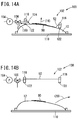
- FIGS. 13A through 13C operations of the affixing apparatus 100 according to the second embodiment will be described using FIGS. 13A through 13C , and FIGS. 14A through 14B .
- the affixing apparatus 100 is operated in the order shown in FIGS. 13A through 13C , and FIGS. 14A through 14B .
- FIG. 13A is a diagram for describing a process of attaching the decorative sheet 50 to a surface (lower surface) on a side of the affixing film 52 that faces toward the object to be decorated 12.
- the decorative sheet 50 is attached to the lower surface of the affixing film 52.
- the object to be decorated 12 is set on the support base 110. Attachment of the decorative sheet 50, and setting of the object to be decorated 12 on the support base 110 may be carried out with either one of them being performed first, or they may be performed at the same time.
- a holding force adjusting process is performed by which the holding force of the decorative sheet 50 with respect to the affixing film 52 is made to differ locally.
- FIG. 13B is a diagram for describing a process of placing the affixing film 52 in covering relation to the object to be decorated 12. As shown by the arrow (15), the affixing mechanism 102 is lowered and arranged so as to cover the object to be decorated 12, whereupon the packing 122 is placed in intimate contact with the object to be decorated 12.
- FIG. 13C is a diagram for describing a process of reducing pressure in the space 124 between the affixing film 52 and the object to be decorated 12, thereby pressure bonding and affixing the decorative sheet 50 to the object to be decorated 12.
- the control unit 108 opens communication between the first port and the second port of the introduction and evacuation valve 106, and activates the pressure reducing pump 104, whereby as shown by the arrow (16), fluid is evacuated from the space 124 between the affixing film 52 and the object to be decorated 12, and the space 124 is reduced in pressure.
- FIG. 14A is a diagram for describing a process of separating the affixing film 52 from the object to be decorated 12.
- Communication between the second port and the third port of the introduction and evacuation valve 106 is opened, whereupon as shown by the arrow (18), fluid such as external air or the like is introduced into the space 124 between the affixing film 52 and the object to be decorated 12.
- the affixing mechanism 102 is raised, and the affixing film 52 is separated from the decorated object 12.
- FIG. 14B is a diagram for describing a process of removing the decorated object 12 from the affixing apparatus 100.
- the decorated object 12 to which the decorative sheet 50 has been affixed is removed from the affixing apparatus 100.
- the holding force of the decorative sheet 50 with respect to the affixing film 52 is made to differ locally, the amount of stretching of the decorative sheet 50 in relation to the amount of stretching of the affixing film 52 can be controlled locally.
- the possibility for wrinkles to occur in the decorative sheet 50 can be controlled, while in addition, distortion of characters or patterns, etc., that are drawn on the decorative sheet 50 can be prevented.
Landscapes
- Chemical & Material Sciences (AREA)
- Dispersion Chemistry (AREA)
- Physics & Mathematics (AREA)
- Fluid Mechanics (AREA)
- Engineering & Computer Science (AREA)
- Mechanical Engineering (AREA)
- Decoration By Transfer Pictures (AREA)
- Lining Or Joining Of Plastics Or The Like (AREA)
- Diaphragms For Cameras (AREA)
- Lens Barrels (AREA)
- Labeling Devices (AREA)
- Laminated Bodies (AREA)
- Vehicle Waterproofing, Decoration, And Sanitation Devices (AREA)
Applications Claiming Priority (2)
| Application Number | Priority Date | Filing Date | Title |
|---|---|---|---|
| JP2013146585 | 2013-07-12 | ||
| PCT/JP2014/058935 WO2015004957A1 (ja) | 2013-07-12 | 2014-03-27 | 装飾体の貼り付け方法及び装飾体 |
Publications (3)
| Publication Number | Publication Date |
|---|---|
| EP3020568A1 true EP3020568A1 (de) | 2016-05-18 |
| EP3020568A4 EP3020568A4 (de) | 2017-06-07 |
| EP3020568B1 EP3020568B1 (de) | 2019-01-16 |
Family
ID=52279655
Family Applications (1)
| Application Number | Title | Priority Date | Filing Date |
|---|---|---|---|
| EP14822312.6A Not-in-force EP3020568B1 (de) | 2013-07-12 | 2014-03-27 | Verfahren zum befestigen eines schmuckgegenstands und schmuckgegenstand |
Country Status (7)
| Country | Link |
|---|---|
| US (1) | US10035373B2 (de) |
| EP (1) | EP3020568B1 (de) |
| JP (1) | JP6046255B2 (de) |
| CN (1) | CN105377574A (de) |
| BR (1) | BR112015032893A2 (de) |
| MY (1) | MY180734A (de) |
| WO (1) | WO2015004957A1 (de) |
Cited By (1)
| Publication number | Priority date | Publication date | Assignee | Title |
|---|---|---|---|---|
| WO2019166239A1 (de) * | 2018-02-27 | 2019-09-06 | Kautex Textron Gmbh & Co. Kg | Vorrichtung zum handhaben eines erwärmten kunststoffbauteils, system und verfahren |
Families Citing this family (3)
| Publication number | Priority date | Publication date | Assignee | Title |
|---|---|---|---|---|
| CN111038167B (zh) * | 2015-09-18 | 2022-03-29 | 本田技研工业株式会社 | 粘贴装置和粘贴方法 |
| GB2566752B (en) * | 2017-09-26 | 2020-09-16 | Univ Cranfield | Method of manufacturing a moulded article |
| DE102019200604A1 (de) | 2019-01-17 | 2020-07-23 | Karl Wörwag Lack- Und Farbenfabrik Gmbh & Co. Kg | Verfahren zur Produktion von Kraftfahrzeugen und hierfür geeignetes Werkzeug |
Family Cites Families (12)
| Publication number | Priority date | Publication date | Assignee | Title |
|---|---|---|---|---|
| US3886020A (en) * | 1972-08-17 | 1975-05-27 | Anchor Hocking Corp | Method of applying decals to surfaces of complex curvature |
| IT1188049B (it) * | 1985-10-17 | 1987-12-30 | G C R Applic Speciali Spa | Metodo e dispositivo per applicare una copertura protettiva provvisoria su pannelli per il rivestimento interno di veicoli o simili e pannelli provvisti di tale copertura protettiva provvisoria |
| JPS6295300A (ja) * | 1985-10-22 | 1987-05-01 | 日本写真印刷株式会社 | 立ち上がりのあるプラスチツク成形品への射出成形同時絵付転写材 |
| JP2764130B2 (ja) * | 1988-04-01 | 1998-06-11 | 大日本印刷株式会社 | 凹凸模様を転写する方法及びその方法に使用する転写シート |
| JPH02137991A (ja) * | 1988-11-18 | 1990-05-28 | Honda Motor Co Ltd | 外装部品外表面の絵付方法 |
| FR2693146B1 (fr) * | 1992-07-02 | 1994-08-19 | Snecma | Installation pour la fabrication par drapage de structures multicouches en matériaux composites. |
| JPH0648096A (ja) * | 1992-07-31 | 1994-02-22 | Nissha Printing Co Ltd | 転写製品の製造方法 |
| DE4423291A1 (de) * | 1994-07-02 | 1996-01-11 | Kurz Leonhard Fa | Prägefolie, insbesondere Heissprägefolie mit Dekorations- oder Sicherungselementen |
| JP2001113642A (ja) * | 1999-10-21 | 2001-04-24 | Toppan Printing Co Ltd | 化粧シート及び転写シート並びにそれらを使用した化粧方法 |
| WO2011071091A1 (ja) * | 2009-12-08 | 2011-06-16 | 本田技研工業株式会社 | 装飾体の貼付け方法及びその装置 |
| JP5249182B2 (ja) | 2009-12-08 | 2013-07-31 | 本田技研工業株式会社 | 装飾体の貼付け方法及びその装置 |
| JP2012091329A (ja) * | 2010-10-25 | 2012-05-17 | Toyota Motor Corp | 表皮材の貼り付け装置および貼り付け方法 |
-
2014
- 2014-03-27 MY MYPI2016700075A patent/MY180734A/en unknown
- 2014-03-27 EP EP14822312.6A patent/EP3020568B1/de not_active Not-in-force
- 2014-03-27 JP JP2015526186A patent/JP6046255B2/ja active Active
- 2014-03-27 BR BR112015032893A patent/BR112015032893A2/pt not_active Application Discontinuation
- 2014-03-27 WO PCT/JP2014/058935 patent/WO2015004957A1/ja not_active Ceased
- 2014-03-27 US US14/903,635 patent/US10035373B2/en active Active
- 2014-03-27 CN CN201480039629.5A patent/CN105377574A/zh active Pending
Cited By (1)
| Publication number | Priority date | Publication date | Assignee | Title |
|---|---|---|---|---|
| WO2019166239A1 (de) * | 2018-02-27 | 2019-09-06 | Kautex Textron Gmbh & Co. Kg | Vorrichtung zum handhaben eines erwärmten kunststoffbauteils, system und verfahren |
Also Published As
| Publication number | Publication date |
|---|---|
| EP3020568A4 (de) | 2017-06-07 |
| US20160144656A1 (en) | 2016-05-26 |
| WO2015004957A1 (ja) | 2015-01-15 |
| EP3020568B1 (de) | 2019-01-16 |
| BR112015032893A2 (pt) | 2017-07-25 |
| US10035373B2 (en) | 2018-07-31 |
| CN105377574A (zh) | 2016-03-02 |
| JP6046255B2 (ja) | 2016-12-14 |
| MY180734A (en) | 2020-12-08 |
| JPWO2015004957A1 (ja) | 2017-03-02 |
Similar Documents
| Publication | Publication Date | Title |
|---|---|---|
| EP3020568B1 (de) | Verfahren zum befestigen eines schmuckgegenstands und schmuckgegenstand | |
| JPH10233430A (ja) | 粘着テープ貼付け装置 | |
| JP2014220436A (ja) | 貼り合わせ分離方法及び分離装置 | |
| JP2016049620A (ja) | ワーク吸着方法及び装置 | |
| GB1449767A (en) | Method and de-ice for applying a sheet of plastics material to a solid body | |
| KR101669086B1 (ko) | 유리 기판의 지지 및 고정 장치 및 방법 | |
| JP4221271B2 (ja) | テープ貼付装置 | |
| JP2018167537A (ja) | 貼合装置 | |
| JP6564866B2 (ja) | 貼り付け装置及び貼り付け方法 | |
| CN102005395B (zh) | 真空贴装方法及装置 | |
| KR101389047B1 (ko) | 휴대단말기의 카메라커버 조립방법 및 그를 위한 조립장치 | |
| WO2006086160B1 (en) | Apparatus and method for moving envelopes | |
| JP6514580B2 (ja) | 保持装置および離間方法 | |
| CN108290344A (zh) | 局部加饰成型方法以及局部加饰成型装置 | |
| TW201703978A (zh) | 熱成形裝置及熱成形方法 | |
| JP5249182B2 (ja) | 装飾体の貼付け方法及びその装置 | |
| CN107579163A (zh) | 膜材封装冶具和oled的金属膜的封装方法 | |
| US20230014530A1 (en) | Affixing method and affixing apparatus | |
| JP7272640B2 (ja) | ワーク装着装置及びワーク貼合システム | |
| JP2696136B2 (ja) | 差圧成形における同時裏貼加工方法 | |
| JP2018141817A (ja) | 真空貼合装置及び表示装置用部材の製造方法 | |
| JP2010103137A (ja) | 粘着テープの貼付装置及び粘着テープの貼付方法 | |
| JP5832411B2 (ja) | 装飾体の貼り付け方法及び貼り付け装置 | |
| JP2019177615A (ja) | 積層装置 | |
| JPS6342840A (ja) | 真空ラミネ−ト方法および真空ラミネ−ト装置 |
Legal Events
| Date | Code | Title | Description |
|---|---|---|---|
| PUAI | Public reference made under article 153(3) epc to a published international application that has entered the european phase |
Free format text: ORIGINAL CODE: 0009012 |
|
| 17P | Request for examination filed |
Effective date: 20160112 |
|
| AK | Designated contracting states |
Kind code of ref document: A1 Designated state(s): AL AT BE BG CH CY CZ DE DK EE ES FI FR GB GR HR HU IE IS IT LI LT LU LV MC MK MT NL NO PL PT RO RS SE SI SK SM TR |
|
| AX | Request for extension of the european patent |
Extension state: BA ME |
|
| DAX | Request for extension of the european patent (deleted) | ||
| A4 | Supplementary search report drawn up and despatched |
Effective date: 20170509 |
|
| RIC1 | Information provided on ipc code assigned before grant |
Ipc: B44C 1/18 20060101ALI20170502BHEP Ipc: B44C 5/00 20060101AFI20170502BHEP Ipc: B44C 3/04 20060101ALI20170502BHEP Ipc: B44C 1/17 20060101ALI20170502BHEP |
|
| RIC1 | Information provided on ipc code assigned before grant |
Ipc: B44C 1/17 20060101ALI20180503BHEP Ipc: B44C 3/04 20060101ALI20180503BHEP Ipc: B44C 1/18 20060101ALI20180503BHEP Ipc: B44C 5/00 20060101AFI20180503BHEP Ipc: B44C 1/10 20060101ALI20180503BHEP Ipc: B30B 5/02 20060101ALI20180503BHEP |
|
| GRAP | Despatch of communication of intention to grant a patent |
Free format text: ORIGINAL CODE: EPIDOSNIGR1 |
|
| STAA | Information on the status of an ep patent application or granted ep patent |
Free format text: STATUS: GRANT OF PATENT IS INTENDED |
|
| GRAJ | Information related to disapproval of communication of intention to grant by the applicant or resumption of examination proceedings by the epo deleted |
Free format text: ORIGINAL CODE: EPIDOSDIGR1 |
|
| STAA | Information on the status of an ep patent application or granted ep patent |
Free format text: STATUS: REQUEST FOR EXAMINATION WAS MADE |
|
| INTG | Intention to grant announced |
Effective date: 20180717 |
|
| RAP1 | Party data changed (applicant data changed or rights of an application transferred) |
Owner name: HONDA MOTOR CO., LTD. |
|
| INTC | Intention to grant announced (deleted) | ||
| GRAP | Despatch of communication of intention to grant a patent |
Free format text: ORIGINAL CODE: EPIDOSNIGR1 |
|
| STAA | Information on the status of an ep patent application or granted ep patent |
Free format text: STATUS: GRANT OF PATENT IS INTENDED |
|
| INTG | Intention to grant announced |
Effective date: 20180907 |
|
| GRAS | Grant fee paid |
Free format text: ORIGINAL CODE: EPIDOSNIGR3 |
|
| GRAA | (expected) grant |
Free format text: ORIGINAL CODE: 0009210 |
|
| STAA | Information on the status of an ep patent application or granted ep patent |
Free format text: STATUS: THE PATENT HAS BEEN GRANTED |
|
| AK | Designated contracting states |
Kind code of ref document: B1 Designated state(s): AL AT BE BG CH CY CZ DE DK EE ES FI FR GB GR HR HU IE IS IT LI LT LU LV MC MK MT NL NO PL PT RO RS SE SI SK SM TR |
|
| REG | Reference to a national code |
Ref country code: GB Ref legal event code: FG4D |
|
| REG | Reference to a national code |
Ref country code: CH Ref legal event code: EP |
|
| REG | Reference to a national code |
Ref country code: IE Ref legal event code: FG4D |
|
| REG | Reference to a national code |
Ref country code: AT Ref legal event code: REF Ref document number: 1089434 Country of ref document: AT Kind code of ref document: T Effective date: 20190215 |
|
| REG | Reference to a national code |
Ref country code: DE Ref legal event code: R096 Ref document number: 602014040106 Country of ref document: DE |
|
| REG | Reference to a national code |
Ref country code: NL Ref legal event code: MP Effective date: 20190116 |
|
| REG | Reference to a national code |
Ref country code: LT Ref legal event code: MG4D |
|
| PG25 | Lapsed in a contracting state [announced via postgrant information from national office to epo] |
Ref country code: NL Free format text: LAPSE BECAUSE OF FAILURE TO SUBMIT A TRANSLATION OF THE DESCRIPTION OR TO PAY THE FEE WITHIN THE PRESCRIBED TIME-LIMIT Effective date: 20190116 |
|
| REG | Reference to a national code |
Ref country code: AT Ref legal event code: MK05 Ref document number: 1089434 Country of ref document: AT Kind code of ref document: T Effective date: 20190116 |
|
| PG25 | Lapsed in a contracting state [announced via postgrant information from national office to epo] |
Ref country code: ES Free format text: LAPSE BECAUSE OF FAILURE TO SUBMIT A TRANSLATION OF THE DESCRIPTION OR TO PAY THE FEE WITHIN THE PRESCRIBED TIME-LIMIT Effective date: 20190116 Ref country code: PT Free format text: LAPSE BECAUSE OF FAILURE TO SUBMIT A TRANSLATION OF THE DESCRIPTION OR TO PAY THE FEE WITHIN THE PRESCRIBED TIME-LIMIT Effective date: 20190516 Ref country code: SE Free format text: LAPSE BECAUSE OF FAILURE TO SUBMIT A TRANSLATION OF THE DESCRIPTION OR TO PAY THE FEE WITHIN THE PRESCRIBED TIME-LIMIT Effective date: 20190116 Ref country code: PL Free format text: LAPSE BECAUSE OF FAILURE TO SUBMIT A TRANSLATION OF THE DESCRIPTION OR TO PAY THE FEE WITHIN THE PRESCRIBED TIME-LIMIT Effective date: 20190116 Ref country code: LT Free format text: LAPSE BECAUSE OF FAILURE TO SUBMIT A TRANSLATION OF THE DESCRIPTION OR TO PAY THE FEE WITHIN THE PRESCRIBED TIME-LIMIT Effective date: 20190116 Ref country code: NO Free format text: LAPSE BECAUSE OF FAILURE TO SUBMIT A TRANSLATION OF THE DESCRIPTION OR TO PAY THE FEE WITHIN THE PRESCRIBED TIME-LIMIT Effective date: 20190416 Ref country code: FI Free format text: LAPSE BECAUSE OF FAILURE TO SUBMIT A TRANSLATION OF THE DESCRIPTION OR TO PAY THE FEE WITHIN THE PRESCRIBED TIME-LIMIT Effective date: 20190116 |
|
| PG25 | Lapsed in a contracting state [announced via postgrant information from national office to epo] |
Ref country code: BG Free format text: LAPSE BECAUSE OF FAILURE TO SUBMIT A TRANSLATION OF THE DESCRIPTION OR TO PAY THE FEE WITHIN THE PRESCRIBED TIME-LIMIT Effective date: 20190416 Ref country code: GR Free format text: LAPSE BECAUSE OF FAILURE TO SUBMIT A TRANSLATION OF THE DESCRIPTION OR TO PAY THE FEE WITHIN THE PRESCRIBED TIME-LIMIT Effective date: 20190417 Ref country code: IS Free format text: LAPSE BECAUSE OF FAILURE TO SUBMIT A TRANSLATION OF THE DESCRIPTION OR TO PAY THE FEE WITHIN THE PRESCRIBED TIME-LIMIT Effective date: 20190516 Ref country code: RS Free format text: LAPSE BECAUSE OF FAILURE TO SUBMIT A TRANSLATION OF THE DESCRIPTION OR TO PAY THE FEE WITHIN THE PRESCRIBED TIME-LIMIT Effective date: 20190116 Ref country code: LV Free format text: LAPSE BECAUSE OF FAILURE TO SUBMIT A TRANSLATION OF THE DESCRIPTION OR TO PAY THE FEE WITHIN THE PRESCRIBED TIME-LIMIT Effective date: 20190116 Ref country code: HR Free format text: LAPSE BECAUSE OF FAILURE TO SUBMIT A TRANSLATION OF THE DESCRIPTION OR TO PAY THE FEE WITHIN THE PRESCRIBED TIME-LIMIT Effective date: 20190116 |
|
| REG | Reference to a national code |
Ref country code: DE Ref legal event code: R097 Ref document number: 602014040106 Country of ref document: DE |
|
| PG25 | Lapsed in a contracting state [announced via postgrant information from national office to epo] |
Ref country code: CZ Free format text: LAPSE BECAUSE OF FAILURE TO SUBMIT A TRANSLATION OF THE DESCRIPTION OR TO PAY THE FEE WITHIN THE PRESCRIBED TIME-LIMIT Effective date: 20190116 Ref country code: RO Free format text: LAPSE BECAUSE OF FAILURE TO SUBMIT A TRANSLATION OF THE DESCRIPTION OR TO PAY THE FEE WITHIN THE PRESCRIBED TIME-LIMIT Effective date: 20190116 Ref country code: IT Free format text: LAPSE BECAUSE OF FAILURE TO SUBMIT A TRANSLATION OF THE DESCRIPTION OR TO PAY THE FEE WITHIN THE PRESCRIBED TIME-LIMIT Effective date: 20190116 Ref country code: AL Free format text: LAPSE BECAUSE OF FAILURE TO SUBMIT A TRANSLATION OF THE DESCRIPTION OR TO PAY THE FEE WITHIN THE PRESCRIBED TIME-LIMIT Effective date: 20190116 Ref country code: MC Free format text: LAPSE BECAUSE OF FAILURE TO SUBMIT A TRANSLATION OF THE DESCRIPTION OR TO PAY THE FEE WITHIN THE PRESCRIBED TIME-LIMIT Effective date: 20190116 Ref country code: SK Free format text: LAPSE BECAUSE OF FAILURE TO SUBMIT A TRANSLATION OF THE DESCRIPTION OR TO PAY THE FEE WITHIN THE PRESCRIBED TIME-LIMIT Effective date: 20190116 Ref country code: DK Free format text: LAPSE BECAUSE OF FAILURE TO SUBMIT A TRANSLATION OF THE DESCRIPTION OR TO PAY THE FEE WITHIN THE PRESCRIBED TIME-LIMIT Effective date: 20190116 Ref country code: AT Free format text: LAPSE BECAUSE OF FAILURE TO SUBMIT A TRANSLATION OF THE DESCRIPTION OR TO PAY THE FEE WITHIN THE PRESCRIBED TIME-LIMIT Effective date: 20190116 Ref country code: EE Free format text: LAPSE BECAUSE OF FAILURE TO SUBMIT A TRANSLATION OF THE DESCRIPTION OR TO PAY THE FEE WITHIN THE PRESCRIBED TIME-LIMIT Effective date: 20190116 |
|
| REG | Reference to a national code |
Ref country code: CH Ref legal event code: PL |
|
| PLBE | No opposition filed within time limit |
Free format text: ORIGINAL CODE: 0009261 |
|
| STAA | Information on the status of an ep patent application or granted ep patent |
Free format text: STATUS: NO OPPOSITION FILED WITHIN TIME LIMIT |
|
| PG25 | Lapsed in a contracting state [announced via postgrant information from national office to epo] |
Ref country code: SM Free format text: LAPSE BECAUSE OF FAILURE TO SUBMIT A TRANSLATION OF THE DESCRIPTION OR TO PAY THE FEE WITHIN THE PRESCRIBED TIME-LIMIT Effective date: 20190116 Ref country code: LU Free format text: LAPSE BECAUSE OF NON-PAYMENT OF DUE FEES Effective date: 20190327 |
|
| REG | Reference to a national code |
Ref country code: BE Ref legal event code: MM Effective date: 20190331 |
|
| 26N | No opposition filed |
Effective date: 20191017 |
|
| PG25 | Lapsed in a contracting state [announced via postgrant information from national office to epo] |
Ref country code: LI Free format text: LAPSE BECAUSE OF NON-PAYMENT OF DUE FEES Effective date: 20190331 Ref country code: CH Free format text: LAPSE BECAUSE OF NON-PAYMENT OF DUE FEES Effective date: 20190331 Ref country code: IE Free format text: LAPSE BECAUSE OF NON-PAYMENT OF DUE FEES Effective date: 20190327 |
|
| PG25 | Lapsed in a contracting state [announced via postgrant information from national office to epo] |
Ref country code: SI Free format text: LAPSE BECAUSE OF FAILURE TO SUBMIT A TRANSLATION OF THE DESCRIPTION OR TO PAY THE FEE WITHIN THE PRESCRIBED TIME-LIMIT Effective date: 20190116 Ref country code: BE Free format text: LAPSE BECAUSE OF NON-PAYMENT OF DUE FEES Effective date: 20190331 Ref country code: FR Free format text: LAPSE BECAUSE OF NON-PAYMENT OF DUE FEES Effective date: 20190331 |
|
| PG25 | Lapsed in a contracting state [announced via postgrant information from national office to epo] |
Ref country code: TR Free format text: LAPSE BECAUSE OF FAILURE TO SUBMIT A TRANSLATION OF THE DESCRIPTION OR TO PAY THE FEE WITHIN THE PRESCRIBED TIME-LIMIT Effective date: 20190116 |
|
| PG25 | Lapsed in a contracting state [announced via postgrant information from national office to epo] |
Ref country code: MT Free format text: LAPSE BECAUSE OF NON-PAYMENT OF DUE FEES Effective date: 20190327 |
|
| PG25 | Lapsed in a contracting state [announced via postgrant information from national office to epo] |
Ref country code: CY Free format text: LAPSE BECAUSE OF FAILURE TO SUBMIT A TRANSLATION OF THE DESCRIPTION OR TO PAY THE FEE WITHIN THE PRESCRIBED TIME-LIMIT Effective date: 20190116 |
|
| PG25 | Lapsed in a contracting state [announced via postgrant information from national office to epo] |
Ref country code: HU Free format text: LAPSE BECAUSE OF FAILURE TO SUBMIT A TRANSLATION OF THE DESCRIPTION OR TO PAY THE FEE WITHIN THE PRESCRIBED TIME-LIMIT; INVALID AB INITIO Effective date: 20140327 |
|
| PGFP | Annual fee paid to national office [announced via postgrant information from national office to epo] |
Ref country code: GB Payment date: 20220203 Year of fee payment: 9 Ref country code: DE Payment date: 20220203 Year of fee payment: 9 |
|
| PG25 | Lapsed in a contracting state [announced via postgrant information from national office to epo] |
Ref country code: MK Free format text: LAPSE BECAUSE OF FAILURE TO SUBMIT A TRANSLATION OF THE DESCRIPTION OR TO PAY THE FEE WITHIN THE PRESCRIBED TIME-LIMIT Effective date: 20190116 |
|
| REG | Reference to a national code |
Ref country code: DE Ref legal event code: R119 Ref document number: 602014040106 Country of ref document: DE |
|
| GBPC | Gb: european patent ceased through non-payment of renewal fee |
Effective date: 20230327 |
|
| PG25 | Lapsed in a contracting state [announced via postgrant information from national office to epo] |
Ref country code: GB Free format text: LAPSE BECAUSE OF NON-PAYMENT OF DUE FEES Effective date: 20230327 |
|
| PG25 | Lapsed in a contracting state [announced via postgrant information from national office to epo] |
Ref country code: GB Free format text: LAPSE BECAUSE OF NON-PAYMENT OF DUE FEES Effective date: 20230327 Ref country code: DE Free format text: LAPSE BECAUSE OF NON-PAYMENT OF DUE FEES Effective date: 20231003 |