EP3021002B1 - Élément de glissement stratifié et palier lisse faisant appel audit élément de glissement stratifié - Google Patents
Élément de glissement stratifié et palier lisse faisant appel audit élément de glissement stratifié Download PDFInfo
- Publication number
- EP3021002B1 EP3021002B1 EP14822878.6A EP14822878A EP3021002B1 EP 3021002 B1 EP3021002 B1 EP 3021002B1 EP 14822878 A EP14822878 A EP 14822878A EP 3021002 B1 EP3021002 B1 EP 3021002B1
- Authority
- EP
- European Patent Office
- Prior art keywords
- laminate
- flat surface
- sliding member
- base body
- laminated
- Prior art date
- Legal status (The legal status is an assumption and is not a legal conclusion. Google has not performed a legal analysis and makes no representation as to the accuracy of the status listed.)
- Active
Links
Images



Classifications
-
- E—FIXED CONSTRUCTIONS
- E04—BUILDING
- E04H—BUILDINGS OR LIKE STRUCTURES FOR PARTICULAR PURPOSES; SWIMMING OR SPLASH BATHS OR POOLS; MASTS; FENCING; TENTS OR CANOPIES, IN GENERAL
- E04H9/00—Buildings, groups of buildings or shelters adapted to withstand or provide protection against abnormal external influences, e.g. war-like action, earthquake or extreme climate
- E04H9/02—Buildings, groups of buildings or shelters adapted to withstand or provide protection against abnormal external influences, e.g. war-like action, earthquake or extreme climate withstanding earthquake or sinking of ground
- E04H9/021—Bearing, supporting or connecting constructions specially adapted for such buildings
-
- A—HUMAN NECESSITIES
- A47—FURNITURE; DOMESTIC ARTICLES OR APPLIANCES; COFFEE MILLS; SPICE MILLS; SUCTION CLEANERS IN GENERAL
- A47B—TABLES; DESKS; OFFICE FURNITURE; CABINETS; DRAWERS; GENERAL DETAILS OF FURNITURE
- A47B91/00—Feet for furniture in general
- A47B91/06—Gliders or the like
-
- C—CHEMISTRY; METALLURGY
- C10—PETROLEUM, GAS OR COKE INDUSTRIES; TECHNICAL GASES CONTAINING CARBON MONOXIDE; FUELS; LUBRICANTS; PEAT
- C10M—LUBRICATING COMPOSITIONS; USE OF CHEMICAL SUBSTANCES EITHER ALONE OR AS LUBRICATING INGREDIENTS IN A LUBRICATING COMPOSITION
- C10M101/00—Lubricating compositions characterised by the base-material being a mineral or fatty oil
- C10M101/02—Petroleum fractions
- C10M101/025—Petroleum fractions waxes
-
- C—CHEMISTRY; METALLURGY
- C10—PETROLEUM, GAS OR COKE INDUSTRIES; TECHNICAL GASES CONTAINING CARBON MONOXIDE; FUELS; LUBRICANTS; PEAT
- C10M—LUBRICATING COMPOSITIONS; USE OF CHEMICAL SUBSTANCES EITHER ALONE OR AS LUBRICATING INGREDIENTS IN A LUBRICATING COMPOSITION
- C10M107/00—Lubricating compositions characterised by the base-material being a macromolecular compound
- C10M107/02—Hydrocarbon polymers; Hydrocarbon polymers modified by oxidation
- C10M107/04—Polyethylene
-
- C—CHEMISTRY; METALLURGY
- C10—PETROLEUM, GAS OR COKE INDUSTRIES; TECHNICAL GASES CONTAINING CARBON MONOXIDE; FUELS; LUBRICANTS; PEAT
- C10M—LUBRICATING COMPOSITIONS; USE OF CHEMICAL SUBSTANCES EITHER ALONE OR AS LUBRICATING INGREDIENTS IN A LUBRICATING COMPOSITION
- C10M107/00—Lubricating compositions characterised by the base-material being a macromolecular compound
- C10M107/38—Lubricating compositions characterised by the base-material being a macromolecular compound containing halogen
-
- C—CHEMISTRY; METALLURGY
- C10—PETROLEUM, GAS OR COKE INDUSTRIES; TECHNICAL GASES CONTAINING CARBON MONOXIDE; FUELS; LUBRICANTS; PEAT
- C10M—LUBRICATING COMPOSITIONS; USE OF CHEMICAL SUBSTANCES EITHER ALONE OR AS LUBRICATING INGREDIENTS IN A LUBRICATING COMPOSITION
- C10M111/00—Lubrication compositions characterised by the base-material being a mixture of two or more compounds covered by more than one of the main groups C10M101/00 - C10M109/00, each of these compounds being essential
- C10M111/04—Lubrication compositions characterised by the base-material being a mixture of two or more compounds covered by more than one of the main groups C10M101/00 - C10M109/00, each of these compounds being essential at least one of them being a macromolecular organic compound
-
- C—CHEMISTRY; METALLURGY
- C10—PETROLEUM, GAS OR COKE INDUSTRIES; TECHNICAL GASES CONTAINING CARBON MONOXIDE; FUELS; LUBRICANTS; PEAT
- C10M—LUBRICATING COMPOSITIONS; USE OF CHEMICAL SUBSTANCES EITHER ALONE OR AS LUBRICATING INGREDIENTS IN A LUBRICATING COMPOSITION
- C10M125/00—Lubricating compositions characterised by the additive being an inorganic material
- C10M125/24—Compounds containing phosphorus, arsenic or antimony
-
- C—CHEMISTRY; METALLURGY
- C10—PETROLEUM, GAS OR COKE INDUSTRIES; TECHNICAL GASES CONTAINING CARBON MONOXIDE; FUELS; LUBRICANTS; PEAT
- C10M—LUBRICATING COMPOSITIONS; USE OF CHEMICAL SUBSTANCES EITHER ALONE OR AS LUBRICATING INGREDIENTS IN A LUBRICATING COMPOSITION
- C10M133/00—Lubricating compositions characterised by the additive being an organic non-macromolecular compound containing nitrogen
- C10M133/02—Lubricating compositions characterised by the additive being an organic non-macromolecular compound containing nitrogen having a carbon chain of less than 30 atoms
- C10M133/38—Heterocyclic nitrogen compounds
- C10M133/40—Six-membered ring containing nitrogen and carbon only
- C10M133/42—Triazines
-
- C—CHEMISTRY; METALLURGY
- C10—PETROLEUM, GAS OR COKE INDUSTRIES; TECHNICAL GASES CONTAINING CARBON MONOXIDE; FUELS; LUBRICANTS; PEAT
- C10M—LUBRICATING COMPOSITIONS; USE OF CHEMICAL SUBSTANCES EITHER ALONE OR AS LUBRICATING INGREDIENTS IN A LUBRICATING COMPOSITION
- C10M169/00—Lubricating compositions characterised by containing as components a mixture of at least two types of ingredient selected from base-materials, thickeners or additives, covered by the preceding groups, each of these compounds being essential
- C10M169/04—Mixtures of base-materials and additives
-
- E—FIXED CONSTRUCTIONS
- E01—CONSTRUCTION OF ROADS, RAILWAYS, OR BRIDGES
- E01D—CONSTRUCTION OF BRIDGES, ELEVATED ROADWAYS OR VIADUCTS; ASSEMBLY OF BRIDGES
- E01D19/00—Structural or constructional details of bridges
- E01D19/04—Bearings; Hinges
- E01D19/042—Mechanical bearings
-
- E—FIXED CONSTRUCTIONS
- E01—CONSTRUCTION OF ROADS, RAILWAYS, OR BRIDGES
- E01D—CONSTRUCTION OF BRIDGES, ELEVATED ROADWAYS OR VIADUCTS; ASSEMBLY OF BRIDGES
- E01D19/00—Structural or constructional details of bridges
- E01D19/04—Bearings; Hinges
- E01D19/042—Mechanical bearings
- E01D19/046—Spherical bearings
-
- E—FIXED CONSTRUCTIONS
- E01—CONSTRUCTION OF ROADS, RAILWAYS, OR BRIDGES
- E01D—CONSTRUCTION OF BRIDGES, ELEVATED ROADWAYS OR VIADUCTS; ASSEMBLY OF BRIDGES
- E01D19/00—Structural or constructional details of bridges
- E01D19/04—Bearings; Hinges
- E01D19/042—Mechanical bearings
- E01D19/047—Pot bearings
-
- E—FIXED CONSTRUCTIONS
- E04—BUILDING
- E04B—GENERAL BUILDING CONSTRUCTIONS; WALLS, e.g. PARTITIONS; ROOFS; FLOORS; CEILINGS; INSULATION OR OTHER PROTECTION OF BUILDINGS
- E04B1/00—Constructions in general; Structures which are not restricted either to walls, e.g. partitions, or floors or ceilings or roofs
- E04B1/62—Insulation or other protection; Elements or use of specified material therefor
- E04B1/92—Protection against other undesired influences or dangers
- E04B1/98—Protection against other undesired influences or dangers against vibrations or shocks; against mechanical destruction, e.g. by air-raids
-
- F—MECHANICAL ENGINEERING; LIGHTING; HEATING; WEAPONS; BLASTING
- F16—ENGINEERING ELEMENTS AND UNITS; GENERAL MEASURES FOR PRODUCING AND MAINTAINING EFFECTIVE FUNCTIONING OF MACHINES OR INSTALLATIONS; THERMAL INSULATION IN GENERAL
- F16C—SHAFTS; FLEXIBLE SHAFTS; ELEMENTS OR CRANKSHAFT MECHANISMS; ROTARY BODIES OTHER THAN GEARING ELEMENTS; BEARINGS
- F16C17/00—Sliding-contact bearings for exclusively rotary movement
- F16C17/04—Sliding-contact bearings for exclusively rotary movement for axial load only
-
- F—MECHANICAL ENGINEERING; LIGHTING; HEATING; WEAPONS; BLASTING
- F16—ENGINEERING ELEMENTS AND UNITS; GENERAL MEASURES FOR PRODUCING AND MAINTAINING EFFECTIVE FUNCTIONING OF MACHINES OR INSTALLATIONS; THERMAL INSULATION IN GENERAL
- F16C—SHAFTS; FLEXIBLE SHAFTS; ELEMENTS OR CRANKSHAFT MECHANISMS; ROTARY BODIES OTHER THAN GEARING ELEMENTS; BEARINGS
- F16C33/00—Parts of bearings; Special methods for making bearings or parts thereof
- F16C33/02—Parts of sliding-contact bearings
- F16C33/04—Brasses; Bushes; Linings
- F16C33/06—Sliding surface mainly made of metal
- F16C33/12—Structural composition; Use of special materials or surface treatments, e.g. for rust-proofing
- F16C33/122—Multilayer structures of sleeves, washers or liners
-
- C—CHEMISTRY; METALLURGY
- C10—PETROLEUM, GAS OR COKE INDUSTRIES; TECHNICAL GASES CONTAINING CARBON MONOXIDE; FUELS; LUBRICANTS; PEAT
- C10M—LUBRICATING COMPOSITIONS; USE OF CHEMICAL SUBSTANCES EITHER ALONE OR AS LUBRICATING INGREDIENTS IN A LUBRICATING COMPOSITION
- C10M2201/00—Inorganic compounds or elements as ingredients in lubricant compositions
- C10M2201/085—Phosphorus oxides, acids or salts
-
- C—CHEMISTRY; METALLURGY
- C10—PETROLEUM, GAS OR COKE INDUSTRIES; TECHNICAL GASES CONTAINING CARBON MONOXIDE; FUELS; LUBRICANTS; PEAT
- C10M—LUBRICATING COMPOSITIONS; USE OF CHEMICAL SUBSTANCES EITHER ALONE OR AS LUBRICATING INGREDIENTS IN A LUBRICATING COMPOSITION
- C10M2201/00—Inorganic compounds or elements as ingredients in lubricant compositions
- C10M2201/085—Phosphorus oxides, acids or salts
- C10M2201/0853—Phosphorus oxides, acids or salts used as base material
-
- C—CHEMISTRY; METALLURGY
- C10—PETROLEUM, GAS OR COKE INDUSTRIES; TECHNICAL GASES CONTAINING CARBON MONOXIDE; FUELS; LUBRICANTS; PEAT
- C10M—LUBRICATING COMPOSITIONS; USE OF CHEMICAL SUBSTANCES EITHER ALONE OR AS LUBRICATING INGREDIENTS IN A LUBRICATING COMPOSITION
- C10M2205/00—Organic macromolecular hydrocarbon compounds or fractions, whether or not modified by oxidation as ingredients in lubricant compositions
- C10M2205/14—Synthetic waxes, e.g. polythene waxes
- C10M2205/143—Synthetic waxes, e.g. polythene waxes used as base material
-
- C—CHEMISTRY; METALLURGY
- C10—PETROLEUM, GAS OR COKE INDUSTRIES; TECHNICAL GASES CONTAINING CARBON MONOXIDE; FUELS; LUBRICANTS; PEAT
- C10M—LUBRICATING COMPOSITIONS; USE OF CHEMICAL SUBSTANCES EITHER ALONE OR AS LUBRICATING INGREDIENTS IN A LUBRICATING COMPOSITION
- C10M2205/00—Organic macromolecular hydrocarbon compounds or fractions, whether or not modified by oxidation as ingredients in lubricant compositions
- C10M2205/16—Paraffin waxes; Petrolatum, e.g. slack wax
- C10M2205/163—Paraffin waxes; Petrolatum, e.g. slack wax used as base material
-
- C—CHEMISTRY; METALLURGY
- C10—PETROLEUM, GAS OR COKE INDUSTRIES; TECHNICAL GASES CONTAINING CARBON MONOXIDE; FUELS; LUBRICANTS; PEAT
- C10M—LUBRICATING COMPOSITIONS; USE OF CHEMICAL SUBSTANCES EITHER ALONE OR AS LUBRICATING INGREDIENTS IN A LUBRICATING COMPOSITION
- C10M2213/00—Organic macromolecular compounds containing halogen as ingredients in lubricant compositions
- C10M2213/06—Perfluoro polymers
- C10M2213/062—Polytetrafluoroethylene [PTFE]
- C10M2213/0623—Polytetrafluoroethylene [PTFE] used as base material
-
- C—CHEMISTRY; METALLURGY
- C10—PETROLEUM, GAS OR COKE INDUSTRIES; TECHNICAL GASES CONTAINING CARBON MONOXIDE; FUELS; LUBRICANTS; PEAT
- C10M—LUBRICATING COMPOSITIONS; USE OF CHEMICAL SUBSTANCES EITHER ALONE OR AS LUBRICATING INGREDIENTS IN A LUBRICATING COMPOSITION
- C10M2215/00—Organic non-macromolecular compounds containing nitrogen as ingredients in lubricant Compositions
- C10M2215/22—Heterocyclic nitrogen compounds
- C10M2215/2203—Heterocyclic nitrogen compounds used as base material
-
- C—CHEMISTRY; METALLURGY
- C10—PETROLEUM, GAS OR COKE INDUSTRIES; TECHNICAL GASES CONTAINING CARBON MONOXIDE; FUELS; LUBRICANTS; PEAT
- C10M—LUBRICATING COMPOSITIONS; USE OF CHEMICAL SUBSTANCES EITHER ALONE OR AS LUBRICATING INGREDIENTS IN A LUBRICATING COMPOSITION
- C10M2215/00—Organic non-macromolecular compounds containing nitrogen as ingredients in lubricant Compositions
- C10M2215/22—Heterocyclic nitrogen compounds
- C10M2215/221—Six-membered rings containing nitrogen and carbon only
- C10M2215/222—Triazines
-
- C—CHEMISTRY; METALLURGY
- C10—PETROLEUM, GAS OR COKE INDUSTRIES; TECHNICAL GASES CONTAINING CARBON MONOXIDE; FUELS; LUBRICANTS; PEAT
- C10M—LUBRICATING COMPOSITIONS; USE OF CHEMICAL SUBSTANCES EITHER ALONE OR AS LUBRICATING INGREDIENTS IN A LUBRICATING COMPOSITION
- C10M2223/00—Organic non-macromolecular compounds containing phosphorus as ingredients in lubricant compositions
- C10M2223/02—Organic non-macromolecular compounds containing phosphorus as ingredients in lubricant compositions having no phosphorus-to-carbon bonds
- C10M2223/04—Phosphate esters
-
- C—CHEMISTRY; METALLURGY
- C10—PETROLEUM, GAS OR COKE INDUSTRIES; TECHNICAL GASES CONTAINING CARBON MONOXIDE; FUELS; LUBRICANTS; PEAT
- C10N—INDEXING SCHEME ASSOCIATED WITH SUBCLASS C10M RELATING TO LUBRICATING COMPOSITIONS
- C10N2030/00—Specified physical or chemical properties which is improved by the additive characterising the lubricating composition, e.g. multifunctional additives
- C10N2030/06—Oiliness; Film-strength; Anti-wear; Resistance to extreme pressure
-
- C—CHEMISTRY; METALLURGY
- C10—PETROLEUM, GAS OR COKE INDUSTRIES; TECHNICAL GASES CONTAINING CARBON MONOXIDE; FUELS; LUBRICANTS; PEAT
- C10N—INDEXING SCHEME ASSOCIATED WITH SUBCLASS C10M RELATING TO LUBRICATING COMPOSITIONS
- C10N2050/00—Form in which the lubricant is applied to the material being lubricated
- C10N2050/015—Dispersions of solid lubricants
- C10N2050/02—Dispersions of solid lubricants dissolved or suspended in a carrier which subsequently evaporates to leave a lubricant coating
-
- C—CHEMISTRY; METALLURGY
- C10—PETROLEUM, GAS OR COKE INDUSTRIES; TECHNICAL GASES CONTAINING CARBON MONOXIDE; FUELS; LUBRICANTS; PEAT
- C10N—INDEXING SCHEME ASSOCIATED WITH SUBCLASS C10M RELATING TO LUBRICATING COMPOSITIONS
- C10N2050/00—Form in which the lubricant is applied to the material being lubricated
- C10N2050/08—Solids
Definitions
- the present invention relates to a laminated sliding member and a sliding bearing using the laminated sliding member.
- a method is adopted, among others, wherein a cotton fabric base material is immersed in a phenolic resin varnish with a solid lubricant of such as a powder of graphite, molybdenum disulfide, or polytetrafluoroethylene resin dispersedly contained therein, and is then pulled up and appropriately heated to allow a solvent to dissipate, thereby obtaining a prepreg in which the solid lubricant is adhered to and impregnated into the cotton fabric base material, and this prepreg is laminated and molded.
- a solid lubricant such as a powder of graphite, molybdenum disulfide, or polytetrafluoroethylene resin dispersedly contained therein
- JP 2004 190804 discloses a sliding member composed of a substrate of a square column consisting of woven fabric reinforced thermosetting synthetic resin, a surface layer material that is joined and integrated with another face of the substrate, several pieces of recessed parts that are formed on the surface layer material, and a covering layer consisting of the lubricating composition that is filled up in the recessed parts of the surface layer material and covered through the fluffiness formed on a surface of the surface layer material.
- JP 2009 091447 discloses in the fiber-reinforced resin composition for the sliding member, a polyester fiber textile fabric is impregnated with a resin composition which comprises a resol type phenol resin synthesized from phenols containing 50-100 mol% of bisphenol A and formaldehyde, using amines as a catalyst, having a number average molecular weight Mn of 500-1,000, as measured by the gel permeation chromatography, and having a dispersion degree Mw/Mn as a ratio of a weight average molecular weight Mw and a number average molecular weight Mn of 2.5-15, and a tetrafluoroethylene resin.
- the resin composition preferably comprises 40-60 wt.% of the resol type phenol resin, 10-30 wt.% of the tetrafluoroethylene resin and 25-35 wt.% of the polyester fiber textile fabric.
- the mixing ratio of the solid lubricant can be increased, the mixture of the phenolic resin and the solid lubricant is not sufficiently filled into gaps between fibrous tissues of the cotton fabric base material by simple immersion, and the mixture cannot necessarily be adhered sufficiently to the base material. If lamination molding is effected by using such a prepreg, the laminated sliding member obtained can possibly undergo interlayer delamination, with the result that the mechanical strength of the laminated sliding member can possibly decline appreciably.
- Patent Document 1 discloses a method wherein the solid lubricant is adhered to substantially only the surface of a reinforcing base material by impregnating the reinforcing base material with a synthetic resin varnish in advance and then by applying a varnish containing a solid lubricant to this varnish-impregnated reinforcing base material or applying an aqueous dispersion of the solid lubricant thereto.
- the low friction properties, wear resistance, and the like of the laminated sliding member are not necessarily sufficient.
- a seismic isolation apparatus is disclosed in Patent Document 2, wherein a polyethylene terephthalate woven fabric is impregnated with a resin composition in which a tetrafluoroethylene resin is added to an unsaturated polyester resin.
- Such a sliding member enables application to a sliding seismic isolation apparatus which could not be achieved by conventional sliding members.
- the initiation of sliding due to the seismic force is largely affected by the level of the coefficient of friction, and in the case where the coefficient of friction is 0.1 or thereabouts, the sliding member does not start sliding unless the seismic force reaches 0.1G (gal), so that the sliding member proposed in Patent Document 2 is still not necessarily satisfactory in terms of the low friction properties and has the possibility of hampering the function of the seismic isolation apparatus.
- the present invention has been devised in view of the above-described circumstances, and its object is to provide a laminated sliding member which has low friction properties, and which, when subjected to high-velocity sliding during an earthquake, is capable of preventing the efflux of a solid lubricant layer due to a rise in sliding frictional heat, and which, even if a load is concentrated on the sliding surface, does not cause such as damage and deformation of the solid lubricant layer in the sliding surface, as well as a sliding bearing using the laminated sliding member.
- a laminated sliding member in accordance with the present invention comprises: a base body having a plurality of recessed portions in one flat surface thereof; and a solid lubricant layer adhered to at least the one flat surface of the base body in such a manner as to extend to the recessed portions of the base body, wherein the base body has a laminate having the one flat surface and formed by superposing and mutually joining a plurality of polyester fiber woven fabrics impregnated with a resol-type phenolic resin containing a polytetrafluoroethylene resin, the plurality of recessed portions being disposed in the laminate by being located in an area exclusive of and inwardly of an annular outer flat surface of the one flat surface of the laminate, bounded by an outer peripheral edge of the one flat surface of the laminate and by an imaginary line located in such a way as to be spaced apart a predetermined distance inwardly from the outer peripheral edge and similar in shape to the outer peripheral edge, the plurality of recessed portions being open at an inner flat surface of the one flat surface of
- the solid lubricant layer is adhered to the one flat surface of the laminate in such a manner as to be formed integrally in mixed form with the hair-like fluff of the polyester fiber woven fabric on the one flat surface of the laminate, the cylindrical wall surfaces, and the circular bottom wall surfaces, even when the solid lubricant layer is fused due to a rise in sliding frictional heat, efflux of the solid lubricant layer can be obviated.
- the plurality of recessed portions are respectively open at the inner flat surface exclusive of the annular outer flat surface of the laminate, even if a load is concentrated on the annular outer flat surface, defects including damage such as cracking and chipping, deformation, and the like at the annular outer flat surface in the vicinity of the outer peripheral edge do not occur.
- the base body may further have another laminate which is integrally joined to another surface of the laminate and in which a plurality of sheets of inorganic fiber woven fabric or organic fiber woven fabric are superposed one upon another and joined to each other. If the base body further has such another laminate, the other laminate can be made to function as a metal backing, and it is possible to further increase the mechanical strength of the base body, thereby making it possible to further eliminate defects including damage such as cracking and chipping, deformation, and the like at the annular flat surface in the vicinity of the outer peripheral edge.
- the predetermined distance in a perpendicular direction perpendicular to the outer peripheral edge (in the case where the one flat surface is circular in a plan view, in a radial direction thereof) from the outer peripheral edge of the one flat surface of the base body to the imaginary line is 0.5- to 1.1-fold an opening diameter of the recessed portion.
- the predetermined distance is less than 0.5-fold the opening diameter of the recessed portion, the width, in the perpendicular direction perpendicular to the outer peripheral edge, of the annular outer flat surface becomes narrow, so that when a load is applied to the annular outer flat surface having the narrow width, damage such as cracking and chipping can possibly occur easily at the outer peripheral edge of the one flat surface of the base body.
- the predetermined distance exceeds 1.1-fold the opening diameter of the recessed portion, an anchor effect with respect to the solid lubricant layer covering the annular outer flat surface becomes insufficient, so that the solid lubricant layer adhered to the one flat surface can possibly flow out.
- the plurality of recessed portions may be arranged by respectively having centers on a plurality of imaginary concentric annular lines which have a center on the one flat surface of the laminate and equal intervals between each other in an outward direction from the center, and are similar in shape to the outer peripheral edge.
- the imaginary line is an envelope with respect to cylindrical wall surfaces defining the plurality of recessed portions arranged by respectively having centers on an outermost concentric circle.
- an interval in the perpendicular direction between two adjacent recessed portions i.e., each distance (width between adjacent concentric lines), in the perpendicular direction perpendicular to the outer peripheral edge, between adjacent concentric lines among the plurality of concentric lines, is preferably 1.5- to 1.8-fold the opening aperture of the recessed portion.
- the one flat surface is circular in a plan view
- the plurality of imaginary concentric annular lines are constituted by a plurality of imaginary concentric circles
- n-th (n is a positive integer) imaginary concentric circle from the center of the one flat surface among the plurality of imaginary concentric circles
- a 6 ⁇ n number of recessed portions are respectively arranged at mutually equal center angles between adjacent ones of the recessed portions with respect to n-th imaginary concentric circle.
- the recessed portions are arranged in the above-described manner, the recessed portions are present in all the radially outward direction from the center of the one flat surface, so that the anchor effect of the recessed portions with respect to the solid lubricant layer is exhibited in all the sliding directions, thereby making it possible to prevent the flowout of the solid lubricant layer from the one surface as practically as possible.
- the one flat surface of the base body may be circular in a plan view as described above, and the plurality of imaginary concentric annular lines may be constituted by concentric circles; however, the one flat surface of the base body suffices if it has a polygonal shape in a plan view, including a rectangular shape in a plan view and a regular polygonal shape in a plan view, or a circular shape in a plan view.
- the center of the one flat surface is a figure center of gravity (plan figure center of gravity) of that shape;
- the perpendicular direction perpendicular to the outer peripheral edge is a direction perpendicular to each side;
- the imaginary line is constituted by a rectangular or regular polygonal line similar to such a rectangle or polygon; and the imaginary lines have the center of gravity at an identical position.
- the plurality of imaginary concentric annular lines are constituted by a plurality of rectangular or regular polygonal lines having different distances from such a center of gravity in the perpendicular direction, and the one flat surface of the base body is circular in a plan view
- the center of the one flat surface becomes the center of this circle
- the perpendicular direction perpendicular to the outer peripheral edge is the radial direction of the circle
- the imaginary line is constituted by a circle
- the outer flat surface is annular in shape
- the inner flat surface is circular in shape.
- the laminated sliding member in accordance with the present invention preferably comprises 40 to 60% by mass of a resol-type phenolic resin, 10 to 30% by mass of a polytetrafluoroethylene resin, and 25 to 35% by mass of a polyester fiber woven fabric.
- the solid lubricant layer may contain a hydrocarbon-based wax, polytetrafluoroethylene, melamine cyanurate, and a phosphate, in which case, in a preferred example, the solid lubricant layer contains 20 to 40% by mass of the hydrocarbon-based wax, 20 to 50% by mass of the polytetrafluoroethylene, 15 to 30% by mass of the melamine cyanurate, and 5 to 15% by mass of the phosphate.
- the base body may have a flat other surface, or may alternatively have a convex spherical other surface, and such other surface may be circular in a plan view, but may have a polygonal shape in a plan view, including a rectangular shape in a plan view and a regular polygonal shape in a plan view.
- a sliding bearing in accordance with the present invention comprises: a lower shoe having a recessed portion which is open at one flat surface thereof; a rubber elastomer which is accommodated tightly in the recessed portion of the lower shoe, and has an annular notched stepped portion at an outer peripheral edge of an upper surface thereof; an annular ring fitted and fixed in the notched stepped portion; an intermediate plate which is disposed on the upper surface of the rubber elastomer so as to be swingable and rotatable relative to the lower shoe, and has a recessed portion in an upper surface thereof; the above-described laminated sliding member fitted and fixed in the recessed portion of the intermediate plate; and an upper shoe having fixed thereon a slide plate which is brought into slidable contact with the solid lubricant layer of the laminated sliding member.
- the recessed portion of the lower shoe, the rubber elastomer, and the intermediate plate may have a circular shape in a plan view in correspondence with the circular shape in a plan view of the laminated sliding member, or a polygonal shape in a plan view, including a rectangular shape in a plan view or a regular polygonal shape in a plan view, but have a circular shape in a plan view in a preferred example.
- the annular ring may have a synthetic resin-made protective ring which is fitted in the annular notched stepped portion of the rubber elastomer and a metallic compression ring which is disposed on an upper surface of the protective ring and is fitted in the annular notched stepped portion of the rubber elastomer.
- another sliding bearing in accordance with the present invention comprises: a lower shoe having a concave spherical surface on one surface thereof; the above-described laminated sliding member which is disposed on the lower shoe such that a convex spherical other surface thereof is brought into contact with the concave spherical surface of the lower shoe; and an upper shoe having fixed thereon a slide plate which is brought into slidable contact with the solid lubricant layer of the laminated sliding member.
- a laminated sliding member which has low friction properties, and which, when subjected to high-velocity sliding during an earthquake, is capable of preventing the efflux of the solid lubricant layer from the one flat surface due to a rise in sliding frictional heat, and which, even if a load is concentrated on the sliding surface, does not cause defects including damage such as cracking and chipping, deformation, and the like in the sliding surface, as well as a sliding bearing using the laminated sliding member.
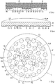
- a laminated sliding member 1 is comprised of a base body 4 having one flat surface 3 which is circular in a plan view and a solid lubricant layer 5 adhered to the flat surface 3 of the base body 4 and having a sliding surface 2 which is circular in a plan view.
- the base body 4 which has a laminate 6 having the flat surface 3 and formed by superposing and mutually joining a plurality of polyester fiber woven fabrics impregnated with a resol-type phenolic resin containing a polytetrafluoroethylene resin, has a plurality of recessed portions 13 which are disposed in the laminate 6 by being located in an area exclusive of and radially inwardly of an annular flat surface 8, i.e., an annular outer flat surface of the flat surface 3, bounded by an outer peripheral edge 7 of the flat surface 3 of the laminate 6 and by a circle 9 located in such a way as to be spaced apart a desired distance W radially inwardly from the outer peripheral edge 7 and serving as an imaginary line similar in shape to the outer peripheral edge 7, and which are open at a circular flat surface 3a, i.e., an inner flat surface of the flat surface 3 surrounded by the circle 9, and are each defined by an opening plane 10 which is circular in a plan view at the circular flat surface 3a, a cylindrical wall surface
- the flat surface 3 constituted by the circular flat surface 3a and the annular flat surface 8, the cylindrical wall surface 11, and the circular bottom wall surface 12 have hair-like fluff 16 of the polyester fiber woven fabric, and the solid lubricant layer 5 is adhered to the flat surface 3, which is constituted by the circular flat surface 3a and the annular flat surface 8 in the laminate 6, in such a manner as to be formed integrally with the fluff 16 in mixed form and to extend to the recessed portions 13 in the laminate 6.
- the distance (radial width) W is 0.5 to 1.1 times a diameter d of the opening plane 10 of the recessed portion 13, and the plurality of recessed portions 13 are arranged by respectively having centers O1, O2, and O3 on a plurality of imaginary concentric circles P1, P2, and P3 which are imaginary concentric annular lines having a center O, i.e., a circular plan figure center of gravity of the flat surface 3 of the laminate 6, and equal intervals T between each other in a radially outward direction from the center O.
- the equal interval T is 1.5 to 1.8 times the diameter d of the opening plane 10
- the imaginary circle 9 constitutes an envelope of the cylindrical wall surfaces 11 defining the 18 recessed portions 13 arranged by respectively having centers O3 on the concentric circle P3.
- the resol-type phenolic resin impregnated in the polyester fiber woven fabric i.e., a reinforcing base material
- a phenolic compound containing 50 to 100 mol% of bisphenol A and a formaldehyde compound in the presence of an amine as a catalyst is synthesized from a phenolic compound containing 50 to 100 mol% of bisphenol A and a formaldehyde compound in the presence of an amine as a catalyst, and has a number average molecular weight Mn of 500 to 1000 as measured by gel permeation chromatography (GPC) and a degree of dispersion Mw/Mn of 2.5 to 15 as defined by the ratio of the weight average molecular weight Mw to the number average molecular weight Mn.
- GPC gel permeation chromatography
- the ratio of bisphenol A (C 15 H 16 O 2 ) among phenolic compounds is set to 50 to 100 mol%. This is the ratio of the number of moles of bisphenol A to the combined number of moles of total phenolic compounds charged at the start of synthesis.
- the resol-type phenolic resin after the synthesis has the number average molecular weight Mn of 500 to 1000 as measured by GPC and the degree of dispersion Mw/Mn of the molecular weight distribution of 2.5 to 15.
- affinity with the polyester fiber woven fabric serving as the reinforcing base material is improved remarkably; therefore, adhesiveness to the polyester fiber woven fabric is excellent without subjecting the polyester fiber woven fabric to surface treatment.
- the laminate 6 formed by using such polyester fiber woven fabrics has high rigidity, excels in mechanical strength, and has extremely low swellability in use in a wet atmosphere such as in water.
- the resol-type phenolic resin if bisphenol A is less than 50 mol%, sufficient affinity with the polyester fiber woven fabric cannot be obtained, and sufficient adhesiveness to the polyester fiber woven fabric cannot be obtained.
- the resol-type phenolic resin should preferably have the number average molecular weight Mn of 500 to 1000 as measured by GPC and the degree of dispersion Mw/Mn of 2.5 to 15.
- the number average molecular weight Mn is less than 500, even if affinity with the polyester fiber woven fabric is satisfactory, a decline in mechanical strength is brought about, whereas if the number average molecular weight Mn exceeds 1000, the viscosity of the resol-type phenolic resin becomes excessively high, and impregnation into the polyester fiber woven fabric becomes difficult. Further, if the degree of dispersion Mw/Mn is less than 2.5, sufficient adhesiveness to the polyester fiber woven fabric cannot be obtained, whereas if the degree of dispersion Mw/Mn exceeds 15, impregnation into the polyester fiber woven fabric becomes difficult in the same way as the case where the number average molecular weight Mn exceeds 1000.
- a phenolic compound or compounds other than bisphenol A are included.
- the phenolic compounds other than bisphenol A it is possible to cite phenol, cresol, ethylphenol, aminophenol, resolcinol, xylenol, butylphenol, trimethylphenol, catechol, phenylphenol, and the like. Among them, phenol is preferably used by virtue of its characteristics.
- the phenolic compounds other than bisphenol A may be used singly or as a mixture of two or more kinds.
- formaldehyde compounds it is possible to cite formalin, paraformaldehyde, salicylaldehyde, benzaldehyde, p-hydroxybenzaldehyde, and the like.
- formalin and paraformaldehyde are preferably used in view of readiness of synthesis.
- the formaldehyde compounds may be used singly or as a mixture of two or more kinds.
- amines used as the catalyst it is possible to cite triethylamine, triethanolamine, benzyldimethylamine, aqueous ammonia, and the like. Among them, triethylamine and aqueous ammonia are preferably used in view of readiness of synthesis.
- the content of resol-type phenolic resin contained in the laminate 6 is preferably 40 to 60% by mass. If the content of resol-type phenolic resin is less than 40% by mass, the moldability (manufacturing) of the laminated sliding member 1 is adversely affected, whereas if the content exceeds 60% by mass, the mechanical strength of the laminate 6 is caused to decline.
- PTFE polytetrafluoroethylene resin
- high molecular weight PTFE a molding powder for molding
- low molecular weight PTFE PTFE
- the molecular weight of the high molecular weight PTFE is, for example, approximately 700,000 to 10,000,000 or even higher, while the molecular weight of the low molecular weight PTFE is, for example, approximately 10,000 to 500,000 or thereabouts.
- the low molecular weight PTFE is primarily used as an additive and is readily crushable and highly dispersible.
- TLP-10F (tradename)
- Lubron L-5 (tradename)” etc. manufactured by Daikin Industries, Ltd.
- Fluon L150J (tradename),” “Fluon L169J (tradename),” etc. manufactured by Asahi Glass Co., Ltd.
- KTL-8N (tradename),” "KTL-2N (tradename),” etc. manufactured by Kitamura Ltd.
- a powder of the low molecular weight PTFE is preferable in view of uniform dispersion and suppression of void formation when mixed with the resol-type phenolic resin.
- the average particle size of the PTFE powder is preferably 1 to 50 ⁇ m, and more preferably 1 to 30 ⁇ m, in view of ensuring uniform dispersion and preventing voids form being formed.
- the content of PTFE contained in the laminate 6 10 to 30% by mass is appropriate. If the content of PTFE is less than 10% by mass, an effect cannot be obtained in improving the friction and abrasion characteristics, whereas if the content exceeds 30% by mass, the viscosity of resin increases at the time of molding, may form voids, may reduce adhesiveness of the resol-type phenolic resin, may reduce the strength as the laminated sliding member 1, and may thereby induce interlayer delamination.
- the polyester fiber woven fabric is formed into a woven fabric by spinning polyester fiber by a conventional method.
- the polyester fiber is generally obtained by polycondensation of a dicarboxylic acid component and a diol component.
- the dicarboxylic acid component it is possible to cite terephthalic acid, isophthalic acid, naphthalene-2, 6-dicarboxylic acid, and the like; and as the diol component, it is possible to cite ethylene glycol, hydroquinone, bisphenol A, biphenyl, and the like.
- p-hydroxybenzoic acid 2-oxy-6-naphthoic acid, and the like.
- a typical polyester fiber is obtained from polyethylene terephthalate (PET) having terephthalic acid and ethylene glycol as principle components.
- PET polyethylene terephthalate
- a typical polyester fiber is low in moisture absorption and water absorption properties and has a moisture content of 0.4 to 0.5%, whereas cotton normally has a moisture content of 8 to 9%.
- the form of the spun yarn may be either a filament yarn made by twisting long fibers or a spun yarn made by twisting short fibers.
- the weave structure of the woven fabric is not particularly limited, and it is possible to adopt any one of three basic weaves including plain weave, twill weave, and satin weave, one of modified or derivative weaves including modified plain weave, modified twill weave, and modified satin weave, and a mixed weave of one of three basic waves and a modified weave.
- the content of the polyester fiber woven fabric contained in the laminate 6 is preferably 25 to 35% by mass. If the content of the polyester fiber woven fabric is less than 25% by mass, a sufficient reinforcing effect cannot be obtained when used for the laminated sliding member 1, whereas if the content exceeds 35% by mass, the moldability (manufacturing) of the laminated sliding member 1 is adversely affected.
- the resol-type phenolic resin contained in the laminate 6 is set to 40 to 60% by mass, the polytetrafluoroethylene resin is set to 10 to 30% by mass, and the polyester fiber woven fabric is set to 25 to 35% by mass, it is possible to obtain a laminate which is excellent in all of moldability, mechanical strength, and friction and abrasion characteristics
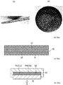
- a prepreg (resin base) for the laminate 6 can be fabricated, for example, by using a manufacturing apparatus illustrated in Fig. 4 .
- a reinforcing base material 18 which is composed of a polyester fiber woven fabric wound up on an uncoiler 17 is fed by a feed roller 19 to a container 21 which contains a mixed liquid 20 composed of PTFE powder and a resol-type phenolic resin varnish with PTFE powder uniformly dispersed therein.
- the mixed liquid 20 is coated on the surface of the reinforcing base material 18, as the reinforcing base material 18 is allowed to pass through the mixed liquid 20 contained in the container 21 with the aid of guide rollers 22 and 23 provided in the container 21.
- the reinforcing base material 18 coated with the mixed liquid 20 is fed by the feed roller 19 to compression rolls 24 and 25, where the mixed liquid 20 coated on the surface of the reinforcing base material 18 is allowed to impregnate into voids in the fiber texture by the compression rolls 24 and 25.
- a drying oven 26 the solvent is vaporized from the reinforcing base material 18 coated and impregnated with the mixed liquid 20, and a reaction of the resol-type phenolic resin varnish concurrently proceeds, thereby fabricating a moldable prepreg (resin base) 27 for the laminate 6.
- the solid content of the resol-type phenolic resin varnish prepared by dissolving the resol-type phenolic resin into a volatile solvent is approximately 30 to 65% by mass of the whole resin varnish, viscosity of the resin varnish is preferably 800 to 5000 cP, and particularly preferably 1000 to 4000 cP.
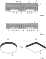
- such a prepreg 27 is cut into a square shape in such a number of sheets as to ensure a desired finished thickness.
- the predetermined number of cut sheets of prepreg 27 are stacked and laminated in a square recess 29 of a die 28 of a heat pressing machine, and the stack is subsequently heated to a temperature of 140 to 160° C in the die 28 and is pressure molded under a pressure of 4.9 to 7 MPa in the laminated direction by a ram 30, thereby obtaining a square laminated molding 31 in which the laminated prepregs 27 are joined to each other in a fused state, as shown in part (a) of Fig. 7 .
- the laminated molding 31 is subjected to machining to form a disk-shaped laminate 6, as shown in part (b) of Fig. 7 .
- the disk-shaped laminate 6 thus formed has high rigidity, excels in mechanical strength, and excels in friction and abrasion characteristics.
- the laminate 6 can be adopted in a wide variety of applications under dry frictional conditions, grease lubricated conditions, water lubricated conditions, and the like.
- the square prepregs 27 shown in part (a) of Fig. 5 may be subjected to machining to fabricate disk-shaped prepregs 27a, as shown in part (b) of Fig.
- the stack may be subsequently heated to a temperature of 140 to 160° C in the die 28 and may be pressure molded under a pressure of 4.9 to 7 MPa in the laminated direction by the ram 30, thereby obtaining a circular laminate 6, as shown in part (b) of Fig. 7 .
- the recessed portions 13 are formed in a surface 15 serving as the flat surface 3 of the disk-shaped laminate 6 by machining using an end mill, a drilling machine, or the like. Further, the slender hair-like fluff 16 of the polyester fiber woven fabric is formed on surfaces constituting the cylindrical wall surface 11 and the circular bottom wall surface 12 which define each of the recessed portions 13. Also, the slender hair-like fluff 16 of the polyester fiber woven fabric is formed on the surface 15 constituting the flat surface 3 after the surface 15 is subjected to surface roughening treatment by polishing or sandblasting.
- the solid lubricant layer 5 which is adhered to the flat surface 3 of the laminate 6 in such a manner as to extend to the recessed portions 13 by being formed integrally with the fluff 16 in mixed form, contains a hydrocarbon-based wax, melamine cyanurate, PTFE, and a phosphate.
- the hydrocarbon-based wax mainly imparts a low friction property to the solid lubricant layer 5, and the hydrocarbon-based wax is selected from at least one of a paraffin-based wax having a carbon number of about 24 or more, a olefin-based wax having a carbon number of about 26 or more, alkylbenzene having a carbon number of about 28 or more, and microcrystalline wax.
- hydrocarbon-based wax As specific examples the hydrocarbon-based wax, it is possible to cite paraffin wax "150 (tradename)” and microcrystalline wax "Hi-Mic-1080 (tradename)” both manufactured by Nippon Seiro Co., Ltd.; polyethylene wax “Licowax PE 520 (tradename)” manufactured by Clariant Japan K.K.; a mixture of polyethylene wax and paraffin wax “Goddess Wax (tradename)” manufactured by Nikko Fine Products Co., Ltd., and the like.
- the compounding ratio of the hydrocarbon-based wax is preferably 20 to 40% by mass. If the compounding ratio is less than 20% by mass, the low friction property cannot be sufficiently exhibited, whereas if the compounding ratio exceeds 40% by mass, it results in weakening the joining force between the solid lubricant layer 5 and the surface 15.
- Melamine cyanurate is an adduct of melamine with cyanuric acid or isocyanuric acid, and it has such a structure that the melamine molecules having a 6-membered ring structure and cyanuric acid (or isocyanuric acid) molecules having a 6-membered ring structure are arranged in a planar form through a hydrogen bond to form overlapped layers bonded to each other by a weak bonding force, so that the melamine cyanurate is considered to have a cleavage property similar to that of molybdenum disulfide or graphite.
- This melamine cyanurate serves to improve particularly the wear resistance and load-bearing capacity of the solid lubricant layer 5.
- the melanine cyanurate is not particularly limited, and it is possible to use a generally known melanine cyanurate.
- a generally known melanine cyanurate For example, it is possible to suitably use those described in JP-B-1970-5595 , JP-B-1986-34430 , JP-A-1993-310716 , JP-A-1995-224049 , and the like.
- MCA-1 tradename
- the compounding ratio of the melanine cyanurate is preferably 15 to 30% by mass. If the compounding ratio is less than 15% by mass, it is impossible to obtain desired effects in improving the wear resistance and load-bearing capacity, whereas if the compounding ratio exceeds 30% by mass, the wear resistance and load-bearing capacity are lowered to the contrary.
- the compounding ratio of PTFE is preferably 20 to 50% by mass. If the compounding ratio is less than 20% by mass, the low friction property cannot be sufficiently imparted to the solid lubricant layer 5, whereas if the compounding ratio exceeds 50% by mass, the ratio of exposure of the solid lubricant layer 5 on the sliding surface 2 becomes large, with the result that the wear resistance of the solid lubricant layer 5 is lowered, the shape retainability deteriorates, and the strength of the solid lubricant layer 5 is lowered.
- the phosphate per se does not exhibit lubricity, but in sliding between the solid lubricant layer 5 and the mating member the phosphate serves to promote the film formability of a lubricating film of the solid lubricant layer 5 on the surface of the mating member.
- the phosphates it is possible to cite tertiary phosphates, secondary phosphates, pyrophosphates, phosphites, and metaphosphates of alkali metals or alkali earth metals.
- trilithium phosphate dilithium hydrogenphosphate, lithium pyrophosphate, tricalcium phosphate, calcium monohydrogenphosphate, calcium pyrophosphate, lithium metaphosphate, magnesium metaphosphate, calcium metaphosphate, and the like.
- the compounding ratio of the phosphate is preferably 5 to 15% by weight.
- the phosphate may fail to exhibit a sufficient effect of promoting the formation of a lubricating film on the surface of the mating member, whereas if the compounding ratio exceeds 15% by mass, the amount of lubricating film transferred and attached to the surface of the mating member tends to be excessively large, so that the wear resistance of the solid lubricant layer 5 is lowered to the contrary.
- the solid lubricant layer 5 which is composed of a lubricating composition including 20 to 40% by mass of a hydrocarbon-based wax, 10 to 30% by mass of melamine cyanurate, 20 to 50% by mass of PTFE, and 5 to 15% by mass of a phosphate, is obtained as follows: predetermined amounts of the above-described components are mixed in a mixing machine, such as a Henschel mixer, a super mixer, a ball mill, or a tumbler mixer; the mixture thus obtained is molded to fabricate a disk-shaped molding; and this molding is placed on the flat surface 3 of the laminate 6 and is, together with the laminate 6, subjected to compression molding to allow the solid lubricant layer 5 to be formed on the flat surface 3 of the laminate 6 in such a manner as to be filled in the recessed portions 13 and to be formed integrally with the slender hair-like fluff 16 of the polyester fiber woven fabric in mixed form, thereby forming the laminated sliding member 1.
- a mixing machine such as a He
- the laminated sliding member 1 may have the base body 4 which includes, in addition to the laminate 6, another laminate 32 which is integrally joined to another circular surface 41 of the laminate 6 and in which a plurality of sheets of inorganic fiber woven fabric or organic fiber woven fabric are superposed one upon another and joined to each other.
- the laminate 32 shown in Fig. 9 is fabricated by a manufacturing apparatus similar to that shown in Fig. 6 . Namely, a reinforcing base material 33 composed of an organic fiber woven fabric or an inorganic fiber woven fabric wound up on the uncoiler 17 is fed by the feed roller 19 to the container 21 which contains a resol-type phenolic resin varnish 34.
- the resol-type phenolic resin varnish 34 is coated on the surface of the reinforcing base material 33, as the reinforcing base material 33 is allowed to pass through the resol-type phenolic resin varnish 34 contained in the container 21 with the aid of guide rollers 22 and 23 provided in the container 21.
- the reinforcing base material 33 coated with the resol-type phenolic resin varnish 34 is fed by the feed roller 19 to the compression rolls 24 and 25, where the resol-type phenolic resin varnish 34 is allowed to impregnate into voids in the fiber texture by the compression rolls 24 and 25.
- the solvent is vaporized from the reinforcing base material 33 coated and impregnated with the resol-type phenolic resin varnish 34, and a reaction of the resol-type phenolic resin varnish 34 concurrently proceeds, thereby fabricating a moldable prepreg 35 for the laminate 32.
- an inorganic fiber woven fabric such as a glass fiber woven fabric and a carbon fiber woven fabric or an organic fiber woven fabric such as an aramid resin fiber woven fabric (a copolyparaphenylene-3, 4'-oxydiphenyleneterephthalic amide resin fiber woven fabric, e.g., "Technora (registered trademark)” manufactured by Teijin Techno Products Limited) is used.
- aramid resin fiber woven fabric a copolyparaphenylene-3, 4'-oxydiphenyleneterephthalic amide resin fiber woven fabric, e.g., "Technora (registered trademark)" manufactured by Teijin Techno Products Limited
- the prepregs 27 or 27a for the laminate 6 are placed on an upper surface thereof, and an assembly thereof is heated to a temperature of 140 to 160° C in the die 28 and is pressure molded under a pressure of 4.9 to 7 MPa in the laminated direction by the ram 30, thereby obtaining a multilayered molding which is square or circular in a plan view.
- a multilayered molded member 36 is fabricated in which the laminated prepregs 27 or 27a for the laminate 6 and prepregs 35 or 35a for the laminate 32 are joined to each other in a fused state, as shown in Fig. 11 .
- the multilayered molded member 36 thus fabricated includes the laminate 32 serving as a metal backing formed of an inorganic fiber woven fabric or an organic fiber woven fabric and the laminate 6 which is integrally joined to the one surface 37 of the laminate 32.
- the recessed portions 13 and the fluff 16 are formed on the flat surface 3 of the laminate 6 in the same way as described above to form the base body 4, and the solid lubricant layer 5 is formed on this base body 4, thereby fabricating the laminated sliding member 1, as shown in Fig. 9 .
- the other surface 41 of the laminate 6 and another surface 41a of the laminate 32 are formed into flat surfaces which are circular in a plan view
- disk-shaped prepregs 27a having different diameters may be stacked and laminated in a predetermined number and pressurized in the same way as described above, to thereby form the base body 4 provided with the laminate 6 which is circular in a plan view and has a convex spherical other surface 41b, as shown in Fig. 2 .
- a prepreg for the laminate was used which was composed of 30% by mass of a polyester fiber woven fabric fabricated by a plain weave by using a spun yarn of No. 20 cotton count and setting the thread density to 43 ends/inch for the warp and to 42 picks/inch for the weft, 23% by mass of PTFE, and the balance of 47% by mass of a resol-type phenolic resin.
- This prepreg was cut into a square shape whose length of one side was 200 mm, and 18 sheets of this prepreg were stacked and in the recess of the die of the heat pressing machine shown in Fig. 6 and having a square recess whose length of one side was 200.5 mm.
- This laminated assembly was then heated for 10 minutes to a temperature of 160° C in the die and was pressure molded under a pressure of 7 MPa in the laminated direction, thereby obtaining a square laminated molding.
- the laminated molding thus obtained was subjected to machining, and a laminate having a diameter of 200 mm and a thickness of 8 mm and circular in a plan view was thereby fabricated.
- Slender hair-like fluff of the polyester fiber woven fabric of the reinforcing base body was formed on the cylindrical inner wall surface and the circular bottom wall surface defining each of the recessed portions formed by this end mill machining.
- the one flat surface of the laminate where these recessed portions were formed was subjected to polishing, and slender hair-like fluff of the polyester fiber woven fabric was formed on that one flat surface.
- the imaginary circle constituted an envelope of the cylindrical wall surfaces defining the 42 recessed portions having their centers on the concentric circle with the largest diameter.
- This disk-shaped sheet was placed on the one flat surface of the laminate having the slender hair-like fluff of the polyester fiber woven fabric on the one flat surface and on the cylindrical inner wall surface and the circular bottom wall surface defining each of the 169 recessed portions, and was subjected to compression molding to allow a solid lubricant layer to be formed on the one flat surface of the laminate in such a manner as to be filled in the recessed portions and to be formed integrally with the slender hair-like fluff of the polyester fiber woven fabric in mixed form, thereby forming the laminated sliding member 1.
- Example 2 In the same way as in Example 1, a laminate having a diameter of 200 mm and a thickness of 8 mm and circular in a plan view was fabricated.
- Example 2 In the same way as in Example 1, on the one flat surface of the laminate which was circular in a plan view, a total of 169 recessed portions with a depth of 0.9 mm, including 6, 12, 18, 24, 30, 36, and 42 recessed portions arranged respectively on imaginary concentric circles located at equal intervals of 13.8 mm and one recessed portion at the center, were formed by end mill machining inside an imaginary circle located at the distance W of 4.5 mm (0.5-fold the diameter of the opening of the recessed portion) radially inwardly from the outer peripheral edge. Thereafter, in the same way as in Example 1, a solid lubricant layer was formed on the one flat surface of the laminate having a total of 169 recessed portions, thereby forming the laminated sliding member 1.
- Example 2 In the same way as in Example 1, a laminate which was circular in a plan view and had a diameter of 200 mm and a thickness of 8 mm was fabricated.
- a total of 169 recessed portions with a depth of 0.9 mm including 6, 12, 18, 24, 30, 36, and 42 recessed portions arranged respectively on concentric circles equally spaced at 14.0 mm intervals and one recessed portion at the center O, were formed by end mill machining inside an imaginary circle spaced apart at the distance W of 2.5 mm (0.31-fold the diameter of the opening of the recessed portion) radially inwardly from the outer peripheral edge.
- a solid lubricant layer was formed on the one flat surface of the laminate having a total of 169 recessed portions, thereby forming the laminated sliding member 1 shown in Fig. 18 .
- the laminated sliding member of Examples 1 and 2 since the annular flat surface had the width (distance W) 0.5-fold to 1.06-fold the opening diameter of the recessed portion, even when the laminated sliding member is subjected to high-velocity sliding during an earthquake, e.g., high-velocity sliding of 60 cm/sec, the laminated sliding member exhibits excellent friction performance, and defects including damage such as cracking and chipping, deformation, and the like do not occur at the sliding surface.
- a sliding bearing 39 incorporating the above-described laminated sliding member 1 is comprised of a lower shoe 52 having a recessed portion 51 which is circular in a plan view and is open at one surface 40 thereof; a rubber elastomer 54 which is circular in a plan view, is accommodated tightly in the recessed portion 51 of the lower shoe 52, and has an annular notched stepped portion 53 at an outer peripheral edge of an upper surface thereof; an annular ring 55 fitted and fixed in the notched stepped portion 53; an intermediate plate 58 which is circular in a plan view, is disposed on the upper surface of the rubber elastomer 54 so as to be swingable and rotatable relative to the lower shoe 52, and has a circular recessed portion 57 in an upper surface 56 thereof; the laminated sliding member 1 fitted and fixed in the recessed portion 57 of the intermediate plate 58; and an upper shoe 60 having fixed thereon a slide plate 59 which is brought into slidable contact with the sliding surface 2 of the
- the annular ring 55 has a synthetic resin-made protective ring 62 which is inserted and fitted in the notched stepped portion 53 of the rubber elastomer 54 and a metallic compression ring 63 which is disposed on an upper surface of the protective ring 62 and is inserted and fitted in the annular notched stepped portion 53 of the rubber elastomer 54.
- the annular ring 55 is adapted to prevent the damage of the rubber elastomer 54 by preventing an outer peripheral edge portion of the rubber elastomer 54 from jutting out from a clearance 64 between an outer peripheral surface of the intermediate plate 58 and a wall surface at the recessed portion 51 of the lower shoe 52.
- a sliding bearing 71 in accordance with another embodiment shown in Fig. 17 is comprised of a lower shoe 74 having a concave spherical surface 73 on one surface 72 thereof; the laminated sliding member 1 which has the sliding surface 2 of the solid lubricant layer 5 and the convex spherical surface 41b, and is, at the surface 41b thereof, brought into slidable contact with the concave spherical surface 73; and the upper shoe 60 having fixed thereon the slide plate 59 which is brought into slidable contact with the sliding surface 2 of the laminated sliding member 1.
- a plurality of anchor bolts 81 which are embedded in and fixed to a lower structure of a bridge pier or the like, are fixed to the lower surface of each of the lower shoes 52 and 74, while a plurality of anchor bolts 82, which are embedded in and fixed to an upper structure of the bridge pier or the like, are fixed to the upper shoe 60.
- the sliding bearings 39 and 71 exhibit excellent friction performance even when subjected to high-velocity sliding of, e.g., 60 cm/sec during an earthquake.
Landscapes
- Engineering & Computer Science (AREA)
- Chemical & Material Sciences (AREA)
- Architecture (AREA)
- Mechanical Engineering (AREA)
- Oil, Petroleum & Natural Gas (AREA)
- General Chemical & Material Sciences (AREA)
- Organic Chemistry (AREA)
- Chemical Kinetics & Catalysis (AREA)
- Civil Engineering (AREA)
- Structural Engineering (AREA)
- Environmental & Geological Engineering (AREA)
- General Engineering & Computer Science (AREA)
- Business, Economics & Management (AREA)
- Emergency Management (AREA)
- Electromagnetism (AREA)
- Physics & Mathematics (AREA)
- Inorganic Chemistry (AREA)
- Sliding-Contact Bearings (AREA)
- Buildings Adapted To Withstand Abnormal External Influences (AREA)
- Vibration Prevention Devices (AREA)
- Lubricants (AREA)
- Laminated Bodies (AREA)
Claims (13)
- Élément coulissant stratifié (1) comprenant : un corps de base (4) ayant une pluralité de parties évidées (13) dans une surface plate de celui-ci ; et une couche de lubrifiant solide (5) collée sur au moins la surface plate dudit corps de base (4) de sorte à s'étendre jusqu'aux parties évidées (13) dudit corps de base (4),
ledit corps de base (4) ayant un stratifié (6) ayant la surface plate et formé par superposition et jonction mutuelle d'une pluralité d'étoffes tissées en fibres de polyester imprégnées d'une résine phénolique de type résol contenant une résine de polytétrafluoroéthylène,
la pluralité de parties évidées (13) étant disposées dans le stratifié (6) en étant situées dans une zone ne comprenant pas une surface plate externe annulaire de la surface plate du stratifié (6) et vers l'intérieur de celle-ci, délimitée par un bord périphérique externe de la surface plate du stratifié (6) et par une ligne imaginaire située de sorte à être espacée d'une distance prédéterminée vers l'intérieur du bord périphérique externe et de forme similaire au bord périphérique externe, la pluralité de parties évidées (13) étant ouvertes au niveau d'une surface plate interne de la surface plate du stratifié (6) entourée par la ligne imaginaire, chaque partie évidée de la pluralité de parties évidées (13) étant définie par une surface de paroi cylindrique (11) dans le stratifié (6) et une surface de paroi inférieure circulaire (12) dans le stratifié (6), caractérisé en ce que,
la surface plate du stratifié (6) constituée par la surface plate interne et la surface plate externe annulaire, les surfaces de paroi cylindrique (11) et les surface de paroi inférieure circulaire (12) possèdent un duvet de type poil (16) de l'étoffe tissée en fibres de polyester, et ladite couche de lubrifiant solide (5) est collée à au moins la surface plate du stratifié (6) de sorte à être formée solidairement avec le duvet (16) sous une forme mixte et à s'étendre jusqu'aux parties évidées (13) dans le stratifié (6),
la distance prédéterminée entre le bord périphérique externe de la surface plate du corps de base (4) et la ligne imaginaire étant égale à 0,5 à 1,1 dois un diamètre d'ouverture de la partie évidée (13). - Élément coulissant stratifié (1) selon la revendication 1, dans lequel le corps de base (4) possède en outre un autre stratifié (32) qui est joint solidairement à une autre surface du stratifié (6) et dans lequel une pluralité de feuilles d'étoffe tissée en fibres inorganiques ou d'étoffe tissée en fibres organiques sont superposées les unes sur les autres et jointes les unes aux autres.
- Élément coulissant stratifié (1) selon la revendication 1 ou 2, dans lequel la pluralité de parties évidées (13) sont agencées en ayant respectivement leurs centres sur une pluralité de lignes annulaires concentriques imaginaires qui ont un centre sur la surface plate du stratifié (6) et des intervalles égaux entre elles dans une direction vers l'extérieur depuis le centre, et sont de forme similaire au bord périphérique externe.
- Élément coulissant stratifié (1) selon la revendication 3, dans lequel la surface plate dudit corps de base (4) est circulaire en vue en plan, la pluralité de lignes annulaires concentriques imaginaires sont constituées par une pluralité de cercles concentriques imaginaires, et sur un ne (n étant un entier positif) cercle concentrique imaginaire à partir du centre de la surface plate parmi la pluralité de cercles concentriques imaginaires, un nombre égal à 6 x n de parties évidées (13) sont respectivement agencées selon des angles centraux mutuellement égaux entre des parties évidées (13) adjacentes vis-à-vis du ne cercle concentrique imaginaire.
- Élément coulissant stratifié (1) selon l'une quelconque des revendications 1 à 4, dans lequel la surface plate est circulaire en vue en plan, la ligne imaginaire est constituée par un cercle, la surface plate externe est de forme circulairement annulaire, et la surface plate interne est de forme circulaire.
- Élément coulissant stratifié (1) selon l'une quelconque des revendications 1 à 5, dans lequel le stratifié (6) comprend 40 à 60 % en masse d'une résine phénolique de type résol, 10 à 30 % en masse d'une résine de polytétrafluoroéthylène, et 25 à 35 % en masse d'une étoffe tissée en fibres de polyester.
- Élément coulissant stratifié (1) selon l'une quelconque des revendications 1 à 6, dans lequel ladite couche de lubrifiant solide (5) contient une cire à base d'hydrocarbure, une résine de polytétrafluoroéthylène, du cyanurate de mélamine et un phosphate, ou
ladite couche de lubrifiant solide (5) contenant 20 à 40 % en masse de la cire à base d'hydrocarbure, 20 à 50 % en masse de la résine de polytétrafluoroéthylène, 15 à 30 % en masse du cyanurate de mélamine et 5 à 15 % en masse du phosphate. - Élément coulissant stratifié (1) selon l'une quelconque des revendications 1 à 7, dans lequel ledit corps de base (4) possède une autre surface plate, ou
dans lequel ledit corps de base (4) possède une autre surface plate, et
dans lequel l'autre surface plate est circulaire en vue en plan. - Élément coulissant stratifié (1) selon l'une quelconque des revendications 1 à 7, dans lequel ledit corps de base (4) possède une autre surface sphérique convexe, ou
dans lequel ledit corps de base (4) possède une autre surface sphérique convexe, et
dans lequel l'autre surface sphérique convexe est circulaire en vue en plan. - Palier coulissant (39) comprenant : un sabot inférieur (52) ayant une partie évidée qui est ouverte au niveau d'une surface (40) de celle-ci ; un élastomère de caoutchouc qui est logé étroitement dans la partie évidée dudit sabot inférieur (52), et possède une partie étagée à encoche annulaire (53) au niveau d'un bord périphérique externe d'une surface supérieure de celle-ci ; une bague annulaire (55) adaptée et fixée dans la partie étagée à encoche (53) ; une plaque intermédiaire qui est disposée sur la surface supérieure dudit élastomère de caoutchouc de façon à pouvoir basculer et tourner par rapport audit sabot inférieur (52), et possède une partie évidée dans une surface supérieure de celle-ci ; l'élément coulissant stratifié (1) selon la revendication 8 adapté et fixé dans la partie évidée de ladite plaque intermédiaire ; et un sabot supérieur (60) sur lequel est fixée une plaque de coulissement (59) qui est mise en contact coulissant avec ladite couche de lubrifiant solide (5) de l'élément coulissant stratifié (1).
- Palier coulissant (39) selon la revendication 10, dans lequel la partie évidé dudit sabot inférieur (52), ledit élastomère de caoutchouc et ladite plaque intermédiaire sont circulaires en vue en plan.
- Palier coulissant (39) selon la revendication 10 ou 11, dans lequel ladite bague annulaire (55) possède une bague de protection constituée de résine de synthèse (62) qui est adaptée dans la partie étagée à encoche annulaire (53) dudit élastomère de caoutchouc et une bague de compression métallique (63) qui est disposée sur une surface supérieure de la bague de protection (62) et est adaptée dans la partie étagée à encoche annulaire (53) dudit élastomère de caoutchouc.
- Palier coulissant (71) comprenant : un sabot inférieur (74) ayant une surface sphérique concave (73) sur une surface (72) de celui-ci ; l'élément coulissant stratifié (1) selon la revendication 9 qui est disposé sur ledit sabot inférieur (74) de sorte qu'une autre surface sphérique convexe (41b) de celui-ci soit mise en contact avec la surface sphérique concave (73) dudit sabot inférieur (74) ; et un sabot supérieur (60) sur lequel est fixée une plaque de coulissement (59) qui est mise en contact coulissant avec ladite couche de lubrifiant solide (5) de l'élément coulissant stratifié (1).
Applications Claiming Priority (2)
| Application Number | Priority Date | Filing Date | Title |
|---|---|---|---|
| JP2013145923A JP6143588B2 (ja) | 2013-07-11 | 2013-07-11 | 積層すべり部材及びこの積層すべり部材を使用したすべり支承 |
| PCT/JP2014/003346 WO2015004865A1 (fr) | 2013-07-11 | 2014-06-23 | Élément de glissement stratifié et palier lisse faisant appel audit élément de glissement stratifié |
Publications (3)
| Publication Number | Publication Date |
|---|---|
| EP3021002A1 EP3021002A1 (fr) | 2016-05-18 |
| EP3021002A4 EP3021002A4 (fr) | 2017-02-15 |
| EP3021002B1 true EP3021002B1 (fr) | 2019-07-31 |
Family
ID=52279575
Family Applications (1)
| Application Number | Title | Priority Date | Filing Date |
|---|---|---|---|
| EP14822878.6A Active EP3021002B1 (fr) | 2013-07-11 | 2014-06-23 | Élément de glissement stratifié et palier lisse faisant appel audit élément de glissement stratifié |
Country Status (6)
| Country | Link |
|---|---|
| US (1) | US9732538B2 (fr) |
| EP (1) | EP3021002B1 (fr) |
| JP (1) | JP6143588B2 (fr) |
| CN (1) | CN105378329A (fr) |
| TW (1) | TWI628340B (fr) |
| WO (1) | WO2015004865A1 (fr) |
Families Citing this family (7)
| Publication number | Priority date | Publication date | Assignee | Title |
|---|---|---|---|---|
| DE102015115385B4 (de) * | 2015-09-11 | 2019-08-01 | Miba Industrial Bearings Germany Gmbh | Kippsegment und Kippsegmentgleitlager |
| FR3061750B1 (fr) * | 2017-01-10 | 2019-08-23 | Renault S.A.S | Butee fixe d'un systeme de butees fixe et tournante destine a supporter une charge axiale. |
| CN106759929A (zh) * | 2017-03-10 | 2017-05-31 | 清华大学 | 摩擦滑移支座 |
| US10683463B2 (en) | 2017-06-13 | 2020-06-16 | Ggb, Inc. | Solid lubricant compositions and bearings incorporating the same |
| JP6902972B2 (ja) * | 2017-09-14 | 2021-07-14 | オイレス工業株式会社 | 免震装置 |
| GB2569158B (en) * | 2017-12-07 | 2020-08-05 | Mahle Engine Systems Uk Ltd | Bearing material, bearing element and method |
| JP7092607B2 (ja) * | 2018-08-09 | 2022-06-28 | オイレス工業株式会社 | すべり支承 |
Family Cites Families (20)
| Publication number | Priority date | Publication date | Assignee | Title |
|---|---|---|---|---|
| US3151015A (en) | 1961-01-30 | 1964-09-29 | American Brake Shoe Co | Bearings |
| JPS5455588A (en) | 1977-10-04 | 1979-05-02 | Asahi Chem Ind Co Ltd | Production of melamine cyanurate |
| JP3127936B2 (ja) | 1992-05-08 | 2001-01-29 | 日産化学工業株式会社 | メラミンシアヌレートの製造方法 |
| JP2751815B2 (ja) | 1994-02-08 | 1998-05-18 | 日産化学工業株式会社 | 表面処理されたメラミンシアヌレート粉末およびその製造方法 |
| JPH10280320A (ja) * | 1997-04-10 | 1998-10-20 | Yokohama Rubber Co Ltd:The | 橋梁用ゴム状弾性支承工法及びその橋梁用ゴム状弾性支承装置 |
| JPH11182095A (ja) | 1997-12-17 | 1999-07-06 | Ntn Corp | 免震装置 |
| JPH11351325A (ja) * | 1998-06-11 | 1999-12-24 | Okumura Corp | 免震装置 |
| JP4306241B2 (ja) * | 2002-12-12 | 2009-07-29 | オイレス工業株式会社 | すべり部材及び該すべり部材の製造方法並びに該すべり部材を使用したすべり免震装置 |
| JP4285634B2 (ja) * | 2003-02-20 | 2009-06-24 | 大同メタル工業株式会社 | 摺動部材 |
| JP2004339259A (ja) * | 2003-05-13 | 2004-12-02 | Oiles Ind Co Ltd | 固体潤滑剤および摺動部材 |
| JP4848889B2 (ja) * | 2006-08-21 | 2011-12-28 | オイレス工業株式会社 | 免震装置 |
| JP4821638B2 (ja) * | 2007-02-07 | 2011-11-24 | オイレス工業株式会社 | 円筒状すべり軸受及びこの円筒状すべり軸受を使用した軸受装置 |
| ITMI20071434A1 (it) * | 2007-07-17 | 2009-01-18 | Cvi Engineering S R L | Cuscinetto a strisciamento per l'ingegneria strutturale e materiali per lo stesso |
| JP5026216B2 (ja) * | 2007-10-09 | 2012-09-12 | オイレス工業株式会社 | 摺動部材用繊維強化樹脂組成物及び積層摺動部材 |
| JP4928410B2 (ja) * | 2007-10-23 | 2012-05-09 | オイレス工業株式会社 | 複層摺動部材の製造方法 |
| CN201473876U (zh) * | 2009-07-30 | 2010-05-19 | 袁关生 | 多向活动桥梁盆式橡胶支座 |
| JP5859183B2 (ja) * | 2009-09-30 | 2016-02-10 | オイレス工業株式会社 | 摺動面材及び該摺動面材を備えた複層摺動部材 |
| JP5677654B2 (ja) * | 2010-08-05 | 2015-02-25 | 日本ピラー工業株式会社 | 支承装置 |
| CN202081378U (zh) * | 2011-05-23 | 2011-12-21 | 新津腾中筑路机械有限公司 | 单向活动盆式橡胶支座 |
| CN202595618U (zh) * | 2012-03-23 | 2012-12-12 | 成都鑫赏电子科技有限公司 | 快装式盆式支座 |
-
2013
- 2013-07-11 JP JP2013145923A patent/JP6143588B2/ja active Active
-
2014
- 2014-06-23 CN CN201480039248.7A patent/CN105378329A/zh active Pending
- 2014-06-23 EP EP14822878.6A patent/EP3021002B1/fr active Active
- 2014-06-23 US US14/903,927 patent/US9732538B2/en active Active
- 2014-06-23 WO PCT/JP2014/003346 patent/WO2015004865A1/fr not_active Ceased
- 2014-07-08 TW TW103123521A patent/TWI628340B/zh active
Non-Patent Citations (1)
| Title |
|---|
| None * |
Also Published As
| Publication number | Publication date |
|---|---|
| JP6143588B2 (ja) | 2017-06-07 |
| TWI628340B (zh) | 2018-07-01 |
| JP2015017679A (ja) | 2015-01-29 |
| TW201516223A (zh) | 2015-05-01 |
| CN105378329A (zh) | 2016-03-02 |
| WO2015004865A1 (fr) | 2015-01-15 |
| US9732538B2 (en) | 2017-08-15 |
| US20160145886A1 (en) | 2016-05-26 |
| EP3021002A4 (fr) | 2017-02-15 |
| EP3021002A1 (fr) | 2016-05-18 |
Similar Documents
| Publication | Publication Date | Title |
|---|---|---|
| EP3021002B1 (fr) | Élément de glissement stratifié et palier lisse faisant appel audit élément de glissement stratifié | |
| US10767697B2 (en) | Sliding contact surface-forming material, slide bearing containing same, and method of using same in a moist environment | |
| JP5859183B2 (ja) | 摺動面材及び該摺動面材を備えた複層摺動部材 | |
| JP5026216B2 (ja) | 摺動部材用繊維強化樹脂組成物及び積層摺動部材 | |
| JP5249726B2 (ja) | 摺動部材用繊維強化樹脂組成物及び積層摺動部材 | |
| CN104471270B (zh) | 偏航控制用制动块及制动构件 | |
| JP5691553B2 (ja) | 耐圧摺動部材及びブレーキパッド | |
| US9695873B2 (en) | Plain bearing | |
| JP4138475B2 (ja) | すべり部材及び該すべり部材の製造方法並びに該すべり部材を使用したすべり免震装置 | |
| US20260092624A1 (en) | Self-lubricating spherical plain bearing | |
| JP6610042B2 (ja) | 摺動部材及び風車のヨー制御用ブレーキ部材 | |
| JP2012122601A (ja) | 摺動面部材及びこれを用いた複層摺動部材 |
Legal Events
| Date | Code | Title | Description |
|---|---|---|---|
| PUAI | Public reference made under article 153(3) epc to a published international application that has entered the european phase |
Free format text: ORIGINAL CODE: 0009012 |
|
| 17P | Request for examination filed |
Effective date: 20160105 |
|
| AK | Designated contracting states |
Kind code of ref document: A1 Designated state(s): AL AT BE BG CH CY CZ DE DK EE ES FI FR GB GR HR HU IE IS IT LI LT LU LV MC MK MT NL NO PL PT RO RS SE SI SK SM TR |
|
| AX | Request for extension of the european patent |
Extension state: BA ME |
|
| DAX | Request for extension of the european patent (deleted) | ||
| A4 | Supplementary search report drawn up and despatched |
Effective date: 20170118 |
|
| RIC1 | Information provided on ipc code assigned before grant |
Ipc: C10N 40/02 20060101ALI20170112BHEP Ipc: C10M 105/04 20060101ALI20170112BHEP Ipc: F16F 15/02 20060101AFI20170112BHEP Ipc: C10M 107/02 20060101ALI20170112BHEP Ipc: C10M 107/38 20060101ALI20170112BHEP Ipc: C10N 20/06 20060101ALI20170112BHEP Ipc: C10M 169/04 20060101ALI20170112BHEP Ipc: E04B 1/98 20060101ALI20170112BHEP Ipc: E04H 9/02 20060101ALI20170112BHEP Ipc: C10N 50/08 20060101ALI20170112BHEP Ipc: C10N 30/00 20060101ALI20170112BHEP Ipc: C10M 133/42 20060101ALI20170112BHEP Ipc: C10M 137/06 20060101ALI20170112BHEP |
|
| GRAP | Despatch of communication of intention to grant a patent |
Free format text: ORIGINAL CODE: EPIDOSNIGR1 |
|
| STAA | Information on the status of an ep patent application or granted ep patent |
Free format text: STATUS: GRANT OF PATENT IS INTENDED |
|
| INTG | Intention to grant announced |
Effective date: 20190319 |
|
| GRAS | Grant fee paid |
Free format text: ORIGINAL CODE: EPIDOSNIGR3 |
|
| GRAA | (expected) grant |
Free format text: ORIGINAL CODE: 0009210 |
|
| STAA | Information on the status of an ep patent application or granted ep patent |
Free format text: STATUS: THE PATENT HAS BEEN GRANTED |
|
| AK | Designated contracting states |
Kind code of ref document: B1 Designated state(s): AL AT BE BG CH CY CZ DE DK EE ES FI FR GB GR HR HU IE IS IT LI LT LU LV MC MK MT NL NO PL PT RO RS SE SI SK SM TR |
|
| REG | Reference to a national code |
Ref country code: GB Ref legal event code: FG4D Ref country code: CH Ref legal event code: EP |
|
| REG | Reference to a national code |
Ref country code: AT Ref legal event code: REF Ref document number: 1161230 Country of ref document: AT Kind code of ref document: T Effective date: 20190815 |
|
| REG | Reference to a national code |
Ref country code: IE Ref legal event code: FG4D |
|
| REG | Reference to a national code |
Ref country code: DE Ref legal event code: R096 Ref document number: 602014050984 Country of ref document: DE |
|
| REG | Reference to a national code |
Ref country code: NL Ref legal event code: MP Effective date: 20190731 |
|
| REG | Reference to a national code |
Ref country code: LT Ref legal event code: MG4D |
|
| REG | Reference to a national code |
Ref country code: AT Ref legal event code: MK05 Ref document number: 1161230 Country of ref document: AT Kind code of ref document: T Effective date: 20190731 |
|
| PG25 | Lapsed in a contracting state [announced via postgrant information from national office to epo] |
Ref country code: HR Free format text: LAPSE BECAUSE OF FAILURE TO SUBMIT A TRANSLATION OF THE DESCRIPTION OR TO PAY THE FEE WITHIN THE PRESCRIBED TIME-LIMIT Effective date: 20190731 Ref country code: LT Free format text: LAPSE BECAUSE OF FAILURE TO SUBMIT A TRANSLATION OF THE DESCRIPTION OR TO PAY THE FEE WITHIN THE PRESCRIBED TIME-LIMIT Effective date: 20190731 Ref country code: NL Free format text: LAPSE BECAUSE OF FAILURE TO SUBMIT A TRANSLATION OF THE DESCRIPTION OR TO PAY THE FEE WITHIN THE PRESCRIBED TIME-LIMIT Effective date: 20190731 Ref country code: SE Free format text: LAPSE BECAUSE OF FAILURE TO SUBMIT A TRANSLATION OF THE DESCRIPTION OR TO PAY THE FEE WITHIN THE PRESCRIBED TIME-LIMIT Effective date: 20190731 Ref country code: NO Free format text: LAPSE BECAUSE OF FAILURE TO SUBMIT A TRANSLATION OF THE DESCRIPTION OR TO PAY THE FEE WITHIN THE PRESCRIBED TIME-LIMIT Effective date: 20191031 Ref country code: BG Free format text: LAPSE BECAUSE OF FAILURE TO SUBMIT A TRANSLATION OF THE DESCRIPTION OR TO PAY THE FEE WITHIN THE PRESCRIBED TIME-LIMIT Effective date: 20191031 Ref country code: AT Free format text: LAPSE BECAUSE OF FAILURE TO SUBMIT A TRANSLATION OF THE DESCRIPTION OR TO PAY THE FEE WITHIN THE PRESCRIBED TIME-LIMIT Effective date: 20190731 Ref country code: PT Free format text: LAPSE BECAUSE OF FAILURE TO SUBMIT A TRANSLATION OF THE DESCRIPTION OR TO PAY THE FEE WITHIN THE PRESCRIBED TIME-LIMIT Effective date: 20191202 Ref country code: FI Free format text: LAPSE BECAUSE OF FAILURE TO SUBMIT A TRANSLATION OF THE DESCRIPTION OR TO PAY THE FEE WITHIN THE PRESCRIBED TIME-LIMIT Effective date: 20190731 |
|
| PG25 | Lapsed in a contracting state [announced via postgrant information from national office to epo] |
Ref country code: ES Free format text: LAPSE BECAUSE OF FAILURE TO SUBMIT A TRANSLATION OF THE DESCRIPTION OR TO PAY THE FEE WITHIN THE PRESCRIBED TIME-LIMIT Effective date: 20190731 Ref country code: GR Free format text: LAPSE BECAUSE OF FAILURE TO SUBMIT A TRANSLATION OF THE DESCRIPTION OR TO PAY THE FEE WITHIN THE PRESCRIBED TIME-LIMIT Effective date: 20191101 Ref country code: AL Free format text: LAPSE BECAUSE OF FAILURE TO SUBMIT A TRANSLATION OF THE DESCRIPTION OR TO PAY THE FEE WITHIN THE PRESCRIBED TIME-LIMIT Effective date: 20190731 Ref country code: LV Free format text: LAPSE BECAUSE OF FAILURE TO SUBMIT A TRANSLATION OF THE DESCRIPTION OR TO PAY THE FEE WITHIN THE PRESCRIBED TIME-LIMIT Effective date: 20190731 Ref country code: RS Free format text: LAPSE BECAUSE OF FAILURE TO SUBMIT A TRANSLATION OF THE DESCRIPTION OR TO PAY THE FEE WITHIN THE PRESCRIBED TIME-LIMIT Effective date: 20190731 Ref country code: IS Free format text: LAPSE BECAUSE OF FAILURE TO SUBMIT A TRANSLATION OF THE DESCRIPTION OR TO PAY THE FEE WITHIN THE PRESCRIBED TIME-LIMIT Effective date: 20191130 |
|
| PG25 | Lapsed in a contracting state [announced via postgrant information from national office to epo] |
Ref country code: RO Free format text: LAPSE BECAUSE OF FAILURE TO SUBMIT A TRANSLATION OF THE DESCRIPTION OR TO PAY THE FEE WITHIN THE PRESCRIBED TIME-LIMIT Effective date: 20190731 Ref country code: DK Free format text: LAPSE BECAUSE OF FAILURE TO SUBMIT A TRANSLATION OF THE DESCRIPTION OR TO PAY THE FEE WITHIN THE PRESCRIBED TIME-LIMIT Effective date: 20190731 Ref country code: PL Free format text: LAPSE BECAUSE OF FAILURE TO SUBMIT A TRANSLATION OF THE DESCRIPTION OR TO PAY THE FEE WITHIN THE PRESCRIBED TIME-LIMIT Effective date: 20190731 Ref country code: IT Free format text: LAPSE BECAUSE OF FAILURE TO SUBMIT A TRANSLATION OF THE DESCRIPTION OR TO PAY THE FEE WITHIN THE PRESCRIBED TIME-LIMIT Effective date: 20190731 Ref country code: EE Free format text: LAPSE BECAUSE OF FAILURE TO SUBMIT A TRANSLATION OF THE DESCRIPTION OR TO PAY THE FEE WITHIN THE PRESCRIBED TIME-LIMIT Effective date: 20190731 |
|
| PG25 | Lapsed in a contracting state [announced via postgrant information from national office to epo] |
Ref country code: SM Free format text: LAPSE BECAUSE OF FAILURE TO SUBMIT A TRANSLATION OF THE DESCRIPTION OR TO PAY THE FEE WITHIN THE PRESCRIBED TIME-LIMIT Effective date: 20190731 Ref country code: IS Free format text: LAPSE BECAUSE OF FAILURE TO SUBMIT A TRANSLATION OF THE DESCRIPTION OR TO PAY THE FEE WITHIN THE PRESCRIBED TIME-LIMIT Effective date: 20200224 Ref country code: SK Free format text: LAPSE BECAUSE OF FAILURE TO SUBMIT A TRANSLATION OF THE DESCRIPTION OR TO PAY THE FEE WITHIN THE PRESCRIBED TIME-LIMIT Effective date: 20190731 Ref country code: CZ Free format text: LAPSE BECAUSE OF FAILURE TO SUBMIT A TRANSLATION OF THE DESCRIPTION OR TO PAY THE FEE WITHIN THE PRESCRIBED TIME-LIMIT Effective date: 20190731 |
|
| REG | Reference to a national code |
Ref country code: DE Ref legal event code: R097 Ref document number: 602014050984 Country of ref document: DE |
|
| PLBE | No opposition filed within time limit |
Free format text: ORIGINAL CODE: 0009261 |
|
| STAA | Information on the status of an ep patent application or granted ep patent |
Free format text: STATUS: NO OPPOSITION FILED WITHIN TIME LIMIT |
|
| PG2D | Information on lapse in contracting state deleted |
Ref country code: IS |
|
| PG25 | Lapsed in a contracting state [announced via postgrant information from national office to epo] |
Ref country code: IS Free format text: LAPSE BECAUSE OF FAILURE TO SUBMIT A TRANSLATION OF THE DESCRIPTION OR TO PAY THE FEE WITHIN THE PRESCRIBED TIME-LIMIT Effective date: 20191030 |
|
| 26N | No opposition filed |
Effective date: 20200603 |
|
| PG25 | Lapsed in a contracting state [announced via postgrant information from national office to epo] |
Ref country code: SI Free format text: LAPSE BECAUSE OF FAILURE TO SUBMIT A TRANSLATION OF THE DESCRIPTION OR TO PAY THE FEE WITHIN THE PRESCRIBED TIME-LIMIT Effective date: 20190731 |
|
| REG | Reference to a national code |
Ref country code: DE Ref legal event code: R119 Ref document number: 602014050984 Country of ref document: DE |
|
| PG25 | Lapsed in a contracting state [announced via postgrant information from national office to epo] |
Ref country code: MC Free format text: LAPSE BECAUSE OF FAILURE TO SUBMIT A TRANSLATION OF THE DESCRIPTION OR TO PAY THE FEE WITHIN THE PRESCRIBED TIME-LIMIT Effective date: 20190731 |
|
| REG | Reference to a national code |
Ref country code: CH Ref legal event code: PL |
|
| GBPC | Gb: european patent ceased through non-payment of renewal fee |
Effective date: 20200623 |
|
| PG25 | Lapsed in a contracting state [announced via postgrant information from national office to epo] |
Ref country code: LU Free format text: LAPSE BECAUSE OF NON-PAYMENT OF DUE FEES Effective date: 20200623 |
|
| REG | Reference to a national code |
Ref country code: BE Ref legal event code: MM Effective date: 20200630 |
|
| PG25 | Lapsed in a contracting state [announced via postgrant information from national office to epo] |
Ref country code: FR Free format text: LAPSE BECAUSE OF NON-PAYMENT OF DUE FEES Effective date: 20200630 Ref country code: LI Free format text: LAPSE BECAUSE OF NON-PAYMENT OF DUE FEES Effective date: 20200630 Ref country code: IE Free format text: LAPSE BECAUSE OF NON-PAYMENT OF DUE FEES Effective date: 20200623 Ref country code: GB Free format text: LAPSE BECAUSE OF NON-PAYMENT OF DUE FEES Effective date: 20200623 Ref country code: CH Free format text: LAPSE BECAUSE OF NON-PAYMENT OF DUE FEES Effective date: 20200630 |
|
| PG25 | Lapsed in a contracting state [announced via postgrant information from national office to epo] |
Ref country code: BE Free format text: LAPSE BECAUSE OF NON-PAYMENT OF DUE FEES Effective date: 20200630 Ref country code: DE Free format text: LAPSE BECAUSE OF NON-PAYMENT OF DUE FEES Effective date: 20210101 |
|
| PG25 | Lapsed in a contracting state [announced via postgrant information from national office to epo] |
Ref country code: MT Free format text: LAPSE BECAUSE OF FAILURE TO SUBMIT A TRANSLATION OF THE DESCRIPTION OR TO PAY THE FEE WITHIN THE PRESCRIBED TIME-LIMIT Effective date: 20190731 Ref country code: CY Free format text: LAPSE BECAUSE OF FAILURE TO SUBMIT A TRANSLATION OF THE DESCRIPTION OR TO PAY THE FEE WITHIN THE PRESCRIBED TIME-LIMIT Effective date: 20190731 |
|
| PG25 | Lapsed in a contracting state [announced via postgrant information from national office to epo] |
Ref country code: MK Free format text: LAPSE BECAUSE OF FAILURE TO SUBMIT A TRANSLATION OF THE DESCRIPTION OR TO PAY THE FEE WITHIN THE PRESCRIBED TIME-LIMIT Effective date: 20190731 |
|
| PGFP | Annual fee paid to national office [announced via postgrant information from national office to epo] |
Ref country code: TR Payment date: 20250619 Year of fee payment: 12 |