EP3021383B1 - Verfahren zum wasserdichten abdichten einer öffnung eines akkumulatorgehäuses, und durch dieses verfahren abgedichtetes gehäuse - Google Patents
Verfahren zum wasserdichten abdichten einer öffnung eines akkumulatorgehäuses, und durch dieses verfahren abgedichtetes gehäuse Download PDFInfo
- Publication number
- EP3021383B1 EP3021383B1 EP15193073.2A EP15193073A EP3021383B1 EP 3021383 B1 EP3021383 B1 EP 3021383B1 EP 15193073 A EP15193073 A EP 15193073A EP 3021383 B1 EP3021383 B1 EP 3021383B1
- Authority
- EP
- European Patent Office
- Prior art keywords
- orifice
- tubular member
- sealing
- leak
- proof manner
- Prior art date
- Legal status (The legal status is an assumption and is not a legal conclusion. Google has not performed a legal analysis and makes no representation as to the accuracy of the status listed.)
- Active
Links
Images


Classifications
-
- H—ELECTRICITY
- H01—ELECTRIC ELEMENTS
- H01M—PROCESSES OR MEANS, e.g. BATTERIES, FOR THE DIRECT CONVERSION OF CHEMICAL ENERGY INTO ELECTRICAL ENERGY
- H01M50/00—Constructional details or processes of manufacture of the non-active parts of electrochemical cells other than fuel cells, e.g. hybrid cells
- H01M50/60—Arrangements or processes for filling or topping-up with liquids; Arrangements or processes for draining liquids from casings
- H01M50/609—Arrangements or processes for filling with liquid, e.g. electrolytes
- H01M50/627—Filling ports
- H01M50/636—Closing or sealing filling ports, e.g. using lids
- H01M50/645—Plugs
-
- H—ELECTRICITY
- H01—ELECTRIC ELEMENTS
- H01M—PROCESSES OR MEANS, e.g. BATTERIES, FOR THE DIRECT CONVERSION OF CHEMICAL ENERGY INTO ELECTRICAL ENERGY
- H01M50/00—Constructional details or processes of manufacture of the non-active parts of electrochemical cells other than fuel cells, e.g. hybrid cells
- H01M50/60—Arrangements or processes for filling or topping-up with liquids; Arrangements or processes for draining liquids from casings
- H01M50/609—Arrangements or processes for filling with liquid, e.g. electrolytes
- H01M50/627—Filling ports
-
- H—ELECTRICITY
- H01—ELECTRIC ELEMENTS
- H01M—PROCESSES OR MEANS, e.g. BATTERIES, FOR THE DIRECT CONVERSION OF CHEMICAL ENERGY INTO ELECTRICAL ENERGY
- H01M50/00—Constructional details or processes of manufacture of the non-active parts of electrochemical cells other than fuel cells, e.g. hybrid cells
- H01M50/60—Arrangements or processes for filling or topping-up with liquids; Arrangements or processes for draining liquids from casings
- H01M50/673—Containers for storing liquids; Delivery conduits therefor
-
- F—MECHANICAL ENGINEERING; LIGHTING; HEATING; WEAPONS; BLASTING
- F16—ENGINEERING ELEMENTS AND UNITS; GENERAL MEASURES FOR PRODUCING AND MAINTAINING EFFECTIVE FUNCTIONING OF MACHINES OR INSTALLATIONS; THERMAL INSULATION IN GENERAL
- F16B—DEVICES FOR FASTENING OR SECURING CONSTRUCTIONAL ELEMENTS OR MACHINE PARTS TOGETHER, e.g. NAILS, BOLTS, CIRCLIPS, CLAMPS, CLIPS OR WEDGES; JOINTS OR JOINTING
- F16B19/00—Bolts without screw-thread; Pins, including deformable elements; Rivets
- F16B19/008—Bolts without screw-thread; Pins, including deformable elements; Rivets with sealing means
-
- H—ELECTRICITY
- H01—ELECTRIC ELEMENTS
- H01M—PROCESSES OR MEANS, e.g. BATTERIES, FOR THE DIRECT CONVERSION OF CHEMICAL ENERGY INTO ELECTRICAL ENERGY
- H01M10/00—Secondary cells; Manufacture thereof
- H01M10/05—Accumulators with non-aqueous electrolyte
- H01M10/052—Li-accumulators
- H01M10/0525—Rocking-chair batteries, i.e. batteries with lithium insertion or intercalation in both electrodes; Lithium-ion batteries
-
- Y—GENERAL TAGGING OF NEW TECHNOLOGICAL DEVELOPMENTS; GENERAL TAGGING OF CROSS-SECTIONAL TECHNOLOGIES SPANNING OVER SEVERAL SECTIONS OF THE IPC; TECHNICAL SUBJECTS COVERED BY FORMER USPC CROSS-REFERENCE ART COLLECTIONS [XRACs] AND DIGESTS
- Y02—TECHNOLOGIES OR APPLICATIONS FOR MITIGATION OR ADAPTATION AGAINST CLIMATE CHANGE
- Y02E—REDUCTION OF GREENHOUSE GAS [GHG] EMISSIONS, RELATED TO ENERGY GENERATION, TRANSMISSION OR DISTRIBUTION
- Y02E60/00—Enabling technologies; Technologies with a potential or indirect contribution to GHG emissions mitigation
- Y02E60/10—Energy storage using batteries
Definitions
- the invention relates to the field of sealed accumulators, in particular in the field of lithium-ion type accumulators.
- the present invention relates to a method for closing sealingly by means of a plug, an electrolyte filling port provided on an accumulator container wall.
- the invention also relates to an accumulator container provided with a filling orifice, sealed according to said method.
- a sealed accumulator or sealed electrochemical generator (these two terms being equivalent) comprises, in a manner known per se, a container housing an electrochemical bundle, which bundle comprises an alternation of positive and negative electrodes enclosing separators.
- the beam is impregnated with electrolyte.
- Each electrode is composed of a metal current collector supporting on at least one of its faces an electrochemically active material.
- the electrode is electrically connected to a current output terminal which provides electrical continuity between the electrode and the external application to which the accumulator is associated.
- the electrode beam is disposed in the sealed container by a cover.
- it is generally intended to fill the latter with electrolyte by means of an orifice in the wall of the container. Once the filling is done, it is necessary to seal this orifice.
- one of the functions of the container is to contain any leakage of electrolyte or material that could escape the accumulator and that could therefore spread in the area surrounding the accumulator.
- the electrolyte may be acid in the case of lead-acid accumulators or be a strong base such as KOH, LiOH or NaOH in the case of alkaline storage batteries. It is an organic solvent in the case of Li-Ion battery. In order to prevent the space surrounding the accumulator from being polluted, it is therefore necessary for the container to be liquid tight and that the electrolyte filling port is completely closed.
- US4006282 discloses a sealing device for lead-acid battery lead-out terminals which also require a piece in addition to the rivet, in order to seal.
- the document DE-T5-112011105667 relates to a battery with a battery body having a through hole and which is designed such that the through hole of the battery body is sealed by means of a rivet and a seal.
- the invention proposes to close the orifice of a container wall in a reliable and simple manner, limiting the number of parts and steps.
- the method may comprise an additional step of breaking the stem of the plug, after at least positioning the nose of the riveter against the upper face of the collar of the plug, the breaking force of the rod being greater than the stress resulting from the entry and progression of the nail head into the tube and the section of the riveter being smaller than the section of the nail head.
- the space before expansion of the tube corresponds to the difference between the diameter of the orifice and the outside diameter of the tube, which may be greater than 0.05 mm.
- the rod may comprise an embrittlement zone with a cross-section smaller than the average cross-section of the rod, so that the rupture of the rod occurs at the level of said weakened zone, for tensile forces lower than Rm41 * s41 ', s41 'being the cross section of the rod after tensile failure and Rm41 being the mechanical tensile strength of the rod.
- the rod may be steel, while the tube may be aluminum alloy, preferably aluminum alloy 1000 series.
- the tube may be closed at its end opposite the collar by a lid.
- the head of the nail can extend along a length of between 80% and 150% of the sum between the thickness of the wall of the container and the thickness of the collar.
- the face of the nose of the riveter and the surface of the collar of the cap can be flat.
- the face of the nose of the riveter may comprise a projecting portion complementary to a recess formed on the surface of the collar of the cap.
- the wall of the container may admit a thickness of between 1 mm and 3 mm and preferably between 1.8 mm and 2.5 mm.
- the container can be aluminum.
- the cross sections respectively of the tube, the stem, the nail head and the orifice may be elliptical.
- the cross sections respectively of the tube, the rod, the nail head and the orifice may be circular.
- the diameter of the orifice may be between 3.25 mm and 3.7 mm.
- the wall of the container may be a battery container lid, the fill port being an electrolyte fill port.
- the accumulator can be a Lithium-Ion type accumulator.
- s 41 , s 41 ' , s 30int , s 42 , s 30ext , s 12 being respectively the transverse sections of the rod before and after breaking in tension, of the inner tube, of the nail head, of the outer tube, of the orifice, e being the thickness of the container, Rm 30 and Rm 41 being the tensile strength in tension
- the plug may consist only of the tube and the nail.
- the subject of the invention is also an accumulator container provided with an electrolyte filling orifice, characterized in that the filling orifice is closed in a leaktight manner with respect to liquids and gases by means of a method according to any one of the embodiments of the invention.
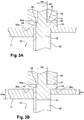
- a longitudinal section is shown along the axis 100 of a wall 11 of a container 1, said wall being pierced with an orifice 12 of section s 12 .
- This orifice makes it possible to fill the container 1.
- the orifice accommodates a plug 20 comprising a tube 30 extending along a longitudinal axis 100, of external nominal section s 30ext and of internal nominal section s 30int .
- "External nominal section” means the average cross-section of the tube, defined by the outer contour of the tube, seen in a transverse section passing through a plane perpendicular to the longitudinal axis 100.
- "Internal nominal section” means the middle section of the tube, defined by the inner contour of the tube, seen in a transverse section passing through a plane perpendicular to the longitudinal axis 100.
- the tube is provided at one end with a collar 33 whose underside 34b is adapted to cover the orifice and whose upper face 34a is adapted to receive a nose 50 riveter.
- the term "adapted to cover the orifice” means that the underside 34b of the flange is largely in abutment against the outer surface of the wall of the container. We hear by "Adapted to receive a riveting nose", the fact that the outer face 34a of the flange can cooperate in frontal contact with a nose riveter.
- the plug positioned in the orifice before having implemented the method to seal the container.
- the cross section of the orifice 12 is greater than the external nominal section s 30ext of the tube 30 so as to voluntarily define a space or clearance m between the wall of the orifice 12 and the outer wall of the tube 30.
- the plug comprises a nail 40 consisting of a rod 41 terminating at one of its ends by a head 42.
- the nail is housed in the tube, so that the head of the nail is located at the end of the tube opposite to the collar and so that the rod extends outside the tube on the side of the flange.
- the head of the nail can extend totally or at least partially outside the tube.
- the nail head can be housed inside the tube.
- the section 42 of the head is smaller than the external nominal section s 30ext of the tube, so as to allow the progression of the head inside the tube.
- the section 42 of the head is greater than the nominal inner section 30int of the tube, so that the progression of the head within the tube causes it to expand.
- the section s 41 of the rod is smaller than the nominal internal section of the tube.
- FIG 2 On the figure 2 is shown in longitudinal section the wall of the container of the figure 1 and its plug always positioned in the orifice, but after having implemented the shutter process.
- the head 42 of the nail has progressed inside the tube until it reaches a position at the orifice 12 and so as to cause the expansion of the tube.
- the clearance m defined between the wall of the orifice and the outer peripheral surface 13 of the plug, is therefore filled.
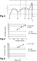
- the figure 4 represents a curve of efforts T applied to the rod during the various steps of the method.
- the path from the position E1 to the position E2 corresponds to the insertion of the nail head into the tube, ie the insertion of the nail head within the nominal section of the tube s30 int .
- the path from the position E2 to the position E4 corresponds to the progression of the nail head in the tube with a peak at E3 corresponding to the maximum force of insertion of the nail head into the thickness of the wall 11.
- E4 the head of the nail comes into abutment against the nose of the riveter and the force increases until the break of the rod in E5.
- the nose 50 of the riveter maintains the flange against the outer wall of the tube container 30.
- the face 51 of the nose 50 of the riveter and the outer face 34a of the flange 33 are flat, so that the contacting of the two faces is easy.
- the face 51 of the nose 50 of the riveter comprises a projecting portion 55 of complementary shape in the form of a recess 35 formed in the flange 33.
- the displacements along an axis perpendicular to the longitudinal axis 100, of the nose of the riveter in relation to the collar are locked.
- This complementarity of shape not only allows easy contact of the two faces but also the maintenance of said contact and the non-exceeding of the rod 41 after its rupture relative to the face 34a, thus protecting the plug from possible shocks.
- the pull of the riveter on the rod firstly causes the entry of the nail head into the tube portion corresponding to the internal nominal section s30 int . Then, the progression of the nail head inside the tube causes the tube to expand against the wall of the orifice. As a result, the space or clearance m between the wall of the orifice 12 and the outer wall of the tube 30 disappears.
- expansion is meant the operation of expanding the tube by plastic deformation.
- the outer diameter of the tube increases as the inner diameter while the thickness of said tube decreases.
- the progression of the head 42 of the nail in the tube ends when said head is at the level of the wall of the container.
- the head of the nail maintains the seal at the contact between the wall of the orifice and the tube and closes the inside of the tube so as to prevent any communication between the inside of the container and the outside.
- the progression of the nail head 42 is completed when the nail head comes into abutment against the nose of the riveter. More specifically, the s section 42 of the nail head is greater than the section s 41 of the rod so as to form a shoulder 44 against which abuts a portion 54 of the nose of the riveter. Likewise, the section 50 of the nose of the riveter is smaller than the section s 42 of the nail head.
- the material constituting the rod 41 has a hardness greater than or equal to three times the hardness of the material constituting the tube 30 and the material constituting the wall of the container has a hardness greater than or equal to 1.3 times that of the tube
- the table below lists a number of possible alloys for the tube and container: Brinell HB hardness Aluminum wall 1100-H14 32 Aluminum tube 1100-O 23 steel nail 165 Aluminum nail 7075 T651 T62 160 stainless steel nail 80
- the gap m between the wall of the orifice 12 and the outer wall of the tube 30 prior to expansion is preferably greater than 0.025 mm.
- the radius clamping should preferably be between 0.05 mm and 0.4 mm.
- the diameter range of the orifice that can be used is between 3.25 and 3.7 mm, ie + 1.5% to + 15% relative to the outside diameter of the tube. tube.
- the rod will admit a diameter of 1.8 mm and the head of the nail, a diameter of 2.4 mm.
- the coefficients 7 and 0.9 have been established empirically by means of tensile tests, taking into account the friction between the nail head and the tube, the latter being similar to the friction between the steel and the steel. aluminum.
- the speed applied to the traction machine was 10 mm / min.
- the breaking strength of the tube is considered by assuming that the law of evolution of the stress following the deformation of the tube in the plastic domain is a constant equal to the rupture limit.
- a coefficient of at least 1.2 can be added to the estimate of the breaking force required in order to overcome a variation of the mechanical characteristics of the parts by 20%.
- the evolution of the insertion force of the nail head has been represented as a function of the tightness at the radius S.
- the tests were carried out at a tensile speed of 10 mm / min on a grade 1100 aluminum tube. in the annealed state, the rod being made of steel and the container being of aluminum with a thickness of 1.8 mm and an orifice of diameter equal to 3.4 mm.
- the diameter of the nail head is the variable, which made it possible to modify the tightening value.
- the figure 5 shows the linearity between the clamping S and the insertion force of the head of the nail, the ordinate at the origin corresponding to the empty insertion force.
- the figure 6 shows the evolution of the insertion force of the nail head according to the thickness e of the container. The tests were carried out with a grade 1100 aluminum tube in the annealed state and with a tightening of 0.19 mm. The figure 6 shows the linearity between the thickness of the cover and the insertion force of the nail head, the ordinate at the origin corresponding to the vacuum insertion force.
- the figure 7 shows the evolution of the insertion force depending on the fracture resistance of R m30 tube.
- the tests were carried out with a lid thickness of 1.8 mm and a tightening of 0.19 mm.
- Two tubes were tested, one of grade 1100 aluminum in the annealed state with an estimated ultimate tensile strength of 100 MPa and the other of grade 5056 aluminum in the annealed state with an estimated ultimate tensile strength. at 290 MPa.
- the figure 7 shows a low intercept in the case of an approximation by a linear curve, which corresponds to the empirically established relationship between the cap and the container.
- the figure 8 shows the evolution of the vacuum expansion force according to the thickness of the tube. Tests were carried out on three grade aluminum tubes 1100 in the annealed state and expanded without clamping force, these tubes having different tube and stem diameters. Samples 1 2 3 ⁇ tube 3.2mm 4 4.8mm ⁇ stem 1.8mm 2.1 2.65mm Section between ⁇ tube and ⁇ stem 5.5mm 2 9.1mm 2 12.6mm 2
- the figure 8 shows the linearity between the thickness of the tube and the vacuum expansion force.
- the method comprises an additional step of breaking the rod 41 of the plug 20, after at least positioning the nose 51 of the riveter against the upper face 34a of the collar 33 of the plug 20.
- the breaking force of the rod is greater than the force resulting from the entry and progression of the head 42 of the nail in the tube.
- the invention is advantageously used in the context of accumulators of the type for example Lithium-Ion.
- the material constituting the container is for example a conventional grade of aluminum and the wall of the container to be sealed is a lid with an electrolyte filling port. This filling orifice is then sealed off against liquids and gases.
- the cover has a thickness e between e min equal to 1 and e max equal to 3 mm and preferably a thickness e between e min equal to 1.8 and e max equal to 2.5 mm.
- the cross sections respectively of the tube 30, the rod 41, the head 42 of the nail 40 and the orifice 12 are elliptical.
- the cross sections respectively of the tube 30, the rod 41, the head 42 of the nail 40 and the orifice 12 are circular.
- the diameter of the orifice 12 is between 3.25 mm and 3.7 mm.
- the tube 30 is preferably "1000 series” aluminum alloy.
- 1000 series aluminum alloy means annealed aluminum shades that do not contain any additive elements. They are distinguished by the presence of more or less impurities. Usually, the third digit indicates the degree of purity by giving the value of the first decimal place to be added to 99% (example: alloy 1050 contains 99.5% aluminum).
- the rod 41 to admit a hardness greater than that of the tube, it is then preferably steel.
- the rod could be made of any material having a tensile strength of between 600 and 1000 MPa.
- the tube 30 is advantageously closed at its end opposite to the flange 33 by a cover 32.
- Other alternatives may also be envisaged such as for example those which consists in coating the nail head with an electrochemically compatible film with the electrolyte.
- the head 42 of the nail 40 extends along a length between 80% and 150% of the sum of the thickness of the wall of the container 1 and the thickness of the flange 33. In this way, the plating of the tube against the wall of the orifice along the longitudinal axis 100 is sufficiently ensured.
- Tightness tests were carried out on 30 aluminum alloy container lids, lids with a thickness of 1.8 mm and the remaining 10 with a thickness of 2.5 mm.
- the same plugs were used, the latter having a 1000 series aluminum tube in order to ensure sufficient compatibility with the electrolyte at the operating potential of the positive electrode of the accumulator, and deformation during expansion.
- the electrolyte is a non-aqueous liquid electrolyte comprising a lithium salt dissolved in a solvent.
- the lithium salt is chosen from LiClO 4 lithium perchlorate, LiPF 6 lithium hexafluorophosphate, LiBF 4 lithium tetrafluoroborate and lithium trifluoromethanesulfonate LiCF 3 SO 3 , lithium bis (fluorosulfonyl) imide Li (FSO 2 ) 2 N (LiFSI), lithium trifluoromethanesulfonimide LiN (CF 3 SO 2 ) 2 (LiTFSI), lithium trifluoromethanesulfonemethide LiC (CF 3 SO 2 ) 3 (LiTFSM), lithium bisperfluoroethylsulfonimide LiN (C 2 F 5 SO 2 ) 2 (LiBETI), lithium 4,5-dicyano-2- (trifluoromethyl) imidazolide (LiTDI), bis (oxalatoborate) ) lithium (LiBOB), lithium tris (pentafluoroethyl) trifluorophosphate
- the solvent is a solvent or a mixture of solvents chosen from common organic solvents, in particular saturated cyclic carbonates, unsaturated cyclic carbonates, non-cyclic carbonates, alkyl esters, such as formates, acetates and propionates. or butyrates, ethers, lactones such as gamma-butyrolactone, tetrahydrothiofene dioxide, nitrile solvents, and mixtures thereof.
- saturated cyclic carbonates include ethylene carbonate (EC), fluoroethylene carbonate (FEC), propylene carbonate (PC), butylene carbonate (BC), and mixtures thereof. this.
- Unsaturated cyclic carbonates include, for example, vinylene carbonate (VC), its derivatives and mixtures thereof.
- Non-cyclic carbonates include, for example, dimethyl carbonate (DMC), diethyl carbonate (DEC), methyl ethyl carbonate (EMC), dipropyl carbonate (DPC) and mixtures thereof.
- DMC dimethyl carbonate
- DEC diethyl carbonate
- EMC methyl ethyl carbonate
- DPC dipropyl carbonate
- alkyl esters mention may be made, for example, of methyl acetate, ethyl acetate, methyl propionate, ethyl propionate, butyl propionate, methyl butyrate, butyrate and the like. ethyl, propyl butyrate and mixtures thereof.
- ethers there may be mentioned, for example, dimethyl ether (DME) or diethyl ether (DEE), and mixtures thereof.
- the nail was chosen from steel to ensure a comfortable margin of effort so that the breakage of the rod only intervenes in abutment against the nose of the riveter and not before.
- a standard pneumatic riveter was used. Of course, other types of riveters could also be suitable.
- the helium leakage rate was found to be less than 1.10 -7 atm.cm 3 / s.
- Sample N ° Helium leak rate (atm.cm3 / s) Sample 1 2,4E-08 Sample 2 2.8E-08 Sample 3 2.8E-08 Sample 4 3,1E-08 Sample 5 3.5E-08 Sample 6 7,0E-08 Sample 7 8,5E-08 Sample 8 8,7E-08 Sample 9 2.5E-08 Sample 10 3.7E-08
- the invention makes it possible to reliably seal the filling orifices of the containers.
- the method according to the invention is advantageously simplified by the fact that it requires only a single piece, a plug consisting of a nail housed in a tube. It is indeed not necessary to add washers and other seal. Seals are understood to mean any addition of elements ensuring the sealing function.
- the method according to the invention also has the advantage of being able to be used on particularly small container wall thicknesses, which may be of the order of 1 mm.
Landscapes
- Chemical & Material Sciences (AREA)
- Chemical Kinetics & Catalysis (AREA)
- Electrochemistry (AREA)
- General Chemical & Material Sciences (AREA)
- Sealing Battery Cases Or Jackets (AREA)
- Filling Or Discharging Of Gas Storage Vessels (AREA)
- Filling, Topping-Up Batteries (AREA)
Claims (20)
- Verfahren, um eine Einfüllöffnung (12), die an einer Wand (11) eines Akkumulatorbehälters (1) angeordnet ist, mittels eines Stopfens (20) abzuddichten, wobei der Stopfen Folgendes umfasst:- ein Rohr (30), wobei das Rohr an einem seiner Enden mit einem Flansch (33) versehen ist, der eine Oberseite aufweist (34a), die geeignet ist, eine Nase (50) einer Nietmaschine aufzunehmen, und eine Unterseite (34b), die zum Abdecken der Öffnung dienen kann, und- einen Nagel (40), der mit einem Schaft (41) versehen ist, welcher mit einem Kopf (42) endet, wobei der Schaft in dem Rohr untergebracht und der Kopf an einem Ende des Nagels dem Flansch (33) gegenüberliegend angeordnet ist, wobei der Kopf des Nagels einen Querschnitt hat, der zwischen dem Innenquerschnitt (s30int) und dem Außenquerschnitt (s30ext) des Rohrs (30) liegt, wobei das Material, aus dem das Rohr (41) besteht, eine Härte zulässt, die größer oder gleich dreimal die Härte des Materials aus dem das Rohr (30) besteht zulässt,wobei das Verfahren die folgenden Schritte umfasst die darin bestehen:- den Stopfen (20) in die Öffnung (12) einzuführen, wobei der Querschnitt der Öffnung (12) größer als der Außenquerschnitt (s30ext) des Rohrs (30) ist, um somit absichtlich einen Raum (m) zwischen der Wand der Öffnung (12) und der Außenwand des Rohrs (30) zu definieren,- die Nase (50) der Nietmaschine an der Oberseite (34a) des Flansches (33) des Stopfens (20) in Anschlag anzuordnen,- die Nietmaschine zu betätigen, um einen Zug auf den Schaft (41) des Nagels (40) auszuüben, wobei die Nase (50) der Nietmaschine das Rohr (30) innerhalb der Öffnung (12) hält,wobei das Verfahren dadurch gekennzeichnet ist, dass die Nietmaschine betätigt wird, um:• die Rohrerweiterung (30) gegen die Wand der Öffnung (12) durch das Eintreten und das Fortschreiten des Nagelkopfs (42) in dem Rohr hervorzurufen, und• den Raum (m) zwischen der Wand der Öffnung (12) und der Außenwand des Rohrs (30) durch das Fortschreiten und Halten des Nagelkopfs (42) im Rohr auf Höhe der Wand des Akkumulatorbehälters auszufüllen;wobei das Material, aus dem die Wand des Akkumulatorbehälters besteht, eine Härte größer oder gleich 1,3-mal jener des Rohrs (30) zulässt.
- Verfahren für die Abdichtung einer Einfüllöffnung nach dem vorhergehenden Anspruch, dadurch gekennzeichnet, dass es einen zusätzlichen Schritt umfasst, der darin besteht, den Schaft (41) des Stopfens (20) zu brechen, nachdem zumindest die Nase (50) einer Nietmaschine an die Oberseite (34a) des Flansches (33) des Stopfens (20) in Anschlag angeordnet worden ist, wobei die Kraft zum Brechen des Schafts größer als die Kraft ist, die sich aus dem Eintreten und Fortschreiten des Nagelkopfs (42) in dem Rohr ergibt, und wobei der Querschnitt (s50) der Nietmaschine kleiner als der Querschnitt (s42) des Nagelkopfs (42) ist.
- Verfahren für die Abdichtung einer Einfüllöffnung nach einem der vorhergehenden Ansprüche, dadurch gekennzeichnet, dass der Raum m vor der Rohrerweiterung (30) der Differenz zwischen dem Durchmesser der Öffnung und dem Außendurchmesser des Rohrs entspricht, wobei diese größer als 0,05 mm ist.
- Verfahren für die Abdichtung einer Einfüllöffnung nach einem der vorhergehenden Ansprüche, dadurch gekennzeichnet, dass der Schaft einen Schwächungsbereich (43) mit einem kleineren Querschnitt als der durchschnittliche Querschnitt der Stange aufweist, so dass der Bruch des Schafts (41) im Bereich des Schwächungsbereichs (34), bei Zugkräften unter Rm41*s41' stattfindet.
Wobei:- s41': der Querschnitt des Schafts nach Zugbruch ist- Rm41 : die mechanische Zugfestigkeit des Schafts ist - Verfahren für die Abdichtung einer Einfüllöffnung nach einem der vorhergehenden Ansprüche, dadurch gekennzeichnet, dass der Schaft (41) aus Stahl ist.
- Verfahren für die Abdichtung einer Einfüllöffnung nach einem der vorhergehenden Ansprüche, dadurch gekennzeichnet, dass das Rohr (30) aus Aluminiumlegierung, vorzugsweise aus Aluminiumlegierung "Serie 1000" ist.
- Verfahren für die Abdichtung einer Einfüllöffnung nach einem der vorhergehenden Ansprüche, dadurch gekennzeichnet, dass das Rohr (30) an seinem, dem Flansch (33) gegenüberliegenden Ende durch einen Deckel (32) verschlossen ist.
- Verfahren für die Abdichtung einer Einfüllöffnung nach einem der vorhergehenden Ansprüche, dadurch gekennzeichnet, dass der Kopf (42) des Nagels (40) sich über eine Länge erstreckt, die zwischen 80 % und 150 % der Summe der Dicke der Wand des Akkumulatorbehälters (1) und der Dicke des Flansches (33) liegt.
- Verfahren für die Abdichtung einer Einfüllöffnung nach einem der vorhergehenden Ansprüche, dadurch gekennzeichnet, dass die Fläche (51) der Nase (50) der Nietmaschine und die Oberfläche (34) des Flansches (33) des Stopfens (20) eben sind.
- Verfahren für die Abdichtung einer Einfüllöffnung nach einem der vorhergehenden Ansprüche, dadurch gekennzeichnet, dass die Fläche (51) der Nase (50) der Nietmaschine einen komplementar geformten Vorsprung (55) einer Ausnehmung (35) umfasst, die auf der Oberseite (34a) des Flansches (33) des Stopfens (20) vorgesehen ist.
- Verfahren für die Abdichtung einer Einfüllöffnung nach einem der vorhergehenden Ansprüche, dadurch gekennzeichnet, dass die Wand des Akkumulatorbehälters eine Dicke zwischen 1 und 3 mm und vorzugsweise zwischen 1,8 und 2,5 mm zulässt.
- Verfahren für die Abdichtung einer Einfüllöffnung nach einem der vorhergehenden Ansprüche, dadurch gekennzeichnet, dass der Akkumulatorbehälter (1) aus Aluminium ist.
- Verfahren für die Abdichtung einer Einfüllöffnung nach einem der vorhergehenden Ansprüche, dadurch gekennzeichnet, dass die jeweiligen Querschnitte des Rohrs (30), des Schafts (41), des Kopfes (42) des Nagels (40) und der Öffnung (12) elliptisch sind.
- Verfahren für die Abdichtung einer Einfüllöffnung nach einem der vorhergehenden Ansprüche, dadurch gekennzeichnet, dass die jeweiligen Querschnitte des Rohrs (30), des Schafts (41), des Kopfes (42) des Nagels (40) und der Öffnung (12) kreisförmig sind.
- Verfahren für die Abdichtung einer Einfüllöffnung nach einem der vorhergehenden Ansprüche, dadurch gekennzeichnet, dass der Durchmesser der Öffnung (12) zwischen 3,25 und 3,7 mm beträgt.
- Verfahren für die Abdichtung einer Einfüllöffnung nach einem der vorhergehenden Ansprüche, dadurch gekennzeichnet, dass die Wand des Akkumulatorbehälters (1) ein Akkumulatorbehälterdeckel ist, wobei die Einfüllöffnung (12) eine Öffnung zur Elektrolytfüllung ist.
- Verfahren für die Abdichtung einer Einfüllöffnung nach einem der vorhergehenden Ansprüche, dadurch gekennzeichnet, dass der Akkumulator ein Lithium-Ionen-Akkumulator ist.
- Verfahren für die Abdichtung einer Einfüllöffnung nach einem der vorhergehenden Ansprüche, dadurch gekennzeichnet, dass der Stopfen (20) und der Akkumulatorbehälter (1) die folgenden Verhältnisse erfüllen:- s41 < s30int < s42 < s30ext < s12- s42 - s41 > s12 - s30ext- Rm41 * s41' > 7 * Rm30 * e * (s42 - s41+s30ext - s12)/2 + 0.9 Rm30 * (s30ext - S41).Wobei:- s41, s41', s30int, s42, s30ext, S12 jeweils die Querschnitte des Schafts vor und nach dem Zugbruch, des (inneren) Rohrs, des Nagelkopfs, des (äußeren) Rohrs, der Öffnung sind,- e: die Dicke des Akkumulatorbehälters ist,- Rm30 und Rm41 : die mechanische Zugfestigkeit des Schafts sind.
- Verfahren für die Abdichtung einer Einfüllöffnung nach einem der vorhergehenden Ansprüche, dadurch gekennzeichnet, dass der Stopfen ausschließlich von dem Rohr und dem Nagel gebildet ist.
- Akkumulatorbehälter (1), der mit einer Öffnung zur Elektrolytfüllung versehen ist, dadurch gekennzeichnet, dass die Einfüllöffnung mittels eines Verfahrens nach einem der Ansprüche 1 bis 19 gegen Flüssigkeiten und Gase abgedichtet ist.
Applications Claiming Priority (1)
| Application Number | Priority Date | Filing Date | Title |
|---|---|---|---|
| FR1461017A FR3028673B1 (fr) | 2014-11-14 | 2014-11-14 | Procede pour rendre etanche un orifice de conteneur d'accumulateur et conteneur rendu etanche par ledit procede. |
Publications (2)
| Publication Number | Publication Date |
|---|---|
| EP3021383A1 EP3021383A1 (de) | 2016-05-18 |
| EP3021383B1 true EP3021383B1 (de) | 2017-05-17 |
Family
ID=52627327
Family Applications (1)
| Application Number | Title | Priority Date | Filing Date |
|---|---|---|---|
| EP15193073.2A Active EP3021383B1 (de) | 2014-11-14 | 2015-11-04 | Verfahren zum wasserdichten abdichten einer öffnung eines akkumulatorgehäuses, und durch dieses verfahren abgedichtetes gehäuse |
Country Status (3)
| Country | Link |
|---|---|
| US (1) | US9972825B2 (de) |
| EP (1) | EP3021383B1 (de) |
| FR (1) | FR3028673B1 (de) |
Families Citing this family (4)
| Publication number | Priority date | Publication date | Assignee | Title |
|---|---|---|---|---|
| JP6722399B2 (ja) * | 2016-05-23 | 2020-07-15 | 株式会社Gsユアサ | 蓄電素子、及び蓄電素子の製造方法 |
| CN111014559B (zh) * | 2019-11-11 | 2022-01-07 | 大族激光科技产业集团股份有限公司 | 电池模组的上盖夹具 |
| CN114211221B (zh) * | 2022-02-22 | 2022-06-21 | 深圳市誉辰智能装备股份有限公司 | 打钉装置 |
| CN114976259B (zh) * | 2022-05-19 | 2025-11-18 | 苏州领略智能科技有限公司 | 锂电池盖铆压组装机构 |
Family Cites Families (11)
| Publication number | Priority date | Publication date | Assignee | Title |
|---|---|---|---|---|
| DE1056335B (de) | 1955-07-01 | 1959-04-30 | Eastman Kodak Co | Optisches Glas |
| FR2329080A1 (fr) | 1975-10-22 | 1977-05-20 | Accumulateurs Fixes | Traversee etanche du couvercle d'un accumulateur par une borne en plomb |
| US4215187A (en) | 1977-09-23 | 1980-07-29 | Varta Batterie Aktiengesellschaft | Gas-tight galvanic cell |
| JP2897104B2 (ja) | 1994-06-03 | 1999-05-31 | 古河電池株式会社 | 密閉型アルカリ蓄電池の製造方法 |
| JP5400711B2 (ja) * | 2010-06-25 | 2014-01-29 | 日立ビークルエナジー株式会社 | 封止具及び密閉式電池 |
| CN102299273A (zh) | 2010-06-28 | 2011-12-28 | 黎永康 | 动力锂电池顶盖电极柱密封连接和防爆装置及其制造方法 |
| FR2972442B1 (fr) | 2011-03-08 | 2013-03-29 | Accumulateurs Fixes | Materiau d'electrode positive pour accumulateur lithium-ion |
| CN103814457B (zh) * | 2011-09-27 | 2016-08-17 | 丰田自动车株式会社 | 电池 |
| JP5998912B2 (ja) * | 2012-12-18 | 2016-09-28 | 株式会社豊田自動織機 | 蓄電装置 |
| US20140186133A1 (en) * | 2012-12-27 | 2014-07-03 | Richard Bergner Verbindungstechnik Gmbh & Co. Kg | Joint connection between two components, rivet sleeve and blind rivet for such a joint connection and method for producing such a joint connection |
| JP6086210B2 (ja) * | 2012-12-28 | 2017-03-01 | 株式会社Gsユアサ | 蓄電素子の製造方法 |
-
2014
- 2014-11-14 FR FR1461017A patent/FR3028673B1/fr active Active
-
2015
- 2015-11-04 EP EP15193073.2A patent/EP3021383B1/de active Active
- 2015-11-11 US US14/938,452 patent/US9972825B2/en active Active
Also Published As
| Publication number | Publication date |
|---|---|
| EP3021383A1 (de) | 2016-05-18 |
| US9972825B2 (en) | 2018-05-15 |
| FR3028673B1 (fr) | 2016-11-25 |
| US20160141595A1 (en) | 2016-05-19 |
| FR3028673A1 (fr) | 2016-05-20 |
Similar Documents
| Publication | Publication Date | Title |
|---|---|---|
| EP2984697B1 (de) | Elektrochemische lithiumspeicherbatterie mit einem gehäuse mit verbesserter wärmeableitung, batteriepack und zugehöriges herstellungsverfahren | |
| EP1626456B1 (de) | Sicherheitseinrichtung für einen gasdicht verschlossenen Akkumulator | |
| EP3329539B1 (de) | Lithiumspeicherbatterie mit integriertem schutzschalter für verbesserte bediensicherheit | |
| EP2329546B1 (de) | Batterie mit flüssigelektrolyt und füllverfahren dafür | |
| EP3329527B1 (de) | Lithiumspeicherbatterie mit integriertem schutzschalter für verbesserte bediensicherheit | |
| EP3130020B1 (de) | Elektrochemischer lithium-ionen-akku mit direkt an die elektrodenanordnung angeschlossenem anschluss und zugehöriges herstellungsverfahren | |
| EP3021383B1 (de) | Verfahren zum wasserdichten abdichten einer öffnung eines akkumulatorgehäuses, und durch dieses verfahren abgedichtetes gehäuse | |
| EP3029754B1 (de) | Abgedichtete batterie und verfahren zur herstellung | |
| EP3410514B1 (de) | Poldurchführung als anschlussklemme mit gasauslassventil für einen elektrochemischen metall-ionen-akku, sowie entsprechender akku | |
| EP2828906B1 (de) | Energiespeicheranordnung mit einem elektrisch isolierenden elastischen ring | |
| EP1930113B1 (de) | Schweißverfahren durch einem Laser mit einer optischen Ringvorrichtung | |
| EP2962340B1 (de) | Sicherheitsvorrichtung für eine batterie von elektrochemischen lithiumgeneratoren | |
| FR2601819A1 (fr) | Pile electrochimique et son procede de fabrication | |
| EP3488454B1 (de) | Prozess zur herststellung von hybrid zylinderförmiges superkondensator mit alkalimetalionen | |
| EP3510652B1 (de) | Durchführung zur bildung einer klemme für eine elektrochemische metall-ionen-batterie und entsprechende batterie | |
| FR2908740A1 (fr) | Dispositif de securite pour accumulateur etanche | |
| EP4187667A2 (de) | Verfahren zur herstellung einer festkörperbatterie aus einem elektrochemischen flüssigelektrolyt-metall-ionen-akkumulator für thermische abuse tests | |
| EP4468438A1 (de) | Verfahren zur herstellung einer lithium-metall- oder natrium-metall-festkörperbatterie aus einem elektrochemischen flüssigelektrolyt-akkumulator zur thermischen unschädlichmachung | |
| FR3016736A1 (fr) | Batterie lithium-ion (li-ion) a capacite augmentee par augmentation de la hauteur disponible a l'interieur du boitier |
Legal Events
| Date | Code | Title | Description |
|---|---|---|---|
| PUAI | Public reference made under article 153(3) epc to a published international application that has entered the european phase |
Free format text: ORIGINAL CODE: 0009012 |
|
| AK | Designated contracting states |
Kind code of ref document: A1 Designated state(s): AL AT BE BG CH CY CZ DE DK EE ES FI FR GB GR HR HU IE IS IT LI LT LU LV MC MK MT NL NO PL PT RO RS SE SI SK SM TR |
|
| AX | Request for extension of the european patent |
Extension state: BA ME |
|
| 17P | Request for examination filed |
Effective date: 20161019 |
|
| RBV | Designated contracting states (corrected) |
Designated state(s): AL AT BE BG CH CY CZ DE DK EE ES FI FR GB GR HR HU IE IS IT LI LT LU LV MC MK MT NL NO PL PT RO RS SE SI SK SM TR |
|
| GRAP | Despatch of communication of intention to grant a patent |
Free format text: ORIGINAL CODE: EPIDOSNIGR1 |
|
| RIC1 | Information provided on ipc code assigned before grant |
Ipc: H01M 10/0525 20100101ALN20161107BHEP Ipc: H01M 2/36 20060101AFI20161107BHEP Ipc: F16B 19/00 20060101ALN20161107BHEP Ipc: B21J 15/00 20060101ALN20161107BHEP |
|
| RIC1 | Information provided on ipc code assigned before grant |
Ipc: B21J 15/00 20060101ALN20161111BHEP Ipc: H01M 2/36 20060101AFI20161111BHEP Ipc: F16B 19/00 20060101ALN20161111BHEP Ipc: H01M 10/0525 20100101ALN20161111BHEP |
|
| INTG | Intention to grant announced |
Effective date: 20161215 |
|
| GRAS | Grant fee paid |
Free format text: ORIGINAL CODE: EPIDOSNIGR3 |
|
| GRAA | (expected) grant |
Free format text: ORIGINAL CODE: 0009210 |
|
| AK | Designated contracting states |
Kind code of ref document: B1 Designated state(s): AL AT BE BG CH CY CZ DE DK EE ES FI FR GB GR HR HU IE IS IT LI LT LU LV MC MK MT NL NO PL PT RO RS SE SI SK SM TR |
|
| REG | Reference to a national code |
Ref country code: GB Ref legal event code: FG4D Free format text: NOT ENGLISH |
|
| REG | Reference to a national code |
Ref country code: CH Ref legal event code: EP |
|
| REG | Reference to a national code |
Ref country code: IE Ref legal event code: FG4D Free format text: LANGUAGE OF EP DOCUMENT: FRENCH |
|
| REG | Reference to a national code |
Ref country code: AT Ref legal event code: REF Ref document number: 895196 Country of ref document: AT Kind code of ref document: T Effective date: 20170615 |
|
| REG | Reference to a national code |
Ref country code: DE Ref legal event code: R096 Ref document number: 602015002765 Country of ref document: DE |
|
| REG | Reference to a national code |
Ref country code: NL Ref legal event code: MP Effective date: 20170517 |
|
| REG | Reference to a national code |
Ref country code: LT Ref legal event code: MG4D |
|
| REG | Reference to a national code |
Ref country code: AT Ref legal event code: MK05 Ref document number: 895196 Country of ref document: AT Kind code of ref document: T Effective date: 20170517 |
|
| PG25 | Lapsed in a contracting state [announced via postgrant information from national office to epo] |
Ref country code: ES Free format text: LAPSE BECAUSE OF FAILURE TO SUBMIT A TRANSLATION OF THE DESCRIPTION OR TO PAY THE FEE WITHIN THE PRESCRIBED TIME-LIMIT Effective date: 20170517 Ref country code: HR Free format text: LAPSE BECAUSE OF FAILURE TO SUBMIT A TRANSLATION OF THE DESCRIPTION OR TO PAY THE FEE WITHIN THE PRESCRIBED TIME-LIMIT Effective date: 20170517 Ref country code: LT Free format text: LAPSE BECAUSE OF FAILURE TO SUBMIT A TRANSLATION OF THE DESCRIPTION OR TO PAY THE FEE WITHIN THE PRESCRIBED TIME-LIMIT Effective date: 20170517 Ref country code: NO Free format text: LAPSE BECAUSE OF FAILURE TO SUBMIT A TRANSLATION OF THE DESCRIPTION OR TO PAY THE FEE WITHIN THE PRESCRIBED TIME-LIMIT Effective date: 20170817 Ref country code: AT Free format text: LAPSE BECAUSE OF FAILURE TO SUBMIT A TRANSLATION OF THE DESCRIPTION OR TO PAY THE FEE WITHIN THE PRESCRIBED TIME-LIMIT Effective date: 20170517 Ref country code: FI Free format text: LAPSE BECAUSE OF FAILURE TO SUBMIT A TRANSLATION OF THE DESCRIPTION OR TO PAY THE FEE WITHIN THE PRESCRIBED TIME-LIMIT Effective date: 20170517 Ref country code: GR Free format text: LAPSE BECAUSE OF FAILURE TO SUBMIT A TRANSLATION OF THE DESCRIPTION OR TO PAY THE FEE WITHIN THE PRESCRIBED TIME-LIMIT Effective date: 20170818 |
|
| REG | Reference to a national code |
Ref country code: FR Ref legal event code: PLFP Year of fee payment: 3 |
|
| PG25 | Lapsed in a contracting state [announced via postgrant information from national office to epo] |
Ref country code: PL Free format text: LAPSE BECAUSE OF FAILURE TO SUBMIT A TRANSLATION OF THE DESCRIPTION OR TO PAY THE FEE WITHIN THE PRESCRIBED TIME-LIMIT Effective date: 20170517 Ref country code: LV Free format text: LAPSE BECAUSE OF FAILURE TO SUBMIT A TRANSLATION OF THE DESCRIPTION OR TO PAY THE FEE WITHIN THE PRESCRIBED TIME-LIMIT Effective date: 20170517 Ref country code: SE Free format text: LAPSE BECAUSE OF FAILURE TO SUBMIT A TRANSLATION OF THE DESCRIPTION OR TO PAY THE FEE WITHIN THE PRESCRIBED TIME-LIMIT Effective date: 20170517 Ref country code: RS Free format text: LAPSE BECAUSE OF FAILURE TO SUBMIT A TRANSLATION OF THE DESCRIPTION OR TO PAY THE FEE WITHIN THE PRESCRIBED TIME-LIMIT Effective date: 20170517 Ref country code: IS Free format text: LAPSE BECAUSE OF FAILURE TO SUBMIT A TRANSLATION OF THE DESCRIPTION OR TO PAY THE FEE WITHIN THE PRESCRIBED TIME-LIMIT Effective date: 20170917 Ref country code: NL Free format text: LAPSE BECAUSE OF FAILURE TO SUBMIT A TRANSLATION OF THE DESCRIPTION OR TO PAY THE FEE WITHIN THE PRESCRIBED TIME-LIMIT Effective date: 20170517 Ref country code: BG Free format text: LAPSE BECAUSE OF FAILURE TO SUBMIT A TRANSLATION OF THE DESCRIPTION OR TO PAY THE FEE WITHIN THE PRESCRIBED TIME-LIMIT Effective date: 20170817 |
|
| PG25 | Lapsed in a contracting state [announced via postgrant information from national office to epo] |
Ref country code: RO Free format text: LAPSE BECAUSE OF FAILURE TO SUBMIT A TRANSLATION OF THE DESCRIPTION OR TO PAY THE FEE WITHIN THE PRESCRIBED TIME-LIMIT Effective date: 20170517 Ref country code: DK Free format text: LAPSE BECAUSE OF FAILURE TO SUBMIT A TRANSLATION OF THE DESCRIPTION OR TO PAY THE FEE WITHIN THE PRESCRIBED TIME-LIMIT Effective date: 20170517 Ref country code: CZ Free format text: LAPSE BECAUSE OF FAILURE TO SUBMIT A TRANSLATION OF THE DESCRIPTION OR TO PAY THE FEE WITHIN THE PRESCRIBED TIME-LIMIT Effective date: 20170517 Ref country code: EE Free format text: LAPSE BECAUSE OF FAILURE TO SUBMIT A TRANSLATION OF THE DESCRIPTION OR TO PAY THE FEE WITHIN THE PRESCRIBED TIME-LIMIT Effective date: 20170517 Ref country code: SK Free format text: LAPSE BECAUSE OF FAILURE TO SUBMIT A TRANSLATION OF THE DESCRIPTION OR TO PAY THE FEE WITHIN THE PRESCRIBED TIME-LIMIT Effective date: 20170517 |
|
| REG | Reference to a national code |
Ref country code: DE Ref legal event code: R097 Ref document number: 602015002765 Country of ref document: DE |
|
| PG25 | Lapsed in a contracting state [announced via postgrant information from national office to epo] |
Ref country code: IT Free format text: LAPSE BECAUSE OF FAILURE TO SUBMIT A TRANSLATION OF THE DESCRIPTION OR TO PAY THE FEE WITHIN THE PRESCRIBED TIME-LIMIT Effective date: 20170517 Ref country code: SM Free format text: LAPSE BECAUSE OF FAILURE TO SUBMIT A TRANSLATION OF THE DESCRIPTION OR TO PAY THE FEE WITHIN THE PRESCRIBED TIME-LIMIT Effective date: 20170517 |
|
| PLBE | No opposition filed within time limit |
Free format text: ORIGINAL CODE: 0009261 |
|
| STAA | Information on the status of an ep patent application or granted ep patent |
Free format text: STATUS: NO OPPOSITION FILED WITHIN TIME LIMIT |
|
| 26N | No opposition filed |
Effective date: 20180220 |
|
| PG25 | Lapsed in a contracting state [announced via postgrant information from national office to epo] |
Ref country code: SI Free format text: LAPSE BECAUSE OF FAILURE TO SUBMIT A TRANSLATION OF THE DESCRIPTION OR TO PAY THE FEE WITHIN THE PRESCRIBED TIME-LIMIT Effective date: 20170517 |
|
| PG25 | Lapsed in a contracting state [announced via postgrant information from national office to epo] |
Ref country code: MC Free format text: LAPSE BECAUSE OF FAILURE TO SUBMIT A TRANSLATION OF THE DESCRIPTION OR TO PAY THE FEE WITHIN THE PRESCRIBED TIME-LIMIT Effective date: 20170517 |
|
| PG25 | Lapsed in a contracting state [announced via postgrant information from national office to epo] |
Ref country code: LU Free format text: LAPSE BECAUSE OF NON-PAYMENT OF DUE FEES Effective date: 20171104 |
|
| REG | Reference to a national code |
Ref country code: BE Ref legal event code: MM Effective date: 20171130 |
|
| REG | Reference to a national code |
Ref country code: IE Ref legal event code: MM4A |
|
| PG25 | Lapsed in a contracting state [announced via postgrant information from national office to epo] |
Ref country code: MT Free format text: LAPSE BECAUSE OF FAILURE TO SUBMIT A TRANSLATION OF THE DESCRIPTION OR TO PAY THE FEE WITHIN THE PRESCRIBED TIME-LIMIT Effective date: 20170517 |
|
| PG25 | Lapsed in a contracting state [announced via postgrant information from national office to epo] |
Ref country code: IE Free format text: LAPSE BECAUSE OF NON-PAYMENT OF DUE FEES Effective date: 20171104 |
|
| REG | Reference to a national code |
Ref country code: FR Ref legal event code: PLFP Year of fee payment: 4 |
|
| PG25 | Lapsed in a contracting state [announced via postgrant information from national office to epo] |
Ref country code: BE Free format text: LAPSE BECAUSE OF NON-PAYMENT OF DUE FEES Effective date: 20171130 |
|
| PG25 | Lapsed in a contracting state [announced via postgrant information from national office to epo] |
Ref country code: HU Free format text: LAPSE BECAUSE OF FAILURE TO SUBMIT A TRANSLATION OF THE DESCRIPTION OR TO PAY THE FEE WITHIN THE PRESCRIBED TIME-LIMIT; INVALID AB INITIO Effective date: 20151104 |
|
| REG | Reference to a national code |
Ref country code: CH Ref legal event code: PL |
|
| PG25 | Lapsed in a contracting state [announced via postgrant information from national office to epo] |
Ref country code: LI Free format text: LAPSE BECAUSE OF NON-PAYMENT OF DUE FEES Effective date: 20181130 Ref country code: CH Free format text: LAPSE BECAUSE OF NON-PAYMENT OF DUE FEES Effective date: 20181130 |
|
| PG25 | Lapsed in a contracting state [announced via postgrant information from national office to epo] |
Ref country code: CY Free format text: LAPSE BECAUSE OF FAILURE TO SUBMIT A TRANSLATION OF THE DESCRIPTION OR TO PAY THE FEE WITHIN THE PRESCRIBED TIME-LIMIT Effective date: 20170517 |
|
| PG25 | Lapsed in a contracting state [announced via postgrant information from national office to epo] |
Ref country code: MK Free format text: LAPSE BECAUSE OF FAILURE TO SUBMIT A TRANSLATION OF THE DESCRIPTION OR TO PAY THE FEE WITHIN THE PRESCRIBED TIME-LIMIT Effective date: 20170517 |
|
| PG25 | Lapsed in a contracting state [announced via postgrant information from national office to epo] |
Ref country code: TR Free format text: LAPSE BECAUSE OF FAILURE TO SUBMIT A TRANSLATION OF THE DESCRIPTION OR TO PAY THE FEE WITHIN THE PRESCRIBED TIME-LIMIT Effective date: 20170517 |
|
| PG25 | Lapsed in a contracting state [announced via postgrant information from national office to epo] |
Ref country code: PT Free format text: LAPSE BECAUSE OF FAILURE TO SUBMIT A TRANSLATION OF THE DESCRIPTION OR TO PAY THE FEE WITHIN THE PRESCRIBED TIME-LIMIT Effective date: 20170517 |
|
| PG25 | Lapsed in a contracting state [announced via postgrant information from national office to epo] |
Ref country code: AL Free format text: LAPSE BECAUSE OF FAILURE TO SUBMIT A TRANSLATION OF THE DESCRIPTION OR TO PAY THE FEE WITHIN THE PRESCRIBED TIME-LIMIT Effective date: 20170517 |
|
| REG | Reference to a national code |
Ref country code: DE Ref legal event code: R079 Ref document number: 602015002765 Country of ref document: DE Free format text: PREVIOUS MAIN CLASS: H01M0002360000 Ipc: H01M0050600000 |
|
| P01 | Opt-out of the competence of the unified patent court (upc) registered |
Effective date: 20230514 |
|
| PGFP | Annual fee paid to national office [announced via postgrant information from national office to epo] |
Ref country code: GB Payment date: 20241128 Year of fee payment: 10 |
|
| PGFP | Annual fee paid to national office [announced via postgrant information from national office to epo] |
Ref country code: DE Payment date: 20251127 Year of fee payment: 11 |
|
| PGFP | Annual fee paid to national office [announced via postgrant information from national office to epo] |
Ref country code: FR Payment date: 20251128 Year of fee payment: 11 |