EP2329546B1 - Batterie mit flüssigelektrolyt und füllverfahren dafür - Google Patents
Batterie mit flüssigelektrolyt und füllverfahren dafür Download PDFInfo
- Publication number
- EP2329546B1 EP2329546B1 EP09817277A EP09817277A EP2329546B1 EP 2329546 B1 EP2329546 B1 EP 2329546B1 EP 09817277 A EP09817277 A EP 09817277A EP 09817277 A EP09817277 A EP 09817277A EP 2329546 B1 EP2329546 B1 EP 2329546B1
- Authority
- EP
- European Patent Office
- Prior art keywords
- liquid electrolyte
- electrolyte solution
- cavity
- lateral hole
- housing
- Prior art date
- Legal status (The legal status is an assumption and is not a legal conclusion. Google has not performed a legal analysis and makes no representation as to the accuracy of the status listed.)
- Not-in-force
Links
Images


Classifications
-
- H—ELECTRICITY
- H01—ELECTRIC ELEMENTS
- H01M—PROCESSES OR MEANS, e.g. BATTERIES, FOR THE DIRECT CONVERSION OF CHEMICAL ENERGY INTO ELECTRICAL ENERGY
- H01M10/00—Secondary cells; Manufacture thereof
- H01M10/05—Accumulators with non-aqueous electrolyte
- H01M10/052—Li-accumulators
-
- H—ELECTRICITY
- H01—ELECTRIC ELEMENTS
- H01M—PROCESSES OR MEANS, e.g. BATTERIES, FOR THE DIRECT CONVERSION OF CHEMICAL ENERGY INTO ELECTRICAL ENERGY
- H01M50/00—Constructional details or processes of manufacture of the non-active parts of electrochemical cells other than fuel cells, e.g. hybrid cells
- H01M50/10—Primary casings; Jackets or wrappings
- H01M50/102—Primary casings; Jackets or wrappings characterised by their shape or physical structure
- H01M50/103—Primary casings; Jackets or wrappings characterised by their shape or physical structure prismatic or rectangular
-
- H—ELECTRICITY
- H01—ELECTRIC ELEMENTS
- H01M—PROCESSES OR MEANS, e.g. BATTERIES, FOR THE DIRECT CONVERSION OF CHEMICAL ENERGY INTO ELECTRICAL ENERGY
- H01M50/00—Constructional details or processes of manufacture of the non-active parts of electrochemical cells other than fuel cells, e.g. hybrid cells
- H01M50/10—Primary casings; Jackets or wrappings
- H01M50/147—Lids or covers
-
- H—ELECTRICITY
- H01—ELECTRIC ELEMENTS
- H01M—PROCESSES OR MEANS, e.g. BATTERIES, FOR THE DIRECT CONVERSION OF CHEMICAL ENERGY INTO ELECTRICAL ENERGY
- H01M50/00—Constructional details or processes of manufacture of the non-active parts of electrochemical cells other than fuel cells, e.g. hybrid cells
- H01M50/60—Arrangements or processes for filling or topping-up with liquids; Arrangements or processes for draining liquids from casings
- H01M50/609—Arrangements or processes for filling with liquid, e.g. electrolytes
- H01M50/627—Filling ports
- H01M50/636—Closing or sealing filling ports, e.g. using lids
- H01M50/645—Plugs
-
- H—ELECTRICITY
- H01—ELECTRIC ELEMENTS
- H01M—PROCESSES OR MEANS, e.g. BATTERIES, FOR THE DIRECT CONVERSION OF CHEMICAL ENERGY INTO ELECTRICAL ENERGY
- H01M2300/00—Electrolytes
- H01M2300/0017—Non-aqueous electrolytes
- H01M2300/002—Inorganic electrolyte
- H01M2300/0022—Room temperature molten salts
-
- Y—GENERAL TAGGING OF NEW TECHNOLOGICAL DEVELOPMENTS; GENERAL TAGGING OF CROSS-SECTIONAL TECHNOLOGIES SPANNING OVER SEVERAL SECTIONS OF THE IPC; TECHNICAL SUBJECTS COVERED BY FORMER USPC CROSS-REFERENCE ART COLLECTIONS [XRACs] AND DIGESTS
- Y02—TECHNOLOGIES OR APPLICATIONS FOR MITIGATION OR ADAPTATION AGAINST CLIMATE CHANGE
- Y02E—REDUCTION OF GREENHOUSE GAS [GHG] EMISSIONS, RELATED TO ENERGY GENERATION, TRANSMISSION OR DISTRIBUTION
- Y02E60/00—Enabling technologies; Technologies with a potential or indirect contribution to GHG emissions mitigation
- Y02E60/10—Energy storage using batteries
-
- Y—GENERAL TAGGING OF NEW TECHNOLOGICAL DEVELOPMENTS; GENERAL TAGGING OF CROSS-SECTIONAL TECHNOLOGIES SPANNING OVER SEVERAL SECTIONS OF THE IPC; TECHNICAL SUBJECTS COVERED BY FORMER USPC CROSS-REFERENCE ART COLLECTIONS [XRACs] AND DIGESTS
- Y02—TECHNOLOGIES OR APPLICATIONS FOR MITIGATION OR ADAPTATION AGAINST CLIMATE CHANGE
- Y02P—CLIMATE CHANGE MITIGATION TECHNOLOGIES IN THE PRODUCTION OR PROCESSING OF GOODS
- Y02P70/00—Climate change mitigation technologies in the production process for final industrial or consumer products
- Y02P70/50—Manufacturing or production processes characterised by the final manufactured product
Definitions
- the invention relates to a liquid electrolyte accumulator comprising a housing constituted by an upper face, a lower face and a lateral wall delimiting a cavity, the upper face having an electrolyte injection orifice.
- Another object of the invention relates to a method of filling such a liquid electrolyte accumulator.
- Accumulators generally consist of a positive electrode, a negative electrode and an electrolyte solution.
- the electrodes are generally assembled in the form of an electrode body consisting of a stack of positive and negative electrodes, a separator being inserted between each positive and negative electrode.
- This body is placed inside an accumulator and impregnated with an electrolyte solution necessary for the electrochemical reaction. Poor impregnation of the constituents, that is to say an impregnation which is not performed on all the surfaces of the electrodes and separators, or in a non-homogeneous manner, can lead to a significant decrease in the performance of the accumulator up to 50% of their capacity.
- the documents GB-A-200731 and US Patent 1823448 disclose a battery pack having means for draining the electrolyte which make it possible to eliminate the sediments accumulated in the battery during the replacement of the electrolyte.
- the drainage means comprise a lateral drainage orifice whose lower edge is in contact with the lower face constituting the bottom of the battery.
- the electrolyte solution used is a liquid solution, obtained by dissolving a lithium salt (Li) forming Li ions in an organic solvent mixture.
- organic solvents are very volatile and flammable, which increases the risk of battery leakage.
- new electrolytes based on ionic liquid have been developed to reduce the risk of fire and explosion. Nevertheless, these ionic electrolyte solutions have a higher viscosity. The impregnation of the positive and negative electrodes is then more difficult because of the low wettability of the ionic solvent.
- the lithium-ion accumulators to be filled are arranged in a vacuum chamber.
- the casing is then filled by injecting the liquid electrolyte solution through an orifice on the cover of the battery casing.
- the document US-B-6387561 discloses a method of filling a lithium secondary battery structure with a non-aqueous electrolyte solution.
- the electrode body is formed by winding around a central core, positive electrodes and negative electrodes, isolated by a separator.
- the method includes injecting a predetermined amount of organic electrolyte solution into the housing through a hole through the central core to immerse the electrode body. Then, the excess electrolyte solution is extracted.
- the electrolyte solution is injected and extracted by means of a needle. In the case of a battery of large size, this process requires large amounts of electrolyte solution.
- ionic electrolyte solution with low wettability contacting the electrolyte solution with the electrode layers is not sufficient to impregnate them.
- the document US Patent 5849431 discloses a method of filling a lithium secondary battery with a non-aqueous electrolyte solution.
- the battery is connected to an external tank containing the non-aqueous electrolyte solution and to a vacuum pump.
- the method includes evacuating the interior of the housing and, due to the pressure difference between the reservoir and the battery housing, migrating the solution into the housing. This operation is performed several times to fill the housing. These successive operations increase the risk of leakage of the solution during its transfer from the reservoir to the inside of the housing and also during the evacuation of the inside of the battery case, more particularly for electrolyte solutions. organic very volatile and flammable. This filling process also superconsumes the electrolyte solution.
- the invention aims to provide a liquid electrolyte accumulator and a method of filling such a battery with a liquid electrolyte solution overcoming the disadvantages of the prior art.
- the invention aims to provide a liquid electrolyte accumulator and its filling process, suitable for large size accumulators and any type of liquid electrolyte solution, including ionic solutions.
- the invention also aims at a simple process, easy to implement, inexpensive, with little risks of leakage and improving the energy performance mass and volume of the accumulators.
- this object is achieved by the fact that a lateral orifice is formed in a lower zone of the side wall of the housing and in that a reservoir zone is delimited by the lower face, the side wall and a plane ( A) parallel to the lower face and passing through the lower edge of the lateral orifice.
- a cavity delimited by the upper face, the lower face and the side wall of the housing contains a body of electrodes of which at least a portion is located in said reservoir zone.
- the accumulator is a lithium-ion battery.
- the filling method is used for lithium-ion accumulators.
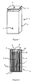
- a lithium-ion battery with liquid electrolyte illustrated by way of example with Figures 1 and 2 , comprises a housing 1 consisting of an upper face 3, a lower face 4 and a side wall 5 delimiting a cavity 2.
- the housing 1 is advantageously a large housing having a cavity volume 2 greater than 100 cm 3 .
- the housing 1 has two orifices, an electrolyte injection orifice 6 in the upper face 3 (at the top of the Figures 1 and 2 ) and a lateral orifice 7 formed in a lower zone of the side wall 5 (bottom of the Figures 1 and 2 ).
- lower zone is meant that part of the accumulator located below the median line dividing by half the upper part of the casing 1 of the lower part of the casing 1.
- the cavity 2 contains an electrode body 8 which may be, for example, consisting of a winding of alternately positive and negative electrodes, 8a and 8b, isolated from each other by a separator 8c.
- the electrode body 8 is disposed near the side wall 5 and rests in the lower part on the lower face 4.
- the positive electrode 8a is preferably based on lithiated transition metal oxide, supported by a aluminum strip (not shown) and the negative electrode 8b is based on carbon material, supported by a copper strip (not shown).
- the positive and negative electrode pairs, 8a and 8b, used may be LiNiCoAlO 2 / LiC 6 , LiFePO 4 / LiC 6 , or LiFePO 4 / Li 4 Ti 5 O 12 .
- the housing 1 comprises, in the lower part of the housing (at the bottom of Figures 1 and 2 ), a reservoir zone 9, intended to receive a determined quantity of liquid electrolyte solution.
- This reservoir zone 9 is delimited by the lower face 4, the lateral wall 5 and a plane A parallel to the lower face 4 and passing through the lower edge of the lateral orifice 7.
- This reservoir zone 9 is dimensioned to be able to contain between 5 % and 25% of the total volume of the housing 1, preferably 10%.
- the lateral orifice 7 is arranged so as to adjust the size of the reservoir zone 9 as a function of the external dimensions of the casing 1.
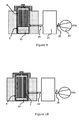
- the device comprises a fixed part 11 and a mobile part 12, sliding along two slides 13, of an open position ( figure 3 ) to a closed position ( figure 4 ).
- the housing 1 In open position, as shown in figure 3 , the housing 1 is disposed in a first housing 14, having a shape complementary to at least a portion of the housing 1.
- the movable portion 12 is engaged in the two rails 13 by two guide pins 15 and slides to the closed position ( figure 4 ).
- a second housing 16, located on the movable portion 12 has a shape complementary to at least a portion of the housing 1, so that once the movable portion 12 abuts against the fixed portion 11, the housing 1 is held in place .
- the upper part of the housing 1 (at the top of the figure 6 ) then exceeds two fixed and movable parts, 11 and 12, joined.
- a cover 17, having a shape complementary to this upper part can then be arranged on the upper part of the casing 1, so as to cover the upper face 3.
- the fixed and mobile parts, 11 and 12, and the cover 17 constitute in the closed position, a housing of complementary shape of the housing 1 and hold it fixedly.
- the cover 17 has a central orifice plugged by a cover 18.
- the fixed and mobile parts, 11 and 12 can form with the cover 17, a one-piece assembly coming to fit on the housing 1.
- the electrolyte injection port 6 is positioned at the top of the device (at the top of the figure 6 ), with respect to the cover 18.
- the cover 18 is airtight and preferably made of deformable material, for example silicone.
- a first seal 19 is disposed between the cover 17 and the upper face 3. The cover 18 associated with the first seal 19 makes it possible to close the electrolyte injection orifice 6 in a sealed manner.
- a needle 27 can, however, penetrate into the cavity 2 of the housing 1 through the cover 18 and the electrolyte injection port 6 ( figure 7 ).
- the lateral orifice 7 is disposed in the axis of a through-hole 20 of the mobile part 12, opening on one side in the second housing 16 and on the other side on the outside of the device ( figure 4 ).
- the electrolyte injection orifice 6 and the lateral orifice 7 are small, preferably circular, with a diameter of less than or equal to 2 mm in order to reduce the risk of leakage during the various filling operations and also after filling, once closed and sealed.
- a reservoir 21 is sealingly connected, by a first conduit 22a, to the through hole 20 and, by a second conduit 22b, to a vacuum pump 23.
- the first and second conduits, 22a and 22b, are respectively provided with a two-way valve 24 and a three-way valve 25 for creating or breaking the vacuum.
- the valve 24 is also used to actuate the opening and closing of the passage of the liquid electrolyte solution to the reservoir 21.
- the reservoir 21 can trap the liquid electrolyte solution by any known method, for example, by cooling.
- the valve 25 may also be connected to a supply of inert gas, for example nitrogen or argon, to purge the cavity 2.
- a second seal 26 is disposed between the side wall 5 of the housing 1 and the inner wall of the second housing 16, around the lateral orifice 7 ( figure 6 ).
- the first and second seals, 19 and 26, are advantageously seals resistant to the liquid electrolyte solution, for example, rubber type seal "Viton".
- the fixed and mobile parts, 11 and 12, as well as the cover 17 can be automatically controlled by automatic means, not illustrated, and managed by a logical system.
- the valves 24 and 25 may be electromechanical valves actuated by a programmable logic controller.
- the housing 1 is held in its housing by the fixed and mobile parts, 11 and 12, and the cover 17.
- the electrolyte injection port 6 is then closed by the cover 18.
- the vacuum pump 23 is then actuated while the valve 24 is open and the valve 25 is placed in a first open position, in which the reservoir 21 is connected to the vacuum pump 23.
- the vacuum pump 23 is stopped when the pressure reaches a predetermined value, lower than the atmospheric pressure.
- This pressure is advantageously between 100 and 300 mbar, preferably equal to 200 mbar. This pressure is defined according to the vapor pressure of the electrolyte solution.
- valves 24 and 25 are then closed.
- the lateral orifice 7 is then sealed.
- a first predetermined quantity of liquid electrolyte solution is then injected through the cover 18, through the electrolyte injection port 6, preferably by means of a needle 27.
- the use of a needle 27 is advantageous because it allows easy removal of the exact amount of liquid to be injected.
- the needle 27 pierces the lid 18, while maintaining the pressure inside the cavity 2, lower than the atmospheric pressure. Under the effect of the depression, the liquid electrolyte solution vaporizes and effectively penetrates the electrode body 8. The vaporization promotes the penetration of the ionic liquid electrolyte into the pores of the electrodes, 8a and 8b, and separators 8c.
- the impregnation is then performed homogeneously in the outer electrode layers but also in the inner layers of the electrode body 8.
- the vaporization of the liquid electrolyte restores the atmospheric pressure in the cavity 2.
- the amount of solution electrolyte injected liquid is a function of the volume of the housing 1. Almost all the injected liquid is advantageously vaporized. Depression promotes impregnation by improving vaporization for a solvent-based liquid electrolyte or diffusion for an ionic liquid electrolyte.
- the tank 21 is pressurized by switching the valve 25. 21 is then placed in communication with the cavity 2 by opening the valve 24 ( figure 8 ). The lateral orifice 7 is then connected to the atmospheric pressure, thereby putting the cavity 2 at atmospheric pressure.
- a second quantity of liquid electrolyte solution is injected through the electrolyte injection orifice 6, through the cover 18 in a manner identical to the first injection.
- the liquid electrolyte solution then flows to the reservoir zone 9 located below the lateral orifice 7, which fills up progressively.
- the volume delimited by the reservoir zone 9 corresponds to the maximum volume necessary for the impregnation of the electrode body 8.
- the lower part of the electrode body 8 (at the bottom of the figure 9 )
- the electrolyte solution 10 migrates into the electrode body 8 by capillarity and continues the impregnation.
- the first impregnation of the vaporized electrolyte solution promotes the reduction of the interactions between the liquid electrolyte solution 10 and the electrode walls, 8a and 8b, and the separators 8c.
- the migration of the electrolyte solution 10 then takes place more easily inside the electrode body 8. This effect is particularly marked for ionic liquid electrolyte solutions, viscous and not very wettable.
- This process is particularly advantageous for liquid electrolyte solutions having a viscosity greater than 100 centipoise (cP), ie 0.1 Pa.s or for liquid electrolyte solutions having an angle of contact with the electrode body 8 between 35 ° and 70 °.
- cP centipoise
- ionic liquid electrolyte PP 13 TFSI comprising LiTFSI at a concentration of 1.6 mol.l -1 with 5% by volume of vinyl ethylene carbonate and a box of 100 cm 3 : 30 cm 3 of a first quantity of ionic liquid electrolyte solution is injected. After 15 min, a second quantity of ionic liquid electrolyte solution of 10 cm 3 is injected at atmospheric pressure. According to this filling method, the battery box 1 is filled in about 15 minutes.
- the first quantity of liquid electrolyte solution corresponds to a value of between 45% and 95%, preferably 75%, of the total quantity of injected liquid electrolyte solution.
- the first and second injections of liquid electrolyte solution 10 partially fill the reservoir zone 9.
- the quantity of injected liquid electrolyte solution is only partially vaporized.
- the non-vaporized liquid is then collected in the reservoir zone 9 and partially fills it.
- the second injection of electrolyte solution then completes the reservoir zone 9.
- the excess of injected liquid electrolyte solution is discharged through the lateral orifice 7 (on the right on the figure 9 ) to the tank 21.
- the excess liquid electrolyte solution can advantageously be removed by putting the cavity 2 under vacuum again by switching the valves. 24 and 25 ( figure 10 ).
- the quality of the impregnation promotes the ion exchange even in the inner layers of the electrode stack, 8a and 8b, and has the effect of a stability of the performance of the accumulator.
- the electrolyte injection port 6 and the lateral orifice 7 are then closed tightly and permanently, according to any known method.
- the filling process may comprise more than two successive injections of liquid electrolyte solution.
- the creation of the depression in the housing 1 and the first injection of liquid electrolyte solution can be performed simultaneously.
- the migration of the liquid electrolyte solution is then favored.
- the filling method described above makes it possible to impregnate the accumulators, preferably of large size, according to a simple, inexpensive and fast process. Indeed, for the implementation of the method, it is not necessary to use a device comprising a vacuum chamber since only the cavity 2 of the accumulator is evacuated.
- the quantity of injected liquid electrolyte solution can be predefined in order to be limited only to the necessary volume.
- the volumes of electrolyte solution and inert gas needed to fill the battery packs are, therefore, much smaller than in conventional methods.
- the cost and the filling time are reduced.
- the liquid electrolyte accumulator and the method of the present invention are particularly suitable for lithium-ion accumulators using nonvolatile and non-flammable ionic liquid electrolyte solutions. They minimize the risk of leakage and provide reliable, secure batteries while maintaining high performance.
Landscapes
- Chemical & Material Sciences (AREA)
- Chemical Kinetics & Catalysis (AREA)
- Electrochemistry (AREA)
- General Chemical & Material Sciences (AREA)
- Engineering & Computer Science (AREA)
- Manufacturing & Machinery (AREA)
- Filling, Topping-Up Batteries (AREA)
- Secondary Cells (AREA)
Claims (8)
- Flüssigkeitselektrolyt-Batterie mit einem Gehäuse (1), das eine Oberseite (3), eine Unterseite (4) und eine Seitenwand (5) aufweist, welche einen Hohlraum (2) umgrenzen, wobei die Oberseite (3) eine Elektrolyt-Einspritzöffnung (6) aufweist und eine seitliche Öffnung (7) in einem unteren Bereich der Seitenwand (5) gebildet ist,
dadurch gekennzeichnet,
dass ein Reservoirbereich (9) von der Unterseite (4), der Seitenwand (5) und einer Ebene (A), die parallel zur Unterseite (4) und am unteren Rand der seitlichen Öffnung (7) vorbei verläuft, umgrenzt wird, und dass der Hohlraum (2) einen Elektrodenkörper (8) enthält, der sich zumindest mit einem Teil in dem genannten Reservoirbereich (9) befindet. - Batterie nach Anspruch 1,
dadurch gekennzeichnet,
dass der Reservoirbereich (9) so bemessen ist, dass er zwischen 5 % und 25 % des Gesamtvolumens des Gehäuses (1) enthalten kann. - Verfahren zum Füllen einer Batterie nach einem der Ansprüche 1 und 2, dadurch gekennzeichnet,
dass es aufeinander folgend umfasst:- Verschließen der Elektrolyt-Einspritzöffnung (6) mittels eines Deckels (18),- Betätigen einer Vakuumpumpe (23), die mit der seitlichen Öffnung (7) verbunden ist, bis der Druck im Hohlraum (2) einen vorbestimmten Wert erreicht, der unter dem atmosphärischen Druck liegt,- Verschließen der seitlichen Öffnung (7),- ein erstes Einspritzen einer ersten vorbestimmten Menge Flüssigkeitselektrolyt-I-ösung durch den Deckel (18),- nach einer vorbestimmten Dauer Anschließen der seitlichen Öffnung (7) an den atmosphärischen Druck,- ein zweites Einspritzen einer zweiten vorbestimmten Menge Flüssigkeitselektrolyt-Lösung durch den Deckel (18), um den Reservoirbereich (9) des Gehäuses (1), der sich unterhalb der seitlichen Öffnung (7) befindet, zumindest teilweise mit Flüssigkeitselektrolyt zu füllen, und- endgültiges Verschließen der Elektrolyt-Einspritzöffnung (6) und der seitlichen Öffnung (7). - Füllverfahren nach Anspruch 3,
dadurch gekennzeichnet,
dass die Flüssigkeitselektrolyt-Lösung eine Viskosität von mehr als 0,1 Pa.s. aufweist. - Füllverfahren nach einem der Ansprüche 3 und 4,
dadurch gekennzeichnet,
dass, indem der Hohlraum (2) einen Elektrodenkörper (8) enthält, die Flüssigkeitselektrolyt-Lösung (10) einen Kontaktwinkel mit dem Elektrodenkörper (8) aufweist, der zwischen 35° und 70° beträgt. - Füllverfahren nach einem der Ansprüche 3 bis 5,
dadurch gekennzeichnet,
dass der genannte Druck im Hohlraum (2) zwischen 100 und 300 mBar beträgt. - Füllverfahren nach Anspruch 6,
dadurch gekennzeichnet,
dass der Druck im Hohlraum (2) 200 mBar beträgt. - Füllverfahren nach einem der Ansprüche 3 bis 7,
dadurch gekennzeichnet,
dass das erste und das zweite Einspritzen mit Hilfe einer Nadel (27) durch den Deckel (18) aus verformbarem Material erfolgt.
Priority Applications (1)
| Application Number | Priority Date | Filing Date | Title |
|---|---|---|---|
| PL09817277T PL2329546T3 (pl) | 2008-09-30 | 2009-09-17 | Akumulator z elektrolitem ciekłym i sposób napełniania |
Applications Claiming Priority (2)
| Application Number | Priority Date | Filing Date | Title |
|---|---|---|---|
| FR0805380A FR2936653B1 (fr) | 2008-09-30 | 2008-09-30 | Accumulateur a electrolyte liquide et procede de remplissage |
| PCT/EP2009/062074 WO2010037640A1 (fr) | 2008-09-30 | 2009-09-17 | Accumulateur a electrolyte liquide et procede de remplissage |
Publications (2)
| Publication Number | Publication Date |
|---|---|
| EP2329546A1 EP2329546A1 (de) | 2011-06-08 |
| EP2329546B1 true EP2329546B1 (de) | 2012-11-21 |
Family
ID=40251630
Family Applications (1)
| Application Number | Title | Priority Date | Filing Date |
|---|---|---|---|
| EP09817277A Not-in-force EP2329546B1 (de) | 2008-09-30 | 2009-09-17 | Batterie mit flüssigelektrolyt und füllverfahren dafür |
Country Status (8)
| Country | Link |
|---|---|
| US (1) | US8568911B2 (de) |
| EP (1) | EP2329546B1 (de) |
| JP (1) | JP5558472B2 (de) |
| CN (1) | CN102171853B (de) |
| ES (1) | ES2398806T3 (de) |
| FR (1) | FR2936653B1 (de) |
| PL (1) | PL2329546T3 (de) |
| WO (1) | WO2010037640A1 (de) |
Families Citing this family (20)
| Publication number | Priority date | Publication date | Assignee | Title |
|---|---|---|---|---|
| US20130143110A1 (en) * | 2011-12-01 | 2013-06-06 | Roger Neil Bull | System and method for enclosing an energy storage cell |
| DE102011088682A1 (de) * | 2011-12-15 | 2013-06-20 | Robert Bosch Gmbh | Elektrolytflüssigkeitsdosiereinrichtung für Lithium-Zellen |
| US9859569B2 (en) * | 2012-02-07 | 2018-01-02 | Nissan Motor Co., Ltd. | Method and device for manufacturing film-wrapped electrical device |
| DE102012211153A1 (de) | 2012-06-28 | 2014-04-10 | Evonik Litarion Gmbh | Selbstlimitierendes Elektrolyt-Befüllverfahren |
| JP2014022336A (ja) * | 2012-07-23 | 2014-02-03 | Sharp Corp | 非水系二次電池の注液装置および注液方法 |
| FR3002483B1 (fr) | 2013-02-25 | 2016-03-11 | Daniel Andre Gastel | Procede d'obtention d'une cale pelable tridimensionnelle et cale pelable tridimensionnelle ainsi obtenue |
| FR3006937B1 (fr) | 2013-06-14 | 2016-01-22 | Yann Maurice Gastel | Procede d'obtention d'une cale pelable non plane et cale pelable non plane ainsi obtenue |
| KR101558049B1 (ko) * | 2013-09-30 | 2015-10-06 | 주식회사 엘지화학 | 이차전지의 제조 방법 |
| KR102031276B1 (ko) * | 2016-08-26 | 2019-10-11 | 주식회사 엘지화학 | 이차전지 및 이차전지의 전해액 보충 방법 |
| US20180108902A1 (en) * | 2016-10-17 | 2018-04-19 | The Paper Battery Company, Inc. | Filling and sealing energy storage structures, and fabrication tools therefor |
| TWI638478B (zh) * | 2017-06-16 | 2018-10-11 | 有量科技股份有限公司 | 鋰電池芯的除氣方法 |
| CN109148787B (zh) * | 2017-06-28 | 2021-06-11 | 有量科技股份有限公司 | 锂电池芯的除气方法 |
| DE102018204522B4 (de) * | 2018-03-23 | 2025-02-13 | LioVolt GmbH | Verfahren zur Herstellung eines Bipolarbatteriezellen-Stapels |
| JP7231188B2 (ja) * | 2018-10-02 | 2023-03-01 | エリーパワー株式会社 | リチウムイオン電池の製造方法 |
| DE102019201021A1 (de) * | 2019-01-28 | 2020-08-13 | Volkswagen Aktiengesellschaft | Batterie mit mittels einer Druckdifferenz wirkender Dichtung |
| DE102019134427A1 (de) * | 2019-12-16 | 2021-06-17 | Bayerische Motoren Werke Aktiengesellschaft | Lithium-Ionen-Batterie mit verlängerter Lebensdauer |
| EP4167330B1 (de) * | 2020-06-15 | 2025-11-19 | LG Energy Solution, Ltd. | Sekundärbatterie und verfahren zur herstellung |
| CN112018448B (zh) * | 2020-07-30 | 2022-01-28 | 江西省海思特新能源有限公司 | 一种寿命长的锂电池 |
| DE102022103025A1 (de) | 2022-02-09 | 2023-08-10 | Volkswagen Aktiengesellschaft | Batteriezelle sowie Verfahren zur Befüllung einer solchen Batteriezelle |
| IT202200021240A1 (it) * | 2022-10-14 | 2024-04-14 | I M A Industria Macch Automatiche S P A In Sigla Ima S P A | Procedimento e linea di produzione di batterie. |
Family Cites Families (17)
| Publication number | Priority date | Publication date | Assignee | Title |
|---|---|---|---|---|
| GB118062A (de) * | 1917-10-30 | |||
| GB200731A (en) * | 1922-10-12 | 1923-07-19 | George Albert Penrose | An improvement on maintenance and cleansing of secondary batteries |
| US1823448A (en) * | 1925-08-15 | 1931-09-15 | George W Hebbeler | Storage battery |
| GB295516A (en) * | 1927-09-01 | 1928-08-16 | Oldham & Son Ltd | Improvements in or connected with galvanic batteries |
| US3708345A (en) * | 1970-01-08 | 1973-01-02 | Gulf Oil Corp | Electrochemical energy conversion system |
| US4061163A (en) * | 1976-07-06 | 1977-12-06 | Gte Sylvania Incorporated | Method of filling electrochemical cells with electrolyte |
| US4695519A (en) * | 1981-05-18 | 1987-09-22 | Medtronic, Inc. | Electrochemical cell construction and fill method |
| JPS60246557A (ja) * | 1984-05-18 | 1985-12-06 | Matsushita Electric Ind Co Ltd | 鉛蓄電池の電解液注液法 |
| US5558947A (en) * | 1995-04-14 | 1996-09-24 | Robison; George D. | Rechargeable battery system and method and metal-air electrochemical cell for use therein |
| US5849431A (en) * | 1995-09-27 | 1998-12-15 | Sony Corporation | High capacity secondary battery of jelly roll type |
| US6387561B1 (en) * | 1998-10-13 | 2002-05-14 | Ngk Insulators, Ltd. | Electrolyte-solution filling method and battery structure of lithium secondary battery |
| JP3470051B2 (ja) * | 1998-11-25 | 2003-11-25 | 日本碍子株式会社 | リチウム二次電池 |
| JP3464612B2 (ja) * | 1998-10-13 | 2003-11-10 | 日本碍子株式会社 | リチウム二次電池の製造方法 |
| JP3445171B2 (ja) * | 1998-11-04 | 2003-09-08 | 日本碍子株式会社 | リチウム二次電池 |
| DE29915950U1 (de) * | 1999-09-10 | 1999-12-30 | CMW Automation GmbH, 65594 Runkel | Vorrichtung zum Elektrolytbefüllen der Zellen eines Akkumulators |
| JP2001110400A (ja) * | 1999-10-04 | 2001-04-20 | Nec Mobile Energy Kk | 電解液注入装置および電解液注入方法 |
| CN101212037A (zh) * | 2006-12-31 | 2008-07-02 | 上海比亚迪有限公司 | 一种电池的注液方法 |
-
2008
- 2008-09-30 FR FR0805380A patent/FR2936653B1/fr not_active Expired - Fee Related
-
2009
- 2009-09-17 CN CN200980138384.0A patent/CN102171853B/zh not_active Expired - Fee Related
- 2009-09-17 PL PL09817277T patent/PL2329546T3/pl unknown
- 2009-09-17 WO PCT/EP2009/062074 patent/WO2010037640A1/fr not_active Ceased
- 2009-09-17 US US13/119,588 patent/US8568911B2/en not_active Expired - Fee Related
- 2009-09-17 ES ES09817277T patent/ES2398806T3/es active Active
- 2009-09-17 EP EP09817277A patent/EP2329546B1/de not_active Not-in-force
- 2009-09-17 JP JP2011528294A patent/JP5558472B2/ja not_active Expired - Fee Related
Also Published As
| Publication number | Publication date |
|---|---|
| CN102171853B (zh) | 2014-01-01 |
| FR2936653A1 (fr) | 2010-04-02 |
| JP2012504303A (ja) | 2012-02-16 |
| US8568911B2 (en) | 2013-10-29 |
| PL2329546T3 (pl) | 2013-04-30 |
| JP5558472B2 (ja) | 2014-07-23 |
| WO2010037640A1 (fr) | 2010-04-08 |
| ES2398806T3 (es) | 2013-03-21 |
| CN102171853A (zh) | 2011-08-31 |
| EP2329546A1 (de) | 2011-06-08 |
| US20110171503A1 (en) | 2011-07-14 |
| FR2936653B1 (fr) | 2011-02-11 |
Similar Documents
| Publication | Publication Date | Title |
|---|---|---|
| EP2329546B1 (de) | Batterie mit flüssigelektrolyt und füllverfahren dafür | |
| EP2984697B1 (de) | Elektrochemische lithiumspeicherbatterie mit einem gehäuse mit verbesserter wärmeableitung, batteriepack und zugehöriges herstellungsverfahren | |
| EP2933869B1 (de) | Verfahren zur herstellung einer sekundärbatterie mit nichtwässrigem elektrolyten | |
| FR2965111B1 (fr) | Element de regulation de la pression gazeuse interne dans des cellules a ions lithium | |
| EP3179532B1 (de) | Dichter querträger vom typ glas-metall, seine verwendung für elektrochemischen lithiumakkumulator und entsprechendes herstellungsverfahren | |
| EP3130020A1 (de) | Elektrochemischer lithium-ionen-akku mit direkt an die elektrodenanordnung angeschlossenem anschluss und zugehöriges herstellungsverfahren | |
| EP3100315B1 (de) | Verfahren zur regeneration der kapazität einer elektrochemischen lithiumbatterie sowie zugehöriges batteriegehäuse und batterie | |
| JP3464612B2 (ja) | リチウム二次電池の製造方法 | |
| EP3021383B1 (de) | Verfahren zum wasserdichten abdichten einer öffnung eines akkumulatorgehäuses, und durch dieses verfahren abgedichtetes gehäuse | |
| EP3384550B1 (de) | Verfahren zur regeneration der kapazität eines metal-ion akkumulators und zugeordneter akkumulator | |
| JP2021103658A (ja) | 非水電解液二次電池 | |
| JP2010073400A (ja) | 電解液注入方法、及び、電解液注入装置 | |
| WO2025224353A1 (fr) | Cellule en sachet de batterie électrique et procédé de fabrication correspondant | |
| FR2601819A1 (fr) | Pile electrochimique et son procede de fabrication | |
| EP3319150B1 (de) | Verfahren zum regenerieren eines metall-ionen-akkumulators | |
| KR102933065B1 (ko) | 가용성 기체 포화 전해액을 이용한 전지셀 제조방법 | |
| KR101986200B1 (ko) | 진공 생성기를 포함하는 전해액 주액 장치 및 이를 사용하여 제조된 전지셀 | |
| EP4468438A1 (de) | Verfahren zur herstellung einer lithium-metall- oder natrium-metall-festkörperbatterie aus einem elektrochemischen flüssigelektrolyt-akkumulator zur thermischen unschädlichmachung | |
| FR3157002A1 (fr) | Procédé de recyclage d’accumulateurs électrochimiques métal-ion hors d’usage et/ou en fin de vie), Appareil et Installation de recyclage associés. | |
| FR3016736A1 (fr) | Batterie lithium-ion (li-ion) a capacite augmentee par augmentation de la hauteur disponible a l'interieur du boitier | |
| JP2022086223A (ja) | 非水電解液二次電池の製造方法 |
Legal Events
| Date | Code | Title | Description |
|---|---|---|---|
| PUAI | Public reference made under article 153(3) epc to a published international application that has entered the european phase |
Free format text: ORIGINAL CODE: 0009012 |
|
| 17P | Request for examination filed |
Effective date: 20110314 |
|
| AK | Designated contracting states |
Kind code of ref document: A1 Designated state(s): AT BE BG CH CY CZ DE DK EE ES FI FR GB GR HR HU IE IS IT LI LT LU LV MC MK MT NL NO PL PT RO SE SI SK SM TR |
|
| AX | Request for extension of the european patent |
Extension state: AL BA RS |
|
| DAX | Request for extension of the european patent (deleted) | ||
| GRAP | Despatch of communication of intention to grant a patent |
Free format text: ORIGINAL CODE: EPIDOSNIGR1 |
|
| GRAS | Grant fee paid |
Free format text: ORIGINAL CODE: EPIDOSNIGR3 |
|
| GRAA | (expected) grant |
Free format text: ORIGINAL CODE: 0009210 |
|
| AK | Designated contracting states |
Kind code of ref document: B1 Designated state(s): AT BE BG CH CY CZ DE DK EE ES FI FR GB GR HR HU IE IS IT LI LT LU LV MC MK MT NL NO PL PT RO SE SI SK SM TR |
|
| REG | Reference to a national code |
Ref country code: GB Ref legal event code: FG4D Free format text: NOT ENGLISH |
|
| REG | Reference to a national code |
Ref country code: CH Ref legal event code: EP |
|
| REG | Reference to a national code |
Ref country code: AT Ref legal event code: REF Ref document number: 585478 Country of ref document: AT Kind code of ref document: T Effective date: 20121215 |
|
| REG | Reference to a national code |
Ref country code: IE Ref legal event code: FG4D Free format text: LANGUAGE OF EP DOCUMENT: FRENCH |
|
| REG | Reference to a national code |
Ref country code: DE Ref legal event code: R096 Ref document number: 602009011458 Country of ref document: DE Effective date: 20130117 |
|
| REG | Reference to a national code |
Ref country code: ES Ref legal event code: FG2A Ref document number: 2398806 Country of ref document: ES Kind code of ref document: T3 Effective date: 20130321 |
|
| REG | Reference to a national code |
Ref country code: NL Ref legal event code: VDEP Effective date: 20121121 |
|
| REG | Reference to a national code |
Ref country code: AT Ref legal event code: MK05 Ref document number: 585478 Country of ref document: AT Kind code of ref document: T Effective date: 20121121 |
|
| REG | Reference to a national code |
Ref country code: LT Ref legal event code: MG4D |
|
| PG25 | Lapsed in a contracting state [announced via postgrant information from national office to epo] |
Ref country code: SE Free format text: LAPSE BECAUSE OF FAILURE TO SUBMIT A TRANSLATION OF THE DESCRIPTION OR TO PAY THE FEE WITHIN THE PRESCRIBED TIME-LIMIT Effective date: 20121121 Ref country code: FI Free format text: LAPSE BECAUSE OF FAILURE TO SUBMIT A TRANSLATION OF THE DESCRIPTION OR TO PAY THE FEE WITHIN THE PRESCRIBED TIME-LIMIT Effective date: 20121121 Ref country code: LT Free format text: LAPSE BECAUSE OF FAILURE TO SUBMIT A TRANSLATION OF THE DESCRIPTION OR TO PAY THE FEE WITHIN THE PRESCRIBED TIME-LIMIT Effective date: 20121121 Ref country code: NO Free format text: LAPSE BECAUSE OF FAILURE TO SUBMIT A TRANSLATION OF THE DESCRIPTION OR TO PAY THE FEE WITHIN THE PRESCRIBED TIME-LIMIT Effective date: 20130221 |
|
| REG | Reference to a national code |
Ref country code: PL Ref legal event code: T3 |
|
| PG25 | Lapsed in a contracting state [announced via postgrant information from national office to epo] |
Ref country code: LV Free format text: LAPSE BECAUSE OF FAILURE TO SUBMIT A TRANSLATION OF THE DESCRIPTION OR TO PAY THE FEE WITHIN THE PRESCRIBED TIME-LIMIT Effective date: 20121121 Ref country code: PT Free format text: LAPSE BECAUSE OF FAILURE TO SUBMIT A TRANSLATION OF THE DESCRIPTION OR TO PAY THE FEE WITHIN THE PRESCRIBED TIME-LIMIT Effective date: 20130321 Ref country code: GR Free format text: LAPSE BECAUSE OF FAILURE TO SUBMIT A TRANSLATION OF THE DESCRIPTION OR TO PAY THE FEE WITHIN THE PRESCRIBED TIME-LIMIT Effective date: 20130222 Ref country code: SI Free format text: LAPSE BECAUSE OF FAILURE TO SUBMIT A TRANSLATION OF THE DESCRIPTION OR TO PAY THE FEE WITHIN THE PRESCRIBED TIME-LIMIT Effective date: 20121121 |
|
| PG25 | Lapsed in a contracting state [announced via postgrant information from national office to epo] |
Ref country code: AT Free format text: LAPSE BECAUSE OF FAILURE TO SUBMIT A TRANSLATION OF THE DESCRIPTION OR TO PAY THE FEE WITHIN THE PRESCRIBED TIME-LIMIT Effective date: 20121121 |
|
| PG25 | Lapsed in a contracting state [announced via postgrant information from national office to epo] |
Ref country code: CZ Free format text: LAPSE BECAUSE OF FAILURE TO SUBMIT A TRANSLATION OF THE DESCRIPTION OR TO PAY THE FEE WITHIN THE PRESCRIBED TIME-LIMIT Effective date: 20121121 Ref country code: BG Free format text: LAPSE BECAUSE OF FAILURE TO SUBMIT A TRANSLATION OF THE DESCRIPTION OR TO PAY THE FEE WITHIN THE PRESCRIBED TIME-LIMIT Effective date: 20130221 Ref country code: EE Free format text: LAPSE BECAUSE OF FAILURE TO SUBMIT A TRANSLATION OF THE DESCRIPTION OR TO PAY THE FEE WITHIN THE PRESCRIBED TIME-LIMIT Effective date: 20121121 Ref country code: SK Free format text: LAPSE BECAUSE OF FAILURE TO SUBMIT A TRANSLATION OF THE DESCRIPTION OR TO PAY THE FEE WITHIN THE PRESCRIBED TIME-LIMIT Effective date: 20121121 Ref country code: DK Free format text: LAPSE BECAUSE OF FAILURE TO SUBMIT A TRANSLATION OF THE DESCRIPTION OR TO PAY THE FEE WITHIN THE PRESCRIBED TIME-LIMIT Effective date: 20121121 |
|
| PG25 | Lapsed in a contracting state [announced via postgrant information from national office to epo] |
Ref country code: NL Free format text: LAPSE BECAUSE OF FAILURE TO SUBMIT A TRANSLATION OF THE DESCRIPTION OR TO PAY THE FEE WITHIN THE PRESCRIBED TIME-LIMIT Effective date: 20121121 Ref country code: RO Free format text: LAPSE BECAUSE OF FAILURE TO SUBMIT A TRANSLATION OF THE DESCRIPTION OR TO PAY THE FEE WITHIN THE PRESCRIBED TIME-LIMIT Effective date: 20121121 |
|
| PLBE | No opposition filed within time limit |
Free format text: ORIGINAL CODE: 0009261 |
|
| STAA | Information on the status of an ep patent application or granted ep patent |
Free format text: STATUS: NO OPPOSITION FILED WITHIN TIME LIMIT |
|
| 26N | No opposition filed |
Effective date: 20130822 |
|
| REG | Reference to a national code |
Ref country code: DE Ref legal event code: R097 Ref document number: 602009011458 Country of ref document: DE Effective date: 20130822 |
|
| PG25 | Lapsed in a contracting state [announced via postgrant information from national office to epo] |
Ref country code: HR Free format text: LAPSE BECAUSE OF FAILURE TO SUBMIT A TRANSLATION OF THE DESCRIPTION OR TO PAY THE FEE WITHIN THE PRESCRIBED TIME-LIMIT Effective date: 20130731 |
|
| BERE | Be: lapsed |
Owner name: CENTRE NATIONAL DE LA RECHERCHE SCIENTIFIQUE Effective date: 20130930 Owner name: COMMISSARIAT A L'ENERGIE ATOMIQUE ET AUX ENERGIES Effective date: 20130930 |
|
| PG25 | Lapsed in a contracting state [announced via postgrant information from national office to epo] |
Ref country code: MC Free format text: LAPSE BECAUSE OF FAILURE TO SUBMIT A TRANSLATION OF THE DESCRIPTION OR TO PAY THE FEE WITHIN THE PRESCRIBED TIME-LIMIT Effective date: 20121121 |
|
| REG | Reference to a national code |
Ref country code: CH Ref legal event code: PL |
|
| REG | Reference to a national code |
Ref country code: IE Ref legal event code: MM4A |
|
| PG25 | Lapsed in a contracting state [announced via postgrant information from national office to epo] |
Ref country code: LI Free format text: LAPSE BECAUSE OF NON-PAYMENT OF DUE FEES Effective date: 20130930 Ref country code: IE Free format text: LAPSE BECAUSE OF NON-PAYMENT OF DUE FEES Effective date: 20130917 Ref country code: BE Free format text: LAPSE BECAUSE OF NON-PAYMENT OF DUE FEES Effective date: 20130930 Ref country code: CH Free format text: LAPSE BECAUSE OF NON-PAYMENT OF DUE FEES Effective date: 20130930 |
|
| PG25 | Lapsed in a contracting state [announced via postgrant information from national office to epo] |
Ref country code: SM Free format text: LAPSE BECAUSE OF FAILURE TO SUBMIT A TRANSLATION OF THE DESCRIPTION OR TO PAY THE FEE WITHIN THE PRESCRIBED TIME-LIMIT Effective date: 20121121 |
|
| PG25 | Lapsed in a contracting state [announced via postgrant information from national office to epo] |
Ref country code: CY Free format text: LAPSE BECAUSE OF FAILURE TO SUBMIT A TRANSLATION OF THE DESCRIPTION OR TO PAY THE FEE WITHIN THE PRESCRIBED TIME-LIMIT Effective date: 20121121 Ref country code: TR Free format text: LAPSE BECAUSE OF FAILURE TO SUBMIT A TRANSLATION OF THE DESCRIPTION OR TO PAY THE FEE WITHIN THE PRESCRIBED TIME-LIMIT Effective date: 20121121 Ref country code: MT Free format text: LAPSE BECAUSE OF FAILURE TO SUBMIT A TRANSLATION OF THE DESCRIPTION OR TO PAY THE FEE WITHIN THE PRESCRIBED TIME-LIMIT Effective date: 20121121 |
|
| PG25 | Lapsed in a contracting state [announced via postgrant information from national office to epo] |
Ref country code: LU Free format text: LAPSE BECAUSE OF NON-PAYMENT OF DUE FEES Effective date: 20130917 Ref country code: MK Free format text: LAPSE BECAUSE OF FAILURE TO SUBMIT A TRANSLATION OF THE DESCRIPTION OR TO PAY THE FEE WITHIN THE PRESCRIBED TIME-LIMIT Effective date: 20121121 Ref country code: HU Free format text: LAPSE BECAUSE OF FAILURE TO SUBMIT A TRANSLATION OF THE DESCRIPTION OR TO PAY THE FEE WITHIN THE PRESCRIBED TIME-LIMIT; INVALID AB INITIO Effective date: 20090917 |
|
| PGFP | Annual fee paid to national office [announced via postgrant information from national office to epo] |
Ref country code: ES Payment date: 20150928 Year of fee payment: 7 Ref country code: GB Payment date: 20150921 Year of fee payment: 7 |
|
| PGFP | Annual fee paid to national office [announced via postgrant information from national office to epo] |
Ref country code: PL Payment date: 20150814 Year of fee payment: 7 |
|
| PGFP | Annual fee paid to national office [announced via postgrant information from national office to epo] |
Ref country code: IT Payment date: 20150915 Year of fee payment: 7 |
|
| PG25 | Lapsed in a contracting state [announced via postgrant information from national office to epo] |
Ref country code: IS Free format text: LAPSE BECAUSE OF FAILURE TO SUBMIT A TRANSLATION OF THE DESCRIPTION OR TO PAY THE FEE WITHIN THE PRESCRIBED TIME-LIMIT Effective date: 20121121 |
|
| REG | Reference to a national code |
Ref country code: FR Ref legal event code: PLFP Year of fee payment: 8 |
|
| PGFP | Annual fee paid to national office [announced via postgrant information from national office to epo] |
Ref country code: DE Payment date: 20160914 Year of fee payment: 8 |
|
| PGFP | Annual fee paid to national office [announced via postgrant information from national office to epo] |
Ref country code: FR Payment date: 20160928 Year of fee payment: 8 |
|
| GBPC | Gb: european patent ceased through non-payment of renewal fee |
Effective date: 20160917 |
|
| PG25 | Lapsed in a contracting state [announced via postgrant information from national office to epo] |
Ref country code: GB Free format text: LAPSE BECAUSE OF NON-PAYMENT OF DUE FEES Effective date: 20160917 |
|
| PG25 | Lapsed in a contracting state [announced via postgrant information from national office to epo] |
Ref country code: IT Free format text: LAPSE BECAUSE OF NON-PAYMENT OF DUE FEES Effective date: 20160917 |
|
| PG25 | Lapsed in a contracting state [announced via postgrant information from national office to epo] |
Ref country code: PL Free format text: LAPSE BECAUSE OF NON-PAYMENT OF DUE FEES Effective date: 20160917 |
|
| REG | Reference to a national code |
Ref country code: DE Ref legal event code: R119 Ref document number: 602009011458 Country of ref document: DE |
|
| PG25 | Lapsed in a contracting state [announced via postgrant information from national office to epo] |
Ref country code: ES Free format text: LAPSE BECAUSE OF NON-PAYMENT OF DUE FEES Effective date: 20160918 |
|
| REG | Reference to a national code |
Ref country code: FR Ref legal event code: ST Effective date: 20180531 |
|
| PG25 | Lapsed in a contracting state [announced via postgrant information from national office to epo] |
Ref country code: DE Free format text: LAPSE BECAUSE OF NON-PAYMENT OF DUE FEES Effective date: 20180404 |
|
| PG25 | Lapsed in a contracting state [announced via postgrant information from national office to epo] |
Ref country code: FR Free format text: LAPSE BECAUSE OF NON-PAYMENT OF DUE FEES Effective date: 20171002 |
|
| REG | Reference to a national code |
Ref country code: ES Ref legal event code: FD2A Effective date: 20181121 |