EP3021974B1 - Zentrifuge - Google Patents
Zentrifuge Download PDFInfo
- Publication number
- EP3021974B1 EP3021974B1 EP14750321.3A EP14750321A EP3021974B1 EP 3021974 B1 EP3021974 B1 EP 3021974B1 EP 14750321 A EP14750321 A EP 14750321A EP 3021974 B1 EP3021974 B1 EP 3021974B1
- Authority
- EP
- European Patent Office
- Prior art keywords
- rotor
- driveshaft
- locking
- locking elements
- end section
- Prior art date
- Legal status (The legal status is an assumption and is not a legal conclusion. Google has not performed a legal analysis and makes no representation as to the accuracy of the status listed.)
- Active
Links
Images



Classifications
-
- B—PERFORMING OPERATIONS; TRANSPORTING
- B04—CENTRIFUGAL APPARATUS OR MACHINES FOR CARRYING-OUT PHYSICAL OR CHEMICAL PROCESSES
- B04B—CENTRIFUGES
- B04B9/00—Drives specially designed for centrifuges; Arrangement or disposition of transmission gearing; Suspending or balancing rotary bowls
- B04B9/08—Arrangement or disposition of transmission gearing ; Couplings; Brakes
-
- B—PERFORMING OPERATIONS; TRANSPORTING
- B04—CENTRIFUGAL APPARATUS OR MACHINES FOR CARRYING-OUT PHYSICAL OR CHEMICAL PROCESSES
- B04B—CENTRIFUGES
- B04B9/00—Drives specially designed for centrifuges; Arrangement or disposition of transmission gearing; Suspending or balancing rotary bowls
- B04B9/08—Arrangement or disposition of transmission gearing ; Couplings; Brakes
- B04B2009/085—Locking means between drive shaft and rotor
-
- F—MECHANICAL ENGINEERING; LIGHTING; HEATING; WEAPONS; BLASTING
- F16—ENGINEERING ELEMENTS AND UNITS; GENERAL MEASURES FOR PRODUCING AND MAINTAINING EFFECTIVE FUNCTIONING OF MACHINES OR INSTALLATIONS; THERMAL INSULATION IN GENERAL
- F16D—COUPLINGS FOR TRANSMITTING ROTATION; CLUTCHES; BRAKES
- F16D1/00—Couplings for rigidly connecting two coaxial shafts or other movable machine elements
- F16D1/10—Quick-acting couplings in which the parts are connected by simply bringing them together axially
- F16D1/108—Quick-acting couplings in which the parts are connected by simply bringing them together axially having retaining means rotating with the coupling and acting by interengaging parts, i.e. positive coupling
Definitions
- the invention relates to a centrifuge according to the specified in the preamble of claim 1. Art.
- Centrifuges with removable rotor which have a device for axial locking of the rotor on the drive shaft and in which no complicated assembly and no special tools are required for locking.
- a centrifuge in which the rotor is automatically brought into a locking position when placing.
- a spring-loaded latch engages in a recess in the drive shaft, thereby ensuring an axial detection of the rotor.
- the drive shaft must penetrate to a not inconsiderable part in the rotor to provide sufficient attack surface for the locking mechanism, and that the locking takes place below the rotor. This requires a larger space requirement.
- the drive shaft is weakened by the arrangement of a part of the locking mechanism in the drive shaft. The speed and / or durability of such designs is therefore limited.
- a centrifuge known. This has a rotor bearing with a locking system, in which the rotor is fixed on the drive shaft.
- the locking system comprises axes extending perpendicularly to the axis of rotation and locking levers pivotable about the axes between a locking position and an unlocking position.
- the locking levers engage in the locking position in an annular groove in the drive shaft and fix the rotor on the shaft axially.
- the locking levers are speed-dependent automatically transferred from the unlocked position into the locking position.
- At about 600 RPM laboratory centrifuges often undergo the first resonance. The However, generic centrifuge can muster no significant axial holding force at these speeds.
- the WO 2011/054906 A1 discloses a centrifuge having a rotor connectable to a drive shaft via a locking mechanism.
- the locking mechanism has pawls which can be pivoted about axes extending parallel to the drive axis and which have a mass distribution such that they are held in the locking position as a function of rotational speed.
- the pawls engage in an annular groove of the drive shaft.
- the US 2008/0146429 A1 has only one locking element which is moved by a handle perpendicular to the drive shaft from an unlocking position to a locking position.
- From the JP 164 040 A is a generic centrifuge with quick release for connecting a rotor with a drive shaft known.
- An end portion of the drive shaft has a groove in which engage locking elements in the form of balls for locking the rotor on the drive shaft.
- a handle moves the balls via a relative movement to their base from a locking position to an unlocking position. The movement of the handle takes place in a direction parallel to the drive shaft.
- An opening wall defines an opening into which the drive shaft engages.
- the balls are introduced in a recess of an opening wall.
- the recess in the opening wall is assigned to the groove in the end region of the drive shaft.
- the groove is in the inserted state next to the recess in the opening wall, so that the ball can, if necessary, engage in the groove.
- centrifuges with quick-release buckles are from the JP 2001/205136 A and the WO 83/04379 A known.
- Object of the present invention is to provide while avoiding the disadvantages mentioned a centrifuge with a removable rotor, which has a simpler and safe quick release, which is above all independent of speed.
- the locking mechanism in the region of the rotor requires less space for the lock.
- the invention is based on the finding that it is possible to ensure a reliable axial determination in withdrawal direction of rotor and drive shaft when placing the rotor on the drive shaft by a closure device, wherein the drive shaft with a widened region engages through a rotor opening and a closing device between Rotor and widened area blocks the opening so that the rotor is fixed to the drive shaft in the withdrawal direction.
- the rotor is thereby securely arranged on the drive shaft and arranged safely and with easy-to-produce means in the centrifuge even at high speeds and the associated elastic deformation of components of the centrifuge.
- the centrifuge has a drive shaft with an end portion which tapers to the remaining portion of the drive shaft, wherein the taper may be gradual or erratic, and mounted on the drive shaft, axially removable in a removal direction rotor, further a bearing for the rotor, which is connected to the drive shaft and defines the rotor at least against the withdrawal direction, further comprises a built-in rotor quick release, by means of which the drive shaft and the rotor are fixed in the removal direction, and finally an opening in the rotor, through which the drive shaft engages with the end portion, and which is bounded by an opening wall.
- locking elements are provided on the rotor side for fixing the rotor relative to the drive shaft, which respectively partially surround the end region.
- the blocking elements are partially adjacent to the end region and opposite to the removal direction on the opening wall.
- the outer circumference formed by the blocking elements is greater than the inner circumference of the opening. This creates a wedge effect, which is exacerbated as soon as a force in the removal direction begins to act on the rotating rotor.
- the end portion has a widened portion that tapers to a remaining portion of the drive shaft.
- the quick release is provided with power transmission elements which connect the locking elements with a handle, and that the locking and / or unlocking of the quick release in each case by a movement of the handle and the power transmission elements in a direction parallel to the drive shaft. Over this locking and unlocking can be controlled directly and very precisely.
- This arrangement has the advantage that only a comparatively small end region of the drive shaft has to be used for axially locking the rotor and drive shaft and that it is possible to dispense with a locking mechanism which exerts a lateral force for fixing and in which a certain length of the drive shaft is required , Thus, a smaller footprint is achieved and a weakening of the drive shaft avoided.
- the locking elements are resiliently movable via at least one spring and biased in the direction of the drive shaft.
- an unwanted displacement of the locking elements can be counteracted from its intended position when the locking elements are elastically deflected by the spring so that the end portion is passable in its widest point with respect to the central axis of the drive shaft.
- a further structural simplification can be achieved in that the force transmission elements form the spring.
- the force transmission elements are spring loaded. This ensures that the locking elements, when they are initially displaced from the position of the rotor engaging the end portion of the drive shaft which engages through the opening, finally reach past the end area in the seating direction, rest against them and reliably fulfill their blocking effect.
- locking elements are at least partially adapted in shape to the shape of the end portion of the drive shaft.
- These Design of the locking elements allows a better fit between the end portion of the drive shaft and the quick release and between the quick release and the opening wall and reduces the material load, in particular the burden of the locking elements.
- the end region of the drive shaft is spherical in shape and in particular concavely rounded in the transition region from the ball to the drive shaft, since this makes it easier for the blocking elements to surround and abut the end region of the drive shaft and beyond the production of a positive connection between the end portion of the drive shaft and the quick release and between the quick release and the opening wall is simplified once again.
- the opening wall on a control surface for the locking elements which moves when inserting the rotor in the locking position of the quick release by moving against the withdrawal direction, the locking elements in the direction of the drive shaft and presses in locking position against the drive shaft. This further improves the controllability of the locking elements, as they easily slide against their minimum resistance to their locking position.
- An additional improvement in the stability of the axial determination of the rotor and the drive shaft can be achieved in that the control surface is formed so that in the locking position, the locking elements partially abut the end region on the end region and on the side facing away from the end region on the control surface issue. This results in a better fit between the end of the drive shaft and the quick release and between the quick release and the opening wall.
- control surface makes it possible to deflect the blocking elements during a movement in the withdrawal direction, ie when the quick-acting closure is opened. With this design, the quick release with relatively little effort can be easily unlocked.
- the unlocking direction and the removal direction are the same. This provides another possibility to make the structure of the quick release and the rotor simpler and more compact.
- the removal of the rotor can be designed so that the release of the quick release and the removal of the rotor are mechanically coupled together, because then only a single movement is required to simultaneously release the closure and remove the rotor from the centrifuge.
- a particularly secure locking can be achieved in that at least two, preferably three locking elements are provided, which are arranged at a uniform distance from each other.
- a pivot axis of the locking elements is perpendicular to the central axis of the drive shaft and the springs extend in the undeflected position of the pivot axis, relative to the central axis, down, in particular parallel to the central axis.
- the spring and the blocking element are integrally formed of the same material and surround partially the end region. This lowers the manufacturing costs and improves the barrier effect.
- control surface runs concentrically to this over at least a height of the central axis and if the blocking elements extend concentrically to this over at least a height of the central axis.
- the handle, the power transmission elements, the springs and the locking elements are connected in series.
- the unlocking and locking can be done with minimal effort with a movement.
- the springs and the locking elements are aligned in the unlocked position and in the locking position substantially parallel to the central axis and during the unlocking at times obliquely to the central axis.
- the clamping force of the locking elements is increased and the locking effect of the quick release significantly improved.
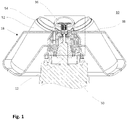
- Fig. 1 shows a schematic representation of a vertical section of a generally designated by the reference numeral 10 centrifuge.
- the substructure is not shown, it is only schematically indicated the upper portion of the engine.
- Fig. 2 to Fig. 7 Cutouts off Fig. 1 reproduced, which contain the essential elements of the invention.
- the centrifuge 10 comprises a cylindrical drive shaft 12 and a arranged on the drive shaft 12 and rotatably connected to the drive shaft 12 adapter 20.
- a concentrically arranged rotor hub 19 of a rotor 18 is applied on the adapter 20.
- the adapter 20 and the rotor hub 19 are rotatably connected in a conventional manner.
- the rotor 18 includes a quick release 22.
- the adapter 20 can be structurally designed either in unit with the rotor hub 19 or in unit with the drive shaft 12 and accordingly adapt either the drive shaft 12 or the rotor hub 19.
- the adapter 20 is optional.
- the drive shaft 12 may be formed for direct reception of the rotor hub 19.
- a projection 13 connects, which consists of a cylindrical portion 13 a and an end portion 13 b.
- the cylindrical portion 13 a is provided with a smaller diameter than the drive shaft 12.
- Drive shaft 12 and projection 13 are integrally formed of the same material.
- the end portion 13b connects.
- the end region 13b consists of a closure ball 14a arranged at its free end and a concave transition region 14b, which is arranged between the closure ball 14a and the cylindrical region 13a of the projection 13.
- the adapter 20 On the drive shaft 12, the adapter 20 is applied.
- the adapter 20 supports it on the shoulder 12a, which is formed around the neck 13 at the free end of the drive shaft 12 around, and has an outer profile, which is structured as follows.
- a pedestal portion 20a is disposed thereon is followed by an upwardly tapering receiving cone 20b, which in turn is followed by a cylindrical portion 20c.
- a bore 20d extends through the adapter 20.
- the bore 20d and thus the adapter 20 have an inner profile which is substantially adapted to the drive shaft 12, wherein the inner profile of the adapter 20 in the base region 20a and in the region of the receiving cone 20b completely the drive shaft 12th while being spaced from the drive shaft 12 in the area of the cylindrical portion 20c which surrounds the concave transition portion 14b below the shutter ball 14a.
- the rotor 18 has a rotor hub 19, the inner profile of which is complementary in the voltage applied to the outer profile of the adapter 20 areas substantially to this outer profile and superimposed on the adapter 20 in the conically shaped portion 20b.
- the inner profile of the rotor hub 19 extends beyond the vertex of the outer profile of the adapter 20 and then passes into a rotor central region 15, which is formed integrally with the rotor hub 19.
- the rotor central region 15 has an underside which, starting from the vertex of the inner profile of the rotor hub 19, proceeds obliquely downwards in the direction of the central axis 11 up to the level of the transition from the closure ball 14a into the transition region 14b and forms an opening 24 in the center of the rotor central region 15 which engages the closure ball 14a.
- the opening 24 is dimensioned so that the closure ball 14a can engage with minimal play in it, and has an upwardly in diameter-spreading opening wall 26, whose lower end is formed to a closing contour / control surface 28 and the upper end in a paragraph 17a perpendicular to the central axis 11 passes.
- the rotor central region 15 Above the shoulder 17a, the rotor central region 15 has a concentric, in cross-section on both sides rectangular profiled wall piece 17 which projects through an opening 40 in the horizontal housing wall 38 and its inner and outer sides are aligned parallel to the central axis 11.
- the quick-release closure 22 is inserted in a pass-fitting manner, which comprises a handle 36, a housing 23, an elongate connecting element 35, compression springs 33 and a plurality of locking springs 32 guided in a guide tube.
- the handle 36 is against the compression spring 33 relative to the housing upwardly in an unlocking and removal direction 16, parallel to the central axis 11 slidably.
- the connecting element 35 has a shoulder 35 a, against which the compression spring 33 rests below.
- the housing 23 extends tubular upwards and also has a shoulder 23a, on which the compression spring 33 abuts the top.
- the shutter springs 32 are power transmission elements which are mounted on the drive shaft 12 facing the end of the connecting element 35 on a connecting ring 35b and which in turn at the drive shaft 12 end facing locking elements 30 have.
- the shutter springs 32 and the locking elements 30 are integrally formed.
- compression spring 33 is provided which exerts pressure on the drive unit 12 formed on the connecting element 35, guide tube and locking springs 32 with locking elements 30 unit.
- the locking springs 32 abut with the blocking elements 30 on the closure ball 14a engaging in the rotor 18 through the opening 24 such that the blocking elements 30 clamp between the closing contour 28 and the closure ball 14a.
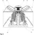
- Fig. 4 For example, the inner portion of the rotor 18, the quick-release fastener 22, and the locking ball 14a are shown schematically in the state where they are located when the rotor 18 is seated on the drive shaft 12 before locking.
- the outer circumference of the closure ball 14a at its widest point 13c is dimensioned so that it can pass through the opening 24 with minimal play. Due to the pressure exerted by the compression springs 33 in the direction of the drive shaft 12, the locking elements 30 provided at the ends of the closure springs 32 abut against a closing contour 28 with their sides facing away from the axis of the drive shaft 12.
- the closure ball 14a engages through the opening 24 and displaces the blocking elements 30 both axially in the removal direction 16 and laterally. Due to the resilient design of the closure springs 32, the blocking elements 30 slide along the surface of the closure ball 14a again approximately back to the position in which they were before the engagement of the closure ball 14a.
- the blocking elements 30 then abut with their support surface 30b against the closing contour 28 and with their bearing surface 30a facing the center axis 11 against the closure ball 14a.
- the locking elements 30 wedged between the closure ball 14a and closing contour 28 and fix the rotor 18 relative to the drive shaft 12.
- the wedging action of the locking elements 30 increases between Locking ball 14a and closing contour 28 still.
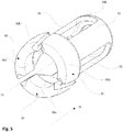
- Fig. 5 the arrangement of the shutter springs 32 and locking elements 30 is shown in perspective.
- a connecting ring 35b which runs concentrically around the central axis 11 on the end of the connecting element 35, not shown here, on the drive shaft 12.
- Integral and integral with the connecting ring 35b three shutter springs 32 are arranged at its circumference at regular intervals to each other, at the ends - facing the viewer - each having a blocking element 30 is provided.
- the locking elements 30 are initially displaced both axially in the removal direction 16 and laterally when the rotor 18 is placed on the closure ball 14a, which is not shown here for the sake of clarity.
- the blocking elements 30 After passing through the closure ball 14a, the blocking elements 30 are essentially brought back into their original position by the closure springs 32. The blocking elements 30 are then in contact with the bearing surface 30a facing the center axis 11 on the closure ball 14a and with its support surface 30b on the control surface 28 of the rotor hub 19, likewise not shown here.
- FIGS. 6 and 7 the operation of the quick release 22 is illustrated again.
- the quick release 22 in Fig. 6 when placed on the drive shaft 12 and on the adapter 20 and shown in FIG Fig. 7 in the fully locked state.
- the Figures 6a and 6b or 7a and 7b each show a section of Fig. 6 respectively.
- Fig. 7 but divided into two partial views (6a and 7a on the rotor side, 6b and 7b on the shaft side).
- the rotor hub 19 is arranged concentrically on the adapter 20.
- the adapter 20 is arranged on the drive shaft 12 and rotatably connected to the drive shaft 12.
- adapter 20 and drive shaft 12 are shown here as a functional unit, so that only the rotor side of the adapter 20 projecting end portion 13 b with the closure ball 14 b can be seen from the drive shaft.
- the closure ball 14b engages through the opening 24 in the rotor hub 19 in the rotor central region 15.
- the wall piece 17 is arranged, in which the quick release 22 is inserted and fixedly connected to the wall piece by a screw, not shown here.
- the handle 36 engages in the removal direction 16 above the rotor 18, the housing 23.
- projections - paragraph 23a - at the handle 36 facing the end of the housing 23 and engaging in the housing 23 end of the connecting element 35 - paragraph 35a - is a lifting of the handle 36 prevented from the housing 23.
- the compression spring 33 is interposed between the handle 36 and the housing 23, the compression spring 33 is interposed.
Landscapes
- Centrifugal Separators (AREA)
Description
- Die Erfindung betrifft eine Zentrifuge gemäß der im Oberbegriff des Patentanspruches 1 angegebenen Art.
- Es sind bereits Zentrifugen mit abnehmbarem Rotor bekannt, die eine Einrichtung zur axialen Verriegelung des Rotors auf der Antriebswelle aufweisen und bei denen zur Verriegelung keine aufwendige Montage und kein spezielles Werkzeug erforderlich sind. Zum Beispiel wird in der
DE 695 14 988 T2 eine Zentrifuge vorgeschlagen, bei der der Rotor beim Aufsetzen automatisch in eine Verriegelungsposition gebracht wird. Hierbei greift ein federbeaufschlagter Riegel in eine Aussparung in der Antriebswelle ein und gewährleistet dadurch eine axiale Feststellung des Rotors. Allerdings bestehen hier die Nachteile, dass bei dieser Lösung die Antriebswelle zu einem nicht unbeträchtlichen Teil in den Rotor eindringen muss, um genügend Angriffsfläche für den Verriegelungsmechanismus zu bieten, und dass die Verriegelung unterhalb des Rotors stattfindet. Dadurch ist ein größerer Platzbedarf erforderlich. Zudem wird die Antriebswelle durch die Anordnung eines Teils des Verriegelungsmechanismus in der Antriebswelle geschwächt. Die Drehzahl und/oder Haltbarkeit derartiger Ausführungen ist daher begrenzt. - Aus der
DE 20 2010 014 803 U1 ist eine Zentrifuge bekannt. Diese weist eine Rotorlagerung mit einem Verriegelungssystem auf, beim dem der Rotor auf der Antriebswelle fixiert wird. Das Verriegelungssystem umfasst sich senkrecht zu der Drehachse erstreckende Achsen und zwischen einer Verriegelungsstellung und einer Entriegelungsstellung um die Achsen schwenkbare Verriegelungshebel. Die Verriegelungshebel greifen in der Verriegelungsstellung in eine Ringnut in der Antriebswelle ein und fixieren den Rotor auf der Welle axial. Die Verriegelungshebel sind drehzahlabhängig selbsttätig aus der Entriegelungsstellung in die Verriegelungsstellung überführbar. Bei ca. 600 RPM wird bei Laborzentrifugen oftmals die erste Resonanz durchlaufen. Die gattungsgemäße Zentrifuge kann jedoch bei diesen Drehzahlen keine nennenswerte axiale Haltekraft aufbringen. - Die
WO 2011/054906 A1 offenbart eine Zentrifuge mit einem über einen Verriegelungsmechanismus mit einer Antriebswelle verbindbaren Rotor. Der Verriegelungsmechanismus weist dabei um parallel zur Antriebsachse verlaufende Achsen schwenkbare Klinken auf, die eine derartige Masseverteilung aufweisen, dass diese drehzahlabhängig in der Verriegelungsposition gehalten werden. Die Klinken greifen dabei in eine Ringnut der Antriebswelle ein. - Die
US 2008/0146429 A1 weist lediglich ein Sperrelement auf, das durch eine Handhabe senkrecht zur Antriebswelle aus einer Entriegelungsposition in eine Verriegelungsposition bewegt wird. - Aus der
JP 164 040 A - Weitere Zentrifugen mit Schnellverschlüssen sind aus der
JP 2001/205136 A WO 83/04379 A - Aufgabe der vorliegenden Erfindung besteht darin, unter Vermeidung der genannten Nachteile eine Zentrifuge mit einem abnehmbaren Rotor zu schaffen, die einen einfacheren und sicheren Schnellverschluss aufweist, der vor allem auch drehzahlunabhängig ist. Insbesondere soll der Verriegelungsmechanismus im Bereich des Rotors weniger Platz für die Verriegelung erfordern.
- Diese Aufgabe wird durch die kennzeichnenden Merkmale des Patentanspruches 1 in Verbindung mit seinen Oberbegriffsmerkmalen gelöst.
- Die Unteransprüche bilden vorteilhafte Weiterbildungen der Erfindung.
- Der Erfindung liegt die Erkenntnis zugrunde, dass es möglich ist, eine sichere axiale Feststellung in Entnahmerichtung von Rotor und Antriebswelle beim Aufsetzen des Rotors auf die Antriebswelle durch eine Verschlusseinrichtung zu gewährleisten, bei der die Antriebswelle mit einem verbreiterten Bereich eine Rotoröffnung durchgreift und eine Verschließeinrichtung zwischen Rotor und verbreiterten Bereich die Öffnung so blockiert, dass der Rotor zur Antriebswelle in Entnahmerichtung festgelegt ist. Auf einfache Weise ist dadurch der Rotor sicher auf der Antriebswelle angeordnet und auch bei hohen Drehzahlen und der damit einhergehenden elastischen Verformung von Bauteilen der Zentrifuge sicher und mit einfach herzustellenden Mitteln in der Zentrifuge angeordnet.
- Nach der Erfindung weist die Zentrifuge eine Antriebswelle mit einem Endbereich auf, welcher sich zum restlichen Bereich der Antriebswelle hin verjüngt, wobei die Verjüngung graduell oder sprunghaft sein kann, sowie einen auf der Antriebswelle gelagerten, axial in eine Entnahmerichtung abnehmbaren Rotor, ferner ein Lager für den Rotor, welches mit der Antriebswelle verbunden ist und den Rotor zumindest entgegen der Entnahmerichtung festlegt, des Weiteren einen in den Rotor integrierten Schnellverschluss, mittels dessen die Antriebswelle und der Rotor in Entnahmerichtung festgelegt sind, und schließlich eine Öffnung im Rotor, durch die die Antriebswelle mit dem Endbereich greift, und die durch eine Öffnungswand begrenzt ist. Dabei sind zur Fixierung des Rotors relativ zur Antriebswelle rotorseitig Sperrelemente vorgesehen, die jeweils den Endbereich teilweise umgreifen. In Entnahmerichtung liegen die Sperrelemente bereichsweise an dem Endbereich an und entgegen der Entnahmerichtung an der Öffnungswand. Dabei ist der durch die Sperrelemente gebildete Außenumfang größer als der Innenumfang der Öffnung. Dadurch entsteht eine Keilwirkung, die sich noch verstärkt, sobald auf den sich drehenden Rotor eine Kraft in Entnahmerichtung zu wirken beginnt. Der Endbereich weist einen verbreiterten Bereich auf, der sich zu einem restlichen Bereich der Antriebswelle hin verjüngt. Der Schnellverschluss ist mit Kraftübertragungselementen versehen, welche die Sperrelemente mit einer Handhabe verbinden, und dass die Verriegelung und/oder die Entriegelung des Schnellverschlusses jeweils durch eine Bewegung der Handhabe und der Kraftübertragungselemente in eine Richtung parallel zur Antriebswelle erfolgen. Hierrüber können Verriegelung und Entriegelung direkt und besonders genau gesteuert werden. Zudem können dadurch einerseits das Aufsetzen des Rotors auf die Antriebswelle mit der Verriegelung und andererseits die Entnahme des Rotors mit der Entriegelung gut kombiniert werden. Die erfindungsgemäße Lösung ist gegenüber der gattungsgemäßen Ausführung weniger störanfällig. Die Antriebswelle und der Rotor können einfacher ausgeführt werden. Es müssen weniger Teile aufwändig montiert werden. Der Rotor ist unabhängig von der Drehzahl immer sicher fixiert.
- Diese Anordnung hat den Vorteil, dass nur ein vergleichsweise kleiner Endbereich der Antriebswelle zur axialen Feststellung von Rotor und Antriebswelle verwendet werden muss und dass auf einen Verriegelungsmechanismus verzichtet werden kann, der zur Fixierung eine laterale Kraft ausübt und bei dem ein gewisser Längenabschnitt der Antriebswelle erforderlich ist. Somit wird ein geringerer Platzbedarf erreicht und eine Schwächung der Antriebswelle vermieden.
- Bei einer bevorzugten Ausführung sind die Sperrelemente über zumindest eine Feder federelastisch bewegbar und in Richtung der Antriebswelle vorgespannt. Durch diese Federbeaufschlagung ist gewährleistet, dass die Sperrelemente beim Aufsetzen des Rotors entgegen der durch die Öffnung eingreifenden Antriebswelle leicht in ihre vorgesehene Position gelangen, den Endbereich der Antriebswelle umfassen und somit den Rotor und die Antriebswelle axial fixieren.
- Besonders gut kann einer ungewollten Verdrängung der Sperrelemente aus ihrer vorgesehenen Position entgegengewirkt werden, wenn die Sperrelemente durch die Feder elastisch so auslenkbar sind, dass der Endbereich in seiner breitesten Stelle in Bezug auf die Mittelachse der Antriebswelle passierbar ist.
- Vorteilhaft ist es ferner, die Feder zwischen Handhabe und Sperrelemente einzubringen, weil sich dadurch die Konstruktion des Schnellverschlusses deutlich vereinfachen lässt.
- Eine weitere konstruktive Vereinfachung lässt sich dadurch erzielen, dass die Kraftübertragungselemente die Feder bilden.
- In einer besonders bevorzugten Ausführung der Erfindung sind die Kraftübertragungselemente federbelastet. Dies gewährleistet, dass die Sperrelemente, wenn sie beim Aufsetzen des Rotors von dem durch die Öffnung eingreifenden Endbereich der Antriebswelle zunächst aus ihrer Position verdrängt werden, schließlich in Aufsetzrichtung am Endbereich vorbeigreifen, sich an diesen anlegen und zuverlässig ihre Sperrwirkung erfüllen.
- Eine noch zuverlässigere Funktion der Sperrelemente kann dadurch erreicht werden, dass sie in ihrer Form der Form des Endbereichs der Antriebswelle zumindest bereichsweise angepasst sind. Diese Ausgestaltung der Sperrelemente ermöglicht einen besseren Formschluss zwischen dem Endbereich der Antriebswelle und dem Schnellverschluss sowie zwischen dem Schnellverschluss und der Öffnungswand und reduziert die Materialbelastung, insbesondere die Belastung der Sperrelemente.
- Günstig ist es, wenn der Endbereich der Antriebswelle kugelförmig ausgebildet ist und insbesondere dabei im Übergangsbereich von der Kugel zur Antriebswelle konkav verrundet ist, da es dadurch den Sperrelementen erleichtert wird, den Endbereich der Antriebswelle zu umfassen und sich an ihn anzulegen, und da darüber hinaus die Herstellung eines Formschlusses zwischen dem Endbereich der Antriebswelle und dem Schnellverschluss sowie zwischen dem Schnellverschluss und der Öffnungswand noch einmal vereinfacht wird.
- Gemäß einem Aspekt der Erfindung weist die Öffnungswand eine Steuerfläche für die Sperrelemente auf, die bei Einbringen des Rotors in die Verriegelungsposition des Schnellverschlusses durch Bewegen entgegen der Entnahmerichtung die Sperrelemente in Richtung Antriebswelle bewegt und in Verriegelungsposition gegen die Antriebswelle drückt. Dies verbessert die Steuerbarkeit der Sperrelemente weiter, da diese gegen einen minimalen Widerstand leicht in ihre Sperrposition gleiten.
- Eine zusätzliche Verbesserung der Stabilität der axialen Feststellung von Rotor und Antriebswelle kann dadurch erzielt werden, dass die Steuerfläche so ausgebildet ist, dass in der Verriegelungsposition die Sperrelemente bereichsweise an der dem Endbereich zugewandten Seite am Endbereich anliegen und auf der dem Endbereich abgewandten Seite an der Steuerfläche anliegen. So entsteht ein besserer Formschluss zwischen dem Endbereich der Antriebswelle und dem Schnellverschluss sowie zwischen dem Schnellverschluss und der Öffnungswand.
- Als besonders vorteilhaft hat es sich erwiesen, wenn die Steuerfläche bei einer Bewegung in Entnahmerichtung, also bei Öffnen des Schnellverschlusses, ein Auslenken der Sperrelemente ermöglicht. Durch diese Ausbildung kann der Schnellverschluss mit relativ geringem Kraftaufwand bequem entriegelt werden.
- Gemäß einem weiteren Aspekt der Erfindung sind die Entriegelungsrichtung und die Entnahmerichtung gleich. Dies bietet eine weitere Möglichkeit, den Aufbau des Schnellverschlusses und des Rotors einfacher und kompakter zu gestalten.
- Sehr einfach kann die Entnahme des Rotors dadurch gestaltet werden, dass die Entriegelung des Schnellverschlusses und die Entnahme des Rotors mechanisch miteinander gekoppelt sind, weil dann nur eine einzelne Bewegung erforderlich ist, um gleichzeitig den Verschluss zu lösen und den Rotor aus der Zentrifuge zu entnehmen.
- Eine besonders sichere Verriegelung kann dadurch erreicht werden, dass zumindest zwei, vorzugsweise drei Sperrelemente vorgesehen sind, die in gleichmäßigen Abstand zueinander angeordnet sind.
- Wenn sich die Sperrelemente bereichsweise in die Öffnung erstrecken, wird ein noch besserer Formschluss zwischen dem Endbereich der Antriebswelle und dem Schnellverschluss sowie zwischen dem Schnellverschluss und der Öffnungswand erzielt und damit auch die Verriegelung verbessert.
- In einer besonders bevorzugten Ausführung der Erfindung verläuft eine Schwenkachse der Sperrelemente senkrecht zur Mittelachse der Antriebswelle und die Federn verlaufen in der nicht ausgelenkten Stellung von der Schwenkachse, bezogen auf die Mittelachse, nach unten, insbesondere parallel zur Mittelachse. Diese Anordnung bewirkt, dass die Sperrelemente beim Aufsetzen und beim Abnehmen des Rotors leicht am Endbereich der Antriebswelle, insbesondere an der Verschlusskugel, entlanggleiten und dass dadurch eine leichte Ver- bzw. Entriegelung ermöglicht wird.
- Gemäß einem Aspekt der Erfindung sind die Feder und das Sperrelement einstückig und materialeinheitlich ausgebildet und umgreifen bereichsweise den Endbereich. Dies senkt die Herstellungskosten und verbessert die Sperrwirkung.
- Günstig ist es, wenn die Steuerfläche zumindest über eine Höhe der Mittelachse konzentrisch zu dieser verläuft und wenn die Sperrelemente zumindest über eine Höhe der Mittelachse konzentrisch zu dieser verlaufen. Durch diese konzentrische Anordnung wird die Steuerung der Sperrelemente noch sicherer gestaltet und ein Verkanten oder Verklemmen der Speerelemente, insbesondere beim Aufsetzen des Rotors, weitestgehend verhindert.
- Vorteilhaft ist es ferner, wenn die Handhabe, die Kraftübertragungselemente, die Federn und die Sperrelemente in Reihe geschaltet sind. So können die Entriegelung und die Verriegelung mit minimalem Kraftaufwand mit einer Bewegung vorgenommen werden.
- Bei einer bevorzugten Ausführung sind die Federn und die Sperrelemente in der Entriegelungsstellung und in der Verriegelungsstellung im Wesentlichen parallel zu der Mittelachse ausgerichtet und während der Entriegelung zeitweise schräg zur Mittelachse. Dadurch wird die Klemmkraft der Sperrelemente erhöht und die Verriegelungswirkung des Schnellverschlusses deutlich verbessert.
- Weitere Vorteile, Merkmale und Anwendungsmöglichkeiten der vorliegenden Erfindung ergeben sich aus der nachfolgenden Beschreibung in Verbindung mit den in den Zeichnungen dargestellten Ausführungsbeispielen.
- In der Beschreibung, in den Ansprüchen und in der Zeichnung werden die in der unten aufgeführten Liste der Bezugszeichen verwendeten Begriffe und zugeordneten Bezugszeichen verwendet. In der Zeichnung bedeutet:
- Fig. 1
- eine Schnittansicht entlang der Mittelachse der Zentrifuge nach der Erfindung;
- Fig. 2
- eine vergrößerte Detailansicht des in
Fig. 1 markierten Ausschnitts; - Fig. 3
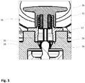
- eine vergrößerte Detailansicht des in
Fig. 2 markierten Ausschnitts; - Fig. 4
- eine Schnittansicht des Schnellverschlusses im entriegelten Zustand;
- Fig. 5
- eine perspektivische Detailansicht der Baueinheit aus Verschlussfedern und Sperrelementen;
- Fig. 6
- einen Ausschnitt aus einem Querschnitt entlang der Mittelachse der Zentrifuge von
Fig. 1 mit Schnellverschluss im entriegelten Zustand, aber noch mit auf der Welle aufgesetzten Rotor; - Fig. 6a,
- einen rotorseitig Ausschnitt von
Fig. 6 im von der Antriebswelle abgenommenen Zustand; - Fig. 6b
- einen wellenseitig Ausschnitt von
Fig. 6 , bei dem der Rotor entfernt ist; - Fig. 7
- einen Ausschnitt aus einem Querschnitt entlang der Mittelachse der Zentrifuge von
Fig. 1 mit Schnellverschluss im verriegelten Zustand von Rotor und Antriebswelle; - Fig. 7a
- einen rotorseitigen Ausschnitt von
Fig. 7 im von der Antriebswelle abgenommenen Zustand, und - Fig. 7b
- einen wellenseitigen Ausschnitt von
Fig. 7 bei dem der Rotor entfernt ist. -
Fig. 1 zeigt in schematischer Darstellung einen vertikalen Schnitt einer insgesamt mit der Bezugsziffer 10 bezeichneten Zentrifuge. Der Übersichtlichkeit halber ist die Unterkonstruktion nicht dargestellt, es wird nur der obere Bereich des Motors schematisch angedeutet. Zur deutlicheren Darstellung sind inFig. 2 bis Fig. 7 Ausschnitte ausFig. 1 wiedergegeben, die die für die Erfindung wesentlichen Elemente beinhalten. - Nach dem in
Fig. 1 bis 7 dargestellten Beispiel umfasst die Zentrifuge 10 eine zylindrische Antriebswelle 12 und einen auf der Antriebswelle 12 angeordneten und mit der Antriebswelle 12 drehfest verbundenen Adapter 20. Auf dem Adapter 20 ist eine konzentrisch angeordnete Rotornabe 19 eines Rotors 18 aufgebracht. Der Adapter 20 und die Rotornabe 19 sind drehfest in herkömmlicher Weise verbunden. Der Rotor 18 umfasst einen Schnellverschluss 22. - Der Adapter 20 kann konstruktiv wahlweise in Einheit mit der Rotornabe 19 oder in Einheit mit der Antriebswelle 12 ausgelegt werden und dementsprechend entweder die Antriebswelle 12 oder die Rotornabe 19 adaptieren. Im Übrigen ist der Adapter 20 optional. Alternativ kann auch die Antriebswelle 12 zur unmittelbaren Aufnahme der Rotornabe 19 ausgebildet sein.
- An das freie Ende der zylindrischen Antriebswelle 12 schließt sich ein Ansatz 13 an, der aus einem zylindrischen Bereich 13a und einem Endbereich 13b besteht. Der zylindrische Bereich 13a ist mit einem geringeren Durchmesser als die Antriebswelle 12 versehen. Antriebswelle 12 und Ansatz 13 sind einstückig und materialeinheitlich ausgebildet. An den zylindrischen Bereich 13a des Ansatzes 13 schließt sich der Endbereich 13b an. Der Endbereich 13b besteht aus einer an seinem freien Ende angeordneten Verschlusskugel 14a und einem konkaven Übergangsbereich 14b, der zwischen Verschlusskugel 14a und zylindrischen Bereich 13a des Ansatzes 13 angeordnet ist.
- Auf der Antriebswelle 12 ist der Adapter 20 aufgebracht. Der Adapter 20 lagert dabei auf dem Absatz 12a, welcher am freien Ende der Antriebswelle 12 um den Ansatz 13 herum ausgebildet ist, und weist ein Außenprofil auf, das wie folgt gegliedert ist. Unten ist ein Sockelbereich 20a angeordnet, daran schließt sich ein sich nach oben verjüngender Aufnahmekonus 20b an, an welchen sich wiederum ein zylindrischer Abschnitt 20c anschließt. Eine Bohrung 20d durchgreift den Adapter 20. Die Bohrung 20d und somit der Adapter 20 weisen ein Innenprofil auf, das im Wesentlichen an die Antriebswelle 12 angepasst ist, wobei das Innenprofil des Adapters 20 im Sockelbereich 20a und im Bereich des Aufnahmekonus 20b vollständig der Antriebswelle 12 angepasst ist, während es in dem Bereich des zylindrischen Abschnitts 20c, der den konkav ausgebildeten Übergangsbereich 14b unterhalb der Verschlusskugel 14a umgibt, von der Antriebswelle 12 beabstandet ist.
- Der Rotor 18 weist eine Rotornabe 19 auf, deren Innenprofil in den am Außenprofil des Adapters 20 anliegenden Bereichen im Wesentlichen zu diesem Außenprofil komplementär ist und in dem konisch ausgebildeten Bereich 20b auf dem Adapter 20 lagert. Dabei erstreckt sich das Innenprofil der Rotornabe 19 über den Scheitelpunkt des Außenprofils des Adapters 20 hinaus und geht dann in einen Rotorzentralbereich 15 über, welcher einstückig mit der Rotornabe 19 ausgebildet ist. Der Rotorzentralbereich 15 weist eine Unterseite auf, die vom Scheitelpunkt des Innenprofils der Rotornabe 19 ausgehend in Richtung Mittelachse 11 schräg nach unten bis auf Höhe des Übergangs von der Verschlusskugel 14a in den Übergangsbereich 14b verläuft und im Zentrum des Rotorzentralbereichs 15 eine Öffnung 24 ausbildet, in die die Verschlusskugel 14a eingreift. Die Öffnung 24 ist so dimensioniert, dass die Verschlusskugel 14a mit minimalem Spiel in sie eingreifen kann, und weist eine sich nach oben hin im Durchmesser verbreitende Öffnungswand 26 auf, deren unteres Ende zu einer Schließkontur/Steuerfläche 28 ausgebildet ist und deren oberes Ende in einen lotrecht zur Mittelachse 11 liegenden Absatz 17a übergeht. Oberhalb des Absatzes 17a weist der Rotorzentralbereich 15 ein konzentrisches, oben im Querschnitt beidseitig rechteckig profiliertes Wandstück 17 auf, das durch eine Öffnung 40 in der horizontalen Gehäusewand 38 hindurchragt und dessen Innen- und Außenseite parallel zur Mittelachse 11 ausgerichtet sind.
- An der Innenseite des Wandstücks 17 ist passförmig der Schnellverschluss 22 eingesetzt, der eine Handhabe 36, ein Gehäuse 23, ein in einer Führungsröhre geführtes längliches Verbindungselement 35, Druckfedern 33 und eine Mehrzahl von Verschlussfedern 32 umfasst. Die Handhabe 36 ist gegen die Druckfeder 33 relativ zum Gehäuse nach oben in eine Entriegelungsrichtung und Entnahmerichtung 16, parallel zur Mittelachse 11 verschiebbar. Hierfür das Verbindungselement 35 einen Absatz 35a auf, an dem die Druckfeder 33 unten anliegt. Das Gehäuse 23 erstreckt sich rohrförmig nach oben und weist ebenfalls einen Absatz 23a, an dem die Druckfeder 33 oben anliegt.
- Die Verschlussfedern 32 sind Kraftübertragungselemente, die am der Antriebswelle 12 zugewandten Ende des Verbindungselements 35 an einem Verbindungsring 35b angebracht sind und die ihrerseits an den der Antriebswelle 12 zugewandten Ende Sperrelemente 30 aufweisen. Dabei sind die Verschlussfedern 32 und die Sperrelemente 30 einstückig ausgebildet. Zwischen der Führungsröhre des Verbindungselements 35 und der Innenwand des Gehäuses 23 ist die parallel zur Mittelachse 11 ausgerichtete Druckfeder 33 vorgesehen, die auf die aus Verbindungselement 35, Führungsröhre und Verschlussfedern 32 mit Sperrelementen 30 gebildete Einheit Druck in Richtung Antriebswelle 12 ausübt. Die Verschlussfedern 32 liegen mit den Sperrelementen 30 so an der durch die Öffnung 24 in den Rotor 18 eingreifenden Verschlusskugel 14a an, dass sich die Sperrelemente 30 zwischen die Schließkontur 28 und die Verschlusskugel 14a klemmen.
- In
Fig. 4 sind der Innenbereich des Rotors 18, der Schnellverschluss 22 und die Verschlusskugel 14a schematisch in dem Zustand dargestellt, in dem sie sich beim Aufsetzen des Rotors 18 auf die Antriebswelle 12 vor dem Verriegeln befinden. Der Außenumfang der Verschlusskugel 14a an ihrer breitesten Stelle 13c ist so bemessen, dass sie mit minimalem Spiel die Öffnung 24 passieren kann. Auf Grund des Drucks, der von den Druckfedern 33 in Richtung Antriebswelle 12 ausgeübt wird, liegen die an den Enden der Verschlussfedern 32 vorgesehenen Sperrelemente 30 mit ihren von der Achse der Antriebswelle 12 abgewandten Seiten an einer Schließkontur 28 an. - Wird nun der Rotor 18 heruntergedrückt, greift die Verschlusskugel 14a durch die Öffnung 24 und verdrängt dabei zuerst die Sperrelemente 30 sowohl axial in Entnahmerichtung 16 als auch lateral. Auf Grund der federelastischen Ausbildung der Verschlussfedern 32 gleiten die Sperrelemente 30 entlang der Oberfläche der Verschlusskugel 14a wieder annähernd zurück in die Position, in der sie sich vor dem Eingreifen der Verschlusskugel 14a befanden.
- Die Sperrelemente 30 liegen daraufhin mit ihrer Stützfläche 30b an der Schließkontur 28 und mit ihren der Mittelachse 11 zugewandten Lagerfläche 30a an der Verschlusskugel 14a an. Dabei verkeilen sich die Sperrelemente 30 zwischen Verschlusskugel 14a und Schließkontur 28 und fixieren den Rotor 18 relativ zur Antriebswelle 12. Sobald der Rotor 18 in Betrieb ist und auf Grund der Rotation Kräfte in Entnahmerichtung 16 auf ihn einwirken, erhöht sich die Keilwirkung der Sperrelemente 30 zwischen Verschlusskugel 14a und Schließkontur 28 noch.
- Kommt der Rotor 18 nach dem Ende der Zentrifugation zum Stillstand, wirken keine Kräfte in Entnahmerichtung 16 mehr auf ihn. Dadurch verringert sich die Keilwirkung der Sperrelemente 30 beträchtlich, so dass die Sperrelemente 30 durch Anheben des Verschlusskopfs 36 leicht aus ihrer Position zwischen Verschlusskugel 14a und Schließkontur 28 entfernt werden können. Daraufhin kann der Rotor 18 wieder vom Adapter 20 abgehoben werden.
- In
Fig. 5 ist die Anordnung der Verschlussfedern 32 und Sperrelemente 30 perspektivisch dargestellt. An der vom Betrachter abgewandten Seite befindet sich ein Verbindungsring 35b, der am der Antriebswelle 12 zugewandten Ende des hier nicht dargestellten Verbindungselements 35 konzentrisch um die Mittelachse 11 verläuft. Einstückig und materialeinheitlich mit dem Verbindungsring 35b sind an dessen Umfang in gleichmäßigen Abständen zueinander drei Verschlussfedern 32 angeordnet, an deren Enden - in Richtung des Betrachters weisend - jeweils ein Sperrelement 30 vorgesehen ist. Wie bereits in denFig. 3 und4 erläutert, werden die Sperrelemente 30 beim Aufsetzen des Rotors 18 zunächst von der hier der Übersichtlichkeit halber nicht gezeigten Verschlusskugel 14a sowohl axial in Entnahmerichtung 16 als auch lateral verdrängt. Nach dem Passieren der Verschlusskugel 14a werden die Sperrelemente 30 von den Verschlussfedern 32 im Wesentlichen wieder in ihre ursprüngliche Position gebracht. Die Sperrelemente 30 liegen dann mit ihren zur Mittelachse 11 weisenden Lagerfläche 30a an der Verschlusskugel 14a an und mit ihrer Stützfläche 30b an der hier ebenfalls nicht dargestellten Steuerfläche 28 der Rotornabe 19. - In den
Figuren 6 und7 wird die Funktionsweise des Schnellverschlusses 22 nochmals verdeutlicht. Dabei ist der Schnellverschluss 22 inFig. 6 beim Aufsetzen auf die Antriebswelle 12 bzw. auf den Adapter 20 dargestellt und inFig. 7 im vollständig eingerasteten Zustand. DieFiguren 6a und 6b bzw. 7a und 7b zeigen jeweils einen Ausschnitt vonFig. 6 bzw.Fig. 7 , jedoch aufgeteilt in jeweils zwei Teilansichten (6a und 7a rotorseitig, 6b und 7b wellenseitig). - Wie bereits in den
Figuren 1 bis 4 dargestellt ist die Rotornabe 19 auf dem Adapter 20 konzentrisch angeordnet. Der Adapter 20 ist auf der Antriebswelle 12 angeordnet und mit der Antriebswelle 12 drehfest verbunden. Der Einfachheit halber werden Adapter 20 und Antriebswelle 12 hier als funktionelle Einheit dargestellt, so dass von der Antriebswelle 12 nur der rotorseitig aus dem Adapter 20 herausragende Endbereich 13b mit der Verschlusskugel 14b erkennbar ist. Die Verschlusskugel 14b greift durch die Öffnung 24 in der Rotornabe 19 in den Rotorzentralbereich 15 ein. In Entnahmerichtung 16 ist oberhalb der Rotornabe 19 konzentrisch zur Mittelachse 11 das Wandstück 17 angeordnet, in das der Schnellverschluss 22 eingesetzt und mit dem Wandstück durch eine hier nicht dargestellte Schraubverbindung fest verbunden ist. - Die Handhabe 36 umgreift in Entnahmerichtung 16 oberhalb des Rotors 18 das Gehäuse 23. Durch Auskragungen - Absatz 23a - am der Handhabe 36 zugewandten Ende des Gehäuses 23 und der in das Gehäuse 23 eingreifenden Ende des Verbindungselements 35 - Absatz 35a - wird ein Abheben der Handhabe 36 vom Gehäuse 23 verhindert. Wie oben erläutert ist zwischen Handhabe 36 und Gehäuse 23 die Druckfeder 33 zwischengeschaltet.
- In
Fig. 6 und den ergänzendenFiguren 6a und 6b ist die Druckfeder 33 zusammengedrückt, so dass die aus Handhabe 36, Verbindungselement 35 und Verschlussfedern 32 mit Sperrelementen 30 gebildete Einheit auf der Mittelachse 11 in Entnahmerichtung 16 verschoben ist. Die Sperrelemente 30 berühren mit ihren freien Enden die Verschlusskugel 14a, liegen jedoch nicht an ihr an und haben noch keine Keilwirkung. - In
Fig. 7 und den ergänzendenFiguren 7a und 7b sind die Druckfedern 33 entspannt, wodurch die aus Handhabe 36, Verbindungselement 35 und Verschlussfedern 32 mit Sperrelementen 30 gebildete Einheit entgegen der Entnahmerichtung 16 verschoben ist, wie bereits im Zusammenhang mitFig. 4 beschrieben. Die Sperrelemente 30 sind nun zwischen Verschlusskugel 14a und Steuerfläche 28 verklemmt und entfalten eine Keilwirkung. -
- 10
- Zentrifuge
- 11
- Mittelachse
- 12
- Antriebswelle
- 12a
- Absatz
- 13
- Ansatz
- 13a
- zylindrischer Bereich
- 13b
- Endbereich
- 13c
- breiteste Stelle
- 14a
- Verschlusskugel
- 14b
- Übergangsbereich
- 15
- Rotorzentralbereich
- 16
- Entnahmerichtung
- 17
- Wandstück
- 17a
- Absatz
- 18
- Rotor
- 19
- Rotornabe
- 20
- Adapter
- 20a
- Sockelbereich
- 20b
- Aufnahmekonus
- 20c
- zylindrischer Abschnitt
- 20d
- Bohrung
- 22
- Schnellverschluss
- 23
- Gehäuse
- 23a
- Absatz des Gehäuses 23 oben
- 24
- Öffnung
- 26
- Öffnungswand
- 28
- Steuerfläche
- 30
- Sperrelemente
- 30a
- Lagerfläche
- 30b
- Stützfläche
- 31
- Schwenkachse
- 32
- Verschlussfedern
- 33
- Druckfeder
- 35
- Verbindungselement
- 35a
- Absatz des Verbindungselements 35
- 35b
- Verbindungsring
- 36
- Handhabe
- 38
- Gehäusewand
- 40
- Öffnung
- 50
- Motor
- 52
- Ausnehmungen für Probenbehälter
- 54
- Probenbehälter
Claims (15)
- Zentrifuge (10), aufweisenda) eine Antriebswelle (12), welche einen Endbereich (13b) aufweist, der sich zur Mittelachse (11) der Antriebswelle (12) hin verjüngt,b) einen auf der Antriebswelle (12) gelagerten, axial in eine Entnahmerichtung (16) abnehmbaren Rotor (18),c) ein Lager (20) für den Rotor (18), das mit der Antriebswelle (12) verbunden ist und den Rotor (18) zumindest entgegen der Entnahmerichtung (16) hält,d) einen in den Rotor (18) integrierten Schnellverschluss (22), mittels dessen die Antriebswelle (12) und der Rotor (18) in Entnahmerichtung (16) fixiert werden,e) eine Öffnung (24) im Rotor (18), durch welche die Antriebswelle (12) mit dem Endbereich (13b) greift, und die durch eine Öffnungswand (26) des Rotors (18) begrenzt ist,wobei, zur Festlegung von Rotor (18) und Antriebswelle (12) rotorseitig mehrere Sperrelemente (30) vorgesehen sind, der Endbereich (13b) einen verbreiterten Bereich aufweist, der sich zu einem restlichen Bereich der Antriebswelle (12) hin verjüngt, der Schnellverschluss (22) Kraftübertragungselemente (32) aufweist, welche die Sperrelemente (30) mit einer Handhabe (36) verbinden, und dass die Verriegelung und/oder die Entriegelung des Schnellverschlusses (22) jeweils durch eine Bewegung der Handhabe (36) und der Kraftübertragungselemente (32) in eine Richtung parallel zur Antriebswelle (12) erfolgen, dadurch gekennzeichnet, dass die Sperrelemente (30) zum Festlegen des Rotors (18) relativ zur Antriebswelle (12) den Endbereich (13b) jeweils zumindest teilweise umgreifen, und die Sperrelemente (30) mit einer in Entnahmerichtung (16) weisenden Lagerfläche (30a) an dem Endbereich (13b) anliegen, die Sperrelemente (30) mit einer entgegen der Entnahmerichtung (16) weisenden Stützfläche (30b) an der Öffnungswand (26) des Rotors (18) anliegen und die Stützfläche der Sperrelemente (30) bei Anliegen einen Außenumfang bilden, der größer als der Innenumfang der Öffnung (24) ist,
- Zentrifuge nach Anspruch 1, dadurch gekennzeichnet, dass die Sperrelemente (28) über zumindest eine Feder (32) federelastisch bewegbar und in Richtung der Antriebswelle (12) vorgespannt sind.
- Zentrifuge nach Anspruch 1 oder 2, dadurch gekennzeichnet, dass die Sperrelemente (30) zum Entriegeln und Verriegeln des Schnellverschlusses (22) durch die Feder (32) elastisch so auslenkbar sind, dass der Endbereich (13b) an seiner breitesten Stelle (13c) in Bezug auf die Mittelachse (11) der Antriebswelle (12) durch die Sperrelemente (30) passierbar ist.
- Zentrifuge nach Anspruch 2 oder 3, dadurch gekennzeichnet, dass die Feder (32) zwischen Handhabe (36) und Sperrelementen (30) angeordnet ist, und/oder dass die Kraftübertragungselemente die Feder (32) bilden.
- Zentrifuge nach einem der Ansprüche 2 bis 4, dadurch gekennzeichnet, dass die Kraftübertragungselemente (32) federbelastet sind, so dass die Sperrelemente (30), wenn sie beim Aufsetzen des Rotors (18) von dem durch die Öffnung (24) eingreifenden Endbereich (13b) der Antriebswelle (12) zunächst aus ihrer Position verdrängt werden, schließlich in Aufsetzrichtung am Endbereich (13b) vorbeigreifen, sich an diesen anlegen und ihre Sperrwirkung erfüllen.
- Zentrifuge nach einem der vorangehenden Ansprüche, dadurch gekennzeichnet, dass die Sperrelemente (30) auf ihrer zur Antriebswelle (12) zugewandten Seite im Hinblick auf die Form des Endbereichs (13b) der Antriebswelle (12) angepasst sind.
- Zentrifuge nach einem der vorangehenden Ansprüche, dadurch gekennzeichnet, dass der Endbereich (13b) der Antriebswelle (12) kugelförmig ausgebildet ist und dass er insbesondere dabei im Übergangsbereich von der Verschlusskugel (14a) zur Antriebswelle (12) konkav verrundet ist.
- Zentrifuge nach einem der vorangehenden Ansprüche, dadurch gekennzeichnet, dass die Öffnungswand (26) eine Steuerfläche (28) für die Sperrelemente (30) aufweist, die bei Einbringen des Rotors (18) durch Bewegen entgegen der Entnahmerichtung (16) in eine Verriegelungsposition des Schnellverschlusses (22) die Sperrelemente (30) in Richtung Antriebswelle (12) bewegt und in die Verriegelungsposition gegen die Antriebswelle (12) drückt, insbesondere ist dabei die Steuerfläche (28) so ausgebildet ist, dass in der Verriegelungsposition die Sperrelemente (30) bereichsweise an der dem Endbereich (13b) zugewandten Seite am Endbereich (13b) anliegen und auf der dem Endbereich (13b) abgewandten Seite an der Steuerfläche (28) anliegen.
- Zentrifuge nach einem der Ansprüche 7 oder 8, dadurch gekennzeichnet, dass die Steuerfläche (28) bei einer Bewegung in Entnahmerichtung (16), also bei Öffnen des Schnellverschlusses (22), ein Auslenken der Sperrelemente (30) ermöglicht.
- Zentrifuge nach einem der vorangehenden Ansprüche, dadurch gekennzeichnet, dass die Entriegelungsrichtung und die Entnahmerichtung (16) gleich sind und/oder dass die Entriegelung des Schnellverschlusses (22) und die Entnahme des Rotors (18) mechanisch miteinander gekoppelt sind.
- Zentrifuge nach einem der vorangehenden Ansprüche, dadurch gekennzeichnet, dass eine Schwenkachse der Sperrelemente (30) senkrecht zur Mittelachse (11) der Antriebswelle (12) verläuft und dass die Federn (32) in der nicht ausgelenkten Stellung von der Schwenkachse bezogen auf die Mittelachse (11) nach unten, insbesondere parallel zur Mittelachse (11), verlaufen.
- Zentrifuge nach einem der vorangehenden Ansprüche, dadurch gekennzeichnet, dass die Feder (32) und das Sperrelement (30) einstückig und materialeinheitlich ausgebildet sind und den Endbereich (13b) bereichsweise umgreifen.
- Zentrifuge nach einem der vorangehenden Ansprüche, dadurch gekennzeichnet, dass die Steuerfläche (28) zumindest über eine Höhe der Mittelachse (11) konzentrisch zu dieser verläuft und dass die Sperrelemente (30) zumindest über eine Höhe der Mittelachse (11) konzentrisch zu dieser verlaufen.
- Zentrifuge nach einem der vorangehenden Ansprüche, dadurch gekennzeichnet, dass die Handhabe (36), die Kraftübertragungselemente, die Federn (32) und die Sperrelemente (30) in Reihe geschaltet sind.
- Zentrifuge nach einem der vorangehenden Ansprüche, dadurch gekennzeichnet, dass die Federn (32) und die Sperrelemente (30) in der Entriegelungsstellung und in der Verriegelungsstellung im Wesentlichen parallel zu der Mittelachse (11) und während der Entriegelung schräg zur Mittelachse (11) ausgerichtet sind.
Applications Claiming Priority (2)
| Application Number | Priority Date | Filing Date | Title |
|---|---|---|---|
| DE102013107681.5A DE102013107681B4 (de) | 2013-07-18 | 2013-07-18 | Zentrifuge |
| PCT/EP2014/064868 WO2015007620A1 (de) | 2013-07-18 | 2014-07-10 | Zentrifuge |
Publications (2)
| Publication Number | Publication Date |
|---|---|
| EP3021974A1 EP3021974A1 (de) | 2016-05-25 |
| EP3021974B1 true EP3021974B1 (de) | 2018-06-27 |
Family
ID=51302696
Family Applications (1)
| Application Number | Title | Priority Date | Filing Date |
|---|---|---|---|
| EP14750321.3A Active EP3021974B1 (de) | 2013-07-18 | 2014-07-10 | Zentrifuge |
Country Status (4)
| Country | Link |
|---|---|
| US (1) | US10300499B2 (de) |
| EP (1) | EP3021974B1 (de) |
| DE (1) | DE102013107681B4 (de) |
| WO (1) | WO2015007620A1 (de) |
Families Citing this family (18)
| Publication number | Priority date | Publication date | Assignee | Title |
|---|---|---|---|---|
| DE102012011531B4 (de) * | 2012-06-08 | 2016-11-10 | Thermo Electron Led Gmbh | Set aus Antriebskopf und Nabe zur lösbaren Verbindung eines Antriebes mit einem Rotor einer Zentrifuge für einen weiten Drehzahlbereich |
| FR3005273A1 (fr) * | 2013-05-02 | 2014-11-07 | Afi Centrifuge | Centrifugeuse de laboratoire comprenant des moyens pour le verrouillage en translation d'un rotor sur un arbre moteur d'entrainement |
| DE102013107681B4 (de) * | 2013-07-18 | 2018-02-08 | Andreas Hettich Gmbh & Co. Kg | Zentrifuge |
| DE102014008219B4 (de) * | 2014-05-28 | 2018-08-02 | Thermo Electron Led Gmbh | Antriebskopf zur lösbaren Verbindung eines Antriebes mit einem Rotor einer Zentrifuge, diesen umfassendes Set und Zentrifuge |
| DE102014112501B4 (de) * | 2014-08-29 | 2017-07-27 | Andreas Hettich Gmbh & Co. Kg | Zentrifuge |
| EP3012027B1 (de) * | 2014-10-21 | 2016-09-21 | Sigma Laborzentrifugen GmbH | Zentrifugalkraftbetätigte kupplungseinrichtung für eine laborzentrifuge |
| US9839253B2 (en) | 2014-12-10 | 2017-12-12 | Nike, Inc. | Last system for braiding footwear |
| US10060057B2 (en) | 2015-05-26 | 2018-08-28 | Nike, Inc. | Braiding machine with non-circular geometry |
| US10280538B2 (en) | 2015-05-26 | 2019-05-07 | Nike, Inc. | Braiding machine and method of forming an article incorporating a moving object |
| US10238176B2 (en) | 2015-05-26 | 2019-03-26 | Nike, Inc. | Braiding machine and method of forming a braided article using such braiding machine |
| US9920462B2 (en) | 2015-08-07 | 2018-03-20 | Nike, Inc. | Braiding machine with multiple rings of spools |
| DE102015113854A1 (de) * | 2015-08-20 | 2017-02-23 | Andreas Hettich Gmbh & Co. Kg | Rotor einer Zentrifuge |
| DE102015113855A1 (de) * | 2015-08-20 | 2017-02-23 | Andreas Hettich Gmbh & Co. Kg | Rotor einer Zentrifuge |
| JP6192860B1 (ja) * | 2016-07-13 | 2017-09-06 | 株式会社久保田製作所 | ロータの取付構造及び遠心分離機 |
| DE102017130787A1 (de) * | 2017-12-20 | 2019-06-27 | Eppendorf Ag | Zentrifugenrotor |
| DE102018114289A1 (de) * | 2018-06-14 | 2019-12-19 | Andreas Hettich Gmbh & Co. Kg | Zentrifuge |
| EP3669992B1 (de) * | 2018-12-18 | 2024-11-06 | Eppendorf SE | Verbindungskonstruktion |
| EP3669993A1 (de) * | 2018-12-18 | 2020-06-24 | Eppendorf AG | Verbindungskonstruktion |
Family Cites Families (18)
| Publication number | Priority date | Publication date | Assignee | Title |
|---|---|---|---|---|
| JPS56164040U (de) * | 1980-05-10 | 1981-12-05 | ||
| EP0111492A1 (de) * | 1982-06-09 | 1984-06-27 | Beckman Instruments, Inc. | Zentrifuge/rotor befestigungskonstruktion |
| JPH07284695A (ja) * | 1994-04-15 | 1995-10-31 | Hitachi Koki Co Ltd | ロータ着脱システム |
| FR2727037A1 (fr) * | 1994-11-21 | 1996-05-24 | Jouan | Centrifugeuse a rotor demontable et a dispositif de blocage axial du rotor sur l'arbre d'entrainement |
| FR2770154B1 (fr) * | 1997-10-23 | 1999-11-26 | Jouan | Centrifugeuse a rotor demontable et a dispositif de blocage axial du rotor sur une tete d'entrainement, et rotor pour une telle centrifugeuse |
| JP4205831B2 (ja) | 2000-01-26 | 2009-01-07 | 株式会社久保田製作所 | 遠心機のロータ装着装置 |
| US6802803B2 (en) * | 2002-04-22 | 2004-10-12 | Kendro Laboratory Products, Inc. | Cover attachment apparatus |
| US6764438B2 (en) * | 2002-04-22 | 2004-07-20 | Kendro Laboratory Products, Lp | Cover attachment apparatus |
| US6776751B2 (en) * | 2002-04-22 | 2004-08-17 | Kendor Laboratory Products, Lp | Rotor cover attachment apparatus |
| US7011618B2 (en) * | 2003-05-16 | 2006-03-14 | Kendro Laboratory Products Lp | Attachment and release apparatus for a centrifuge rotor cover |
| US7837607B2 (en) * | 2006-12-13 | 2010-11-23 | Thermo Fisher Scientific Inc. | Centrifuge rotor assembly and method of connection thereof |
| FR2951964B1 (fr) * | 2009-11-04 | 2012-04-06 | Bms Internat | Centrifugeuse comprenant des moyens d'indication visuelle et/ou tactile du montage correct du rotor sur l'arbre d'entrainement, et rotor correspondant |
| DE202010014803U1 (de) * | 2010-11-01 | 2010-12-30 | Sigma Laborzentrifugen Gmbh | Rotorlagerung für eine Laborzentrifuge |
| FR3005273A1 (fr) * | 2013-05-02 | 2014-11-07 | Afi Centrifuge | Centrifugeuse de laboratoire comprenant des moyens pour le verrouillage en translation d'un rotor sur un arbre moteur d'entrainement |
| DE102013107681B4 (de) * | 2013-07-18 | 2018-02-08 | Andreas Hettich Gmbh & Co. Kg | Zentrifuge |
| DE102015113854A1 (de) * | 2015-08-20 | 2017-02-23 | Andreas Hettich Gmbh & Co. Kg | Rotor einer Zentrifuge |
| DE102015113855A1 (de) * | 2015-08-20 | 2017-02-23 | Andreas Hettich Gmbh & Co. Kg | Rotor einer Zentrifuge |
| DE102015119616A1 (de) * | 2015-11-13 | 2017-05-18 | Hengst Se & Co. Kg | Rotor eines Zentrifugalabscheiders |
-
2013
- 2013-07-18 DE DE102013107681.5A patent/DE102013107681B4/de not_active Expired - Fee Related
-
2014
- 2014-07-10 WO PCT/EP2014/064868 patent/WO2015007620A1/de not_active Ceased
- 2014-07-10 US US14/905,828 patent/US10300499B2/en active Active
- 2014-07-10 EP EP14750321.3A patent/EP3021974B1/de active Active
Non-Patent Citations (1)
| Title |
|---|
| None * |
Also Published As
| Publication number | Publication date |
|---|---|
| US20160158769A1 (en) | 2016-06-09 |
| WO2015007620A1 (de) | 2015-01-22 |
| EP3021974A1 (de) | 2016-05-25 |
| DE102013107681B4 (de) | 2018-02-08 |
| US10300499B2 (en) | 2019-05-28 |
| DE102013107681A1 (de) | 2015-01-22 |
Similar Documents
| Publication | Publication Date | Title |
|---|---|---|
| DE102013107681B4 (de) | Zentrifuge | |
| DE602005005869T2 (de) | Schnellverschluss zum Befestigen eines Flansches an einer Schiene | |
| EP3132854B1 (de) | Rotor einer zentrifuge | |
| EP2325502B1 (de) | Anordnung und Verfahren zum Verbinden eines Zubehörteils mit einem Operationstisch | |
| EP3186009B1 (de) | Schnellverschluss einer zentrifuge | |
| DE102014002126B4 (de) | Antriebskopf zur lösbaren Verbindung eines Antriebes mit einem Rotor einer Zentrifuge, diesen umfassendes Set und Zentrifuge | |
| EP2318723B1 (de) | Befestigungsanordnung mit toleranzausgleich | |
| EP2513391B1 (de) | Teleskopstütze für den baubereich | |
| EP3132855B1 (de) | Rotor einer zentrifuge | |
| EP2713061B1 (de) | Verschluss und Verkleidungssystem hiermit | |
| WO2015018526A1 (de) | Fitting zum festlegen eines gegenstandes an einer schiene | |
| DE2813025A1 (de) | Sicherheitsbolzen | |
| EP2072844B1 (de) | Kugelgelenkverbinder | |
| EP0275441B1 (de) | Spannvorrichtung | |
| DE102004062232B4 (de) | Rotor für Laborzentrifugen | |
| EP3807012B1 (de) | Zentrifuge | |
| EP3669992B1 (de) | Verbindungskonstruktion | |
| EP1933985B1 (de) | Kugelmühle mit rastmitteln | |
| DE102022108487A1 (de) | Abstandhaltervorrichtung | |
| DE1119058B (de) | Befestigungsvorrichtung | |
| DE2241608A1 (de) | Werkzeughalter | |
| DE102019102768B4 (de) | Drehverschluss | |
| EP1559349B1 (de) | Höhenverstellbare Stuhl-Säule | |
| EP1905545A2 (de) | Federspanner für Schraubenfedern | |
| WO2020249617A1 (de) | Linearantrieb mit kupplung |
Legal Events
| Date | Code | Title | Description |
|---|---|---|---|
| PUAI | Public reference made under article 153(3) epc to a published international application that has entered the european phase |
Free format text: ORIGINAL CODE: 0009012 |
|
| 17P | Request for examination filed |
Effective date: 20160205 |
|
| AK | Designated contracting states |
Kind code of ref document: A1 Designated state(s): AL AT BE BG CH CY CZ DE DK EE ES FI FR GB GR HR HU IE IS IT LI LT LU LV MC MK MT NL NO PL PT RO RS SE SI SK SM TR |
|
| AX | Request for extension of the european patent |
Extension state: BA ME |
|
| DAX | Request for extension of the european patent (deleted) | ||
| GRAP | Despatch of communication of intention to grant a patent |
Free format text: ORIGINAL CODE: EPIDOSNIGR1 |
|
| STAA | Information on the status of an ep patent application or granted ep patent |
Free format text: STATUS: GRANT OF PATENT IS INTENDED |
|
| INTG | Intention to grant announced |
Effective date: 20180123 |
|
| GRAS | Grant fee paid |
Free format text: ORIGINAL CODE: EPIDOSNIGR3 |
|
| GRAA | (expected) grant |
Free format text: ORIGINAL CODE: 0009210 |
|
| STAA | Information on the status of an ep patent application or granted ep patent |
Free format text: STATUS: THE PATENT HAS BEEN GRANTED |
|
| AK | Designated contracting states |
Kind code of ref document: B1 Designated state(s): AL AT BE BG CH CY CZ DE DK EE ES FI FR GB GR HR HU IE IS IT LI LT LU LV MC MK MT NL NO PL PT RO RS SE SI SK SM TR |
|
| REG | Reference to a national code |
Ref country code: GB Ref legal event code: FG4D Free format text: NOT ENGLISH |
|
| REG | Reference to a national code |
Ref country code: AT Ref legal event code: REF Ref document number: 1011839 Country of ref document: AT Kind code of ref document: T Effective date: 20180715 |
|
| REG | Reference to a national code |
Ref country code: IE Ref legal event code: FG4D Free format text: LANGUAGE OF EP DOCUMENT: GERMAN |
|
| REG | Reference to a national code |
Ref country code: DE Ref legal event code: R096 Ref document number: 502014008675 Country of ref document: DE |
|
| PG25 | Lapsed in a contracting state [announced via postgrant information from national office to epo] |
Ref country code: FI Free format text: LAPSE BECAUSE OF FAILURE TO SUBMIT A TRANSLATION OF THE DESCRIPTION OR TO PAY THE FEE WITHIN THE PRESCRIBED TIME-LIMIT Effective date: 20180627 Ref country code: BG Free format text: LAPSE BECAUSE OF FAILURE TO SUBMIT A TRANSLATION OF THE DESCRIPTION OR TO PAY THE FEE WITHIN THE PRESCRIBED TIME-LIMIT Effective date: 20180927 Ref country code: LT Free format text: LAPSE BECAUSE OF FAILURE TO SUBMIT A TRANSLATION OF THE DESCRIPTION OR TO PAY THE FEE WITHIN THE PRESCRIBED TIME-LIMIT Effective date: 20180627 Ref country code: SE Free format text: LAPSE BECAUSE OF FAILURE TO SUBMIT A TRANSLATION OF THE DESCRIPTION OR TO PAY THE FEE WITHIN THE PRESCRIBED TIME-LIMIT Effective date: 20180627 Ref country code: NO Free format text: LAPSE BECAUSE OF FAILURE TO SUBMIT A TRANSLATION OF THE DESCRIPTION OR TO PAY THE FEE WITHIN THE PRESCRIBED TIME-LIMIT Effective date: 20180927 |
|
| REG | Reference to a national code |
Ref country code: NL Ref legal event code: MP Effective date: 20180627 |
|
| REG | Reference to a national code |
Ref country code: LT Ref legal event code: MG4D |
|
| PG25 | Lapsed in a contracting state [announced via postgrant information from national office to epo] |
Ref country code: RS Free format text: LAPSE BECAUSE OF FAILURE TO SUBMIT A TRANSLATION OF THE DESCRIPTION OR TO PAY THE FEE WITHIN THE PRESCRIBED TIME-LIMIT Effective date: 20180627 Ref country code: LV Free format text: LAPSE BECAUSE OF FAILURE TO SUBMIT A TRANSLATION OF THE DESCRIPTION OR TO PAY THE FEE WITHIN THE PRESCRIBED TIME-LIMIT Effective date: 20180627 Ref country code: GR Free format text: LAPSE BECAUSE OF FAILURE TO SUBMIT A TRANSLATION OF THE DESCRIPTION OR TO PAY THE FEE WITHIN THE PRESCRIBED TIME-LIMIT Effective date: 20180928 Ref country code: HR Free format text: LAPSE BECAUSE OF FAILURE TO SUBMIT A TRANSLATION OF THE DESCRIPTION OR TO PAY THE FEE WITHIN THE PRESCRIBED TIME-LIMIT Effective date: 20180627 |
|
| PG25 | Lapsed in a contracting state [announced via postgrant information from national office to epo] |
Ref country code: NL Free format text: LAPSE BECAUSE OF FAILURE TO SUBMIT A TRANSLATION OF THE DESCRIPTION OR TO PAY THE FEE WITHIN THE PRESCRIBED TIME-LIMIT Effective date: 20180627 |
|
| PG25 | Lapsed in a contracting state [announced via postgrant information from national office to epo] |
Ref country code: SK Free format text: LAPSE BECAUSE OF FAILURE TO SUBMIT A TRANSLATION OF THE DESCRIPTION OR TO PAY THE FEE WITHIN THE PRESCRIBED TIME-LIMIT Effective date: 20180627 Ref country code: EE Free format text: LAPSE BECAUSE OF FAILURE TO SUBMIT A TRANSLATION OF THE DESCRIPTION OR TO PAY THE FEE WITHIN THE PRESCRIBED TIME-LIMIT Effective date: 20180627 Ref country code: PL Free format text: LAPSE BECAUSE OF FAILURE TO SUBMIT A TRANSLATION OF THE DESCRIPTION OR TO PAY THE FEE WITHIN THE PRESCRIBED TIME-LIMIT Effective date: 20180627 Ref country code: RO Free format text: LAPSE BECAUSE OF FAILURE TO SUBMIT A TRANSLATION OF THE DESCRIPTION OR TO PAY THE FEE WITHIN THE PRESCRIBED TIME-LIMIT Effective date: 20180627 Ref country code: CZ Free format text: LAPSE BECAUSE OF FAILURE TO SUBMIT A TRANSLATION OF THE DESCRIPTION OR TO PAY THE FEE WITHIN THE PRESCRIBED TIME-LIMIT Effective date: 20180627 Ref country code: IS Free format text: LAPSE BECAUSE OF FAILURE TO SUBMIT A TRANSLATION OF THE DESCRIPTION OR TO PAY THE FEE WITHIN THE PRESCRIBED TIME-LIMIT Effective date: 20181027 |
|
| PG25 | Lapsed in a contracting state [announced via postgrant information from national office to epo] |
Ref country code: IT Free format text: LAPSE BECAUSE OF FAILURE TO SUBMIT A TRANSLATION OF THE DESCRIPTION OR TO PAY THE FEE WITHIN THE PRESCRIBED TIME-LIMIT Effective date: 20180627 Ref country code: SM Free format text: LAPSE BECAUSE OF FAILURE TO SUBMIT A TRANSLATION OF THE DESCRIPTION OR TO PAY THE FEE WITHIN THE PRESCRIBED TIME-LIMIT Effective date: 20180627 Ref country code: ES Free format text: LAPSE BECAUSE OF FAILURE TO SUBMIT A TRANSLATION OF THE DESCRIPTION OR TO PAY THE FEE WITHIN THE PRESCRIBED TIME-LIMIT Effective date: 20180627 |
|
| REG | Reference to a national code |
Ref country code: CH Ref legal event code: PL |
|
| REG | Reference to a national code |
Ref country code: DE Ref legal event code: R097 Ref document number: 502014008675 Country of ref document: DE |
|
| PG25 | Lapsed in a contracting state [announced via postgrant information from national office to epo] |
Ref country code: MC Free format text: LAPSE BECAUSE OF FAILURE TO SUBMIT A TRANSLATION OF THE DESCRIPTION OR TO PAY THE FEE WITHIN THE PRESCRIBED TIME-LIMIT Effective date: 20180627 Ref country code: LU Free format text: LAPSE BECAUSE OF NON-PAYMENT OF DUE FEES Effective date: 20180710 |
|
| REG | Reference to a national code |
Ref country code: BE Ref legal event code: MM Effective date: 20180731 |
|
| REG | Reference to a national code |
Ref country code: IE Ref legal event code: MM4A |
|
| PG25 | Lapsed in a contracting state [announced via postgrant information from national office to epo] |
Ref country code: LI Free format text: LAPSE BECAUSE OF NON-PAYMENT OF DUE FEES Effective date: 20180731 Ref country code: CH Free format text: LAPSE BECAUSE OF NON-PAYMENT OF DUE FEES Effective date: 20180731 Ref country code: IE Free format text: LAPSE BECAUSE OF NON-PAYMENT OF DUE FEES Effective date: 20180710 |
|
| PLBE | No opposition filed within time limit |
Free format text: ORIGINAL CODE: 0009261 |
|
| STAA | Information on the status of an ep patent application or granted ep patent |
Free format text: STATUS: NO OPPOSITION FILED WITHIN TIME LIMIT |
|
| PG25 | Lapsed in a contracting state [announced via postgrant information from national office to epo] |
Ref country code: BE Free format text: LAPSE BECAUSE OF NON-PAYMENT OF DUE FEES Effective date: 20180731 Ref country code: DK Free format text: LAPSE BECAUSE OF FAILURE TO SUBMIT A TRANSLATION OF THE DESCRIPTION OR TO PAY THE FEE WITHIN THE PRESCRIBED TIME-LIMIT Effective date: 20180627 |
|
| 26N | No opposition filed |
Effective date: 20190328 |
|
| PG25 | Lapsed in a contracting state [announced via postgrant information from national office to epo] |
Ref country code: SI Free format text: LAPSE BECAUSE OF FAILURE TO SUBMIT A TRANSLATION OF THE DESCRIPTION OR TO PAY THE FEE WITHIN THE PRESCRIBED TIME-LIMIT Effective date: 20180627 Ref country code: FR Free format text: LAPSE BECAUSE OF NON-PAYMENT OF DUE FEES Effective date: 20180827 |
|
| PG25 | Lapsed in a contracting state [announced via postgrant information from national office to epo] |
Ref country code: AL Free format text: LAPSE BECAUSE OF FAILURE TO SUBMIT A TRANSLATION OF THE DESCRIPTION OR TO PAY THE FEE WITHIN THE PRESCRIBED TIME-LIMIT Effective date: 20180627 |
|
| PG25 | Lapsed in a contracting state [announced via postgrant information from national office to epo] |
Ref country code: MT Free format text: LAPSE BECAUSE OF FAILURE TO SUBMIT A TRANSLATION OF THE DESCRIPTION OR TO PAY THE FEE WITHIN THE PRESCRIBED TIME-LIMIT Effective date: 20180627 |
|
| PG25 | Lapsed in a contracting state [announced via postgrant information from national office to epo] |
Ref country code: TR Free format text: LAPSE BECAUSE OF FAILURE TO SUBMIT A TRANSLATION OF THE DESCRIPTION OR TO PAY THE FEE WITHIN THE PRESCRIBED TIME-LIMIT Effective date: 20180627 |
|
| PG25 | Lapsed in a contracting state [announced via postgrant information from national office to epo] |
Ref country code: PT Free format text: LAPSE BECAUSE OF FAILURE TO SUBMIT A TRANSLATION OF THE DESCRIPTION OR TO PAY THE FEE WITHIN THE PRESCRIBED TIME-LIMIT Effective date: 20180627 |
|
| PG25 | Lapsed in a contracting state [announced via postgrant information from national office to epo] |
Ref country code: CY Free format text: LAPSE BECAUSE OF FAILURE TO SUBMIT A TRANSLATION OF THE DESCRIPTION OR TO PAY THE FEE WITHIN THE PRESCRIBED TIME-LIMIT Effective date: 20180627 Ref country code: HU Free format text: LAPSE BECAUSE OF FAILURE TO SUBMIT A TRANSLATION OF THE DESCRIPTION OR TO PAY THE FEE WITHIN THE PRESCRIBED TIME-LIMIT; INVALID AB INITIO Effective date: 20140710 Ref country code: MK Free format text: LAPSE BECAUSE OF NON-PAYMENT OF DUE FEES Effective date: 20180627 |
|
| REG | Reference to a national code |
Ref country code: AT Ref legal event code: MM01 Ref document number: 1011839 Country of ref document: AT Kind code of ref document: T Effective date: 20190710 |
|
| PG25 | Lapsed in a contracting state [announced via postgrant information from national office to epo] |
Ref country code: AT Free format text: LAPSE BECAUSE OF NON-PAYMENT OF DUE FEES Effective date: 20190710 |
|
| P01 | Opt-out of the competence of the unified patent court (upc) registered |
Effective date: 20230525 |
|
| PGFP | Annual fee paid to national office [announced via postgrant information from national office to epo] |
Ref country code: DE Payment date: 20250729 Year of fee payment: 12 |
|
| PGFP | Annual fee paid to national office [announced via postgrant information from national office to epo] |
Ref country code: GB Payment date: 20250724 Year of fee payment: 12 |