EP3022502B1 - Klimaanlage - Google Patents
Klimaanlage Download PDFInfo
- Publication number
- EP3022502B1 EP3022502B1 EP14825950.0A EP14825950A EP3022502B1 EP 3022502 B1 EP3022502 B1 EP 3022502B1 EP 14825950 A EP14825950 A EP 14825950A EP 3022502 B1 EP3022502 B1 EP 3022502B1
- Authority
- EP
- European Patent Office
- Prior art keywords
- refrigerant
- compressor
- air conditioning
- conditioning apparatus
- oil
- Prior art date
- Legal status (The legal status is an assumption and is not a legal conclusion. Google has not performed a legal analysis and makes no representation as to the accuracy of the status listed.)
- Active
Links
Images




Classifications
-
- C—CHEMISTRY; METALLURGY
- C09—DYES; PAINTS; POLISHES; NATURAL RESINS; ADHESIVES; COMPOSITIONS NOT OTHERWISE PROVIDED FOR; APPLICATIONS OF MATERIALS NOT OTHERWISE PROVIDED FOR
- C09K—MATERIALS FOR MISCELLANEOUS APPLICATIONS, NOT PROVIDED FOR ELSEWHERE
- C09K5/00—Heat-transfer, heat-exchange or heat-storage materials, e.g. refrigerants; Materials for the production of heat or cold by chemical reactions other than by combustion
- C09K5/02—Materials undergoing a change of physical state when used
- C09K5/04—Materials undergoing a change of physical state when used the change of state being from liquid to vapour or vice versa
- C09K5/041—Materials undergoing a change of physical state when used the change of state being from liquid to vapour or vice versa for compression-type refrigeration systems
- C09K5/044—Materials undergoing a change of physical state when used the change of state being from liquid to vapour or vice versa for compression-type refrigeration systems comprising halogenated compounds
- C09K5/045—Materials undergoing a change of physical state when used the change of state being from liquid to vapour or vice versa for compression-type refrigeration systems comprising halogenated compounds containing only fluorine as halogen
-
- F—MECHANICAL ENGINEERING; LIGHTING; HEATING; WEAPONS; BLASTING
- F25—REFRIGERATION OR COOLING; COMBINED HEATING AND REFRIGERATION SYSTEMS; HEAT PUMP SYSTEMS; MANUFACTURE OR STORAGE OF ICE; LIQUEFACTION SOLIDIFICATION OF GASES
- F25B—REFRIGERATION MACHINES, PLANTS OR SYSTEMS; COMBINED HEATING AND REFRIGERATION SYSTEMS; HEAT PUMP SYSTEMS
- F25B1/00—Compression machines, plants or systems with non-reversible cycle
-
- C—CHEMISTRY; METALLURGY
- C10—PETROLEUM, GAS OR COKE INDUSTRIES; TECHNICAL GASES CONTAINING CARBON MONOXIDE; FUELS; LUBRICANTS; PEAT
- C10M—LUBRICATING COMPOSITIONS; USE OF CHEMICAL SUBSTANCES EITHER ALONE OR AS LUBRICATING INGREDIENTS IN A LUBRICATING COMPOSITION
- C10M125/00—Lubricating compositions characterised by the additive being an inorganic material
- C10M125/02—Carbon; Graphite
-
- F—MECHANICAL ENGINEERING; LIGHTING; HEATING; WEAPONS; BLASTING
- F04—POSITIVE - DISPLACEMENT MACHINES FOR LIQUIDS; PUMPS FOR LIQUIDS OR ELASTIC FLUIDS
- F04C—ROTARY-PISTON, OR OSCILLATING-PISTON, POSITIVE-DISPLACEMENT MACHINES FOR LIQUIDS; ROTARY-PISTON, OR OSCILLATING-PISTON, POSITIVE-DISPLACEMENT PUMPS
- F04C18/00—Rotary-piston pumps specially adapted for elastic fluids
- F04C18/30—Rotary-piston pumps specially adapted for elastic fluids having the characteristics covered by two or more of groups F04C18/02, F04C18/08, F04C18/22, F04C18/24, F04C18/48, or having the characteristics covered by one of these groups together with some other type of movement between co-operating members
- F04C18/34—Rotary-piston pumps specially adapted for elastic fluids having the characteristics covered by two or more of groups F04C18/02, F04C18/08, F04C18/22, F04C18/24, F04C18/48, or having the characteristics covered by one of these groups together with some other type of movement between co-operating members having the movement defined in group F04C18/08 or F04C18/22 and relative reciprocation between the co-operating members
- F04C18/344—Rotary-piston pumps specially adapted for elastic fluids having the characteristics covered by two or more of groups F04C18/02, F04C18/08, F04C18/22, F04C18/24, F04C18/48, or having the characteristics covered by one of these groups together with some other type of movement between co-operating members having the movement defined in group F04C18/08 or F04C18/22 and relative reciprocation between the co-operating members with vanes reciprocating with respect to the inner member
-
- F—MECHANICAL ENGINEERING; LIGHTING; HEATING; WEAPONS; BLASTING
- F04—POSITIVE - DISPLACEMENT MACHINES FOR LIQUIDS; PUMPS FOR LIQUIDS OR ELASTIC FLUIDS
- F04C—ROTARY-PISTON, OR OSCILLATING-PISTON, POSITIVE-DISPLACEMENT MACHINES FOR LIQUIDS; ROTARY-PISTON, OR OSCILLATING-PISTON, POSITIVE-DISPLACEMENT PUMPS
- F04C18/00—Rotary-piston pumps specially adapted for elastic fluids
- F04C18/30—Rotary-piston pumps specially adapted for elastic fluids having the characteristics covered by two or more of groups F04C18/02, F04C18/08, F04C18/22, F04C18/24, F04C18/48, or having the characteristics covered by one of these groups together with some other type of movement between co-operating members
- F04C18/34—Rotary-piston pumps specially adapted for elastic fluids having the characteristics covered by two or more of groups F04C18/02, F04C18/08, F04C18/22, F04C18/24, F04C18/48, or having the characteristics covered by one of these groups together with some other type of movement between co-operating members having the movement defined in group F04C18/08 or F04C18/22 and relative reciprocation between the co-operating members
- F04C18/356—Rotary-piston pumps specially adapted for elastic fluids having the characteristics covered by two or more of groups F04C18/02, F04C18/08, F04C18/22, F04C18/24, F04C18/48, or having the characteristics covered by one of these groups together with some other type of movement between co-operating members having the movement defined in group F04C18/08 or F04C18/22 and relative reciprocation between the co-operating members with vanes reciprocating with respect to the outer member
- F04C18/3562—Rotary-piston pumps specially adapted for elastic fluids having the characteristics covered by two or more of groups F04C18/02, F04C18/08, F04C18/22, F04C18/24, F04C18/48, or having the characteristics covered by one of these groups together with some other type of movement between co-operating members having the movement defined in group F04C18/08 or F04C18/22 and relative reciprocation between the co-operating members with vanes reciprocating with respect to the outer member the inner and outer member being in contact along one line or continuous surfaces substantially parallel to the axis of rotation
- F04C18/3564—Rotary-piston pumps specially adapted for elastic fluids having the characteristics covered by two or more of groups F04C18/02, F04C18/08, F04C18/22, F04C18/24, F04C18/48, or having the characteristics covered by one of these groups together with some other type of movement between co-operating members having the movement defined in group F04C18/08 or F04C18/22 and relative reciprocation between the co-operating members with vanes reciprocating with respect to the outer member the inner and outer member being in contact along one line or continuous surfaces substantially parallel to the axis of rotation the surfaces of the inner and outer member, forming the working space, being surfaces of revolution
-
- F—MECHANICAL ENGINEERING; LIGHTING; HEATING; WEAPONS; BLASTING
- F04—POSITIVE - DISPLACEMENT MACHINES FOR LIQUIDS; PUMPS FOR LIQUIDS OR ELASTIC FLUIDS
- F04C—ROTARY-PISTON, OR OSCILLATING-PISTON, POSITIVE-DISPLACEMENT MACHINES FOR LIQUIDS; ROTARY-PISTON, OR OSCILLATING-PISTON, POSITIVE-DISPLACEMENT PUMPS
- F04C23/00—Combinations of two or more pumps, each being of rotary-piston or oscillating-piston type, specially adapted for elastic fluids; Pumping installations specially adapted for elastic fluids; Multi-stage pumps specially adapted for elastic fluids
- F04C23/001—Combinations of two or more pumps, each being of rotary-piston or oscillating-piston type, specially adapted for elastic fluids; Pumping installations specially adapted for elastic fluids; Multi-stage pumps specially adapted for elastic fluids of similar working principle
-
- F—MECHANICAL ENGINEERING; LIGHTING; HEATING; WEAPONS; BLASTING
- F04—POSITIVE - DISPLACEMENT MACHINES FOR LIQUIDS; PUMPS FOR LIQUIDS OR ELASTIC FLUIDS
- F04C—ROTARY-PISTON, OR OSCILLATING-PISTON, POSITIVE-DISPLACEMENT MACHINES FOR LIQUIDS; ROTARY-PISTON, OR OSCILLATING-PISTON, POSITIVE-DISPLACEMENT PUMPS
- F04C23/00—Combinations of two or more pumps, each being of rotary-piston or oscillating-piston type, specially adapted for elastic fluids; Pumping installations specially adapted for elastic fluids; Multi-stage pumps specially adapted for elastic fluids
- F04C23/008—Hermetic pumps
-
- F—MECHANICAL ENGINEERING; LIGHTING; HEATING; WEAPONS; BLASTING
- F04—POSITIVE - DISPLACEMENT MACHINES FOR LIQUIDS; PUMPS FOR LIQUIDS OR ELASTIC FLUIDS
- F04C—ROTARY-PISTON, OR OSCILLATING-PISTON, POSITIVE-DISPLACEMENT MACHINES FOR LIQUIDS; ROTARY-PISTON, OR OSCILLATING-PISTON, POSITIVE-DISPLACEMENT PUMPS
- F04C29/00—Component parts, details or accessories of pumps or pumping installations, not provided for in groups F04C18/00 - F04C28/00
- F04C29/02—Lubrication; Lubricant separation
-
- F—MECHANICAL ENGINEERING; LIGHTING; HEATING; WEAPONS; BLASTING
- F25—REFRIGERATION OR COOLING; COMBINED HEATING AND REFRIGERATION SYSTEMS; HEAT PUMP SYSTEMS; MANUFACTURE OR STORAGE OF ICE; LIQUEFACTION SOLIDIFICATION OF GASES
- F25B—REFRIGERATION MACHINES, PLANTS OR SYSTEMS; COMBINED HEATING AND REFRIGERATION SYSTEMS; HEAT PUMP SYSTEMS
- F25B1/00—Compression machines, plants or systems with non-reversible cycle
- F25B1/04—Compression machines, plants or systems with non-reversible cycle with compressor of rotary type
-
- F—MECHANICAL ENGINEERING; LIGHTING; HEATING; WEAPONS; BLASTING
- F25—REFRIGERATION OR COOLING; COMBINED HEATING AND REFRIGERATION SYSTEMS; HEAT PUMP SYSTEMS; MANUFACTURE OR STORAGE OF ICE; LIQUEFACTION SOLIDIFICATION OF GASES
- F25B—REFRIGERATION MACHINES, PLANTS OR SYSTEMS; COMBINED HEATING AND REFRIGERATION SYSTEMS; HEAT PUMP SYSTEMS
- F25B31/00—Compressor arrangements
- F25B31/002—Lubrication
-
- F—MECHANICAL ENGINEERING; LIGHTING; HEATING; WEAPONS; BLASTING
- F25—REFRIGERATION OR COOLING; COMBINED HEATING AND REFRIGERATION SYSTEMS; HEAT PUMP SYSTEMS; MANUFACTURE OR STORAGE OF ICE; LIQUEFACTION SOLIDIFICATION OF GASES
- F25B—REFRIGERATION MACHINES, PLANTS OR SYSTEMS; COMBINED HEATING AND REFRIGERATION SYSTEMS; HEAT PUMP SYSTEMS
- F25B49/00—Arrangement or mounting of control or safety devices
- F25B49/02—Arrangement or mounting of control or safety devices for compression type machines, plants or systems
- F25B49/022—Compressor control arrangements
-
- C—CHEMISTRY; METALLURGY
- C10—PETROLEUM, GAS OR COKE INDUSTRIES; TECHNICAL GASES CONTAINING CARBON MONOXIDE; FUELS; LUBRICANTS; PEAT
- C10M—LUBRICATING COMPOSITIONS; USE OF CHEMICAL SUBSTANCES EITHER ALONE OR AS LUBRICATING INGREDIENTS IN A LUBRICATING COMPOSITION
- C10M171/00—Lubricating compositions characterised by purely physical criteria, e.g. containing as base-material, thickener or additive, ingredients which are characterised exclusively by their numerically specified physical properties, i.e. containing ingredients which are physically well-defined but for which the chemical nature is either unspecified or only very vaguely indicated
- C10M171/008—Lubricant compositions compatible with refrigerants
-
- C—CHEMISTRY; METALLURGY
- C10—PETROLEUM, GAS OR COKE INDUSTRIES; TECHNICAL GASES CONTAINING CARBON MONOXIDE; FUELS; LUBRICANTS; PEAT
- C10M—LUBRICATING COMPOSITIONS; USE OF CHEMICAL SUBSTANCES EITHER ALONE OR AS LUBRICATING INGREDIENTS IN A LUBRICATING COMPOSITION
- C10M2201/00—Inorganic compounds or elements as ingredients in lubricant compositions
- C10M2201/04—Elements
- C10M2201/041—Carbon; Graphite; Carbon black
-
- C—CHEMISTRY; METALLURGY
- C10—PETROLEUM, GAS OR COKE INDUSTRIES; TECHNICAL GASES CONTAINING CARBON MONOXIDE; FUELS; LUBRICANTS; PEAT
- C10N—INDEXING SCHEME ASSOCIATED WITH SUBCLASS C10M RELATING TO LUBRICATING COMPOSITIONS
- C10N2020/00—Specified physical or chemical properties or characteristics, i.e. function, of component of lubricating compositions
- C10N2020/01—Physico-chemical properties
- C10N2020/055—Particles related characteristics
- C10N2020/06—Particles of special shape or size
-
- C—CHEMISTRY; METALLURGY
- C10—PETROLEUM, GAS OR COKE INDUSTRIES; TECHNICAL GASES CONTAINING CARBON MONOXIDE; FUELS; LUBRICANTS; PEAT
- C10N—INDEXING SCHEME ASSOCIATED WITH SUBCLASS C10M RELATING TO LUBRICATING COMPOSITIONS
- C10N2020/00—Specified physical or chemical properties or characteristics, i.e. function, of component of lubricating compositions
- C10N2020/09—Characteristics associated with water
- C10N2020/097—Refrigerants
- C10N2020/101—Containing Hydrofluorocarbons
-
- C—CHEMISTRY; METALLURGY
- C10—PETROLEUM, GAS OR COKE INDUSTRIES; TECHNICAL GASES CONTAINING CARBON MONOXIDE; FUELS; LUBRICANTS; PEAT
- C10N—INDEXING SCHEME ASSOCIATED WITH SUBCLASS C10M RELATING TO LUBRICATING COMPOSITIONS
- C10N2040/00—Specified use or application for which the lubricating composition is intended
- C10N2040/30—Refrigerators lubricants or compressors lubricants
-
- F—MECHANICAL ENGINEERING; LIGHTING; HEATING; WEAPONS; BLASTING
- F04—POSITIVE - DISPLACEMENT MACHINES FOR LIQUIDS; PUMPS FOR LIQUIDS OR ELASTIC FLUIDS
- F04C—ROTARY-PISTON, OR OSCILLATING-PISTON, POSITIVE-DISPLACEMENT MACHINES FOR LIQUIDS; ROTARY-PISTON, OR OSCILLATING-PISTON, POSITIVE-DISPLACEMENT PUMPS
- F04C2210/00—Fluid
- F04C2210/26—Refrigerants with particular properties, e.g. HFC-134a
-
- F—MECHANICAL ENGINEERING; LIGHTING; HEATING; WEAPONS; BLASTING
- F25—REFRIGERATION OR COOLING; COMBINED HEATING AND REFRIGERATION SYSTEMS; HEAT PUMP SYSTEMS; MANUFACTURE OR STORAGE OF ICE; LIQUEFACTION SOLIDIFICATION OF GASES
- F25B—REFRIGERATION MACHINES, PLANTS OR SYSTEMS; COMBINED HEATING AND REFRIGERATION SYSTEMS; HEAT PUMP SYSTEMS
- F25B13/00—Compression machines, plants or systems, with reversible cycle
-
- F—MECHANICAL ENGINEERING; LIGHTING; HEATING; WEAPONS; BLASTING
- F25—REFRIGERATION OR COOLING; COMBINED HEATING AND REFRIGERATION SYSTEMS; HEAT PUMP SYSTEMS; MANUFACTURE OR STORAGE OF ICE; LIQUEFACTION SOLIDIFICATION OF GASES
- F25B—REFRIGERATION MACHINES, PLANTS OR SYSTEMS; COMBINED HEATING AND REFRIGERATION SYSTEMS; HEAT PUMP SYSTEMS
- F25B2313/00—Compression machines, plants or systems with reversible cycle not otherwise provided for
- F25B2313/029—Control issues
- F25B2313/0293—Control issues related to the indoor fan, e.g. controlling speed
-
- F—MECHANICAL ENGINEERING; LIGHTING; HEATING; WEAPONS; BLASTING
- F25—REFRIGERATION OR COOLING; COMBINED HEATING AND REFRIGERATION SYSTEMS; HEAT PUMP SYSTEMS; MANUFACTURE OR STORAGE OF ICE; LIQUEFACTION SOLIDIFICATION OF GASES
- F25B—REFRIGERATION MACHINES, PLANTS OR SYSTEMS; COMBINED HEATING AND REFRIGERATION SYSTEMS; HEAT PUMP SYSTEMS
- F25B2313/00—Compression machines, plants or systems with reversible cycle not otherwise provided for
- F25B2313/029—Control issues
- F25B2313/0294—Control issues related to the outdoor fan, e.g. controlling speed
-
- F—MECHANICAL ENGINEERING; LIGHTING; HEATING; WEAPONS; BLASTING
- F25—REFRIGERATION OR COOLING; COMBINED HEATING AND REFRIGERATION SYSTEMS; HEAT PUMP SYSTEMS; MANUFACTURE OR STORAGE OF ICE; LIQUEFACTION SOLIDIFICATION OF GASES
- F25B—REFRIGERATION MACHINES, PLANTS OR SYSTEMS; COMBINED HEATING AND REFRIGERATION SYSTEMS; HEAT PUMP SYSTEMS
- F25B2400/00—Component parts or details not otherwise provided for in this subclass
- F25B2400/12—Inflammable refrigerants
-
- F—MECHANICAL ENGINEERING; LIGHTING; HEATING; WEAPONS; BLASTING
- F25—REFRIGERATION OR COOLING; COMBINED HEATING AND REFRIGERATION SYSTEMS; HEAT PUMP SYSTEMS; MANUFACTURE OR STORAGE OF ICE; LIQUEFACTION SOLIDIFICATION OF GASES
- F25B—REFRIGERATION MACHINES, PLANTS OR SYSTEMS; COMBINED HEATING AND REFRIGERATION SYSTEMS; HEAT PUMP SYSTEMS
- F25B2500/00—Problems to be solved
- F25B2500/06—Damage
-
- F—MECHANICAL ENGINEERING; LIGHTING; HEATING; WEAPONS; BLASTING
- F25—REFRIGERATION OR COOLING; COMBINED HEATING AND REFRIGERATION SYSTEMS; HEAT PUMP SYSTEMS; MANUFACTURE OR STORAGE OF ICE; LIQUEFACTION SOLIDIFICATION OF GASES
- F25B—REFRIGERATION MACHINES, PLANTS OR SYSTEMS; COMBINED HEATING AND REFRIGERATION SYSTEMS; HEAT PUMP SYSTEMS
- F25B2500/00—Problems to be solved
- F25B2500/16—Lubrication
-
- F—MECHANICAL ENGINEERING; LIGHTING; HEATING; WEAPONS; BLASTING
- F25—REFRIGERATION OR COOLING; COMBINED HEATING AND REFRIGERATION SYSTEMS; HEAT PUMP SYSTEMS; MANUFACTURE OR STORAGE OF ICE; LIQUEFACTION SOLIDIFICATION OF GASES
- F25B—REFRIGERATION MACHINES, PLANTS OR SYSTEMS; COMBINED HEATING AND REFRIGERATION SYSTEMS; HEAT PUMP SYSTEMS
- F25B2600/00—Control issues
- F25B2600/02—Compressor control
- F25B2600/027—Compressor control by controlling pressure
-
- F—MECHANICAL ENGINEERING; LIGHTING; HEATING; WEAPONS; BLASTING
- F25—REFRIGERATION OR COOLING; COMBINED HEATING AND REFRIGERATION SYSTEMS; HEAT PUMP SYSTEMS; MANUFACTURE OR STORAGE OF ICE; LIQUEFACTION SOLIDIFICATION OF GASES
- F25B—REFRIGERATION MACHINES, PLANTS OR SYSTEMS; COMBINED HEATING AND REFRIGERATION SYSTEMS; HEAT PUMP SYSTEMS
- F25B2700/00—Sensing or detecting of parameters; Sensors therefor
- F25B2700/21—Temperatures
- F25B2700/2115—Temperatures of a compressor or the drive means therefor
- F25B2700/21152—Temperatures of a compressor or the drive means therefor at the discharge side of the compressor
Definitions
- the present invention relates to an air conditioning apparatus comprising a compressor using R32 refrigerant.
- An air conditioning apparatus includes an outdoor unit in which heat exchange occurs between the outdoor air and a refrigerant and an indoor unit in which heat exchange occurs between the indoor air and the refrigerant.
- the air conditioning apparatus is an apparatus that discharges thermal energy contained in indoor air to the outside through a refrigerant or absorbs thermal energy from outdoor air through the refrigerant and discharges the same to the indoor space.
- a conventional air conditioning apparatus uses a chlorofluorocarbon (CFC)-based refrigerant, which is commonly known as Freon, as the refrigerant to transfer thermal energy from the indoor space to the outdoor space or vice versa.
- CFC chlorofluorocarbon
- HCFC hydrochlorofluorocarbon
- GWP global warming potential
- ODP ozone depletion potential
- discharge temperature may be 20°C to 25°C higher than when an HCFC-based refrigerant is used. Due to such high temperature, components of the compressor may be deteriorated, thereby lowering reliability and performance of the compressor.
- US2012/174618A1 discloses an air conditioning apparatus according to the preamble of claim 1.
- US2007/108403A1 discloses an air conditioning apparatus using fullerene as a stabiliser in the refrigerant composition.
- It is an object of the present invention provide an air conditioning apparatus comprising a compressor whose reliability and performance may be maintained even when a hydro fluorocarbon (HFC)-based refrigerant is used.
- HFC hydro fluorocarbon
- an air conditioning apparatus includes a compressor to compress a refrigerant, an outdoor heat exchanger to perform heat exchange between outdoor air and the refrigerant, an indoor heat exchanger to perform heat exchange between indoor air and the refrigerant, and an expansion valve to depressurize the refrigerant, wherein the refrigerant is formed of hydro fluorocarbon (HFC), the compressor includes a compression unit to compress the refrigerant, a motor unit to provide rotational power to the compression unit through a rotating shaft connected to the compression unit, and an oil accommodation portion to store oil to reduce friction between the rotating shaft and the compression unit and lower a temperature of the compressor, and the oil contains a carbon nanoparticle.
- HFC hydro fluorocarbon
- the refrigerant may include methylene fluoride, the percentage of the methylene fluoride being at least 40%.
- the refrigerant may further include at least one of penta-fluoro ethane and tetra-fluoro ethane.
- a mass fraction of the carbon nanoparticle contained in the oil may be about 0.01% to about 0.3% of a mass of the oil.
- a size of the carbon nanoparticle contained in the oil may be between about 3 nanometers and 10 nanometers.
- the carbon nanoparticle may include a fullerene formed in a spherical or ellipsoidal shape.
- the fullerene may include C60 provided with a spherical shape by covalent bonding of sixty carbon atoms.
- a volume of the oil is about 35% to about 45% of an effective volume of an interior of the compressor, wherein the effective volume represents a volume obtained by subtracting volumes of the motor unit and the compressor unit from an entire volume of the compressor.
- a temperature of the refrigerant discharged from the compressor may be 8 °C lower than a temperature of the refrigerant discharged from the compression unit.
- the motor unit may include a stator fixed to an interior of the compressor, and a rotator connected to the rotating shaft and rotatably arranged in the stator, wherein the stator may include a coil to produce a rotating magnetic field, and a coil fixing member to fix the coil.
- An insulation member to insulate the coil may be formed of a material from thermal class E allowing temperature up to 155 °C.
- the insulation member may be a silicone alkyd resin or a silicone resin.
- the coil fixing member may be formed of an insulative material having a Resistible Temperature of 140 °C.
- the coil fixing member may be formed of at least one of mica, asbestos, and glass fiber.
- the compressor may further include a refrigerant accommodation portion to store the refrigerant discharged from the compression unit.
- the compression unit may include a cylinder to define a compression space to compress the refrigerant, a rolling piston connected to the rotating shaft to eccentrically rotate in the cylinder, and a vane protruding from an inner circumferential surface of the cylinder toward the rotating shaft to divide the compression space into a compression chamber for compression of the refrigerant and a suction chamber for suction of the refrigerant.
- the rolling piston may compress the refrigerant in the compression chamber by eccentrically rotating with respect to the rotating shaft.
- the compression unit may discharge the refrigerant in the compression chamber to the refrigerant accommodation portion when a pressure of the refrigerant in the compression chamber is equal to or greater than a predetermined pressure.
- the compression unit may further include a plurality of bearing plates to fix the rotating shaft and to cover upper and lower portions of the cylinder to seal the compression space.
- an air conditioning apparatus comprising a compressor whose reliability and performance may be maintained even when a hydro fluorocarbon (HFC)-based refrigerant is used.
- HFC hydro fluorocarbon
- FIG. 1 is a view illustrating the external appearance of an air conditioning apparatus according to an embodiment.
- an air conditioning apparatus 1 includes an outdoor unit 100 provided in an outdoor space to perform heat exchange between outdoor air and a refrigerant, and an indoor unit 200 provided in an indoor space to perform heat exchange between indoor air and the refrigerant.
- the outdoor unit 100 includes an outdoor unit body 110 forming the external appearance of the outdoor unit 100, and an outdoor unit discharge port 111 provided at one side of the outdoor unit body 110 to discharge air having undergone heat exchange.
- the indoor unit 200 includes an indoor unit body 210 forming the external appearance of the indoor unit 200, an indoor unit discharge port 211 provided at a front surface of the indoor unit body 210 to discharge air having undergone heat exchange, a control panel 212 through which an operational command for the air conditioning apparatus 1 is received from a user, and a display panel 213 to display operational information about the air conditioning apparatus 1.
- FIG. 2 is a view illustrating constituents involved in the flow of a refrigerant in the air conditioning apparatus according to one embodiment.
- the air conditioning apparatus 1 includes an outdoor unit 100, an indoor unit 200, and a gas pipe P1 connecting the outdoor unit 100 to the indoor unit 200 and functioning as a path through which a gaseous refrigerant flows, and a liquid pipe P2 functioning as a path through which a liquid refrigerant flows.
- the gas pipe P1 and the liquid pipe P2 extend into the outdoor unit 100 and indoor unit 200.
- the outdoor unit 100 includes a compressor 300 to compress a refrigerant, an outdoor heat exchanger 122 to perform heat exchange between outdoor air and the refrigerant, a four-way valve 123 to selectively guide the refrigerant compressed in the compressor 300 to one of the outdoor heat exchanger 122 and the indoor unit 200 according to a heating mode or a cooling mode, an outdoor expansion valve 124 to depressurize the refrigerant guided to the outdoor heat exchanger 122 in the heating mode, and an accumulator 125 to prevent the liquid refrigerant having failed to evaporate from flowing into the compressor 300.
- the compressor 300 compresses the gaseous refrigerant at a low pressure to a high pressure using the rotational power of a compressor motor (not shown) which rotates by receiving electrical energy from an external power source. A detailed description of the compressor 300 will be given below.
- the four-way valve 123 guides the refrigerant compressed in the compressor 300 to the outdoor heat exchanger 122. In the heating operation, the four-way valve 123 guides the refrigerant compressed in the compressor 300 to the indoor unit 200.
- the outdoor heat exchanger 122 condenses the refrigerant, compressed in the compressor 300, in the cooling mode, and evaporates the refrigerant, depressurized in the indoor unit 200, in the heating mode.
- the outdoor heat exchanger 122 may include an outdoor heat exchanger refrigerant pipe (not shown) through which the refrigerant passes, an outdoor heat exchanger cooling fin (not shown) to increase the surface area of contact between the outdoor heat exchanger refrigerant pipe (not shown) and outdoor air to improve the efficiency of heat exchange between the refrigerant and the outdoor air, and a cooling fan 122a to blow the outdoor air to the outdoor heat exchanger.
- the outdoor expansion valve 124 may not only depressurize the refrigerant, but also regulate the amount of the refrigerant supplied to the outdoor heat exchanger 122 to allow sufficient heat exchange in the outdoor heat exchanger 122. Specifically, the outdoor expansion valve 124 depressurizes the refrigerant using a throttling effect of the refrigerant, which refers to depressurization of the refrigerant occurring without heat exchange with any external element when the refrigerant passes through a narrow flow path.
- the outdoor expansion valve 124 may employ an electronic valve whose opening degree is adjustable to regulate the amount of the refrigerant passing through the outdoor expansion valve 124.
- the indoor unit 200 includes an indoor heat exchanger 222 to perform heat exchange between indoor air and the refrigerant, and an indoor expansion valve 224 to depressurize the refrigerant supplied to the indoor heat exchanger 222 in the cooling mode.
- the indoor heat exchanger 222 evaporates the low-pressure liquid refrigerant in the cooling mode, and condenses the high-pressure gaseous refrigerant in the heating mode. Similar to the outdoor heat exchanger 122 of the outdoor unit 100, the indoor heat exchanger 222 may include an indoor heat exchanger refrigerant pipe (not shown) through which the refrigerant passes, an indoor heat exchanger cooling fin (not shown) to improve the efficiency of heat exchange between the refrigerant and the indoor air, and a cooling fan 222a to blow the indoor air having exchanged heat with the refrigerant in the indoor heat exchanger 222 to the indoor space.
- the indoor expansion valve 224 may not only depressurize the refrigerant using a throttling effect, but also regulate the amount of refrigerant supplied to the outdoor heat exchanger 122 to allow sufficient heat exchange in the indoor heat exchanger 222.
- the indoor expansion valve 224 may employ an electronic valve which is capable of adjusting an opening degree to regulate the amount of the refrigerant passing through the indoor expansion valve 224.
- the refrigerant When the air conditioning apparatus 1 operates in the cooling mode, the refrigerant is compressed to high pressure by the compressor 300 of the outdoor unit 100. When the refrigerant is compressed, the pressure and temperature of the refrigerant simultaneously increase.
- the compressed refrigerant is guided to the outdoor heat exchanger 122 by the four-way valve 123.
- the refrigerant guided to the outdoor heat exchanger 122 condenses in the outdoor heat exchanger 122.
- heat exchange occurs between the refrigerant and the outdoor air. Specifically, when the phase of the refrigerant changes from gas to liquid, the refrigerant releases energy corresponding to the difference between the internal energy of the gaseous refrigerant and the internal energy of the liquid refrigerant (latent heat) to the outdoor space.
- the condensed liquid refrigerant After passing through the outdoor expansion valve 124, the condensed liquid refrigerant is supplied to the indoor unit 200 via the liquid pipe P2.
- the liquid refrigerant supplied to the indoor unit 200 is depressurized in the indoor expansion valve 224 provided in the liquid pipe P2, while the temperature thereof decreases.
- the indoor expansion valve 224 depressurizes the refrigerant using a throttling effect of the refrigerant, which refers to depressurization of the refrigerant occurring without heat exchange with any external element when the fluid passes through a narrow flow path.
- the indoor expansion valve 224 may employ an electronic valve which is capable of adjusting an opening degree to regulate the amount of the refrigerant introduced into the indoor heat exchanger 222, which will be described later.
- the depressurized liquid refrigerant evaporates in the indoor heat exchanger 222.
- heat exchange occurs between the refrigerant and the indoor air.
- the refrigerant absorbs energy corresponding to the difference between the internal energy of the gaseous refrigerant and the internal energy of the liquid refrigerant (latent heat) from the indoor air.
- the air conditioning apparatus 1 may cool the indoor air through heat exchange between the refrigerant and the indoor air occurring in the indoor heat exchanger 222, i.e., through absorption of latent heat from the indoor air by the refrigerant.
- the evaporated gaseous refrigerant is supplied to the outdoor unit 100 via the gas pipe P1, and then supplied to the accumulator 125 via the four-way valve 123.
- the liquid refrigerant not having evaporated is separated from the evaporated gaseous refrigerant, and the gaseous refrigerant is supplied back to the compressor 300.
- the refrigerant absorbs thermal energy from the indoor air in the indoor heat exchanger 222 of the indoor unit 200, and releases the thermal energy to the outdoor space in the outdoor heat exchanger 122 of the outdoor unit 100, thereby transferring the thermal energy of the indoor space to the outdoor space.
- the refrigerant When the air conditioning apparatus 1 operates in the heating mode, the refrigerant is compressed to high pressure by the compressor 300 of the outdoor unit 100. Thereby, the pressure and temperature of the refrigerant simultaneously increase.
- the compressed refrigerant After passing through the four-way valve 123, the compressed refrigerant is guided to the indoor unit 200 along the gas pipe P1.
- the refrigerant condenses in the indoor heat exchanger 222.
- heat exchange occurs between the refrigerant and the indoor air.
- the air conditioning apparatus 1 may heat the indoor air through heat exchange between the refrigerant and the indoor air occurring in the indoor heat exchanger 222, i.e., through release of latent heat from the refrigerant.
- the condensed liquid refrigerant After passing through the expansion valve 224, the condensed liquid refrigerant is supplied to the outdoor unit 100 along the liquid pipe P2.
- the liquid refrigerant supplied to the outdoor unit 100 is depressurized in the outdoor expansion valve 124 provided in the liquid pipe P2, while the temperature thereof decreases.
- the outdoor expansion valve 124 as above may employ an electronic valve whose opening degree is adjustable to regulate the amount of the refrigerant introduced into the outdoor heat exchanger 122, as will be described later.
- the depressurized liquid refrigerant evaporates in the outdoor heat exchanger 122.
- heat exchange occurs between the refrigerant and the outdoor air.
- the refrigerant absorbs energy corresponding to the difference between the internal energy of the gaseous refrigerant and the internal energy of the liquid refrigerant (latent heat) from the outdoor air.
- the gaseous refrigerant evaporated in the outdoor heat exchanger 122 is supplied to the accumulator 125 via the four-way valve 123.
- the liquid refrigerant not having evaporated is separated from the evaporated gaseous refrigerant, and the gaseous refrigerant is supplied back to the compressor 300.
- the refrigerant absorbs thermal energy from the outdoor air in the outdoor heat exchanger 122 of the outdoor unit 100, and releases the thermal energy to the outdoor space in the indoor heat exchanger 222 of the indoor unit 200, thereby transferring the thermal energy of the outdoor space to the indoor space.
- FIG. 3 is a block diagram illustrating flow of control signals in an outdoor unit included in an air conditioning apparatus according to one embodiment.
- the outdoor unit 100 includes an outdoor unit manipulation unit 132 allowing a user to input an operational command to the outdoor unit 100 therethrough, an outdoor unit display 133 to display operational information about the outdoor unit 100, a compressor 300 included in the outdoor unit 100, an outdoor unit drive unit 136 to generate drive current to drive a cooling fan 122a and a four-way valve 123, an outdoor unit storage unit 137 to store programs and data related to operation of the outdoor unit 100, an outdoor unit communication unit 138 to communicate with the indoor unit 200, and an outdoor unit controller 131 to control respective constituents included in the outdoor unit 100.
- an outdoor unit manipulation unit 132 allowing a user to input an operational command to the outdoor unit 100 therethrough
- an outdoor unit display 133 to display operational information about the outdoor unit 100
- a compressor 300 included in the outdoor unit 100 included in the outdoor unit 100
- an outdoor unit drive unit 136 to generate drive current to drive a cooling fan 122a and a four-way valve 123
- an outdoor unit storage unit 137 to store programs and data related to operation of the outdoor
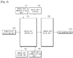
- FIG. 4 is a block diagram illustrating flow of control signals in an indoor unit included in an air conditioning apparatus according to one embodiment.
- the indoor unit 200 includes an indoor unit manipulation unit 232 allowing a user to input an operational command for the indoor unit 200 therethrough, an indoor unit display 233 to display operational information about the indoor unit 200, a temperature detection unit 234 to detect the temperature of an indoor space where the indoor unit 200 is located, an indoor unit drive unit 236 to drive an airblowing fan 222a of the indoor unit 200, an indoor unit storage unit 237 to store programs and data related to operation of the indoor unit 200, an indoor unit communication unit 238 to communicate with the outdoor unit 100, and an indoor unit controller 231 to control respective constituents included in the indoor unit 200.
- an indoor unit manipulation unit 232 allowing a user to input an operational command for the indoor unit 200 therethrough
- an indoor unit display 233 to display operational information about the indoor unit 200
- a temperature detection unit 234 to detect the temperature of an indoor space where the indoor unit 200 is located
- an indoor unit drive unit 236 to drive an airblowing fan 222a of the indoor unit 200
- an indoor unit storage unit 237 to store programs and data related to
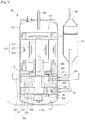
- FIG. 5 is a lateral cross-sectional view illustrating a compressor and an accumulator included in an air conditioning apparatus according to one embodiment.
- the compressor 300 may be provided with a casing 310 arranged adjacent to the accumulator 125 having an inlet 397 and forming an external appearance of the compressor 300, and a motor unit 320 installed at an inner upper portion of the casing 310, and a compression unit 330 installed at an inner lower portion of the casing 310 connected to the motor unit 320 through a rotating shaft 321 of the motor unit 320.
- a refrigerant accommodation portion 311 to accommodate the high-pressure gaseous refrigerant compressed in the compression unit 330
- a compressor oil accommodation portion 313 to accommodate compressor oil which allows smooth rotation of the motor unit 320 and lowers the temperature in the casing 310.
- a compressor oil introduction port 313a is provided at an upper portion of the compressor oil accommodation portion 313 to allow the compressor oil to be introduced into the compression unit 330.
- FIG. 6 is a perspective view illustrating a motor unit of a compressor included in an air conditioning apparatus according to one embodiment.
- the motor unit 320 includes a cylindrical stator 323 fixed to the inner surface of the casing 310, and a rotator 322 rotatably installed in the stator 323 and having a central portion coupled to the rotating shaft 321.
- the stator 323 includes a plurality of coils 323a to generate a rotating magnetic field, and a coil fixing member 323b to fix the coils 323a.
- the shape of the rotator 322 may vary depending upon the type of the motor unit 320. That is, in the case that the motor unit 320 is provided with a synchronous motor, the rotator 322 may include a plurality of permanent magnets (not shown) arranged along the outer circumferential surface of the rotating shaft 321. In the case that the motor unit 320 is provided with an induction motor, the rotator 322 may include a plurality of coils to induce a magnetic field.
- the motor unit 320 may rotate the rotator 322 through interaction between a magnetic field produced by the stator 323 and a magnetic field produced by the rotator 322, thereby transferring rotation of the rotator 322 to the compression unit 330 through the rotating shaft 321 to drive the compression unit 330 through rotation.
- FIG. 7 is an exploded perspective view illustrating a compression unit of a compressor included in an air conditioning apparatus according to one embodiment, and FIG. 8 shows a cross-sectional view taken along line A-A' of FIG. 5 .
- the compression unit 330 may include a plurality of cylinders 332 and 334 arranged in the casing 310 and respectively provided with sectionalized compression spaces 350 and 352, and a plurality of bearing plates 340, 342 and 344 to cover the tops and bottoms of the cylinders 332 and 334 to define the compression spaces 350 and 352 in conjunction with the cylinders 332 and 334.
- the cylinders 332 and 334 respectively include compression spaces 350 and 352 defined therein, rolling pistons 360 and 362 to rotate about different centers in the compression spaces 350 and 352, vanes 371 and 381 to respectively contact the outer circumferences of the rolling pistons 360 and 362 and divide each of the compression spaces 350 and 352 into a suction chamber 354 and a compression chamber 355, and vane chambers 370 and 380 formed recessed outward of the compression spaces 350 and 352 to allow the vanes 371 and 381 to move forward and backward.
- the cylinders 332 and 334 may include a first cylinder 332 provided with the first compression space 350, and a second cylinder 334 disposed at the lower side of the first cylinder 332 and provided with the second compression space 352. While the compressor 300 is illustrated in FIGS. 7 and 8 as having two cylinders 332 and 334, embodiments of the present disclosure are not limited thereto.
- the compressor 300 may include one, three, or more cylinders.
- the bearing plates 340, 342 and 344 cover the tops and bottoms of the cylinders 332 and 334 to define the compression spaces 350 and 352 in conjunction with the cylinders 332 and 334.
- the bearing plates 340, 342 and 344 may include a second bearing plate 342 provided between the first cylinder 332 and the second cylinder 334, a first bearing plate 340 provided at the upper side of the first cylinder 332 to close the upper opening of the first compression space 350, and a third bearing plate 344 provided at the lower side of the second cylinder 334 to close the lower opening of the second compression space 352.
- the bearing plates 340, 342 and 344 support the rotating shaft 321 of the motor unit 320.
- the first cylinder 332 and the second cylinder 334 are respectively provided with a first suction port 391 and a second suction port 393, which are respectively connected to a first suction pipe 390 and a second suction pipe 392 to allow the gaseous refrigerant to be introduced into the first compression space 350 and the second compression space 352.
- the first bearing plate 340 and the third bearing plate 344 are respectively provided with a first discharge port 394 and a second discharge port 395 to discharge the gaseous refrigerant compressed in the first compression space 350 and the second compression space 352 to the interior of the casing 310.
- the interior of the casing 310 is maintained at a high pressure by the compressed gaseous refrigerant discharged through the discharge ports 394 and 395.
- the compressed gaseous refrigerant in the casing 310 is discharged to an outer space through a discharge pipe 396 provided at the top of the casing 310.
- the rotating shaft 321 penetrates the centers of the first compression space 350 and the second compression space 352, and is connected to the first rolling piston 360 and the second rolling piston 362 respectively provided in the first compression space 350 and the second compression space 352.
- the first rolling piston 360 and the second rolling piston 362 may be coupled to the rotating shaft 321. More specifically, the first rolling piston 360 and the second rolling piston 362 may be coupled to the rotating shaft 321, with the centers thereof misaligned. Due to this configuration, the first rolling piston 360 and the second rolling piston 362 may eccentrically rotate within the compression spaces 350 and 352, compressing the gaseous refrigerant.
- the vanes 371 and 381 include a first vane 371 provided to the first cylinder 332 and a second vane 381 provided to the second cylinder 334.
- the vanes 371 and 381 are arranged to respectively contact the outer circumferences of the rolling pistons 360 and 362 to divide each of the compression spaces 350 and 352 into the suction chamber 354 and the compression chamber 355.
- the vane chambers 370 and 380 are formed to be recessed outward of the compression spaces 350 and 352.
- the vane chambers 370 and 380 include a first vane chamber 370 provided in the first cylinder 332 and a second vane chamber 380 provided in the second cylinder 334.
- the first vane chamber 370 includes a first vane guide 372 to guide the first vane 371, which is configured to contact the first rolling piston 360, such that the first vane 371 moves forward and backward in conjunction with rotation of the first rolling piston 360, and a first vane spring accommodation portion 373 provided therein with a first vane spring 374 to press the first vane 371 against the first rolling piston 360 to allow the first vane 371 to sectionalize the first compression space 350.
- the second vane chamber 380 includes a second vane guide 382 formed to be recessed outside of the second compression space 352 to guide the second vane 381, and a second vane spring accommodation portion 383 provided therein with a second vane spring 384 to press the second vane 381 against the second rolling piston 362 to allow the second vane 381 to sectionalize the second compression space 350.
- FIGS. 9 to 11 are views illustrating operation of a compressor included in an air conditioning apparatus according to one embodiment. Specifically FIGS. 9 to 11 schematically show a cross section of the first cylinder 332 shown in FIG. 8 to aid in understanding of operation of the compressor 300.
- a contact point P at which the outer circumferential surface of the first rolling piston 360 contacts the inner circumferential surface of the first cylinder 332 is positioned at the first suction port 391.
- the compression chamber 355 is defined by the outer circumferential surface of the first rolling piston 360, the inner circumferential surface of the first cylinder 332, and the right side surface of the first vane 371. The gaseous refrigerant suctioned by rotation of the rotating shaft 321 and the first rolling piston 360 fills the compression chamber 355.
- the space of the suction chamber 354 defined by the outer circumferential surface of the first rolling piston 360, the inner circumferential surface of the first cylinder 332, and the left side surface of the first vane 371 is gradually widened.
- the gaseous refrigerant in the accumulator 125 is suctioned into the suction chamber 354 through the first suction port 391.
- FIG. 10 which shows the point P of contact between the outer circumferential surface of the first rolling piston 360 and the inner circumferential surface of the first cylinder 332 having moved from the position shown in FIG. 9 to the opposite side facing the first vane 371 by rotation of the rotating shaft 321, the space of the compression chamber 355 decreases to about half the size of the space of the compression chamber 355 shown in FIG. 9 . Thereby, the pressure of the gaseous refrigerant of the compression chamber 355 increases about two fold.
- the space of the compression chamber 355 is narrowed, the space of the suction chamber 354 is gradually widened, and the gaseous refrigerant in the accumulator 125 is continuously suctioned into the suction chamber 354 through the first suction port 391.
- FIG. 11 which shows the point P of contact between the outer circumferential surface of the first rolling piston 360 and the inner circumferential surface of the first cylinder 332 having moved from the position shown in FIG. 10 to a position close to the first discharge port 394 by further rotation of the rotating shaft 321, the space of the compression chamber 355 is greatly reduced from the size of the space of the compression chamber 355 shown in FIG. 10 . Thereby, the gaseous refrigerant in the compression chamber 355 is compressed to a very high pressure.
- a pressure valve (not shown) maintaining the first discharge port 394 of the first cylinder 332 in a closed state is opened, and the high-pressure gaseous refrigerant in the compression chamber 355 is discharged to the refrigerant accommodation portion 311 of the compressor 300 through the first discharge port 394.
- the space of the compression chamber 355 is narrowed, the space of the suction chamber 354 is gradually widened, occupying most of the inner space of the first cylinder 332.
- the refrigerant represents all substances that exhibit a cooling effect, particularly, a fluid that is caused to circulate in a heat exchange cycle such as a refrigerating device, a heat pump, and an air conditioning apparatus to absorb heat from the surroundings through evaporation at a low-temperature side and release heat to the surroundings through condensation at a high-temperature side.
- the refrigerant is generally one of four kinds of compounds, i.e., a halocarbon compound, a hydrocarbon compound, an organic compound, and an inorganic compound.
- halocarbon compounds are widely used as refrigerants.
- a halocarbon compound is a compound obtained by substituting a hydrogen atom of methane (CH4) or ethane (C2H6) with a halogen atom such as a fluorine atom, a chlorine atom, or a bromine atom.
- a halogen atom such as a fluorine atom, a chlorine atom, or a bromine atom.
- each refrigerant is represented by a symbol made by adding a number given according to a formula defined by the International Organization for Standardization (ISO) to "R,” representing the word "refrigerant.”
- ISO International Organization for Standardization
- FIG. 12 is a view illustrating a refrigerant included in an air conditioning apparatus according to one embodiment. Specifically, FIG. 12 systematically shows the configuration of a methane-based hydrocarbon refrigerant with methane (CH4), carbon tetrachloride (CCl4) and carbon tetrafluoride (CF4) positioned at vertices.
- CH4 methane
- CCl4 carbon tetrachloride
- CF4 carbon tetrafluoride
- the refrigerant sequentially changes from R40 refrigerant (CH3C), to R30 refrigerant (CH2Cl2), to R20 refrigerant (CHCl3), and to R10 refrigerant (CCl4).
- CH3C refrigerant
- CH2Cl2 refrigerant
- CHCl3 refrigerant
- CCl4 refrigerant
- the refrigerant sequentially changes from R11 refrigerant (CCl3F), to R12 refrigerant (CCl2F2), to R13 refrigerant (CClF33), and to R14 refrigerant (CF4).
- R11 refrigerant Cl3F
- R12 refrigerant Cl2F2
- R13 refrigerant ClF33
- R14 refrigerant CF4
- the refrigerant sequentially changes from R41 refrigerant (CH3F), to R32 refrigerant (CH2F2), to R23 refrigerant (CHF3), and to R14 refrigerant (CF4).
- R41 refrigerant CH3F
- R32 refrigerant CH2F2
- R23 refrigerant CHF3
- R14 refrigerant CF4
- R50 refrigerant containing the greatest number of hydrogen atoms has the highest flammability. As the number of hydrogen atoms decreases, flammability of the refrigerant decreases.
- R10 refrigerant containing the greatest number of chlorine atoms has the highest toxicity. As the number of chlorine atoms decreases, toxicity of the refrigerant is lowered.
- R14 containing the greatest number of fluorine atoms has the highest stability. As the number of contained fluorine atoms decreases, stability decreases.
- R10 refrigerant, R11 refrigerant, R12 refrigerant, R13 refrigerant, and R14 refrigerant which do not contain any hydrogen atom, are fully halogenated refrigerants. These refrigerants are not easily decomposed in the atmosphere, thereby causing depletion of the ozone layer. That is, as the number of hydrogen atoms contained in the refrigerant decreases, the refrigerant is not easily decomposed in the atmosphere, causing depletion of the ozone layer.
- R12 refrigerant Cl2F2, dichloro-difluoro-methane
- CFC chlorofluorocarbon
- R12 refrigerant was identified as a primary cause of depletion of the ozone layer
- R22 CHClF2, chloro difluoro methane refrigerant, a hydrochlorofluorocarbon (HCFC)
- HCFC hydrochlorofluorocarbon
- GWP global warming potential
- ODP ozone depletion potential
- R410A which is created by mixing R32 and R125 in a weight ratio of 50 to 50
- R410B which is created by mixing R32 and R125 in a weight ratio of 45 to 55.
- R407A which is created by mixing R32, R123, and R134a in a weight ratio of 20:40:40
- R407B which is created by mixing R32, R123, and R134a in a weight ratio of 10:70:20
- R407C which is created by mixing R32, R123, and R134a in a weight ratio of 23:25:52
- R407D which is created by mixing R32, R123, and R134a in a weight ratio of 15:15:70.
- R32 single refrigerant and R32-mixed refrigerants have high boiling points and high critical point.
- the discharge temperature of the compressor using one of these refrigerants is 17.6 °C higher than in the case that R22 is used.
- discharge temperature is 20°C to 25°C higher than in the case that R22 refrigerant is used.
- the temperature of the compressor rises, which may deteriorate the compressor.
- the compressor is manufactured using a material selected with reference to the Resistible Temperature of 120 °C (thermal class E).
- the discharge temperature at which the refrigerant is discharged from the compressor exceeds 120 °C, and therefore the conventional compressor may be deformed due to high temperature.
- the coating member to insulate the coil of a motor unit included in the compressor and the coil fixing member to fix the coil are formed of an insulative material such as plastics, they are vulnerable to heat.
- FIG. 13 is a view showing representative substances of respective thermal classes.
- the thermal classes are defined in Japanese Industrial Standards (JIS) to classify insulators according to Resistible Temperatures. More specifically, each class represents the highest allowable temperature for a coil fixing member.
- JIS Japanese Industrial Standards
- each class represents the highest allowable temperature for a coil fixing member.
- an insulator from thermal class A should resist temperatures up to 105 °C. That is, insulators from thermal class A are not deformed at at least 85 °C.
- an insulator from thermal class E should resist temperatures up to 120 °C
- an insulator from thermal class B should resist temperatures up to 130 °C
- an insulator from thermal class F should resist temperatures up to 155 °C.
- substances belonging to thermal class F are inorganic materials such as mica, asbestos, and glass fiber.
- Adhesive materials from thermal class F include silicone alkyd resins.
- an insulation material whose Resistible Temperature is equal to or greater than 140 °C may be employed.
- a material from thermal class F Resistible Temperature 155 °C
- the coil 323b and the coil fixing member 323a provided in the motor unit 320 of the compressor 300 include an insulative material whose thermal resistance is determined according to the temperature at which the compressor 300 operates.
- the coil 323b includes a conductive material such as copper which is electrically conductive and a coating member applied to the surface of the conductive material.
- the coating member is formed of an insulative material to insulate neighboring parts of the coil 323b.
- the coil fixing member 323b to fix the coil 323b is formed of an insulative material to insulate neighboring parts of the coil 323a.
- the thermal resistances of the coating member included in the coil 323a and the coil fixing member 323b to fix the coil 323b are determined according to the temperature at which the compressor 300 operates.
- the discharge temperature of the air conditioning apparatus 1 is 20 °C to 25 °C higher than when conventional R22 is used in the air conditioning apparatus 1.
- the coils 323a and the coil fixing member 323b of the compressor 300 included in the air conditioning apparatus 1 using R32 are formed of an insulation material whose Resistible Temperature is 140 °C, particularly, an insulation material from thermal class F such that the compressor 300 is operable at at least 140 °C.
- the coating material applied to the surface of the coil 323a employs a coating material from thermal class F such as a silicone alkyd resin or a silicone resin
- the coil fixing member 323b to fix the coil 323a employs an inorganic material such as mica, asbestos, and glass fiber.
- the coils 323a and the coil fixing member 323b of the motor unit 320 may not be deformed at the discharge temperature of R32, 140 °C.
- the compressor 300 includes a refrigerant accommodation portion 311 to accommodate a high-pressure refrigerant in the casing 310, and a compressor oil accommodation portion 313 to accommodate compressor oil.
- the compressor oil performs functions including lubrication of components of the compressor 300 to reduce friction between components, heat dissipation of absorbing heat produced in the compressor 300 and releasing the heat to the outer space, and sealing the compressor 300 to prevent leakage of the refrigerant.
- Compressor oils are classified into mineral oil, which is produced by adding an additive to crude oil having undergone a refining process, and synthetic oil, which is synthesized from naphtha to have a proper chemical structure.
- the replacement period of mineral oil is about 1,000 hours, while the replacement period of synthetic oil is 4,000 hours, which is significantly longer than the replacement period of mineral oil.
- the compressor oil is stored in the compressor oil accommodation portion 313, and is introduced into the compression unit 330 through the compressor oil introduction port 313a provided at the lower portion of the compression unit 330.
- the compressor oil introduced into the compression unit 330 lowers friction between the rotating shaft 321 of the motor unit 320 and the bearing plates 340, 342 and 344 of the compression unit 330 such that the rotating shaft 321 of the motor unit 320 rotates smoothly.
- the compressor oil lowers friction between the cylinders 332 and 334 and the rolling pistons 360 and 362 such that the rolling pistons 360 and 362 smoothly rotate in the cylinders 332 and 334.
- the compressor oil prevents the high-pressure refrigerant positioned in the compression chamber 355 from being introduced into the suction chamber 354. That is, the compressor oil seals a fine gap between the rolling pistons 360 and 362 and the vanes 371 and 381, thereby preventing the high-pressure refrigerant in the compression chamber 355 from being introduced into the suction chamber 354 of low pressure through the gap between the rolling pistons 360 and 362 and the vanes 371 and 381.
- the compressor oil is positioned in the cylinders 332 and 334.
- the compressor oil positioned in the cylinders 332 and 334 is also discharged from the compression unit 330 to the refrigerant accommodation portion 313.
- the compressor oil absorbs heat from the refrigerant, lowering the discharge temperature of the refrigerant. In other words, the compressor oil may lower the operational temperature of the compressor 300.
- compressor oil having a high heat capacity performs excellent heat dissipation.
- heat capacity is the quantity that specifies the amount of heat required to increase the temperature of an object by 1 °C (K).
- the heat capacity of an object is proportional to the amount of heat applied and inversely proportional to change in temperature. That is, when the same amount of heat is applied, an object exhibiting a small change in temperature has a high heat capacity, and an object exhibiting a large change in temperature has a low heat capacity.
- the heat capacity of an object is proportional to the mass and specific heat thereof. That is, the relation between heat capacity, mass and specific heat of an object is given as Equation 2.
- C c ⁇ m
- the heat capacity may be increased by increasing the specific heat or the mass of the object.
- the specific heat of a substance is a ratio of the amount of heat required to increase the temperature of the unit mass (1kg) of a substance by 1 °C (K) to the amount of heat required to increase the temperature of the unit mass (1kg) of water by 1 °C (K).
- Specific heat of a substance may be defined using Equation 3.
- C Q m ⁇ t
- Specific heat is a unique property of a substance. Different substances have different specific heats. Accordingly, for the compressor oil to absorb a large amount of heat from the compressor 300 with a small change in temperature, a substance of a high specific heat may need to be employed as the compressor oil. That is, a different substance may need to be employed as the compressor oil.
- FIG. 14 is a view illustrating a compressor oil accommodation portion of a compressor included in an air conditioning apparatus according to one embodiment.
- part (a) illustrates the case of increasing the size of the compressor oil accommodation portion 313 included in the compressor 300 to accommodate a large amount of the compressor oil
- the compressor oil accommodation portion 313 is formed deep to allow the compressor 300 to accommodate a large amount of compressor oil. That is, by increasing the depth of the compressor oil accommodation portion 313 while keeping the depth of the other portions of the compressor 300 constant, the amount of the compressor oil accommodated in the compressor 300 may be increased.
- the vertical axis represents the depth of the compressor oil accommodation portion 313.
- the depth of the compressor oil accommodation portion 313 increases. Thereby, the compressor 300 may accommodate a larger amount of the compressor oil.
- the lower horizontal axis represents the compressor oil volume fraction.
- the C.O.V. compressor oil volume
- the (E.V.C.) effective volume of the interior of the compressor
- the volume of the compressor 300 excluding the volume of the motor unit 320 and the compression unit 330 i.e., the volume of the empty space in the compressor 300.
- the solid line represents the compressor oil volume fraction according to the depth of the compressor oil accommodation portion 313.
- the compressor oil volume fraction exponentially increases. In other words, as the depth of the compressor oil accommodation portion 313 increases, the rate of increase of the compressor oil volume fraction increases.
- the upper horizontal axis represents discharge temperature difference.
- the discharge temperature difference is the difference in temperature between the refrigerant discharged through the discharge ports 394 and 395 (see FIG. 5 ) of the cylinders 332 and 334 (see FIG. 5 ) included in the compressor 300 and the refrigerant discharged from the discharge pipe 396 (see FIG. 5 ) of the compressor 300.
- a large discharge temperature difference suggests that the high-temperature, high-pressure refrigerant discharged from the cylinders 332 and 334 (see FIG. 5 ) has been cooled in the refrigerant accommodation portion 311 (see FIG. 5 ) and discharged to the discharge pipe 396 (see FIG. 5 ) of the compressor 300. In other words, it suggests that the temperature of the compressor 300 has been lowered.
- the dotted line represents change of the discharge temperature difference according to depth of the compressor oil accommodation portion 313. Referring to this dotted line, as the depth of the compressor oil accommodation portion 313 increases, the discharge temperature difference increases logarithmically. In other words, as the depth of the compressor oil accommodation portion 313 increases, the rate of increase of the discharge temperature difference is lowered.
- the compressor oil volume fraction at which the discharge temperature difference is saturated and thus not increased any more is 35 % to 45 %. In other words, after the compressor oil volume fraction becomes 35% to 45%, the operational temperature of the compressor 300 is not lowered any more, or change in the operational temperature of the compressor 300 is negligible.
- a proper discharge temperature of the refrigerant may be obtained when the size of the compressor oil accommodation portion 313 is set such that the compressor oil volume fraction is 35% to 45%.
- Increase in the discharge temperature of the refrigerant discharged from the cylinder is mainly caused by two events.
- the temperature of the refrigerant is increased by increase in collision among refrigerant particles and transfer of frictional heat of the compressor to the refrigerant, which occur during compression of the refrigerant.
- increase in the temperature of the refrigerant by increase in collision among refrigerant particles during compression of the refrigerant is related to physical properties of the refrigerant, and may be addressed by employing a different kind of refrigerant.
- increase in the temperature of the refrigerant by transfer of frictional heat of the compressor to the refrigerant occurring during compression of the refrigerant may be addressed by reducing the frictional heat of the compressor.
- the frictional heat may be reduced by enhancing the lubrication function of the compressor oil.
- the compressor oil included in the compressor of an air conditioning apparatus includes carbon nanoparticles.
- the compressor oil includes nanoparticles whose size is between about 3 nm and 10 nm such that the weight ratio of the carbon nanoparticles becomes between about 0.01 wt. % and about 0.3 wt. %.
- the carbon nanoparticles represent carbon particles whose size ranges from a few nanometers (a nanometer is one billionth of a meter) to a few hundred nanometers.
- a representative type of carbon nanoparticles is a fullerene, which has a spherical or ellipsoidal shape.
- Fullerene refers to any carbon particles at nanometer scale including C60 having the form of a soccer ball through covalent bonding of 60 carbon atoms, C70 in the form of an ellipsoid, C76, C78, C82, C90, C94 and C96.
- C60 is produced through covalent boding of 60 carbon atoms, and contains 12 five-member rings and 20 six-member rings.
- C60 whose diameter is about 1 nm, is a representative carbon nanoparticle.
- Fullerenes are stronger than diamond and are slippery. Due to strong covalent bonding of carbon atoms, fullerenes have low reactivity and are nontoxic to humans. In addition, fullerenes absorb light and easily acquire an electron.
- carbon nanoparticles represented by fullerenes
- the lubrication function of the compressor oil may be enhanced.
- carbon nanoparticles are inert substances that do not react to the compressor oil at high temperature.
- the carbon nanoparticle has a spherical shape. Accordingly, it does not stick to the surfaces of objects subjected to lubrication, but rolls on the surfaces, greatly reducing friction between objects.
- FIG. 15 is an enlarged view showing region B of FIG. 5 . Specifically, FIG. 15 is a view illustrating contact between the bearing plates 340, 342 and 344 of the compression unit 330 and the rotating shaft 321 of the motor unit 320 inserted into the bearing plates 340, 342 and 344.
- the rotating shaft 321 inserted into the bearing plates 340, 342 and 344 contacts and is fixed by the bearing plates 340, 342 and 344.
- friction is produced between the outer circumferential surface of the rotating shaft 321 and the inner circumferential surfaces of the bearing plates 340, 342 and 344.
- the spherical carbon nanoparticles function as bearings in rolling contact with the outer circumferential surface of the rotating shaft 321 and the inner circumferential surfaces of the bearing plates 340, 342 and 344, thereby reducing friction between the rotating shaft 321 and the bearing plates 340, 342 and 344.
- the carbon nanoparticles fill a spike-shaped crevice which may be produced on the outer circumferential surface of the rotating shaft 321 and the inner circumferential surfaces of the bearing plates 340, 342 and 344, reducing friction.
- a spike-shaped crevice may be produced on the outer circumferential surface of the rotating shaft 321 and the inner circumferential surfaces of the bearing plates 340, 342 and 344 by external force forcing the rotating shaft 321 to contact the bearing plates 340, 342 and 344, as shown in FIG. 15 , part (a).
- This spike-shaped crevice increases friction between the rotating shaft 321 and the bearing plates 340, 342 and 344.
- the compressor oil is simply applied to the outer circumferential surface of the rotating shaft 321 and the inner circumferential surfaces of the bearing plates 340, 342 and 344 to form a certain thickness, as shown in FIG. 15 , part (b). Accordingly, friction between the rotating shaft 321 and the bearing plates 340, 342 and 344 resulting from the spike-shaped crevice may not be reduced.
- the carbon nanoparticles contained in the compressor oil fill the spike-shaped crevice formed on the outer circumferential surface of the rotating shaft 321 and the inner circumferential surfaces of the bearing plates 340, 342 and 344, as shown in FIG. 15 , part (c), thereby reducing friction between the rotating shaft 321 and the bearing plates 340, 342 and 344 caused by the spike-shaped crevice.
- the compressor oil containing carbon nanoparticles reduces friction between the rotating shaft 321 and the bearing plates 340, 342 and 344, thereby reducing frictional heat.
- the temperature in the cylinders 350 and 352 is lowered and the discharge temperature of the refrigerant discharged from the cylinders 350 and 352 is also reduced.
- reliability and performance of the compressor may be secured at high operational temperature of the compressor by using an insulation material from thermal F class for the coils and coil fixing member included in the motor unit of the compressor.
- the heat capacity of the compressor oil may be increased.
- carbon nanoparticles to the compressor oil, friction between components included in the compressor may be reduced, and the operational temperature of the compressor may be lowered. Thereby, reliability and performance of the compressor may be secured.
Landscapes
- Engineering & Computer Science (AREA)
- Chemical & Material Sciences (AREA)
- Mechanical Engineering (AREA)
- General Engineering & Computer Science (AREA)
- Physics & Mathematics (AREA)
- Thermal Sciences (AREA)
- Chemical Kinetics & Catalysis (AREA)
- Organic Chemistry (AREA)
- Oil, Petroleum & Natural Gas (AREA)
- Inorganic Chemistry (AREA)
- General Chemical & Material Sciences (AREA)
- Materials Engineering (AREA)
- Combustion & Propulsion (AREA)
- Applications Or Details Of Rotary Compressors (AREA)
- Compressor (AREA)
- Insulation, Fastening Of Motor, Generator Windings (AREA)
Claims (13)
- Klimaanlage (1), die Folgendes umfasst:einen Kompressor (300) zum Komprimieren eines Kältemittels;einen Außenwärmetauscher (122) zum Durchführen eines Wärmeaustauschs zwischen Außenluft und dem Kältemittel;einen Innenwärmetauscher (222) zum Durchführen eines Wärmeaustauschs zwischen Innenluft und dem Kältemittel; undein Expansionsventil (124, 224) zum Abbauen des Drucks des Kältemittels,
wobei:das Kältemittel aus Fluorkohlenwasserstoff (HFC) gebildet ist;der Kompressor (300) eine Kompressionseinheit (330) zum Komprimieren des Kältemittels, eine Motoreinheit (320) zum Versorgen der Kompressionseinheit (330) mit Drehkraft über eine mit der Kompressionseinheit (330) verbundene Drehwelle (321) und einen Ölaufnahmeabschnitt (313) zum Speichern von Öl umfasst, um Reibung zwischen der Drehwelle (321) und der Kompressionseinheit (330) zu reduzieren und eine Temperatur des Kompressors (300) zu senken; dadurch gekennzeichnet, dassdas Öl ein Kohlenstoffnanopartikel enthält; undder Kompressorölanteil 35% bis 45% beträgt, wobei der Kompressorölanteil das Ölvolumen als Prozentanteil des effektiven Volumens eines Innenraums des Kompressors (300) ist und das effektive Volumen ein Volumen repräsentiert, das durch Subtrahieren von Volumen der Motoreinheit (320) und der Kompressoreinheit (330) von einem Gesamtvolumen des Kompressors (300) erhalten wird. - Klimaanlage (1) nach Anspruch 1, wobei das Kältemittel Methylenfluorid umfasst, wobei der Prozentanteil des Methylenfluorids mindestens 40% beträgt.
- Klimaanlage (1) nach Anspruch 2, wobei das Kältemittel ferner Pentafluorethan und/oder Tetrafluorethan umfasst.
- Klimaanlage (1) nach Anspruch 1, wobei eine Massefraktion der im Öl enthaltenen Kohlenstoffnanopartikel etwa 0,01 % bis etwa 0,3 % einer Masse des Öls beträgt.
- Klimaanlage (1) nach Anspruch 4, wobei eine Größe des im Öl enthaltenen Kohlenstoffnanopartikels zwischen etwa 3 Nanometern und 10 Nanometern liegt.
- Klimaanlage (1) nach Anspruch 5, wobei das Kohlenstoffnanopartikel ein Fulleren umfasst, das in einer sphärischen oder ellipsoiden Form ausgebildet ist.
- Klimaanlage (1) nach Anspruch 6, wobei das Fulleren C60 umfasst, das durch kovalente Bindung von sechzig Kohlenstoffatomen mit einer sphärischen Form versehen ist.
- Klimaanlage (1) nach Anspruch 1, wobei eine Temperatur des aus dem Kompressor (300) abgegebenen Kältemittels 8 °C niedriger ist als eine Temperatur des aus der Kompressionseinheit (330) abgegebenen Kältemittels.
- Klimaanlage (1) nach Anspruch 1, wobei die Motoreinheit (320) einen an einem Innenraum des Kompressors (300) befestigten Stator (323) und einen mit der Drehwelle (321) verbundenen und drehbar im Stator (323) angeordneten Rotor (322) aufweist, wobei der Stator (323) eine Spule (323a) zum Erzeugen eines rotierenden Magnetfeldes und ein Spulenbefestigungselement (323b) zum Befestigen der Spule (323a) aufweist.
- Klimaanlage (1) nach Anspruch 9, wobei ein Isolierelement zum Isolieren der Spule (323a) aus einem Isoliermaterial mit einer widerstehbaren Temperatur von 140 °C gebildet ist.
- Klimaanlage (1) nach Anspruch 10, wobei das Isolierelement ein Silikonalkydharz oder ein Silikonharz ist.
- Klimaanlage (1) nach Anspruch 9, wobei das Spulenbefestigungselement (323b) aus einem Material der Wärmeklasse F gebildet ist, das Temperaturen von bis zu 155 °C zulässt.
- Klimaanlage nach Anspruch 9, wobei das Spulenbefestigungselement (323b) aus mindestens einem aus Glimmer, Asbest und Glasfaser gebildet ist.
Applications Claiming Priority (2)
| Application Number | Priority Date | Filing Date | Title |
|---|---|---|---|
| KR1020130083449A KR101525849B1 (ko) | 2013-07-16 | 2013-07-16 | 압축기 및 이를 이용한 공기조화기 |
| PCT/KR2014/006290 WO2015008982A1 (en) | 2013-07-16 | 2014-07-14 | Compressor and air conditioning apparatus using the same |
Publications (3)
| Publication Number | Publication Date |
|---|---|
| EP3022502A1 EP3022502A1 (de) | 2016-05-25 |
| EP3022502A4 EP3022502A4 (de) | 2016-12-14 |
| EP3022502B1 true EP3022502B1 (de) | 2021-06-30 |
Family
ID=52342468
Family Applications (1)
| Application Number | Title | Priority Date | Filing Date |
|---|---|---|---|
| EP14825950.0A Active EP3022502B1 (de) | 2013-07-16 | 2014-07-14 | Klimaanlage |
Country Status (9)
| Country | Link |
|---|---|
| US (1) | US9499760B2 (de) |
| EP (1) | EP3022502B1 (de) |
| KR (1) | KR101525849B1 (de) |
| CN (1) | CN105431690B (de) |
| AU (1) | AU2014291086B2 (de) |
| BR (1) | BR112015032255A2 (de) |
| ES (1) | ES2882092T3 (de) |
| RU (1) | RU2642550C2 (de) |
| WO (1) | WO2015008982A1 (de) |
Families Citing this family (14)
| Publication number | Priority date | Publication date | Assignee | Title |
|---|---|---|---|---|
| JP5697710B2 (ja) * | 2013-04-08 | 2015-04-08 | 三菱電機株式会社 | 冷凍サイクル装置 |
| KR20160055583A (ko) * | 2014-11-10 | 2016-05-18 | 삼성전자주식회사 | 히트 펌프 |
| JP6624809B2 (ja) * | 2015-05-20 | 2019-12-25 | 三菱電機株式会社 | 圧縮機、及びその圧縮機を備えたヒートポンプ装置 |
| KR101667979B1 (ko) | 2015-06-19 | 2016-10-21 | 한국생산기술연구원 | 제습 및 가습 기능을 갖는 공기조화기와 이를 이용한 제습냉방 및 가습난방 방법 |
| CN105041660A (zh) * | 2015-07-15 | 2015-11-11 | 广东美芝制冷设备有限公司 | 旋转式压缩机及含有该旋转式压缩机的制冷设备 |
| CN108603506B (zh) * | 2016-02-19 | 2020-11-03 | 松下知识产权经营株式会社 | 制冷剂压缩机和使用其的制冷装置 |
| CN106905933B (zh) * | 2016-11-27 | 2020-11-17 | 青岛康普顿科技股份有限公司 | 一种含羧基化富勒烯的有机型发动机冷却液及其制备方法 |
| WO2019112307A1 (en) * | 2017-12-05 | 2019-06-13 | Samsung Electronics Co., Ltd. | Air conditioner |
| CN111511874A (zh) * | 2017-12-18 | 2020-08-07 | 大金工业株式会社 | 制冷循环装置 |
| KR102662665B1 (ko) | 2022-06-15 | 2024-05-08 | 한국생산기술연구원 | 열교환기의 폐열을 이용한 제습 환기 냉방 장치 및 제습 환기 냉방 방법 |
| KR102759027B1 (ko) | 2022-10-25 | 2025-01-23 | 한국생산기술연구원 | 냉매 대 흡착제 직접 열교환 방식의 잠열제거 환기 냉방시스템 및 환기 냉방 방법 |
| KR20240167550A (ko) | 2023-05-19 | 2024-11-27 | 한국생산기술연구원 | 에너지 효율이 증대된 제습 환기 냉방 장치 및 제습 환기 냉방 방법 |
| KR102717879B1 (ko) * | 2023-10-11 | 2024-10-15 | 주영남 | 탄소저감을 위한 폐유증류장치 |
| KR102717875B1 (ko) * | 2023-10-11 | 2024-10-15 | 주영남 | 탄소배출 저감을 위한 폐유정제시스템 |
Family Cites Families (11)
| Publication number | Priority date | Publication date | Assignee | Title |
|---|---|---|---|---|
| JPH09303264A (ja) * | 1996-05-10 | 1997-11-25 | Matsushita Electric Ind Co Ltd | 冷凍機用圧縮機 |
| JPH10159734A (ja) * | 1996-11-28 | 1998-06-16 | Sanyo Electric Co Ltd | 冷凍装置 |
| KR19980042789U (ko) * | 1996-12-24 | 1998-09-25 | 박병재 | 자동차용 키 홀더 |
| KR20010014817A (ko) * | 1999-07-06 | 2001-02-26 | 다카노 야스아키 | 냉매압축기 및 이것을 이용한 냉동냉방장치 |
| MY125381A (en) * | 2000-03-10 | 2006-07-31 | Sanyo Electric Co | Refrigerating device utilizing carbon dioxide as a refrigerant. |
| KR100591313B1 (ko) * | 2003-11-28 | 2006-06-19 | 엘지전자 주식회사 | 압축기용 윤활유 |
| US7708903B2 (en) * | 2005-11-01 | 2010-05-04 | E.I. Du Pont De Nemours And Company | Compositions comprising fluoroolefins and uses thereof |
| JP2007262298A (ja) | 2006-03-29 | 2007-10-11 | Fujitsu General Ltd | 潤滑油、冷媒回路装置および過冷却度の改善方法 |
| CN102472533A (zh) * | 2010-03-17 | 2012-05-23 | 松下电器产业株式会社 | 制冷循环装置 |
| EP2592278B1 (de) * | 2010-07-08 | 2016-11-23 | Panasonic Corporation | Drehkompressor und kühlkreislaufvorrichtung |
| JP2013120029A (ja) * | 2011-12-08 | 2013-06-17 | Panasonic Corp | 空気調和機 |
-
2013
- 2013-07-16 KR KR1020130083449A patent/KR101525849B1/ko active Active
-
2014
- 2014-05-20 US US14/282,233 patent/US9499760B2/en active Active
- 2014-07-14 BR BR112015032255A patent/BR112015032255A2/pt not_active Application Discontinuation
- 2014-07-14 CN CN201480040409.4A patent/CN105431690B/zh active Active
- 2014-07-14 ES ES14825950T patent/ES2882092T3/es active Active
- 2014-07-14 AU AU2014291086A patent/AU2014291086B2/en not_active Ceased
- 2014-07-14 EP EP14825950.0A patent/EP3022502B1/de active Active
- 2014-07-14 RU RU2016101059A patent/RU2642550C2/ru active
- 2014-07-14 WO PCT/KR2014/006290 patent/WO2015008982A1/en not_active Ceased
Non-Patent Citations (1)
| Title |
|---|
| None * |
Also Published As
| Publication number | Publication date |
|---|---|
| KR20150009245A (ko) | 2015-01-26 |
| AU2014291086A1 (en) | 2015-12-17 |
| CN105431690A (zh) | 2016-03-23 |
| RU2016101059A (ru) | 2017-07-20 |
| KR101525849B1 (ko) | 2015-06-05 |
| US20150020539A1 (en) | 2015-01-22 |
| RU2642550C2 (ru) | 2018-01-25 |
| BR112015032255A2 (pt) | 2017-07-25 |
| EP3022502A4 (de) | 2016-12-14 |
| EP3022502A1 (de) | 2016-05-25 |
| WO2015008982A1 (en) | 2015-01-22 |
| ES2882092T3 (es) | 2021-12-01 |
| AU2014291086B2 (en) | 2016-09-08 |
| US9499760B2 (en) | 2016-11-22 |
| CN105431690B (zh) | 2018-10-12 |
Similar Documents
| Publication | Publication Date | Title |
|---|---|---|
| EP3022502B1 (de) | Klimaanlage | |
| JP6105511B2 (ja) | ヒートポンプ装置 | |
| US9315708B2 (en) | Heat-transfer compositions exhibiting improved miscibility with the lubricating oil | |
| US8858825B2 (en) | Heat transfer compositions comprising 2,3,3,3-tetrafluoropropene and ammonia | |
| TWI633179B (zh) | 烷基全氟烯醚及其混合物於高溫熱泵的應用 | |
| CN106574802A (zh) | 热循环系统 | |
| CN112088283A (zh) | 冷冻循环装置 | |
| CN105452417A (zh) | 热循环用工作介质、热循环系统用组合物以及热循环系统 | |
| CN109072900A (zh) | 压缩机和热循环系统 | |
| JPWO2015136981A1 (ja) | 圧縮機及び冷凍サイクル装置 | |
| BRPI0719479B1 (pt) | sistema de transferência de calor, refrigerador, câmara frigorífica, resfriador, expositor de produtos, congelador, equipamento de ar condicionado, método para retroajustar um sistema de transferência de calor e sistema de refrigeração ou condicionamento de ar | |
| JP2017133827A (ja) | ヒートポンプ装置 | |
| WO2020050020A1 (ja) | 電動圧縮機及びこれを用いた冷凍空調装置 | |
| WO2020049844A1 (ja) | 圧縮機、及び、これを備える冷凍サイクル装置 | |
| Verma et al. | A review of alternative to R134a (CH3CH2F) refrigerant | |
| Satsangi et al. | R134a refrigerant in vapour compression cycle: a review paper | |
| JP6899360B2 (ja) | 冷凍サイクル装置 | |
| JP2019089979A (ja) | 冷凍サイクル用作動媒体の不均化抑制固形材料、並びに、これを用いた圧縮機および冷凍サイクルシステム | |
| AU2006208885A1 (en) | Heat pump | |
| Yokozeki et al. | Heat Capacities and Joule–Thomson Coefficients of HFC Refrigerants | |
| WO2025005071A1 (ja) | 冷凍サイクル用作動媒体の不均化反応の抑制方法、冷凍サイクル用作動媒体、並びに冷凍サイクル装置 | |
| AU2016231462B2 (en) | Heat-transfer compositions exhibiting improved miscibility with the lubricating oil | |
| WO2025005070A1 (ja) | 冷凍サイクル用作動媒体の不均化反応の抑制方法、冷凍サイクル用作動媒体、並びに冷凍サイクル装置 | |
| AU2015202362B2 (en) | Heat-transfer compositions exhibiting improved miscibility with the lubricating oil | |
| Xu et al. | R32 Scroll Compressors Technology |
Legal Events
| Date | Code | Title | Description |
|---|---|---|---|
| PUAI | Public reference made under article 153(3) epc to a published international application that has entered the european phase |
Free format text: ORIGINAL CODE: 0009012 |
|
| 17P | Request for examination filed |
Effective date: 20151120 |
|
| AK | Designated contracting states |
Kind code of ref document: A1 Designated state(s): AL AT BE BG CH CY CZ DE DK EE ES FI FR GB GR HR HU IE IS IT LI LT LU LV MC MK MT NL NO PL PT RO RS SE SI SK SM TR |
|
| AX | Request for extension of the european patent |
Extension state: BA ME |
|
| DAX | Request for extension of the european patent (deleted) | ||
| REG | Reference to a national code |
Ref country code: DE Ref legal event code: R079 Ref document number: 602014078472 Country of ref document: DE Free format text: PREVIOUS MAIN CLASS: F25B0001000000 Ipc: F25B0001040000 |
|
| A4 | Supplementary search report drawn up and despatched |
Effective date: 20161114 |
|
| RIC1 | Information provided on ipc code assigned before grant |
Ipc: C10M 125/02 20060101ALI20161108BHEP Ipc: F25B 13/00 20060101ALI20161108BHEP Ipc: F04C 23/00 20060101ALI20161108BHEP Ipc: F25B 49/02 20060101ALI20161108BHEP Ipc: C09K 5/04 20060101ALI20161108BHEP Ipc: F04C 18/356 20060101ALI20161108BHEP Ipc: F25B 1/04 20060101AFI20161108BHEP Ipc: C10M 171/00 20060101ALI20161108BHEP Ipc: F25B 31/00 20060101ALI20161108BHEP |
|
| STAA | Information on the status of an ep patent application or granted ep patent |
Free format text: STATUS: EXAMINATION IS IN PROGRESS |
|
| 17Q | First examination report despatched |
Effective date: 20200529 |
|
| GRAP | Despatch of communication of intention to grant a patent |
Free format text: ORIGINAL CODE: EPIDOSNIGR1 |
|
| STAA | Information on the status of an ep patent application or granted ep patent |
Free format text: STATUS: GRANT OF PATENT IS INTENDED |
|
| INTG | Intention to grant announced |
Effective date: 20210303 |
|
| GRAS | Grant fee paid |
Free format text: ORIGINAL CODE: EPIDOSNIGR3 |
|
| GRAA | (expected) grant |
Free format text: ORIGINAL CODE: 0009210 |
|
| STAA | Information on the status of an ep patent application or granted ep patent |
Free format text: STATUS: THE PATENT HAS BEEN GRANTED |
|
| AK | Designated contracting states |
Kind code of ref document: B1 Designated state(s): AL AT BE BG CH CY CZ DE DK EE ES FI FR GB GR HR HU IE IS IT LI LT LU LV MC MK MT NL NO PL PT RO RS SE SI SK SM TR |
|
| REG | Reference to a national code |
Ref country code: CH Ref legal event code: EP |
|
| REG | Reference to a national code |
Ref country code: AT Ref legal event code: REF Ref document number: 1406697 Country of ref document: AT Kind code of ref document: T Effective date: 20210715 |
|
| REG | Reference to a national code |
Ref country code: DE Ref legal event code: R096 Ref document number: 602014078472 Country of ref document: DE |
|
| REG | Reference to a national code |
Ref country code: IE Ref legal event code: FG4D |
|
| REG | Reference to a national code |
Ref country code: LT Ref legal event code: MG9D |
|
| PG25 | Lapsed in a contracting state [announced via postgrant information from national office to epo] |
Ref country code: FI Free format text: LAPSE BECAUSE OF FAILURE TO SUBMIT A TRANSLATION OF THE DESCRIPTION OR TO PAY THE FEE WITHIN THE PRESCRIBED TIME-LIMIT Effective date: 20210630 Ref country code: BG Free format text: LAPSE BECAUSE OF FAILURE TO SUBMIT A TRANSLATION OF THE DESCRIPTION OR TO PAY THE FEE WITHIN THE PRESCRIBED TIME-LIMIT Effective date: 20210930 Ref country code: HR Free format text: LAPSE BECAUSE OF FAILURE TO SUBMIT A TRANSLATION OF THE DESCRIPTION OR TO PAY THE FEE WITHIN THE PRESCRIBED TIME-LIMIT Effective date: 20210630 |
|
| REG | Reference to a national code |
Ref country code: NL Ref legal event code: MP Effective date: 20210630 |
|
| REG | Reference to a national code |
Ref country code: AT Ref legal event code: MK05 Ref document number: 1406697 Country of ref document: AT Kind code of ref document: T Effective date: 20210630 |
|
| PG25 | Lapsed in a contracting state [announced via postgrant information from national office to epo] |
Ref country code: LV Free format text: LAPSE BECAUSE OF FAILURE TO SUBMIT A TRANSLATION OF THE DESCRIPTION OR TO PAY THE FEE WITHIN THE PRESCRIBED TIME-LIMIT Effective date: 20210630 Ref country code: GR Free format text: LAPSE BECAUSE OF FAILURE TO SUBMIT A TRANSLATION OF THE DESCRIPTION OR TO PAY THE FEE WITHIN THE PRESCRIBED TIME-LIMIT Effective date: 20211001 Ref country code: NO Free format text: LAPSE BECAUSE OF FAILURE TO SUBMIT A TRANSLATION OF THE DESCRIPTION OR TO PAY THE FEE WITHIN THE PRESCRIBED TIME-LIMIT Effective date: 20210930 Ref country code: RS Free format text: LAPSE BECAUSE OF FAILURE TO SUBMIT A TRANSLATION OF THE DESCRIPTION OR TO PAY THE FEE WITHIN THE PRESCRIBED TIME-LIMIT Effective date: 20210630 Ref country code: SE Free format text: LAPSE BECAUSE OF FAILURE TO SUBMIT A TRANSLATION OF THE DESCRIPTION OR TO PAY THE FEE WITHIN THE PRESCRIBED TIME-LIMIT Effective date: 20210630 |
|
| REG | Reference to a national code |
Ref country code: ES Ref legal event code: FG2A Ref document number: 2882092 Country of ref document: ES Kind code of ref document: T3 Effective date: 20211201 |
|
| PG25 | Lapsed in a contracting state [announced via postgrant information from national office to epo] |
Ref country code: SM Free format text: LAPSE BECAUSE OF FAILURE TO SUBMIT A TRANSLATION OF THE DESCRIPTION OR TO PAY THE FEE WITHIN THE PRESCRIBED TIME-LIMIT Effective date: 20210630 Ref country code: SK Free format text: LAPSE BECAUSE OF FAILURE TO SUBMIT A TRANSLATION OF THE DESCRIPTION OR TO PAY THE FEE WITHIN THE PRESCRIBED TIME-LIMIT Effective date: 20210630 Ref country code: EE Free format text: LAPSE BECAUSE OF FAILURE TO SUBMIT A TRANSLATION OF THE DESCRIPTION OR TO PAY THE FEE WITHIN THE PRESCRIBED TIME-LIMIT Effective date: 20210630 Ref country code: CZ Free format text: LAPSE BECAUSE OF FAILURE TO SUBMIT A TRANSLATION OF THE DESCRIPTION OR TO PAY THE FEE WITHIN THE PRESCRIBED TIME-LIMIT Effective date: 20210630 Ref country code: AT Free format text: LAPSE BECAUSE OF FAILURE TO SUBMIT A TRANSLATION OF THE DESCRIPTION OR TO PAY THE FEE WITHIN THE PRESCRIBED TIME-LIMIT Effective date: 20210630 Ref country code: RO Free format text: LAPSE BECAUSE OF FAILURE TO SUBMIT A TRANSLATION OF THE DESCRIPTION OR TO PAY THE FEE WITHIN THE PRESCRIBED TIME-LIMIT Effective date: 20210630 Ref country code: NL Free format text: LAPSE BECAUSE OF FAILURE TO SUBMIT A TRANSLATION OF THE DESCRIPTION OR TO PAY THE FEE WITHIN THE PRESCRIBED TIME-LIMIT Effective date: 20210630 Ref country code: PT Free format text: LAPSE BECAUSE OF FAILURE TO SUBMIT A TRANSLATION OF THE DESCRIPTION OR TO PAY THE FEE WITHIN THE PRESCRIBED TIME-LIMIT Effective date: 20211102 |
|
| PG25 | Lapsed in a contracting state [announced via postgrant information from national office to epo] |
Ref country code: PL Free format text: LAPSE BECAUSE OF FAILURE TO SUBMIT A TRANSLATION OF THE DESCRIPTION OR TO PAY THE FEE WITHIN THE PRESCRIBED TIME-LIMIT Effective date: 20210630 |
|
| REG | Reference to a national code |
Ref country code: CH Ref legal event code: PL |
|
| REG | Reference to a national code |
Ref country code: DE Ref legal event code: R097 Ref document number: 602014078472 Country of ref document: DE |
|
| PG25 | Lapsed in a contracting state [announced via postgrant information from national office to epo] |
Ref country code: MC Free format text: LAPSE BECAUSE OF FAILURE TO SUBMIT A TRANSLATION OF THE DESCRIPTION OR TO PAY THE FEE WITHIN THE PRESCRIBED TIME-LIMIT Effective date: 20210630 |
|
| REG | Reference to a national code |
Ref country code: BE Ref legal event code: MM Effective date: 20210731 |
|
| PG25 | Lapsed in a contracting state [announced via postgrant information from national office to epo] |
Ref country code: LI Free format text: LAPSE BECAUSE OF NON-PAYMENT OF DUE FEES Effective date: 20210731 Ref country code: DK Free format text: LAPSE BECAUSE OF FAILURE TO SUBMIT A TRANSLATION OF THE DESCRIPTION OR TO PAY THE FEE WITHIN THE PRESCRIBED TIME-LIMIT Effective date: 20210630 Ref country code: CH Free format text: LAPSE BECAUSE OF NON-PAYMENT OF DUE FEES Effective date: 20210731 |
|
| PLBE | No opposition filed within time limit |
Free format text: ORIGINAL CODE: 0009261 |
|
| STAA | Information on the status of an ep patent application or granted ep patent |
Free format text: STATUS: NO OPPOSITION FILED WITHIN TIME LIMIT |
|
| PG25 | Lapsed in a contracting state [announced via postgrant information from national office to epo] |
Ref country code: LU Free format text: LAPSE BECAUSE OF NON-PAYMENT OF DUE FEES Effective date: 20210714 Ref country code: AL Free format text: LAPSE BECAUSE OF FAILURE TO SUBMIT A TRANSLATION OF THE DESCRIPTION OR TO PAY THE FEE WITHIN THE PRESCRIBED TIME-LIMIT Effective date: 20210630 |
|
| 26N | No opposition filed |
Effective date: 20220331 |
|
| PG25 | Lapsed in a contracting state [announced via postgrant information from national office to epo] |
Ref country code: IE Free format text: LAPSE BECAUSE OF NON-PAYMENT OF DUE FEES Effective date: 20210714 Ref country code: FR Free format text: LAPSE BECAUSE OF NON-PAYMENT OF DUE FEES Effective date: 20210830 Ref country code: BE Free format text: LAPSE BECAUSE OF NON-PAYMENT OF DUE FEES Effective date: 20210731 |
|
| PGFP | Annual fee paid to national office [announced via postgrant information from national office to epo] |
Ref country code: IT Payment date: 20220620 Year of fee payment: 9 |
|
| PGFP | Annual fee paid to national office [announced via postgrant information from national office to epo] |
Ref country code: ES Payment date: 20220811 Year of fee payment: 9 |
|
| PG25 | Lapsed in a contracting state [announced via postgrant information from national office to epo] |
Ref country code: LT Free format text: LAPSE BECAUSE OF FAILURE TO SUBMIT A TRANSLATION OF THE DESCRIPTION OR TO PAY THE FEE WITHIN THE PRESCRIBED TIME-LIMIT Effective date: 20210630 |
|
| PG25 | Lapsed in a contracting state [announced via postgrant information from national office to epo] |
Ref country code: HU Free format text: LAPSE BECAUSE OF FAILURE TO SUBMIT A TRANSLATION OF THE DESCRIPTION OR TO PAY THE FEE WITHIN THE PRESCRIBED TIME-LIMIT; INVALID AB INITIO Effective date: 20140714 |
|
| PG25 | Lapsed in a contracting state [announced via postgrant information from national office to epo] |
Ref country code: CY Free format text: LAPSE BECAUSE OF FAILURE TO SUBMIT A TRANSLATION OF THE DESCRIPTION OR TO PAY THE FEE WITHIN THE PRESCRIBED TIME-LIMIT Effective date: 20210630 |
|
| PG25 | Lapsed in a contracting state [announced via postgrant information from national office to epo] |
Ref country code: MK Free format text: LAPSE BECAUSE OF FAILURE TO SUBMIT A TRANSLATION OF THE DESCRIPTION OR TO PAY THE FEE WITHIN THE PRESCRIBED TIME-LIMIT Effective date: 20210630 |
|
| PG25 | Lapsed in a contracting state [announced via postgrant information from national office to epo] |
Ref country code: IT Free format text: LAPSE BECAUSE OF NON-PAYMENT OF DUE FEES Effective date: 20230714 |
|
| REG | Reference to a national code |
Ref country code: ES Ref legal event code: FD2A Effective date: 20240829 |
|
| PG25 | Lapsed in a contracting state [announced via postgrant information from national office to epo] |
Ref country code: MT Free format text: LAPSE BECAUSE OF FAILURE TO SUBMIT A TRANSLATION OF THE DESCRIPTION OR TO PAY THE FEE WITHIN THE PRESCRIBED TIME-LIMIT Effective date: 20210630 |
|
| PG25 | Lapsed in a contracting state [announced via postgrant information from national office to epo] |
Ref country code: ES Free format text: LAPSE BECAUSE OF NON-PAYMENT OF DUE FEES Effective date: 20230715 |
|
| PG25 | Lapsed in a contracting state [announced via postgrant information from national office to epo] |
Ref country code: ES Free format text: LAPSE BECAUSE OF NON-PAYMENT OF DUE FEES Effective date: 20230715 |
|
| PGFP | Annual fee paid to national office [announced via postgrant information from national office to epo] |
Ref country code: GB Payment date: 20250624 Year of fee payment: 12 |
|
| PGFP | Annual fee paid to national office [announced via postgrant information from national office to epo] |
Ref country code: DE Payment date: 20250624 Year of fee payment: 12 |
|
| PG25 | Lapsed in a contracting state [announced via postgrant information from national office to epo] |
Ref country code: TR Free format text: LAPSE BECAUSE OF FAILURE TO SUBMIT A TRANSLATION OF THE DESCRIPTION OR TO PAY THE FEE WITHIN THE PRESCRIBED TIME-LIMIT Effective date: 20210630 |