EP3025871A1 - Tintenbehälterelement für schreibinstrument und ventilartiges schreibinstrument damit - Google Patents
Tintenbehälterelement für schreibinstrument und ventilartiges schreibinstrument damit Download PDFInfo
- Publication number
- EP3025871A1 EP3025871A1 EP14846766.5A EP14846766A EP3025871A1 EP 3025871 A1 EP3025871 A1 EP 3025871A1 EP 14846766 A EP14846766 A EP 14846766A EP 3025871 A1 EP3025871 A1 EP 3025871A1
- Authority
- EP
- European Patent Office
- Prior art keywords
- ink
- core
- valve
- insertion hole
- ink reservoir
- Prior art date
- Legal status (The legal status is an assumption and is not a legal conclusion. Google has not performed a legal analysis and makes no representation as to the accuracy of the status listed.)
- Granted
Links
Images


Classifications
-
- B—PERFORMING OPERATIONS; TRANSPORTING
- B43—WRITING OR DRAWING IMPLEMENTS; BUREAU ACCESSORIES
- B43K—IMPLEMENTS FOR WRITING OR DRAWING
- B43K8/00—Pens with writing-points other than nibs or balls
- B43K8/02—Pens with writing-points other than nibs or balls with writing-points comprising fibres, felt, or similar porous or capillary material
- B43K8/04—Arrangements for feeding ink to writing-points
-
- B—PERFORMING OPERATIONS; TRANSPORTING
- B43—WRITING OR DRAWING IMPLEMENTS; BUREAU ACCESSORIES
- B43K—IMPLEMENTS FOR WRITING OR DRAWING
- B43K8/00—Pens with writing-points other than nibs or balls
- B43K8/02—Pens with writing-points other than nibs or balls with writing-points comprising fibres, felt, or similar porous or capillary material
- B43K8/03—Ink reservoirs; Ink cartridges
Definitions
- the present invention relates to an ink reservoir member for writing instrument, and a valve type writing instrument using the same, and more particularly, to an ink reservoir member for writing instrument which, in a writing instrument, such as a direct liquid type marker equipped with a valve mechanism, can reservoir a sufficient quantity of ink and can cause the ink to permeate into a core as needed, and to a valve type writing instrument using the same.
- a writing instrument such as a direct liquid type marker equipped with a valve mechanism
- Writing instruments such as a marker
- the cotton pad type with which a cotton pad impregnated with ink is loaded in the barrel
- the direct liquid type with which the ink is directly injected into the barrel.
- the cotton pad type has found widespread application, however, with the cotton pad type, there are drawbacks that, once the core tip has been dried, much time is taken until the ink has permeated to such a state in which writing can be resumed, and that, when writing is rapidly performed, the ink permeation speed cannot keep up with the writing speed, thereby the written character being blurred.
- the core is directly contacted with the ink which is reservoired in the ink tank barrel, and thus the ink is rapidly permeated, whereby the core tip will not be dried, and even when writing is rapidly performed, the ink permeation speed can keep up with the writing speed, thereby the written character being not blurred; therefore, in recent years, the direct liquid type has increasingly constituted the main stream.
- the absorption ring is made of a foamed resin, being extremely lightweight, and can be deformed with a slight force, thereby incorporating the absorption ring mounting work in the automated line having been difficult. Therefore, a valve type writing instrument with a configuration which uses no absorption ring has been demanded.
- the present invention has been made to meet such a demand, and it is an object of the present invention to provide an ink reservoir member for writing instrument, and a valve type writing instrument using the same which cause a large portion of the core to be always contacted with the ink, whereby the core can be prevented from being dried, and thus which eliminate the need for frequently making a valve opening operation by pushing-in the core, being free from occurrence of early damage of the core tip that is due to frequently making a valve opening operation, and in addition, the ink being allowed to be rapidly permeated, thereby, even in performing high speed writing, blurring of a written character being not caused.
- the invention in accordance with claim 1 provides an ink reservoir member, having a truncated cone-like shape, a core insertion hole being formed therein so as to be penetrated through the central portion thereof, one half part of a core being slidably housed in the core insertion hole, and a number of slits for reservoiring ink being formed radially from the core insertion hole.
- the bottom face of the ink reservoir member is adapted to be an inwardly directed tapered face, where an ink reservoir space, communicating to the core insertion hole and the slits, is formed.
- the portion located behind the intermediate part of the core insertion hole is provided with a larger diameter, or is tapered, the diameter being gradually increased toward the rear end.
- valve type writing instrument including an ink tank barrel; a valve housing cylinder, being fitted into a tip end opening part of the ink tank barrel; and a core, being slidably held in the valve housing cylinder, in the valve housing cylinder, there being loaded an ink reservoir member, reservoiring ink to be impregnated into the core, and a valve unit case, incorporating a valve mechanism, the ink reservoir member having a truncated cone-like shape, a core insertion hole being formed therein so as to be penetrated through the central portion thereof, one half part of the core being slidably housed in the core insertion hole, and a number of slits for reservoiring ink being formed radially from the core insertion hole, the top face of the valve unit case being abutted against the bottom face of the ink reservoir member, and the bottom face opening thereof being closed by a cover member, having an ink passage hole for always introducing the in
- the bottom face of the ink reservoir member is configured to be an inwardly directed tapered face, thereby an ink reservoir space, communicating to the core insertion hole and the slits, being formed between the inwardly directed tapered face and the top face of the valve unit case.
- the portion located behind the intermediate part of the core insertion hole in the ink reservoir member is provided with a larger diameter, or is tapered, the diameter being gradually increased toward the rear end.
- valve mechanism incorporated in the valve unit case is configured to include a valve element, opening and closing the top face opening, and a return spring, urging the valve element so as to always close the top face opening.
- the ink reservoir member in accordance with the present invention provides advantages that, because it has a truncated cone-like shape, a core insertion hole being formed therein so as to be penetrated through the central portion thereof, one half part of a core being slidably housed in the core insertion hole, and a number of slits for reservoiring ink being formed radially from the core insertion hole, a large portion of the core which is inserted into the core insertion hole can always be contacted with the ink, whereby the core can be prevented from being dried, and thus the need for frequently making a valve opening operation by pushing-in the core can be eliminated.
- valve type writing instrument in accordance with the present invention provides advantages that, because the lower half part of the core accommodated in the core holding hole directly faces, over a wide range, the core holding hole, the reservoir space, and the slits which reservoir the ink, and can always absorb the ink, the core being prevented from being dried, thus the need for frequently making a valve opening operation by pushing-in of the core being eliminated, thereby occurrence of early damage of the core tip that is due to frequently making a valve opening operation being prevented, and the ink being allowed to be rapidly permeated also in performing high speed writing, thereby blurring of a written character being not caused.
- the valve mechanism functions to prevent the ink from flowing into the ink reservoir cylinder, thereby ink dripping resulting from an increase in internal pressure in the ink tank barrel being avoided, and further, in the case where it is possible to dispose the core after completion of the main body, the core can be replaced with ease, whereby, even if a damage is caused to the core, such situation can be dealt with only by replacing the core with new one.
- FIG. 1 is a front view of a valve type writing instrument of one embodiment in accordance with the present invention (with a cap thereof being removed) using an ink reservoir member in accordance with the present invention
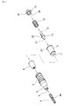
- FIG. 2 is an exploded perspective view thereof.
- the valve type writing instrument in accordance with the present invention includes an ink tank barrel 1; a valve housing cylinder 2, which is fitted into a tip end part of the ink tank barrel 1; a reduced-diameter part 3, which is integrally formed on the tip end side of the valve housing cylinder 2; a core 4, which is slidably supported by the reduced-diameter part 3, a tip end part thereof being protruded; and a cap (not shown).
- the core 4 side (the left side in these figures) is referred to as the tip end side or the top face side, while the side opposite thereto being referred to as the rear end side or the bottom face side.
- the core 4 is slidably supported, the peripheral surface thereof being surrounded by this core holding ribs 5.
- Each of the core holding ribs 5 is formed as a strip which is protruded to such an extent that it is lightly contacted with the core 4 for the purpose of holding the core 4 in a slidable manner.
- the core 4 can be adapted so as to be loaded after completion of the main body of the present valve type writing instrument.
- an ink reservoir member 6 which reservoirs the ink to be impregnated into the core 4, and a valve unit case 7, which is disposed on the rear side of the ink reservoir member 6, incorporating a valve mechanism.
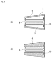
- the ink reservoir member 6 has a truncated cone-like shape, and a core insertion hole 8 is formed so as to be penetrated through the central portion thereof (especially see FIGS. 6(A) and 6(B) , and FIGS. 7(A) and 7(B) ) .
- this core insertion hole 8 one half part of the core 4 is slidably inserted (see FIGS. 3 and 4 ).
- the core insertion hole 8 is provided with the same diameter over the entire length thereof, however, the portion located behind the intermediate part may be provided with a slightly larger diameter ( FIG. 7 (A) ), or may be tapered ( FIG. 7 (B) ). Further, radially from the core insertion hole 8, a number of slits 9 for reservoiring the ink are formed.
- the bottom face of the ink reservoir member 6 is provided as a tapered face which is inwardly concaved toward the core insertion hole 8, such that, between the tapered face and the top face of the valve unit case 7, an ink reservoir space 10 for reservoiring the ink is formed.
- the valve unit case 7 has a top face opening 11 and a bottom face opening 12, and in the valve unit case 7, there are incorporated a valve element 14, which opens and closes the top face opening 11, and a return spring 15, which urges the valve element 14 so as to normally close the top face opening 11 (see FIGS. 3 and 4 ).
- the valve element 14 is shaped like a spinning top, having a tapered face 16, which provides a valve seat abutting part, and a top face side shaft 17, which is protruded from the tapered face 16, is projected from the top face opening 11 to face the inside of the core insertion hole 8 at the time of assembling.
- the valve element 14 is always pushed up by the return spring 15 at the time of no-load, the tapered face 16 being abutted against the inner edge of the top face opening 11, which serves as a valve seat, to thereby close the top face opening 11 (see FIG. 3 ), while, when the core 4 is pushed in against the pushing-up force of the return spring 15, thereby the valve element 14 being pressed by the core 4, the tapered face 16 thereof being separated from the inner edge of the top face opening 11, i.e., the valve seat, thereby the top face opening 11 being opened (see FIG. 4 ). With the top face opening 11 being thus opened, the ink, which has been stored in the valve unit case 7, flows out into the reservoir space 10 through the top face opening 11, and therefrom, flows in into the respective slits 9 to fill them.
- the bottom face opening 12 of the valve unit case 7 is closed by a cover member 18, which has an ink passage hole 19 for always introducing the ink in the ink tank barrel 1 into the inside of the valve unit case 7 (see FIGS. 3 and 4 ).
- a plurality of ink passage holes 19 are provided so as to surround a supporting cylinder 20, which is formed in the central portion of the cover member 18.
- the return spring 15 is supported with the upper end face thereof being abutted against a face on the rear side of the tapered face 16 of the valve element 14, and the lower end face being abutted against the cover member 18. Further, the bottom face-side shaft 21 of the valve element 14 is slidably inserted into the supporting cylinder 20 of the cover member 18.
- a plate-like stopper 22 is formed so as to be accommodated in the return spring 15. This plate-like stopper 22 is abutted against the cover member 18 (the top face of the supporting cylinder 20) when the core 4 being pushed in, thereby serving to regulate the pushing-in position of the core 4 (see FIGS. 2 , 3, and 4 ).
- valve unit case 7 The bottom face part of the valve unit case 7 is extended outward to form a flange 23, and the valve unit case 7 is inserted into the valve housing cylinder 2 until the flange 23 thereof is abutted against the lower end face of the valve housing cylinder 2, which, at the time of assembly, faces the inside of the ink tank barrel 1, thereby the position of insertion thereof into the valve housing cylinder 2 being defined. And, in that position, the top face of the valve unit case 7 is abutted against the bottom face of the ink reservoir member 6, with the top face opening 11 thereof communicating with the core holding hole 8 (the ink reservoir space 10) (see FIGS. 3 and 4 ).
- the ink which is delivered from the valve unit case 7 with the top face opening 11 of the valve unit case 7 being opened flows in into the respective slits 9 through the ink reservoir space 10, filling the ink reservoir space 10 and the respective slits 9.
- the ink which has filled the ink reservoir space 10 and the respective slits 9, directly permeates into the core 4, the lower half part thereof having been inserted into the ink reservoir member 6 to face the ink reservoir space 10 and the slits 9 over a wide range.
- the surplus ink is reservoired in the reservoir space 10 and the respective slits 9, and, as the ink impregnated in the core 4 is reduced with the writing, permeates into the core 4 as needed.
- the ink in the ink tank barrel 1 freely passes through the ink passage hole 19 in the cover member 18 by its own weight, flowing in into the valve unit case 7 to fill it.
- the ink, which has been introduced into the valve unit case 7, is kept reservoired there until the core 4 is pushed in into the valve housing cylinder 2, and the top face opening 11 is opened.
- the ink flows in into the ink reservoir member 6 ( FIG. 4 ) to fill the ink reservoir space 10 and the respective slits 9.
- the lower half part of the core 4 is accommodated in the core holding hole 8, which is surrounded by the ink reservoir space 10 and the respective slits 9, always reservoiring the ink, and can absorb the ink as needed, whereby the core 4 is prevented from being dried. Therefore, the need for frequently making a valve opening operation by pushing-in the core 4 is eliminated to thereby prevent occurrence of early damage of the core tip that is due to frequently making a valve opening operation. In addition, even if writing is performed at high speed, the ink rapidly permeates, thereby blurring of a written character being difficult to be caused.
- valve type writing instrument in accordance with the present invention provides a feature that it can be completed by taking the procedure constituted by loading the valve element 14 and the return spring 15 in the valve unit case 7; covering the valve unit case 7 with the cover member 18 to complete the valve mechanism part; housing this in the valve housing cylinder 2 together with the ink reservoir member 6; thereafter, inserting the core 4 from the reduced-diameter part 3 of the valve housing cylinder 2; and finally fitting the valve housing cylinder 2 in the ink tank barrel 1.
- the core 4 can also be finally inserted to be installed, and can be replaced with new one at any time.
- a stepped part 4a can be provided for the core 4 so as to be locked at the reduced-diameter part 3 of the valve housing cylinder 2 (see FIGS. 1 and 3 ).
Landscapes
- Pens And Brushes (AREA)
Applications Claiming Priority (1)
| Application Number | Priority Date | Filing Date | Title |
|---|---|---|---|
| PCT/JP2014/076839 WO2016056067A1 (ja) | 2014-10-07 | 2014-10-07 | 筆記具用インク貯留部材及びこれを用いたバルブ式筆記具 |
Publications (3)
| Publication Number | Publication Date |
|---|---|
| EP3025871A1 true EP3025871A1 (de) | 2016-06-01 |
| EP3025871A4 EP3025871A4 (de) | 2016-09-21 |
| EP3025871B1 EP3025871B1 (de) | 2019-09-04 |
Family
ID=55652730
Family Applications (1)
| Application Number | Title | Priority Date | Filing Date |
|---|---|---|---|
| EP14846766.5A Active EP3025871B1 (de) | 2014-10-07 | 2014-10-07 | Tintenbehälterelement für schreibinstrument und ventilartiges schreibinstrument damit |
Country Status (3)
| Country | Link |
|---|---|
| US (1) | US9950555B2 (de) |
| EP (1) | EP3025871B1 (de) |
| WO (1) | WO2016056067A1 (de) |
Cited By (1)
| Publication number | Priority date | Publication date | Assignee | Title |
|---|---|---|---|---|
| WO2018078462A1 (en) * | 2016-10-28 | 2018-05-03 | Jangir Ganesh Ram | Refillable writing instrument |
Families Citing this family (2)
| Publication number | Priority date | Publication date | Assignee | Title |
|---|---|---|---|---|
| CN108583062A (zh) * | 2018-05-29 | 2018-09-28 | 南浔善琏松柏湖笔厂 | 一种高吸墨量的新型毛笔及其制作方法 |
| USD921754S1 (en) * | 2019-06-20 | 2021-06-08 | Sanford, L.P. | Writing instrument |
Family Cites Families (22)
| Publication number | Priority date | Publication date | Assignee | Title |
|---|---|---|---|---|
| JPH055024Y2 (de) * | 1986-10-06 | 1993-02-09 | ||
| JP2594306Y2 (ja) | 1992-12-25 | 1999-04-26 | パイロットインキ株式会社 | 直液式筆記具 |
| ZA948098B (en) * | 1993-10-18 | 1995-06-05 | Gillette Co | Liquid ink |
| TW385760U (en) * | 1998-10-21 | 2000-03-21 | Mcaide Entpr Company Ltd | Pen |
| US6474893B1 (en) * | 1998-12-18 | 2002-11-05 | Mitsubishi Pencil Kabushiki Kaisha | Writing instrument having excellent cap-off performance |
| WO2002051648A1 (fr) * | 2000-12-26 | 2002-07-04 | Mitsubishi Pencil Kabushiki Kaisha | Marqueur pouvant rester longtemps decapuchonne |
| JP2002355602A (ja) * | 2001-05-31 | 2002-12-10 | Pentel Corp | 塗布具 |
| JP2003154785A (ja) * | 2001-11-26 | 2003-05-27 | Kotobuki:Kk | 直液式筆記具 |
| JP4318889B2 (ja) | 2002-05-14 | 2009-08-26 | エステー株式会社 | 揮散器 |
| JP4298968B2 (ja) * | 2002-06-19 | 2009-07-22 | 株式会社呉竹 | 筆記具 |
| MXPA06003051A (es) * | 2003-09-19 | 2006-06-20 | Sanford Lp | Marcadores destellantes de accion capilar y composiciones de tinta para ellos. |
| KR200366065Y1 (ko) * | 2004-08-04 | 2004-10-28 | 김병삼 | 액체성 s자형필기도구 |
| JP2008006668A (ja) | 2006-06-29 | 2008-01-17 | Mitsubishi Pencil Co Ltd | 直液式塗布具 |
| JP4919756B2 (ja) | 2006-10-04 | 2012-04-18 | 三菱鉛筆株式会社 | 筆記具 |
| JP2008155484A (ja) | 2006-12-22 | 2008-07-10 | Mitsubishi Pencil Co Ltd | マーキングペン |
| US20120009005A1 (en) * | 2008-04-15 | 2012-01-12 | Pawel Czubarow | Erasable ink for porous tip writing instruments |
| US8123424B2 (en) * | 2009-03-25 | 2012-02-28 | Lion Pencil Co., Ltd. | Ink feeder for felt-tip ink pen |
| US8485749B2 (en) * | 2009-07-20 | 2013-07-16 | Crayola Llc | Ink delivery systems |
| JP5608015B2 (ja) * | 2009-09-01 | 2014-10-15 | 三菱鉛筆株式会社 | 弁付塗布具 |
| US8092108B2 (en) * | 2009-12-30 | 2012-01-10 | Harry Bainbridge | Porous tip liquid applicator having draw fill mechanism |
| DE102010009694A1 (de) * | 2010-01-15 | 2011-07-21 | Georg LINZ GmbH & Co. KG, 90408 | Ventilmarker mit Verschlußfilm |
| JP5502844B2 (ja) * | 2011-12-14 | 2014-05-28 | 株式会社 エポックケミカル | バルブ式筆記具 |
-
2014
- 2014-10-07 WO PCT/JP2014/076839 patent/WO2016056067A1/ja not_active Ceased
- 2014-10-07 EP EP14846766.5A patent/EP3025871B1/de active Active
- 2014-10-07 US US14/646,830 patent/US9950555B2/en active Active
Cited By (3)
| Publication number | Priority date | Publication date | Assignee | Title |
|---|---|---|---|---|
| WO2018078462A1 (en) * | 2016-10-28 | 2018-05-03 | Jangir Ganesh Ram | Refillable writing instrument |
| CN109890624A (zh) * | 2016-10-28 | 2019-06-14 | G·R·詹吉尔 | 可再填充的书写工具 |
| US10889143B2 (en) | 2016-10-28 | 2021-01-12 | Ganesh Ram Jangir | Refillable writing instrument |
Also Published As
| Publication number | Publication date |
|---|---|
| EP3025871A4 (de) | 2016-09-21 |
| US9950555B2 (en) | 2018-04-24 |
| EP3025871B1 (de) | 2019-09-04 |
| WO2016056067A1 (ja) | 2016-04-14 |
| US20160257161A1 (en) | 2016-09-08 |
Similar Documents
| Publication | Publication Date | Title |
|---|---|---|
| US9688092B2 (en) | Refill for writing tool and writing tool | |
| EP3025871B1 (de) | Tintenbehälterelement für schreibinstrument und ventilartiges schreibinstrument damit | |
| HK1250503A1 (en) | Refill for writing tool and writing tool | |
| EP3208103B1 (de) | Tintenfüllvorrichtung | |
| US11186114B2 (en) | Direct liquid-type brush pen | |
| JP5998163B2 (ja) | バルブ式液材滲出具 | |
| JP7108287B2 (ja) | 水筆ペン | |
| US11745534B2 (en) | Writing utensil and producing method of writing utensil | |
| JP5502844B2 (ja) | バルブ式筆記具 | |
| JP6313734B2 (ja) | バルブ式液材滲出具 | |
| JP6748040B2 (ja) | バルブ式液材滲出具 | |
| JP7641031B2 (ja) | バルブ式液材滲出具 | |
| JP5729174B2 (ja) | 塗布具 | |
| JP6389649B2 (ja) | 筆記具 | |
| JP6374210B2 (ja) | 筆記具 | |
| DE202015102174U1 (de) | Nachfüllsystem für einen ein Fluid aufnehmenden Behälter | |
| JPH09290591A (ja) | 軸筒構造 | |
| JP5923637B2 (ja) | 筆記具用リフィル及び筆記具 | |
| JPH0885290A (ja) | 水性ボ−ルペンレフィル | |
| JP2010131097A (ja) | 塗布具 | |
| JP2008062605A (ja) | 液式筆記具及びその製造方法 | |
| JPH08108685A (ja) | バルブ装置付き液体筆記具 | |
| JPH0646979U (ja) | スライド栓付筆記具 | |
| JPH0649077U (ja) | バルブ栓付筆記具 |
Legal Events
| Date | Code | Title | Description |
|---|---|---|---|
| PUAI | Public reference made under article 153(3) epc to a published international application that has entered the european phase |
Free format text: ORIGINAL CODE: 0009012 |
|
| 17P | Request for examination filed |
Effective date: 20150401 |
|
| AK | Designated contracting states |
Kind code of ref document: A1 Designated state(s): AL AT BE BG CH CY CZ DE DK EE ES FI FR GB GR HR HU IE IS IT LI LT LU LV MC MK MT NL NO PL PT RO RS SE SI SK SM TR |
|
| AX | Request for extension of the european patent |
Extension state: BA ME |
|
| A4 | Supplementary search report drawn up and despatched |
Effective date: 20160824 |
|
| RIC1 | Information provided on ipc code assigned before grant |
Ipc: B43K 8/03 20060101ALI20160818BHEP Ipc: B43K 8/02 20060101AFI20160818BHEP |
|
| RIN1 | Information on inventor provided before grant (corrected) |
Inventor name: ODAKA, HARUO |
|
| STAA | Information on the status of an ep patent application or granted ep patent |
Free format text: STATUS: EXAMINATION IS IN PROGRESS |
|
| 17Q | First examination report despatched |
Effective date: 20171108 |
|
| DAX | Request for extension of the european patent (deleted) | ||
| REG | Reference to a national code |
Ref country code: DE Ref legal event code: R079 Ref document number: 602014053157 Country of ref document: DE Free format text: PREVIOUS MAIN CLASS: B43K0008020000 Ipc: B43K0008040000 |
|
| RIC1 | Information provided on ipc code assigned before grant |
Ipc: B43K 8/02 20060101ALI20190220BHEP Ipc: B43K 8/03 20060101ALI20190220BHEP Ipc: B43K 8/04 20060101AFI20190220BHEP |
|
| GRAP | Despatch of communication of intention to grant a patent |
Free format text: ORIGINAL CODE: EPIDOSNIGR1 |
|
| STAA | Information on the status of an ep patent application or granted ep patent |
Free format text: STATUS: GRANT OF PATENT IS INTENDED |
|
| INTG | Intention to grant announced |
Effective date: 20190403 |
|
| GRAS | Grant fee paid |
Free format text: ORIGINAL CODE: EPIDOSNIGR3 |
|
| GRAA | (expected) grant |
Free format text: ORIGINAL CODE: 0009210 |
|
| STAA | Information on the status of an ep patent application or granted ep patent |
Free format text: STATUS: THE PATENT HAS BEEN GRANTED |
|
| AK | Designated contracting states |
Kind code of ref document: B1 Designated state(s): AL AT BE BG CH CY CZ DE DK EE ES FI FR GB GR HR HU IE IS IT LI LT LU LV MC MK MT NL NO PL PT RO RS SE SI SK SM TR |
|
| REG | Reference to a national code |
Ref country code: GB Ref legal event code: FG4D |
|
| REG | Reference to a national code |
Ref country code: CH Ref legal event code: EP |
|
| REG | Reference to a national code |
Ref country code: AT Ref legal event code: REF Ref document number: 1174830 Country of ref document: AT Kind code of ref document: T Effective date: 20190915 |
|
| REG | Reference to a national code |
Ref country code: DE Ref legal event code: R096 Ref document number: 602014053157 Country of ref document: DE |
|
| REG | Reference to a national code |
Ref country code: IE Ref legal event code: FG4D |
|
| REG | Reference to a national code |
Ref country code: NL Ref legal event code: MP Effective date: 20190904 |
|
| REG | Reference to a national code |
Ref country code: LT Ref legal event code: MG4D |
|
| PG25 | Lapsed in a contracting state [announced via postgrant information from national office to epo] |
Ref country code: FI Free format text: LAPSE BECAUSE OF FAILURE TO SUBMIT A TRANSLATION OF THE DESCRIPTION OR TO PAY THE FEE WITHIN THE PRESCRIBED TIME-LIMIT Effective date: 20190904 Ref country code: LT Free format text: LAPSE BECAUSE OF FAILURE TO SUBMIT A TRANSLATION OF THE DESCRIPTION OR TO PAY THE FEE WITHIN THE PRESCRIBED TIME-LIMIT Effective date: 20190904 Ref country code: BG Free format text: LAPSE BECAUSE OF FAILURE TO SUBMIT A TRANSLATION OF THE DESCRIPTION OR TO PAY THE FEE WITHIN THE PRESCRIBED TIME-LIMIT Effective date: 20191204 Ref country code: NO Free format text: LAPSE BECAUSE OF FAILURE TO SUBMIT A TRANSLATION OF THE DESCRIPTION OR TO PAY THE FEE WITHIN THE PRESCRIBED TIME-LIMIT Effective date: 20191204 Ref country code: SE Free format text: LAPSE BECAUSE OF FAILURE TO SUBMIT A TRANSLATION OF THE DESCRIPTION OR TO PAY THE FEE WITHIN THE PRESCRIBED TIME-LIMIT Effective date: 20190904 Ref country code: HR Free format text: LAPSE BECAUSE OF FAILURE TO SUBMIT A TRANSLATION OF THE DESCRIPTION OR TO PAY THE FEE WITHIN THE PRESCRIBED TIME-LIMIT Effective date: 20190904 |
|
| PG25 | Lapsed in a contracting state [announced via postgrant information from national office to epo] |
Ref country code: LV Free format text: LAPSE BECAUSE OF FAILURE TO SUBMIT A TRANSLATION OF THE DESCRIPTION OR TO PAY THE FEE WITHIN THE PRESCRIBED TIME-LIMIT Effective date: 20190904 Ref country code: RS Free format text: LAPSE BECAUSE OF FAILURE TO SUBMIT A TRANSLATION OF THE DESCRIPTION OR TO PAY THE FEE WITHIN THE PRESCRIBED TIME-LIMIT Effective date: 20190904 Ref country code: GR Free format text: LAPSE BECAUSE OF FAILURE TO SUBMIT A TRANSLATION OF THE DESCRIPTION OR TO PAY THE FEE WITHIN THE PRESCRIBED TIME-LIMIT Effective date: 20191205 Ref country code: AL Free format text: LAPSE BECAUSE OF FAILURE TO SUBMIT A TRANSLATION OF THE DESCRIPTION OR TO PAY THE FEE WITHIN THE PRESCRIBED TIME-LIMIT Effective date: 20190904 Ref country code: ES Free format text: LAPSE BECAUSE OF FAILURE TO SUBMIT A TRANSLATION OF THE DESCRIPTION OR TO PAY THE FEE WITHIN THE PRESCRIBED TIME-LIMIT Effective date: 20190904 |
|
| REG | Reference to a national code |
Ref country code: AT Ref legal event code: MK05 Ref document number: 1174830 Country of ref document: AT Kind code of ref document: T Effective date: 20190904 |
|
| PG25 | Lapsed in a contracting state [announced via postgrant information from national office to epo] |
Ref country code: PL Free format text: LAPSE BECAUSE OF FAILURE TO SUBMIT A TRANSLATION OF THE DESCRIPTION OR TO PAY THE FEE WITHIN THE PRESCRIBED TIME-LIMIT Effective date: 20190904 Ref country code: AT Free format text: LAPSE BECAUSE OF FAILURE TO SUBMIT A TRANSLATION OF THE DESCRIPTION OR TO PAY THE FEE WITHIN THE PRESCRIBED TIME-LIMIT Effective date: 20190904 Ref country code: EE Free format text: LAPSE BECAUSE OF FAILURE TO SUBMIT A TRANSLATION OF THE DESCRIPTION OR TO PAY THE FEE WITHIN THE PRESCRIBED TIME-LIMIT Effective date: 20190904 Ref country code: PT Free format text: LAPSE BECAUSE OF FAILURE TO SUBMIT A TRANSLATION OF THE DESCRIPTION OR TO PAY THE FEE WITHIN THE PRESCRIBED TIME-LIMIT Effective date: 20200106 Ref country code: IT Free format text: LAPSE BECAUSE OF FAILURE TO SUBMIT A TRANSLATION OF THE DESCRIPTION OR TO PAY THE FEE WITHIN THE PRESCRIBED TIME-LIMIT Effective date: 20190904 Ref country code: RO Free format text: LAPSE BECAUSE OF FAILURE TO SUBMIT A TRANSLATION OF THE DESCRIPTION OR TO PAY THE FEE WITHIN THE PRESCRIBED TIME-LIMIT Effective date: 20190904 Ref country code: NL Free format text: LAPSE BECAUSE OF FAILURE TO SUBMIT A TRANSLATION OF THE DESCRIPTION OR TO PAY THE FEE WITHIN THE PRESCRIBED TIME-LIMIT Effective date: 20190904 |
|
| PG25 | Lapsed in a contracting state [announced via postgrant information from national office to epo] |
Ref country code: SM Free format text: LAPSE BECAUSE OF FAILURE TO SUBMIT A TRANSLATION OF THE DESCRIPTION OR TO PAY THE FEE WITHIN THE PRESCRIBED TIME-LIMIT Effective date: 20190904 Ref country code: SK Free format text: LAPSE BECAUSE OF FAILURE TO SUBMIT A TRANSLATION OF THE DESCRIPTION OR TO PAY THE FEE WITHIN THE PRESCRIBED TIME-LIMIT Effective date: 20190904 Ref country code: CZ Free format text: LAPSE BECAUSE OF FAILURE TO SUBMIT A TRANSLATION OF THE DESCRIPTION OR TO PAY THE FEE WITHIN THE PRESCRIBED TIME-LIMIT Effective date: 20190904 Ref country code: IS Free format text: LAPSE BECAUSE OF FAILURE TO SUBMIT A TRANSLATION OF THE DESCRIPTION OR TO PAY THE FEE WITHIN THE PRESCRIBED TIME-LIMIT Effective date: 20200224 |
|
| REG | Reference to a national code |
Ref country code: CH Ref legal event code: PL |
|
| REG | Reference to a national code |
Ref country code: DE Ref legal event code: R097 Ref document number: 602014053157 Country of ref document: DE |
|
| PLBE | No opposition filed within time limit |
Free format text: ORIGINAL CODE: 0009261 |
|
| STAA | Information on the status of an ep patent application or granted ep patent |
Free format text: STATUS: NO OPPOSITION FILED WITHIN TIME LIMIT |
|
| PG2D | Information on lapse in contracting state deleted |
Ref country code: IS |
|
| PG25 | Lapsed in a contracting state [announced via postgrant information from national office to epo] |
Ref country code: DK Free format text: LAPSE BECAUSE OF FAILURE TO SUBMIT A TRANSLATION OF THE DESCRIPTION OR TO PAY THE FEE WITHIN THE PRESCRIBED TIME-LIMIT Effective date: 20190904 Ref country code: LU Free format text: LAPSE BECAUSE OF NON-PAYMENT OF DUE FEES Effective date: 20191007 Ref country code: LI Free format text: LAPSE BECAUSE OF NON-PAYMENT OF DUE FEES Effective date: 20191031 Ref country code: CH Free format text: LAPSE BECAUSE OF NON-PAYMENT OF DUE FEES Effective date: 20191031 Ref country code: IS Free format text: LAPSE BECAUSE OF FAILURE TO SUBMIT A TRANSLATION OF THE DESCRIPTION OR TO PAY THE FEE WITHIN THE PRESCRIBED TIME-LIMIT Effective date: 20200105 |
|
| 26N | No opposition filed |
Effective date: 20200605 |
|
| REG | Reference to a national code |
Ref country code: BE Ref legal event code: MM Effective date: 20191031 |
|
| PG25 | Lapsed in a contracting state [announced via postgrant information from national office to epo] |
Ref country code: SI Free format text: LAPSE BECAUSE OF FAILURE TO SUBMIT A TRANSLATION OF THE DESCRIPTION OR TO PAY THE FEE WITHIN THE PRESCRIBED TIME-LIMIT Effective date: 20190904 Ref country code: BE Free format text: LAPSE BECAUSE OF NON-PAYMENT OF DUE FEES Effective date: 20191031 Ref country code: MC Free format text: LAPSE BECAUSE OF FAILURE TO SUBMIT A TRANSLATION OF THE DESCRIPTION OR TO PAY THE FEE WITHIN THE PRESCRIBED TIME-LIMIT Effective date: 20190904 |
|
| GBPC | Gb: european patent ceased through non-payment of renewal fee |
Effective date: 20191204 |
|
| PG25 | Lapsed in a contracting state [announced via postgrant information from national office to epo] |
Ref country code: FR Free format text: LAPSE BECAUSE OF NON-PAYMENT OF DUE FEES Effective date: 20191104 Ref country code: IE Free format text: LAPSE BECAUSE OF NON-PAYMENT OF DUE FEES Effective date: 20191007 Ref country code: GB Free format text: LAPSE BECAUSE OF NON-PAYMENT OF DUE FEES Effective date: 20191204 |
|
| PG25 | Lapsed in a contracting state [announced via postgrant information from national office to epo] |
Ref country code: CY Free format text: LAPSE BECAUSE OF FAILURE TO SUBMIT A TRANSLATION OF THE DESCRIPTION OR TO PAY THE FEE WITHIN THE PRESCRIBED TIME-LIMIT Effective date: 20190904 |
|
| PG25 | Lapsed in a contracting state [announced via postgrant information from national office to epo] |
Ref country code: HU Free format text: LAPSE BECAUSE OF FAILURE TO SUBMIT A TRANSLATION OF THE DESCRIPTION OR TO PAY THE FEE WITHIN THE PRESCRIBED TIME-LIMIT; INVALID AB INITIO Effective date: 20141007 Ref country code: MT Free format text: LAPSE BECAUSE OF FAILURE TO SUBMIT A TRANSLATION OF THE DESCRIPTION OR TO PAY THE FEE WITHIN THE PRESCRIBED TIME-LIMIT Effective date: 20190904 |
|
| PG25 | Lapsed in a contracting state [announced via postgrant information from national office to epo] |
Ref country code: TR Free format text: LAPSE BECAUSE OF FAILURE TO SUBMIT A TRANSLATION OF THE DESCRIPTION OR TO PAY THE FEE WITHIN THE PRESCRIBED TIME-LIMIT Effective date: 20190904 |
|
| PG25 | Lapsed in a contracting state [announced via postgrant information from national office to epo] |
Ref country code: MK Free format text: LAPSE BECAUSE OF FAILURE TO SUBMIT A TRANSLATION OF THE DESCRIPTION OR TO PAY THE FEE WITHIN THE PRESCRIBED TIME-LIMIT Effective date: 20190904 |
|
| PGFP | Annual fee paid to national office [announced via postgrant information from national office to epo] |
Ref country code: DE Payment date: 20251118 Year of fee payment: 12 |