EP4545864A1 - Verfahren und vorrichtung zur verwaltung von wärmeenergie für eine wohnanlage - Google Patents
Verfahren und vorrichtung zur verwaltung von wärmeenergie für eine wohnanlage Download PDFInfo
- Publication number
- EP4545864A1 EP4545864A1 EP24208378.0A EP24208378A EP4545864A1 EP 4545864 A1 EP4545864 A1 EP 4545864A1 EP 24208378 A EP24208378 A EP 24208378A EP 4545864 A1 EP4545864 A1 EP 4545864A1
- Authority
- EP
- European Patent Office
- Prior art keywords
- heat exchanger
- equipment
- thermodynamic
- heat
- circuit
- Prior art date
- Legal status (The legal status is an assumption and is not a legal conclusion. Google has not performed a legal analysis and makes no representation as to the accuracy of the status listed.)
- Pending
Links
Images
Classifications
-
- F—MECHANICAL ENGINEERING; LIGHTING; HEATING; WEAPONS; BLASTING
- F24—HEATING; RANGES; VENTILATING
- F24D—DOMESTIC- OR SPACE-HEATING SYSTEMS, e.g. CENTRAL HEATING SYSTEMS; DOMESTIC HOT-WATER SUPPLY SYSTEMS; ELEMENTS OR COMPONENTS THEREFOR
- F24D3/00—Hot-water central heating systems
- F24D3/08—Hot-water central heating systems in combination with systems for domestic hot-water supply
-
- E—FIXED CONSTRUCTIONS
- E04—BUILDING
- E04H—BUILDINGS OR LIKE STRUCTURES FOR PARTICULAR PURPOSES; SWIMMING OR SPLASH BATHS OR POOLS; MASTS; FENCING; TENTS OR CANOPIES, IN GENERAL
- E04H4/00—Swimming or splash baths or pools
- E04H4/12—Devices or arrangements for circulating water, i.e. devices for removal of polluted water, cleaning baths or for water treatment
- E04H4/129—Systems for heating the water content of swimming pools
-
- F—MECHANICAL ENGINEERING; LIGHTING; HEATING; WEAPONS; BLASTING
- F24—HEATING; RANGES; VENTILATING
- F24D—DOMESTIC- OR SPACE-HEATING SYSTEMS, e.g. CENTRAL HEATING SYSTEMS; DOMESTIC HOT-WATER SUPPLY SYSTEMS; ELEMENTS OR COMPONENTS THEREFOR
- F24D19/00—Details
- F24D19/10—Arrangement or mounting of control or safety devices
- F24D19/1006—Arrangement or mounting of control or safety devices for water heating systems
- F24D19/1009—Arrangement or mounting of control or safety devices for water heating systems for central heating
- F24D19/1039—Arrangement or mounting of control or safety devices for water heating systems for central heating the system uses a heat pump
-
- F—MECHANICAL ENGINEERING; LIGHTING; HEATING; WEAPONS; BLASTING
- F24—HEATING; RANGES; VENTILATING
- F24D—DOMESTIC- OR SPACE-HEATING SYSTEMS, e.g. CENTRAL HEATING SYSTEMS; DOMESTIC HOT-WATER SUPPLY SYSTEMS; ELEMENTS OR COMPONENTS THEREFOR
- F24D19/00—Details
- F24D19/10—Arrangement or mounting of control or safety devices
- F24D19/1006—Arrangement or mounting of control or safety devices for water heating systems
- F24D19/1066—Arrangement or mounting of control or safety devices for water heating systems for the combination of central heating and domestic hot water
- F24D19/1072—Arrangement or mounting of control or safety devices for water heating systems for the combination of central heating and domestic hot water the system uses a heat pump
-
- F—MECHANICAL ENGINEERING; LIGHTING; HEATING; WEAPONS; BLASTING
- F24—HEATING; RANGES; VENTILATING
- F24F—AIR-CONDITIONING; AIR-HUMIDIFICATION; VENTILATION; USE OF AIR CURRENTS FOR SCREENING
- F24F5/00—Air-conditioning systems or apparatus not covered by F24F1/00 or F24F3/00, e.g. using solar heat or combined with household units such as an oven or water heater
- F24F5/0096—Air-conditioning systems or apparatus not covered by F24F1/00 or F24F3/00, e.g. using solar heat or combined with household units such as an oven or water heater combined with domestic apparatus
-
- F—MECHANICAL ENGINEERING; LIGHTING; HEATING; WEAPONS; BLASTING
- F24—HEATING; RANGES; VENTILATING
- F24H—FLUID HEATERS, e.g. WATER OR AIR HEATERS, HAVING HEAT-GENERATING MEANS, e.g. HEAT PUMPS, IN GENERAL
- F24H1/00—Water heaters, e.g. boilers, continuous-flow heaters or water-storage heaters
- F24H1/54—Water heaters for bathtubs or pools; Water heaters for reheating the water in bathtubs or pools
-
- F—MECHANICAL ENGINEERING; LIGHTING; HEATING; WEAPONS; BLASTING
- F24—HEATING; RANGES; VENTILATING
- F24H—FLUID HEATERS, e.g. WATER OR AIR HEATERS, HAVING HEAT-GENERATING MEANS, e.g. HEAT PUMPS, IN GENERAL
- F24H15/00—Control of fluid heaters
- F24H15/20—Control of fluid heaters characterised by control inputs
- F24H15/254—Room temperature
-
- F—MECHANICAL ENGINEERING; LIGHTING; HEATING; WEAPONS; BLASTING
- F24—HEATING; RANGES; VENTILATING
- F24H—FLUID HEATERS, e.g. WATER OR AIR HEATERS, HAVING HEAT-GENERATING MEANS, e.g. HEAT PUMPS, IN GENERAL
- F24H15/00—Control of fluid heaters
- F24H15/30—Control of fluid heaters characterised by control outputs; characterised by the components to be controlled
- F24H15/375—Control of heat pumps
-
- F—MECHANICAL ENGINEERING; LIGHTING; HEATING; WEAPONS; BLASTING
- F24—HEATING; RANGES; VENTILATING
- F24D—DOMESTIC- OR SPACE-HEATING SYSTEMS, e.g. CENTRAL HEATING SYSTEMS; DOMESTIC HOT-WATER SUPPLY SYSTEMS; ELEMENTS OR COMPONENTS THEREFOR
- F24D15/00—Other domestic- or space-heating systems
- F24D15/04—Other domestic- or space-heating systems using heat pumps
-
- F—MECHANICAL ENGINEERING; LIGHTING; HEATING; WEAPONS; BLASTING
- F24—HEATING; RANGES; VENTILATING
- F24D—DOMESTIC- OR SPACE-HEATING SYSTEMS, e.g. CENTRAL HEATING SYSTEMS; DOMESTIC HOT-WATER SUPPLY SYSTEMS; ELEMENTS OR COMPONENTS THEREFOR
- F24D2200/00—Heat sources or energy sources
- F24D2200/11—Geothermal energy
-
- F—MECHANICAL ENGINEERING; LIGHTING; HEATING; WEAPONS; BLASTING
- F24—HEATING; RANGES; VENTILATING
- F24D—DOMESTIC- OR SPACE-HEATING SYSTEMS, e.g. CENTRAL HEATING SYSTEMS; DOMESTIC HOT-WATER SUPPLY SYSTEMS; ELEMENTS OR COMPONENTS THEREFOR
- F24D2200/00—Heat sources or energy sources
- F24D2200/12—Heat pump
Definitions
- the field of the invention relates to the management of thermal energy in a residential complex or similar, having identical needs, comprising at least one room and a pool.
- renewable energies hold great promise, particularly for producing heat or electricity.
- Renewable energies include wind power, solar power, biomass, hydropower, and geothermal energy. These energies offer numerous advantages, particularly in terms of resources and time availability, but also disadvantages in terms of costs and immediate availability. For example, wind and solar energy are only available depending on weather conditions, while other renewable energies have significant production costs that can influence their performance and therefore the benefits of their use.
- a solution often recommended today for heating a home is the air/water aerothermal heat pump, which captures calories in the air to heat a heat transfer fluid that will itself be used to heat the air in a house, for example using underfloor heating.
- This solution offers a very advantageous energy performance coefficient (COP) compared to a standard heating system, for example a standard electric heater.
- COP energy performance coefficient
- Geothermal heat pumps for example water/water type, have similar disadvantages, although often less marked due to greater consistency of the temperatures of the liquids in which the calories are captured, but generate much higher installation costs to draw water from aquifers or to create a surface network.
- Air-source or geothermal heat pumps can be reversible. They can capture heat from outside, in the air or in the ground, to heat a home or, conversely, capture heat from inside a home to cool it and release these heat outside, into the air, water or ground.
- Australian demand AU2013401842A1 describes a modular hydrothermal system comprising a primary circuit device, a secondary circuit device, a tertiary circuit device, an auxiliary device and a control device, in which the heat exchanges between the primary circuit and the tertiary circuit are ensured via the secondary circuit device.
- the control of the filtration assembly may aim at activating the filtration assembly in its entirety or in part, for example the activation of circulation means in said hydraulic circuit, for example the activation of a pump.
- the invention makes it possible in particular to optimize the management of the heating or air conditioning of a house by pooling certain resources, in particular relating to the circulation of water in existing installations, and/or using certain properties of existing installations, particularly in terms of heat storage capacity.
- said at least one heat exchanger is a first heat exchanger, the system further comprising a second heat exchanger for supplying or removing calories to the liquid circulating in said at least one hydraulic circuit.
- the first heat exchanger may be at least one radiator and/or underfloor heating
- the second heat exchanger may be a geothermal circuit.
- said at least one hydraulic circuit comprises at least one bypass element to allow the liquid circulating in said at least one hydraulic circuit to selectively circulate in said at least one basin or in said second heat exchanger.
- said at least one thermodynamic transfer equipment is a first thermodynamic transfer equipment, the system further comprising a second thermodynamic transfer equipment, the second thermodynamic transfer equipment being connected to said at least one heat exchanger by said at least one heat transfer fluid circuit.
- the first thermodynamic transfer equipment may be a water/water type heat pump
- the second thermodynamic transfer equipment may be an air/water type heat pump.
- said at least one thermodynamic transfer equipment comprises at least two distinct operating modes, including a first air/water operating mode and a second water/water operating mode.
- said at least one thermodynamic transfer equipment may be a hybrid air-water/air-water thermodynamic transfer pump.
- the system further comprises at least one domestic hot water heating device connected directly or indirectly to said at least one heat transfer liquid circuit.
- the system further comprises at least one fluid storage tank, said at least one storage tank being connected to said at least one heat transfer fluid circuit or to said at least one hydraulic circuit.
- the invention makes it possible in particular to optimize the management of the heating or air conditioning of a house by pooling certain resources, in particular relating to the circulation of water in existing installations, and/or by using certain properties of existing installations, in particular in terms of heat storage capacity.
- said at least one thermodynamic transfer equipment comprises at least two distinct operating modes, the method further comprising a step of estimating a heat transmission or evacuation efficiency of each of said at least two operating modes, said activation of said thermodynamic transfer equipment and said activation of said at least one filtration equipment comprising a step of selecting an operating mode, said selection being carried out as a function of said estimated efficiencies.
- said at least one thermodynamic transfer equipment is a first thermodynamic transfer equipment
- said assembly further comprising a second thermodynamic transfer equipment connected to said at least one heat exchanger by said at least one heat transfer fluid circuit
- the method further comprising a step of estimating a heat transmission or evacuation efficiency of said first and second thermodynamic transfer equipment, said activation of said first transfer equipment thermodynamics and said activation of said at least one filtration equipment being carried out according to said estimated efficiencies.
- said at least one heat exchanger is a first heat exchanger
- said system further comprises a second heat exchanger for supplying or removing calories to the liquid circulating in said at least one hydraulic circuit
- said at least one hydraulic circuit comprising at least one bypass element for allowing the liquid circulating in said at least one hydraulic circuit to circulate selectively in said at least one basin or in said second heat exchanger, the method comprising a step of selecting the circulation of the liquid circulating in said at least one hydraulic circuit in said at least one basin or in said second heat exchanger.
- said system further comprises at least one domestic hot water heating device connected to said at least one heat transfer liquid circuit, the method comprising an activation of said at least one thermodynamic transfer equipment and an activation of said at least one filtration equipment in response to a water heating command from said at least one domestic hot water heating device.
- a housing complex comprising in particular one or more rooms and one or more pools is considered to be a complex system that is managed as a whole (and not as a set of elementary systems managed independently). Managing a complex system as a whole makes it possible to optimize thermal energy management, limit energy discharges and exploit the characteristics of certain equipment for the benefit of other equipment.
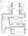
- FIG. 1 illustrates an example of a housing assembly comprising one or more premises 100, a thermodynamic transfer assembly 120 and a hydraulic assembly 140, according to embodiments of the invention.
- the premises 100 here comprise one or more heating equipment 102, for example radiators or underfloor heating, and one or more thermal regulation equipment 104, for example thermostats configured to transmit instructions for supplying or removing calories.
- the premises may comprise one or more domestic hot water production equipment 106 and/or one or more tanks 108 of a heat transfer liquid.
- the tank(s) 108 are preferably thermally insulated to limit heat exchanges with the outside.
- the premises further comprise a selection device, for example one or more controlled valves or solenoid valves 110-1, 110-2 and 110-3, for selecting one circuit loop or another, as described below.
- the thermodynamic transfer assembly 120 here comprises at least one circulation equipment 122 for a heat transfer liquid, for example a pump, and at least one first thermodynamic transfer equipment 124.
- the latter is configured to transfer calories from the first heat transfer liquid circulating in a first circuit to water circulating in a second circuit or vice versa (i.e., transfer calories from the water circulating in the second circuit to the heat transfer liquid).
- the heat transfer liquid is for example water to which treatment products or antifreeze can be added.
- the first thermodynamic transfer equipment is for example a water/water heat pump.
- the thermodynamic transfer assembly further comprises one (or more) second thermodynamic transfer equipment 126 allowing the transmission of calories from the heat transfer liquid circulating in the first circuit to the surrounding air.
- the second thermodynamic transfer equipment is for example an air/water heat pump. Still according to the illustrated example, the thermodynamic transfer assembly further comprises one or more heat exchangers 128 for evacuating calories from the water of the second circuit into the atmosphere or into a heat transfer liquid of a third circuit, for example a geothermal circuit, according to a simple heat exchange mechanism.
- the second thermodynamic transfer equipment and the heat exchanger are optional.
- the hydraulic assembly 140 comprises one or more basins 142, one or more filtration assemblies 144 comprising in particular a filter 146, for example a sand filter or a membrane filter, as well as water circulation equipment 148, for example a pump, in particular a filtration pump.
- the water circulation equipment may be a pump separate from one or more filtration assemblies.
- the hydraulic assembly 140 further comprises one or more water tanks 150, for example one or more water storage tanks, as well as a selection device, for example one or more controlled valves or solenoid valves 152-1 and 152-2, for selecting one circuit loop or another, as described below.
- a selection device for example one or more controlled valves or solenoid valves 152-1 and 152-2, for selecting one circuit loop or another, as described below.
- Pipe elements may be used to form the first and second circuits.
- the pipe elements 160-1 to 160-10 allow circulation of a heat transfer fluid between the first and second thermodynamic transfer equipment 124 and 126, the circulation equipment 122, the heating equipment(s) 102, the tank(s) 108 and/or the domestic hot water production equipment(s) 106 depending on the state of the selection device.
- the heat transfer liquid circulating in the first circuit formed by the pipe elements 160-1 to 160-8 makes it possible, for example, to supply calories to the heating equipment 102 and/or to the domestic hot water production equipment 106 or, on the contrary, to evacuate calories from the heating equipment 102 and/or from the domestic hot water production equipment 106. These calories are received from the first or second thermodynamic transfer equipment or evacuated to one of these equipments.
- calories received from the first or second thermodynamic transfer equipment can be transmitted to the heating equipment 102 and stored in the tank(s) 108 using the piping elements 160-1 to 160-5, 160-10 and 160-8 or transmitted to the domestic hot water production equipment 106 and stored in the tank(s) 108 using the piping elements 160-1 to 160-3, 160-9 and 160-6 to 160-8.
- calories received from the heating equipment 102 can be transmitted to the first or second thermodynamic transfer equipment using the piping elements 160-1 to 160-5, 160-10 and 160-8.
- the pipe elements 162-1 to 162-5 and 162-7 to 162-8 allow water to circulate between the first thermodynamic transfer equipment 124, the filtration assembly(s) 144, the basin(s) 142, the heat exchanger(s) 128 and, where appropriate, the reservoir(s) 150.
- the water circulating in the second circuit formed by the pipe elements 162-1 to 162-5 and 162-7 to 162-8 then makes it possible to capture calories from the basin(s) 142, the reservoir(s) 150 and/or the heat exchanger(s) 128 or, on the contrary, to supply calories to these elements.
- the pipe elements 162-1 to 162-3 and 162-6 to 162-8 allow water to circulate between the first thermodynamic transfer equipment 124, the filtration assembly(s) 144 and the heat exchanger(s) 128.
- the thermal regulation equipment(s) 104 make it possible to control the operation of the equipment illustrated in the Figure 1 to efficiently transfer calories.
- thermodynamic transfer equipment 124 and 126 can be merged into a single thermodynamic equipment integrating the air-water / thermodynamic pump / air-water exchangers.
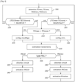
- FIG. 2 illustrates an example of steps for managing the heating or air conditioning of premises such as premises 100 of the Figure 1 .
- the steps illustrated on the Figure 2 can be implemented in thermal regulation equipment such as thermal regulation equipment 104 of the Figure 1 or in another device connected to such thermal regulation equipment.
- a first step (step 200) here aims to obtain a temperature of a room, noted TCmes, a target temperature (or temperature setpoint), noted TCcons, of the same room, a domestic hot water temperature, noted TECSmes, and a target temperature (or temperature setpoint), noted TECScons, of domestic hot water.
- a predetermined threshold noted SeuiIChauf. This threshold controls the triggering of the air conditioning or heating system.
- step 210 If the difference between the temperature of the room and the target temperature of this room, in absolute value, is greater than the predetermined threshold, it is then determined whether the room must be cooled or, on the contrary, heated, that is to say whether the temperature of the room is higher than the target temperature or whether it is lower than the target temperature (step 210).
- the air conditioning trigger threshold may be different from the heating trigger threshold.
- steps 205 and 210 may consist of a test to determine whether the difference between the temperature of the room and the corresponding target temperature is greater than a heating trigger threshold and a test to determine whether the difference between the target temperature of the room and its temperature is greater than an air conditioning trigger threshold.
- the air conditioning trigger threshold may be set to a value between 0.5 and 3°C, for example a value of 1°C (i.e., the air conditioning is triggered if the temperature of the room is at least one degree higher than the temperature
- the heating trigger threshold can be set to a value between 1 and 3°C, for example a value of 1.5°C (i.e., the heating is triggered if the room temperature is less than one and a half degrees below the desired temperature).
- thermodynamic transfer equipment(s) are configured in a heating mode (step 215). On the other hand, if the room is to be cooled, the thermodynamic transfer equipment(s) are configured in an air conditioning mode (step 220).
- thermodynamic transfer devices for example an air/water heat pump (denoted PACair ) and a water/water heat pump (denoted PACeau ) or a hybrid air-water/air-water thermodynamic transfer pump, or if certain thermodynamic transfer devices can be used according to several modes (e.g., air/water or water/water), an efficiency of each of the thermodynamic transfer devices that can be used and/or of each mode is estimated, for example on the basis of the air temperature and the temperature of the basins 142 and reservoirs 150 (step 225).
- the thermodynamic transfer device(s) and/or operating modes offering the best efficiencies are selected for use (step 230). For the sake of clarity, each operating mode of a thermodynamic device is considered, below, as a thermodynamic transfer device.
- thermodynamic transfer equipment(s) offering the best efficiencies do not include a water/water heat pump
- the circuit allowing the circulation of the heat transfer fluid is configured (step 235), for example by controlling the position of one or more solenoid valves.
- the thermodynamic transfer equipment(s) offering the best efficiencies are then activated (step 240) and the process continues at step 200.
- thermodynamic transfer equipment(s) offering the best efficiencies include at least one water/water heat pump
- the circuits allowing the circulation of the heat transfer fluids are configured (step 245), for example by controlling the position of one or more solenoid valves.
- the thermodynamic transfer equipment(s) offering the best efficiencies are then activated (step 250) as well as the filtration assembly or a part thereof (step 255), for example its water circulation pump. The process continues at step 200.
- step 255 If the difference between the domestic hot water temperature and the corresponding target temperature is greater than a threshold for triggering the domestic hot water heating (step 255), the process continues at step 215.
- the heat transfer fluid circulation circuit is preferably configured to allow simultaneous heating of the domestic hot water and the premises.
- the heat transfer fluid circulation circuit is preferably reconfigured to allow heating of the domestic hot water and cooling of the premises, sequentially.
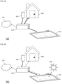
- FIG. 3 illustrates a simplified example of heat exchanges between the indoor air of a house (reference 300), domestic hot water (reference 305), the water of a swimming pool (reference 310) and the outdoor air (reference 315).
- These heat exchanges can in particular be carried out using a thermodynamic transfer assembly 320, as described with reference to figures 1 And 2 .
- the thin arrows represent a transfer of cold (i.e., a capture of calories) and the thick arrows represent a transfer of heat.
- FIG. 3a aims for heat exchanges during a period that can correspond to the months of May and September.
- calories are taken from the outside air (i.e., cold air is rejected outside) to heat the domestic hot water and/or the swimming pool water.
- the calories taken from the outside air can also be used to heat the air in rooms of the house or, conversely, calories can be taken from the house (i.e., cold air is rejected into the house to air-condition it) to heat the domestic hot water and/or the swimming pool water.
- FIG. 3b aims for heat exchanges at a time that could correspond to the month of June.
- calories are taken from the outside air (i.e., cold air is released outside) and from the air in the house (i.e., cold air is released into the house to air-condition it) to heat the domestic hot water and, depending on the weather conditions, the swimming pool water. If it is particularly hot, calories can be taken from the swimming pool water, for example at night after it has heated up during the day (as illustrated with sun 325), to heat the domestic hot water.
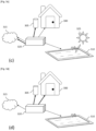
- FIG. 3c aims at heat exchanges at a period that could correspond to the months of July and August.
- calories are taken from the air of the house (i.e., cold air is rejected into the house to air-condition it) and from the water of the swimming pool, for example at night after it has heated up during the day (as illustrated with sun 325), to heat the domestic hot water.
- calories can be taken from the outside air (i.e., cold air is rejected outside) to heat the domestic hot water or calories can be taken from the air of the house (i.e., cold air is rejected into the house to air-condition it) and rejected into the outside air.
- There 3D figure aims for heat exchanges at a time that may correspond to the winter months.
- calories are taken from the outside air (i.e., cold air is rejected outside) to heat rooms in the house and/or domestic hot water.
- calories may be taken from the pool water, for example at night after it has heated during the day, to heat rooms in the house and/or domestic hot water.
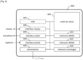
- FIG. 4 illustrates an example of a calculator capable of implementing a method according to particular embodiments of the invention, in particular the method illustrated in the Figure 2
- the 400 calculator can be integrated into an industrial regulator, a controller, an automaton or a PC type computer (acronym for personal computer in Anglo-Saxon terminology).
- the computer 400 further comprises, preferably, a communication interface 440 connected to a communication network, for example a wireless communication network and/or a local communication network, for example the Internet network, the interface being capable of transmitting and receiving data, in particular to or from another of the servers, computers, tablets and/or smartphones.
- a communication network for example a wireless communication network and/or a local communication network, for example the Internet network, the interface being capable of transmitting and receiving data, in particular to or from another of the servers, computers, tablets and/or smartphones.
- the computer 400 may also have a human-machine interface (HMI) 445, comprising for example a display or a touch display allowing a user to interact with programs implemented by the computer 400, and input means such as a keyboard and/or a mouse allowing a user to interact with programs implemented by the computer 400.
- HMI human-machine interface
- the communication bus allows communication and interoperability between the different elements included in the computer 400 or connected to it.
- the representation of the bus is not limiting and, in particular, the central processing unit is capable of communicating instructions to any element of the computer 400 directly or via another element of the computer 400.
- the executable code of the programs allowing the computer 400 to implement, in whole or in part, the method according to the invention, can be stored, for example, in the read-only memory 415.
- the executable code of the programs can be received via the communication network, via the interface 440, to be stored in a manner identical to that described previously. More generally, the program(s) can be loaded into one of the storage means of the computer 400 before being executed.
- the central processing unit 405 will control and direct the execution of the instructions or portions of software code of the program(s) according to the invention, instructions which are stored, for example, in the read-only memory 415 or in the other aforementioned storage elements.
- the program(s) which are stored in a non-volatile memory, for example the read-only memory 415 are transferred into the random access memory 410 which then contains the executable code of the program(s), as well as registers for storing the variables and parameters necessary for implementing the method according to the invention.
- the calculator 400 can be installed near a swimming pool or remotely, for example in a third-party facility responsible for pool maintenance. It can also be split into several elements, some of which can be installed near the swimming pool and others remotely. Similarly, part of the processing and/or calculations can be carried out in or near the sensors.
- person recognition can be carried out in a camera, the information being transmitted in addition to or instead of images to a pool control system.
- the artificial intelligence module can be implemented remotely and the expert system can be implemented locally.
- the proposed device, system and method include various variations, modifications and improvements which will be apparent to those skilled in the art, it being understood that these various variations, modifications and improvements are within the scope of the invention, as defined by the following claims.
- various aspects and features described above may be implemented together, or separately, or substituted for each other, and all of the various combinations and sub-combinations of the aspects and features are within the scope of the invention.
- some systems and equipment described above may not incorporate all of the modules and functions described for the preferred embodiments.
Landscapes
- Engineering & Computer Science (AREA)
- General Engineering & Computer Science (AREA)
- Chemical & Material Sciences (AREA)
- Combustion & Propulsion (AREA)
- Mechanical Engineering (AREA)
- Thermal Sciences (AREA)
- Physics & Mathematics (AREA)
- Sustainable Development (AREA)
- Life Sciences & Earth Sciences (AREA)
- Water Supply & Treatment (AREA)
- Architecture (AREA)
- Civil Engineering (AREA)
- Structural Engineering (AREA)
- Steam Or Hot-Water Central Heating Systems (AREA)
- Supply And Distribution Of Alternating Current (AREA)
Applications Claiming Priority (1)
| Application Number | Priority Date | Filing Date | Title |
|---|---|---|---|
| FR2311496A FR3154484B1 (fr) | 2023-10-23 | 2023-10-23 | Procédé et dispositif de gestion d’énergie thermique pour un ensemble d’habitation |
Publications (1)
| Publication Number | Publication Date |
|---|---|
| EP4545864A1 true EP4545864A1 (de) | 2025-04-30 |
Family
ID=89068940
Family Applications (1)
| Application Number | Title | Priority Date | Filing Date |
|---|---|---|---|
| EP24208378.0A Pending EP4545864A1 (de) | 2023-10-23 | 2024-10-23 | Verfahren und vorrichtung zur verwaltung von wärmeenergie für eine wohnanlage |
Country Status (2)
| Country | Link |
|---|---|
| EP (1) | EP4545864A1 (de) |
| FR (1) | FR3154484B1 (de) |
Citations (3)
| Publication number | Priority date | Publication date | Assignee | Title |
|---|---|---|---|---|
| US3926008A (en) * | 1974-08-15 | 1975-12-16 | Robert C Webber | Building cooling and pool heating system |
| WO2014068326A1 (en) * | 2012-11-02 | 2014-05-08 | Asd Enterprises Limited | Improvements to thermodynamic solar heat transfer systems |
| AU2013401842A1 (en) | 2013-09-24 | 2016-04-28 | Energen Chile S.A. | Modular hydrothermal system and method for the operation thereof |
-
2023
- 2023-10-23 FR FR2311496A patent/FR3154484B1/fr active Active
-
2024
- 2024-10-23 EP EP24208378.0A patent/EP4545864A1/de active Pending
Patent Citations (3)
| Publication number | Priority date | Publication date | Assignee | Title |
|---|---|---|---|---|
| US3926008A (en) * | 1974-08-15 | 1975-12-16 | Robert C Webber | Building cooling and pool heating system |
| WO2014068326A1 (en) * | 2012-11-02 | 2014-05-08 | Asd Enterprises Limited | Improvements to thermodynamic solar heat transfer systems |
| AU2013401842A1 (en) | 2013-09-24 | 2016-04-28 | Energen Chile S.A. | Modular hydrothermal system and method for the operation thereof |
Also Published As
| Publication number | Publication date |
|---|---|
| FR3154484B1 (fr) | 2026-02-06 |
| FR3154484A1 (fr) | 2025-04-25 |
Similar Documents
| Publication | Publication Date | Title |
|---|---|---|
| FR2921471A1 (fr) | Boitier repartiteur de fluide caloporteur, pour le couplage d'une pompe a chaleur a une pluralite de circuits de captage et de distribution de chaleur | |
| EP3111485B1 (de) | Hybrides system für supplementäre solarenergiegewinnung und -ableitung mit einer oder mehreren wärmepumpen | |
| EP2149760B1 (de) | System zur Stromversorgung und -steuerung für eine thermodynamische Vorrichtung | |
| US11974412B2 (en) | System and method for using waste heat generated by digital processing components | |
| EP2196743A2 (de) | Thermodynamische Vorrichtung mit Multi-Source-Multienergie-Heisswassertank | |
| US20150027659A1 (en) | Controllable variable inertia fluid heating and storage system | |
| EP4545864A1 (de) | Verfahren und vorrichtung zur verwaltung von wärmeenergie für eine wohnanlage | |
| CN111656098B (zh) | 用于能源网的改善的利用率的方法 | |
| EP2063191A1 (de) | Vorrichtung zur Steuerung einer Anlage zur Heizung und Erzeugung von Brauchwarmwasser | |
| EP3225937A1 (de) | Vorrichtung für gebäude, die ein speicherelement für ein thermisch wiederaufladbares fluid enthält | |
| EP4193095B1 (de) | Verfahren und anlagen zur bereitstellung von energie, insbesondere wärmeenergie, in mindestens einem gebäude oder dergleichen und zugehöriges system | |
| EP4028695B1 (de) | Sekundärsystem für ein niedrigtemperatur-wärmeenergieverteilungsnetz | |
| EP3152410A1 (de) | Anlage zur umwandlung von wärme in mechanische energie mit verbessertem system zur kühlung der arbeitsflüssigkeit | |
| EP3273170B1 (de) | Anlage zur heisswasserbereitung mit einem thermodynamischen schaltkreis, der über fotovoltaikzellen gespeist wird | |
| WO2013121361A2 (en) | Controllable variable inertia fluid heating and storage system | |
| EP4579572A1 (de) | Verfahren und vorrichtung zur energieverwaltung in einer komplexen umgebung einer wohnung | |
| FR2913755A1 (fr) | Dispositif de ventilation pour echangeur thermique | |
| FR2913757A1 (fr) | Dispositif de couplage d'un systeme de chauffage a liquide caloporteur a un dispositif de refroidissement | |
| US20240240830A1 (en) | System and method for using waste heat generated by digital processing components | |
| EP4624817A1 (de) | Optimierung der leistung eines heizsystems | |
| WO2019030637A2 (fr) | Dispositif de decouplage et d'hybridation d'energies renouvelables | |
| FR3133902A1 (fr) | Système de gestion d’énergie thermique pour réguler la température d’une structure | |
| EP3032180B1 (de) | Thermische Vorrichtung und Einsatzverfahren einer solchen Vorrichtung | |
| WO2009143933A2 (fr) | Systeme de chauffage solaire autonome et independant d'une autre source d'energie |
Legal Events
| Date | Code | Title | Description |
|---|---|---|---|
| PUAI | Public reference made under article 153(3) epc to a published international application that has entered the european phase |
Free format text: ORIGINAL CODE: 0009012 |
|
| STAA | Information on the status of an ep patent application or granted ep patent |
Free format text: STATUS: THE APPLICATION HAS BEEN PUBLISHED |
|
| AK | Designated contracting states |
Kind code of ref document: A1 Designated state(s): AL AT BE BG CH CY CZ DE DK EE ES FI FR GB GR HR HU IE IS IT LI LT LU LV MC ME MK MT NL NO PL PT RO RS SE SI SK SM TR |
|
| STAA | Information on the status of an ep patent application or granted ep patent |
Free format text: STATUS: REQUEST FOR EXAMINATION WAS MADE |
|
| 17P | Request for examination filed |
Effective date: 20251016 |