EP3034705A1 - Soupape de régulation de débit pour équipement de construction - Google Patents
Soupape de régulation de débit pour équipement de construction Download PDFInfo
- Publication number
- EP3034705A1 EP3034705A1 EP13891462.7A EP13891462A EP3034705A1 EP 3034705 A1 EP3034705 A1 EP 3034705A1 EP 13891462 A EP13891462 A EP 13891462A EP 3034705 A1 EP3034705 A1 EP 3034705A1
- Authority
- EP
- European Patent Office
- Prior art keywords
- valve
- orifice
- valve body
- hydraulic
- hydraulic fluid
- Prior art date
- Legal status (The legal status is an assumption and is not a legal conclusion. Google has not performed a legal analysis and makes no representation as to the accuracy of the status listed.)
- Withdrawn
Links
Images




Classifications
-
- F—MECHANICAL ENGINEERING; LIGHTING; HEATING; WEAPONS; BLASTING
- F15—FLUID-PRESSURE ACTUATORS; HYDRAULICS OR PNEUMATICS IN GENERAL
- F15B—SYSTEMS ACTING BY MEANS OF FLUIDS IN GENERAL; FLUID-PRESSURE ACTUATORS, e.g. SERVOMOTORS; DETAILS OF FLUID-PRESSURE SYSTEMS, NOT OTHERWISE PROVIDED FOR
- F15B13/00—Details of servomotor systems ; Valves for servomotor systems
- F15B13/02—Fluid distribution or supply devices characterised by their adaptation to the control of servomotors
- F15B13/04—Fluid distribution or supply devices characterised by their adaptation to the control of servomotors for use with a single servomotor
- F15B13/0416—Fluid distribution or supply devices characterised by their adaptation to the control of servomotors for use with a single servomotor with means or adapted for load sensing
- F15B13/0417—Load sensing elements; Internal fluid connections therefor; Anti-saturation or pressure-compensation valves
-
- E—FIXED CONSTRUCTIONS
- E02—HYDRAULIC ENGINEERING; FOUNDATIONS; SOIL SHIFTING
- E02F—DREDGING; SOIL-SHIFTING
- E02F9/00—Component parts of dredgers or soil-shifting machines, not restricted to one of the kinds covered by groups E02F3/00 - E02F7/00
- E02F9/20—Drives; Control devices
- E02F9/22—Hydraulic or pneumatic drives
- E02F9/2264—Arrangements or adaptations of elements for hydraulic drives
- E02F9/2267—Valves or distributors
-
- E—FIXED CONSTRUCTIONS
- E02—HYDRAULIC ENGINEERING; FOUNDATIONS; SOIL SHIFTING
- E02F—DREDGING; SOIL-SHIFTING
- E02F9/00—Component parts of dredgers or soil-shifting machines, not restricted to one of the kinds covered by groups E02F3/00 - E02F7/00
- E02F9/20—Drives; Control devices
- E02F9/22—Hydraulic or pneumatic drives
- E02F9/2278—Hydraulic circuits
- E02F9/2282—Systems using center bypass type changeover valves
-
- E—FIXED CONSTRUCTIONS
- E02—HYDRAULIC ENGINEERING; FOUNDATIONS; SOIL SHIFTING
- E02F—DREDGING; SOIL-SHIFTING
- E02F9/00—Component parts of dredgers or soil-shifting machines, not restricted to one of the kinds covered by groups E02F3/00 - E02F7/00
- E02F9/20—Drives; Control devices
- E02F9/22—Hydraulic or pneumatic drives
- E02F9/2278—Hydraulic circuits
- E02F9/2285—Pilot-operated systems
-
- E—FIXED CONSTRUCTIONS
- E02—HYDRAULIC ENGINEERING; FOUNDATIONS; SOIL SHIFTING
- E02F—DREDGING; SOIL-SHIFTING
- E02F9/00—Component parts of dredgers or soil-shifting machines, not restricted to one of the kinds covered by groups E02F3/00 - E02F7/00
- E02F9/20—Drives; Control devices
- E02F9/22—Hydraulic or pneumatic drives
- E02F9/2278—Hydraulic circuits
- E02F9/2292—Systems with two or more pumps
-
- E—FIXED CONSTRUCTIONS
- E02—HYDRAULIC ENGINEERING; FOUNDATIONS; SOIL SHIFTING
- E02F—DREDGING; SOIL-SHIFTING
- E02F9/00—Component parts of dredgers or soil-shifting machines, not restricted to one of the kinds covered by groups E02F3/00 - E02F7/00
- E02F9/20—Drives; Control devices
- E02F9/22—Hydraulic or pneumatic drives
- E02F9/2278—Hydraulic circuits
- E02F9/2296—Systems with a variable displacement pump
-
- F—MECHANICAL ENGINEERING; LIGHTING; HEATING; WEAPONS; BLASTING
- F16—ENGINEERING ELEMENTS AND UNITS; GENERAL MEASURES FOR PRODUCING AND MAINTAINING EFFECTIVE FUNCTIONING OF MACHINES OR INSTALLATIONS; THERMAL INSULATION IN GENERAL
- F16K—VALVES; TAPS; COCKS; ACTUATING-FLOATS; DEVICES FOR VENTING OR AERATING
- F16K11/00—Multiple-way valves, e.g. mixing valves; Pipe fittings incorporating such valves
- F16K11/02—Multiple-way valves, e.g. mixing valves; Pipe fittings incorporating such valves with all movable sealing faces moving as one unit
- F16K11/06—Multiple-way valves, e.g. mixing valves; Pipe fittings incorporating such valves with all movable sealing faces moving as one unit comprising only sliding valves, i.e. sliding closure elements
- F16K11/065—Multiple-way valves, e.g. mixing valves; Pipe fittings incorporating such valves with all movable sealing faces moving as one unit comprising only sliding valves, i.e. sliding closure elements with linearly sliding closure members
- F16K11/07—Multiple-way valves, e.g. mixing valves; Pipe fittings incorporating such valves with all movable sealing faces moving as one unit comprising only sliding valves, i.e. sliding closure elements with linearly sliding closure members with cylindrical slides
Definitions
- the present invention relates to a flow control valve for construction equipment. More particularly, the present invention relates to such a flow control valve for a construction machine in which in the case where a work apparatus or an attachment is operated to perform a combined operation during the traveling of the construction machine, a traveling apparatus and the work apparatus can be operated smoothly.
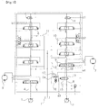
- a conventional hydraulic circuit for a construction machine in accordance with the prior art as shown in Fig. 1 includes:
- the pilot pressure a3 is applied to the straight traveling valve 13 (i.e., the pilot pressure a3 is applied only when the pilot pressure b1 or b2 for the work apparatus is applied simultaneously while the left and right switching valves 5 and 9 is shifted) to cause a spool of the straight traveling valve 13 to be shifted to the right on the drawing sheet.
- the pilot pressure b1 is applied to the switching valve 6 for the first work apparatus to cause a spool of the switching valve 6 to be shifted to the left on the drawing sheet
- the pilot pressure c1 is applied to a first center bypass valve 14 to cause a spool of the first center bypass valve 14 to be shifted to the left on the drawing sheet.
- the hydraulic fluid from the first hydraulic pump 1 is supplied to the left traveling motor 3 and the right traveling motor 7 to drive the left traveling motor 3 and the right traveling motor 7.
- some of the hydraulic fluid from the second hydraulic pump 2 is supplied to the switching valve 6 for the first work apparatus via the flow path 8, the straight traveling valve 13, and the flow path 11 so that a work apparatus such as an arm can be driven. Further, some of the hydraulic fluid from the second hydraulic pump 2 is supplied to the switching valve 10 for the second work apparatus through a flow path 12, and some of the hydraulic fluid from the second hydraulic pump 2 is supplied to the right traveling motor 7 via the flow path 16 and the switching valve 9.
- a flow control valve for a construction machine in accordance with the prior art as shown in Fig. 2 includes:
- An orifice 18 for allowing the hydraulic fluid to be supplied from the flow path 12 to the parallel path 26 is formed in the shape of an annular gap.
- the orifice 18 is formed as an annular gap between an outer circumferential surface of a poppet 19 and an inner circumferential surface of the valve body 20, which corresponds to the outer circumferential surface of the poppet 19.
- an inner diameter D1 of the valve body 20 is a fixed dimension, and thus an outer diameter D2 of the poppet 19, which corresponds to the inner diameter D1 of the valve body 20 is formed as largely as possible within a tolerance range.
- the outer diameter D2 of the poppet 19, which corresponds to the inner diameter D1 of the valve body 20 is set as a predetermined dimension so that a load is generated by a preset valve in the hydraulic fluid passing through the orifice 18, the amount of opening of the orifice 18 is decreased and thus the work apparatus can be operated.
- a noise is significantly generated.
- the conventional hydraulic circuit for a construction machine includes:
- the present invention has been made to solve the aforementioned problems occurring in the prior art, and it is an object of the present invention to provide a flow control valve for a construction machine in which in the case where a work apparatus or an attachment is operated to perform a combined operation during the traveling of the construction machine, it is prevented that a boom-up operation or an arm-out operation of the work apparatus is not performed or performed slowly, thereby preventing noise generation.
- a flow control valve for a construction machine including:
- the flow control valve may further include a first seal disposed between the valve body and the cover, and configured to prevent leakage of the hydraulic fluid through a gap between the valve body and the cover that comes into close contact with the valve body.
- the flow control valve may further include a second seal disposed between the first valve and the valve body and configured to prevent leakage of the hydraulic fluid through a gap between an outer circumferential surface of the first valve and an inner circumferential surface of the valve body, which corresponds to the outer circumferential surface of the first valve.
- the flow control valve may further include a third orifice formed at a predetermined position of the second valve in such a manner as to fluidically communicate with the second orifice of the first valve, and configured to prevent back pressure from being generated in the inside of the first valve when the first orifice is opened.
- the first valve may include:
- the second valve may include:
- the flow control valve for a construction machine in accordance with the present invention as constructed above has the following advantages.
- Fig. 4 is a schematic cross-sectional view showing a flow control valve for a construction machine in accordance with an embodiment of the present invention
- Fig. 5 is a schematic cross-sectional view showing a flow control valve for a construction machine in accordance with another embodiment of the present invention
- Figs. 6(a) and 6(b) are enlarged cross-sectional views showing a first valve and a second valve in a flow control valve for a construction machine in accordance with an embodiment of the present invention.
- a flow control valve for a construction machine in accordance with an embodiment of the present invention includes:
- the flow control valve further includes a first seal 32 disposed between the valve body 20 and the cover 31, and configured to prevent leakage of the hydraulic fluid through a gap between the valve body 20 and the cover 31 that comes into close contact with the valve body 20.
- the flow control valve further includes a second seal 33 disposed between the first valve 28 and the valve body 20 and configured to prevent leakage of the hydraulic fluid through a gap between an outer circumferential surface of the first valve 28 and an inner circumferential surface of the valve body 20, which corresponds to the outer circumferential surface of the first valve 28 as shown in Fig. 5 .
- the flow control valve further includes a third orifice 34 formed at a predetermined position of the second valve 29 in such a manner as to fluidically communicate with the second orifice 27 of the first valve 28, and configured to prevent back pressure from being generated in the inside of the first valve 28 when the first orifice 25 is opened.
- the first valve 28 includes:
- the second valve 29 includes:
- a non-explained reference numeral 35 denotes a fastening member for fastening the cover 31 to the valve body 20.
- a configuration of the flow control valve for a construction machine in accordance with an embodiment of the present as shown in Figs. 4 , 6(a) and 6(b) is the same as that of the conventional flow control valve for a construction machine as shown in Fig. 2 , except the first valve 28 installed in a path between the flow path 12 and the parallel path 26, the second valve 29 elastically supported by the elastic member 30 in the first valve 28, the cover 31, the first seal 32 configured to prevent leakage of the hydraulic fluid through a gap between the valve body 20 and the cover 31, and the second seal 33 configured to prevent leakage of the hydraulic fluid through a gap between the first valve 28 and the valve body 20.
- the detailed description of the same configuration and operation thereof will be omitted to avoid redundancy, and the same hydraulic parts are denoted by the same reference numerals.
- hydraulic fluid discharged from the second hydraulic pump 2 flows to the flow path 12, and then passes through the first orifice 25 of the first valve 28 to cause the second valve 29 in the first valve 28 to be lifted.
- the hydraulic fluid which has passed through the first orifice 25 flows to the parallel path 26 via the second orifice 27 fluidically communicating with the first orifice 25.
- the spool 23 installed in the valve body 20 is shifted to the left or right on the drawing sheet by the application of a pilot pressure Pi thereto.
- a pilot pressure Pi e.g., a right traveling motor
- the second seal 33 disposed on the outer circumferential surface of the first valve 28 can eliminate a gap between the outer circumferential surface of the first valve 28 having an outer diameter D2 and the inner circumferential surface of the valve body 20 having an inner diameter D1, which corresponds to the outer circumferential surface of the first valve 28.
- the first valve 28 is supported at one end thereof by the cover 31 to allow the stroke of the first valve 28 to be limited so that the first valve 28 can be prevented from being moved vertically. Resultantly, the hydraulic fluid can be prevented from leaking through the path between the flow path 12 and the parallel path 26.
- the hydraulic fluid supplied from the second hydraulic pump 2 to the flow path 12 can be supplied to the parallel path 26 only through the first orifice 25 and the second orifice 27.
- the flow control valve for a construction machine in accordance with an embodiment of the present invention as shown in Figs. 4 , 6(a) and 6(b) can solve a problem (i.e., occurrence of leakage of the hydraulic fluid through a gap of the path) associated with the conventional flow control valve for a construction machine as shown in Fig. 2 and a problem (i.e., an increase in the manufacturing cost due to addition of corresponding parts) associated in the conventional hydraulic circuit for a construction machine as shown in Fig. 3 .
- a problem i.e., occurrence of leakage of the hydraulic fluid through a gap of the path
- a problem i.e., an increase in the manufacturing cost due to addition of corresponding parts
Landscapes
- Engineering & Computer Science (AREA)
- General Engineering & Computer Science (AREA)
- Mining & Mineral Resources (AREA)
- Civil Engineering (AREA)
- Structural Engineering (AREA)
- Mechanical Engineering (AREA)
- Physics & Mathematics (AREA)
- Fluid Mechanics (AREA)
- Fluid-Pressure Circuits (AREA)
- Operation Control Of Excavators (AREA)
Applications Claiming Priority (1)
| Application Number | Priority Date | Filing Date | Title |
|---|---|---|---|
| PCT/KR2013/007270 WO2015023010A1 (fr) | 2013-08-13 | 2013-08-13 | Soupape de régulation de débit pour équipement de construction |
Publications (2)
| Publication Number | Publication Date |
|---|---|
| EP3034705A1 true EP3034705A1 (fr) | 2016-06-22 |
| EP3034705A4 EP3034705A4 (fr) | 2017-04-05 |
Family
ID=52468390
Family Applications (1)
| Application Number | Title | Priority Date | Filing Date |
|---|---|---|---|
| EP13891462.7A Withdrawn EP3034705A4 (fr) | 2013-08-13 | 2013-08-13 | Soupape de régulation de débit pour équipement de construction |
Country Status (5)
| Country | Link |
|---|---|
| US (1) | US20160201297A1 (fr) |
| EP (1) | EP3034705A4 (fr) |
| KR (1) | KR20160040581A (fr) |
| CN (1) | CN105637153A (fr) |
| WO (1) | WO2015023010A1 (fr) |
Families Citing this family (7)
| Publication number | Priority date | Publication date | Assignee | Title |
|---|---|---|---|---|
| EP3138964B1 (fr) | 2014-04-29 | 2019-09-11 | Volvo Construction Equipment AB | Soupape de régulation de débit destinée à un équipement de construction |
| EP3201475B1 (fr) * | 2014-09-29 | 2018-12-19 | Parker Hannifin Corporation | Vanne à plusieurs voies |
| JP6440451B2 (ja) * | 2014-10-27 | 2018-12-19 | Kyb株式会社 | ロードセンシングバルブ装置 |
| JP6717541B2 (ja) * | 2016-07-28 | 2020-07-01 | キャタピラー エス エー アール エル | 弁装置およびこれを備えた流体圧システム |
| US11603645B2 (en) * | 2017-11-08 | 2023-03-14 | Volvo Construction Equipment Ab | Hydraulic circuit |
| CN110173015B (zh) * | 2019-05-28 | 2021-07-30 | 江苏徐工工程机械研究院有限公司 | 直线行走阀、工程机械液压控制系统和工程机械 |
| US12448955B2 (en) * | 2021-02-16 | 2025-10-21 | Parker-Hannifin Corporation | Displacement control for hydraulic pump |
Family Cites Families (30)
| Publication number | Priority date | Publication date | Assignee | Title |
|---|---|---|---|---|
| GB1033109A (en) * | 1963-07-19 | 1966-06-15 | Dowty Hydraulic Units Ltd | Control valves for fluid-pressure-operated mechanisms |
| US3501673A (en) * | 1968-04-29 | 1970-03-17 | Stromberg Datagraphix Inc | Variable magnification cathode ray tube |
| US3534774A (en) * | 1968-11-14 | 1970-10-20 | Koehring Co | Pressure compensated control valve |
| US3901264A (en) * | 1972-03-06 | 1975-08-26 | Gresen Manufacturing Co | Adjustable flow control for hydraulic valves having high pressure main supply and controls fluid flow to cylinder and exhaust ports |
| US3774635A (en) * | 1972-04-18 | 1973-11-27 | Sperry Rand Corp | Power transmission |
| FR2194891B1 (fr) * | 1972-08-03 | 1976-01-23 | Poclain Fr | |
| US3985153A (en) * | 1974-08-28 | 1976-10-12 | Tomco, Inc. | Pressure compensating valve spool assembly for a hydraulic control valve |
| US4574839A (en) * | 1984-04-19 | 1986-03-11 | J. I. Case Company | Directional control valve with integral flow control valve |
| DE3619927A1 (de) * | 1986-06-13 | 1987-12-23 | Rexroth Mannesmann Gmbh | 2-wege-einbauventil |
| JPH0786361B2 (ja) * | 1988-11-10 | 1995-09-20 | 株式会社ゼクセル | 油圧制御弁 |
| DE4005967C2 (de) * | 1990-02-26 | 1996-05-09 | Rexroth Mannesmann Gmbh | Steueranordnung für mehrere hydraulische Verbraucher |
| JPH0758082B2 (ja) * | 1990-06-22 | 1995-06-21 | 株式会社ゼクセル | 油圧制御弁装置 |
| KR0145143B1 (ko) * | 1992-10-29 | 1998-08-01 | 오까다 하지메 | 유압제어밸브장치 및 유압구동장치 |
| LU88384A1 (de) * | 1993-07-16 | 1995-02-01 | Hydrolux Sarl | 2-Wege-Einbauventil als Sitzventil |
| JPH07279906A (ja) * | 1994-03-31 | 1995-10-27 | Kayaba Ind Co Ltd | 油圧制御装置 |
| KR100348128B1 (ko) * | 1994-09-30 | 2002-11-22 | 볼보 컨스트럭션 이키프먼트 홀딩 스웨덴 에이비 | 가변우선기능을갖는콘트롤밸브 |
| KR100208732B1 (ko) * | 1996-05-21 | 1999-07-15 | 토니헬샴 | 가변 재생기능이 구비된 중장비용 콘트롤밸브 |
| US5791142A (en) * | 1997-03-27 | 1998-08-11 | Husco International, Inc. | Hydraulic control valve system with split pressure compensator |
| US5890362A (en) * | 1997-10-23 | 1999-04-06 | Husco International, Inc. | Hydraulic control valve system with non-shuttle pressure compensator |
| JP3536243B2 (ja) * | 1998-03-16 | 2004-06-07 | 油研工業株式会社 | 油圧供給装置 |
| KR100631064B1 (ko) * | 2001-12-21 | 2006-10-02 | 볼보 컨스트럭션 이키프먼트 홀딩 스웨덴 에이비 | 건설중장비용 유량 가변제어장치 |
| US6745564B2 (en) * | 2001-12-21 | 2004-06-08 | Volvo Construction Equipment Holding Sweden Ab | Hydraulic variable control apparatus for heavy construction equipment |
| US6868672B2 (en) * | 2003-05-13 | 2005-03-22 | Sauer-Danfoss, Inc. | Method of controlling a swinging boom and apparatus for controlling the same |
| KR100518767B1 (ko) * | 2003-05-28 | 2005-10-06 | 볼보 컨스트럭션 이키프먼트 홀딩 스웨덴 에이비 | 건설중장비용 액츄에이터 유량 가변제어장치 |
| KR100611713B1 (ko) * | 2004-10-14 | 2006-08-11 | 볼보 컨스트럭션 이키프먼트 홀딩 스웨덴 에이비 | 재생기능을 구비한 유압제어밸브 |
| US7549241B2 (en) * | 2005-07-07 | 2009-06-23 | Nabtesco Corporation | Hydraulic control device for loader |
| KR100753990B1 (ko) * | 2006-08-29 | 2007-08-31 | 볼보 컨스트럭션 이키프먼트 홀딩 스웨덴 에이비 | 주행직진용 유압회로 |
| JP4782711B2 (ja) * | 2007-02-21 | 2011-09-28 | 日立建機株式会社 | 方向制御弁装置およびこの方向制御弁装置を複数備えた方向制御弁装置ブロック |
| US7621211B2 (en) * | 2007-05-31 | 2009-11-24 | Caterpillar Inc. | Force feedback poppet valve having an integrated pressure compensator |
| WO2011096001A1 (fr) * | 2010-02-02 | 2011-08-11 | Bucher Hydraulics S.P.A. | Section hydraulique pour applications de détection de charge et distributeur hydraulique multiple |
-
2013
- 2013-08-13 KR KR1020167003724A patent/KR20160040581A/ko not_active Ceased
- 2013-08-13 EP EP13891462.7A patent/EP3034705A4/fr not_active Withdrawn
- 2013-08-13 US US14/911,843 patent/US20160201297A1/en not_active Abandoned
- 2013-08-13 WO PCT/KR2013/007270 patent/WO2015023010A1/fr not_active Ceased
- 2013-08-13 CN CN201380080199.7A patent/CN105637153A/zh active Pending
Also Published As
| Publication number | Publication date |
|---|---|
| KR20160040581A (ko) | 2016-04-14 |
| WO2015023010A1 (fr) | 2015-02-19 |
| US20160201297A1 (en) | 2016-07-14 |
| EP3034705A4 (fr) | 2017-04-05 |
| CN105637153A (zh) | 2016-06-01 |
Similar Documents
| Publication | Publication Date | Title |
|---|---|---|
| EP3034705A1 (fr) | Soupape de régulation de débit pour équipement de construction | |
| EP2573282B1 (fr) | Vanne de régulation de pression hydraulique pour matériel de construction | |
| EP2876306B1 (fr) | Soupape de limitation de débit destinée à des engins de chantier | |
| CN103410803B (zh) | 液控换向阀、联动控制液压系统与挖掘机的液压控制系统 | |
| JP2009103304A (ja) | 建設機械用油圧制御弁 | |
| CN103221696A (zh) | 用于施工机械的流量控制阀 | |
| CN105705706B (zh) | 用于具有浮动功能的工程设备的流量控制阀 | |
| US20070290151A1 (en) | Valve | |
| CN109487838B (zh) | 液压回路 | |
| KR20080085273A (ko) | 주행중 버킷의 버킷레스트 이탈방지용 유압회로 | |
| CN203248431U (zh) | 一种卸荷阀及液压油缸回油背压卸荷装置和工程机械 | |
| US9222594B2 (en) | Directional valve equipped with pressure control | |
| KR101596379B1 (ko) | 유량 증폭기의 자동왕복 유량조절 제어 기구 | |
| US20140345268A1 (en) | Travel control system for construction machinery | |
| JP5283862B2 (ja) | 油圧制御装置 | |
| CN108026942A (zh) | 阀装置 | |
| CN209838811U (zh) | 具有工作片内卸荷与回油逻辑功能的多路阀 | |
| KR100816661B1 (ko) | 에너지 절감형 유압회로 | |
| JP4159837B2 (ja) | ガスケット | |
| CN114623121B (zh) | 电控多路阀 | |
| JP2019060439A (ja) | 液圧駆動装置 | |
| CN101356394B (zh) | 转换阀 | |
| JP5105845B2 (ja) | 油圧制御装置 | |
| KR20220149236A (ko) | 유압 밸브 및 농업용 트랙터 프론트 로더의 유압 제어장치 | |
| JP4558451B2 (ja) | 弁装置 |
Legal Events
| Date | Code | Title | Description |
|---|---|---|---|
| PUAI | Public reference made under article 153(3) epc to a published international application that has entered the european phase |
Free format text: ORIGINAL CODE: 0009012 |
|
| 17P | Request for examination filed |
Effective date: 20160212 |
|
| AK | Designated contracting states |
Kind code of ref document: A1 Designated state(s): AL AT BE BG CH CY CZ DE DK EE ES FI FR GB GR HR HU IE IS IT LI LT LU LV MC MK MT NL NO PL PT RO RS SE SI SK SM TR |
|
| AX | Request for extension of the european patent |
Extension state: BA ME |
|
| DAX | Request for extension of the european patent (deleted) | ||
| A4 | Supplementary search report drawn up and despatched |
Effective date: 20170307 |
|
| RIC1 | Information provided on ipc code assigned before grant |
Ipc: E02F 9/22 20060101AFI20170301BHEP Ipc: F15B 13/04 20060101ALI20170301BHEP Ipc: F16K 11/07 20060101ALI20170301BHEP Ipc: F15B 13/043 20060101ALI20170301BHEP |
|
| STAA | Information on the status of an ep patent application or granted ep patent |
Free format text: STATUS: THE APPLICATION IS DEEMED TO BE WITHDRAWN |
|
| 18D | Application deemed to be withdrawn |
Effective date: 20171005 |