EP3034732B1 - Installation de porte battante pliante - Google Patents
Installation de porte battante pliante Download PDFInfo
- Publication number
- EP3034732B1 EP3034732B1 EP14198616.6A EP14198616A EP3034732B1 EP 3034732 B1 EP3034732 B1 EP 3034732B1 EP 14198616 A EP14198616 A EP 14198616A EP 3034732 B1 EP3034732 B1 EP 3034732B1
- Authority
- EP
- European Patent Office
- Prior art keywords
- frame
- folding
- hinge body
- door
- hinge
- Prior art date
- Legal status (The legal status is an assumption and is not a legal conclusion. Google has not performed a legal analysis and makes no representation as to the accuracy of the status listed.)
- Active
Links
Images






Classifications
-
- E—FIXED CONSTRUCTIONS
- E05—LOCKS; KEYS; WINDOW OR DOOR FITTINGS; SAFES
- E05D—HINGES OR SUSPENSION DEVICES FOR DOORS, WINDOWS OR WINGS
- E05D15/00—Suspension arrangements for wings
- E05D15/26—Suspension arrangements for wings for folding wings
-
- E—FIXED CONSTRUCTIONS
- E05—LOCKS; KEYS; WINDOW OR DOOR FITTINGS; SAFES
- E05D—HINGES OR SUSPENSION DEVICES FOR DOORS, WINDOWS OR WINGS
- E05D5/00—Construction of single parts, e.g. the parts for attachment
- E05D5/02—Parts for attachment, e.g. flaps
- E05D5/0215—Parts for attachment, e.g. flaps for attachment to profile members or the like
- E05D5/0223—Parts for attachment, e.g. flaps for attachment to profile members or the like with parts, e.g. screws, extending through the profile wall or engaging profile grooves
- E05D5/0238—Parts for attachment, e.g. flaps for attachment to profile members or the like with parts, e.g. screws, extending through the profile wall or engaging profile grooves with parts engaging profile grooves
-
- E—FIXED CONSTRUCTIONS
- E06—DOORS, WINDOWS, SHUTTERS, OR ROLLER BLINDS IN GENERAL; LADDERS
- E06B—FIXED OR MOVABLE CLOSURES FOR OPENINGS IN BUILDINGS, VEHICLES, FENCES OR LIKE ENCLOSURES IN GENERAL, e.g. DOORS, WINDOWS, BLINDS, GATES
- E06B3/00—Window sashes, door leaves, or like elements for closing wall or like openings; Layout of fixed or moving closures, e.g. windows in wall or like openings; Features of rigidly-mounted outer frames relating to the mounting of wing frames
- E06B3/32—Arrangements of wings characterised by the manner of movement; Arrangements of movable wings in openings; Features of wings or frames relating solely to the manner of movement of the wing
- E06B3/48—Wings connected at their edges, e.g. foldable wings
- E06B3/481—Wings foldable in a zig-zag manner or bi-fold wings
-
- E—FIXED CONSTRUCTIONS
- E06—DOORS, WINDOWS, SHUTTERS, OR ROLLER BLINDS IN GENERAL; LADDERS
- E06B—FIXED OR MOVABLE CLOSURES FOR OPENINGS IN BUILDINGS, VEHICLES, FENCES OR LIKE ENCLOSURES IN GENERAL, e.g. DOORS, WINDOWS, BLINDS, GATES
- E06B3/00—Window sashes, door leaves, or like elements for closing wall or like openings; Layout of fixed or moving closures, e.g. windows in wall or like openings; Features of rigidly-mounted outer frames relating to the mounting of wing frames
- E06B3/70—Door leaves
- E06B2003/7059—Specific frame characteristics
- E06B2003/7074—Metal frames
- E06B2003/7076—Metal frames insulated
Definitions
- the present invention relates to a folding door system.
- the invention relates to a folding door system in which the door leaves can be preassembled independently of a connecting hinge.
- a folding panel system comprises at least one folding panel door, which in turn has at least two panels.
- hinges are used, which are mostly attached to the narrow side of the wings. In this way, however, a cold bridge is created between the outer surfaces of the door leaves, so that the door leaves can no longer be used as thermal insulation between two areas.
- the wings cannot be pre-assembled; rather, the hinge has to be installed when the wing is installed.
- the leaves are only for the folding door system and cannot be used flexibly.
- a folding door system according to the preamble of claim 1 is also from FR 2 638 778 A1 known.
- a folding door system that has at least one Comprises folding wing door with at least two wings and a hinge body arranged therebetween.
- Each wing comprises a frame, the frame having a groove into which a fastening web of the hinge body can be inserted.
- Both the groove and the fastening web have an undercut, so that there is a form-fitting connection between the frame and the hinge body.
- the form fit acts preferably in the horizontal direction, so that there is no form fit in the vertical direction.
- the groove preferably extends in the vertical direction, so that the hinge body can be inserted into the groove via the vertical direction.
- the hinge body This enables the hinge body to be inserted at a later date, which means that the sash can be pre-assembled.
- the door leaf can thus be used for various applications and does not initially have to be manufactured for a folding door system.
- this enables a flexible construction of the hinge, since only the fastening web has to be present in order to attach the hinge body to the wing. Otherwise, the hinge body is not restricted in its geometry.
- the undercut allows a very simple fixation in the horizontal direction.
- the object is also achieved by a method for producing a folding door system.
- the method relates in particular to the folding door system described above.
- the method comprises the following steps: First, a frame is provided, the frame having a groove. A filling element, in particular a pane of glass, is then inserted into the frame. Finally, a wing is created by attaching at least one hinge body to the frame.
- a fastening web of the hinge body is inserted into the groove of the frame, wherein the groove and the fastening web have an undercut, so that a positive connection is present between the frame and the hinge body.
- the hinge body has a bar web.
- the bar web can be connected to the frame. In this way, fixation is also advantageously created in the vertical direction, so that the hinge body is fully fixed to the frame.
- the bar web has at least one threaded hole.
- the bar web particularly advantageously has a large number of such threaded bores.
- a fastening bolt in particular a grub screw, can be screwed into the threaded hole and pressed against the frame.
- the bar web is advantageously arranged opposite the undercut, so that the undercuts of the fastening web and groove are simultaneously pressed against the frame by pressing the fastening bolt.
- There is a very simple assembly by means of a frictional connection which does not require any additional components, such as in particular drilled holes or nuts. Rather, the undercut of the groove is clamped between the fastening web and the fastening bolt, which is screwed into the threaded hole of the bar web. The resulting frictional connection allows a connection in all directions.
- the folding wing door system comprises at least one first wing with a first frame and at least one second wing with a second frame.
- a first hinge body is arranged on the first frame, while a second hinge body is arranged on the second frame.
- the first hinge body can be mounted on at least two second hinge bodies, while the second hinge body can be mounted on at least two first hinge bodies.
- a modular structure of the hinge which is composed of at least one first hinge body and at least one second hinge body, is given. Any number of hinge bodies can be used, as they can be connected to one another as often as required.
- a load capacity and a stability of the connection between the first wing and the second wing are given by a number of first hinge bodies and second hinge bodies. If the number of first hinge bodies and second hinge bodies is increased, the result is a more stable and stiffer connection, which in particular prevents the folding doors from being lowered during an opening process or a closing process.
- the first hinge body and the second hinge body are advantageously rotatably mounted on one another.
- the first hinge body is rotatably mounted on the second hinge body.
- first hinge body has a first sleeve-shaped area and the second hinge body has a second sleeve-shaped area.
- the first sleeve-shaped area is mounted on the second sleeve-shaped area via a mounted door bolt, this mounting in particular by an arrangement of the first sleeve-shaped area and the vertically stacked one above the other second sleeve-shaped area is reached.
- the door bolt only has one short length of the first sleeve-shaped portion and the second sleeve-shaped portion extends.
- the door bolt extends over a maximum of 10% of the length of the first sleeve-shaped region and the second sleeve-shaped region, particularly advantageously over less than 5%.
- the door bolt is advantageously mounted on the sleeve-shaped areas via ball bearings, in particular via closed ball bearings. In this way, a very simple but nevertheless effective and stable mounting of the first hinge body on the second hinge body is given.
- a sum of the lengths of the first hinge body and the second hinge body corresponds at most to the entire height and at least between 85% and 95% of the height of the first door leaf or the second door leaf.
- the sum of the lengths of the first hinge body and the second hinge body corresponds to a minimum of between 88% and 93% of the height of the first door leaf or the second door leaf. It is provided that a length of the first hinge body or the second hinge body is a dimension in the vertical direction. Likewise, the height of the first door leaf or the second door leaf is a dimension in the horizontal direction. This means that the door is supported in a very stable and robust manner.
- the groove is advantageously arranged in a vertical profile element of the frame.
- the groove is oriented vertically. This allows the first hinge body and the second hinge body to be attached to the first frame and the second frame by being pushed into the groove in the vertical direction.
- the entire height of the door leaf serves as a holder for the first hinge body and the second hinge body, as a result of which this is fastened very stably to the first frame and the second frame.
- the broad side used for assembly in the prior art i.e. H. the thickness of the frame, is not used for assembling the first hinge body and the second hinge body. This enables a more stable connection than in the prior art.
- the groove is advantageously arranged in an outer edge region of the profile element of the frame. It is provided that the outer edge area extends from an outer surface up to a maximum of a third, preferably up to a maximum of a quarter, of the thickness of the profile element into the profile element.
- the thickness of the profile element is measured in particular perpendicular to the frame plane and thus perpendicular to the travel path of the folding wing doors, which means that the thickness is measured parallel to the folding direction of the folding wing doors.
- the attachment in the edge area therefore does not create a cold bridge across the thickness of the frame. If the frame itself is thermally separated over the thickness, this thermal separation is not adversely affected by the attachment of the first hinge element and the second hinge element. Rather, the thermal separation is supported by the design of the first hinge body and the second hinge body.
- a folding door system which comprises at least one folding door with at least two leaves.
- Each wing has a frame, the frame comprising at least one horizontal profile element and at least one vertical profile element.
- the vertical profile element has at least one fastening groove into which a fastening element can be inserted.
- the horizontal profile element and the vertical profile element are connected via the fastening element.
- the fastening groove is arranged within the vertical profile element. If the fastening element is pushed into the fastening groove and connected to the horizontal profile element, in particular by fastening screws, a simple and stable fastening is provided without the heads of the screws protruding from the vertical profile element. Since the fastening screws are supported on the fastening element, the screw heads are also located within the vertical profile element, so that these screw heads are enclosed Do not interfere with further assembly, for example when assembling a hinge.
- the fastening element is advantageously a perforated plate.
- the perforated plate has in particular a thickness of 5 mm. With this thickness, the fastening element can advantageously absorb the forces required for assembly between the vertical profile element and the horizontal profile element.
- the perforated plate avoids the need to first drill assembly openings, in particular in order to pass the fastening screws through the fastening element.
- the perforated plate is oriented perpendicular to a filling element arranged within the frame.
- angular deviations of up to 10 ° are possible.
- the fastening groove in particular runs vertically.
- the fastening element can advantageously be inserted into the vertical profile element by pushing it in the vertical direction.
- the fastening element advantageously only has to absorb tensile forces, as a result of which a high pressure can be achieved between the horizontal profile element and the vertical profile element.
- the fastening element is advantageously screwed to a counter element of the horizontal profile element. It is provided that the counter-element distributes the assembly forces within the horizontal profile element, so that in particular no force peaks or local damage or local overloads of the horizontal profile element are achieved.
- the horizontal profile element therefore does not have to be locally reinforced for the connection with the vertical profile element.
- the vertical profile element preferably has two insulating webs which represent a thermal separation.
- the insulating webs are oriented in particular perpendicular to a filling element arranged within the frame.
- the vertical profile element has two clamping elements which are oriented parallel to the filling element.
- the clamping elements are advantageously connected exclusively via the thermal separations.
- the fastening element is arranged within a chamber formed by insulating webs and clamping elements.
- the fastening groove is advantageously present in both clamping elements. Since the fastening screws for fastening the vertical profile element and the horizontal profile element are supported on the fastening element, the screw heads are arranged within the chamber. So no screw heads protrude from the vertical profile element, which simplifies the use of the filling element.
- the assembly of a hinge is also simplified, since no consideration has to be given to the presence of protruding screw heads.
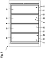
- Fig. 1 shows a schematic view of the folding door system 1 according to an embodiment of the invention.
- the folding wing door system 1 comprises a first folding wing door 2 and a second folding wing door 3.
- the first folding wing door 2 and the second folding wing door 3 each comprise a first wing 24 and a second wing 25 which are connected via a hinge system (cf. Figs. 2 to 4 ) are connected.
- the first wing 24 has a first frame 10
- the second wing 25 has a second frame 11.
- the individual wings 24, 25 are constructed identically, so that in particular the first frame 10 is also identical to the second frame 11.
- a filling element 22 is held both by the first frame 10 and by the second frame 11, the filling element 22 being in particular a glass pane.
- the wing door system 1 If the wing door system 1 is to be opened or closed, at least one of the folding wing doors 2, 3, ie either the first folding wing door 2 or the second folding wing door 3 or the first folding wing door 2 and the second folding wing door 3 together, is moved along a guide rail 8. Thus, the first wings 24 and second wings 25 are folded in relative to one another.
- the folding door system 1 therefore has a folding side into which the first wing 24 and the second wing 25 slide for folding.
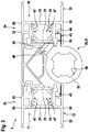
- the Fig. 2 shows a section through the first folding wing door 2 in a plan view.
- the first frame 10 and the second frame 11 each have two vertical profile elements 12 and two horizontal profile elements 13.
- the horizontal profile element 13 and the vertical profile element 12 are butted together and screwed.
- a counter element 49 is introduced into the horizontal profile element 13.
- the counter element 49 rests directly on the vertical profile element 12 and is screwed to the vertical profile element 12 via two fastening screws 66.
- the fastening screws 66 are supported on a fastening element 48 which is arranged in the vertical profile element 12.
- a defined contact pressure between the vertical profile element 12 and the horizontal profile element 13 can be set. This ensures a secure and, in particular, rigid connection. Due to the support of the fastening screws 66 on the fastening element, it is also ensured that the fastening screws 66 do not protrude from the vertical profile element 12 and thus make it more difficult to assemble the first wing 24 or the second wing 25.
- the vertical profile element 13 comprises two thermal separations 31 and two clamping elements 50, which are each arranged essentially perpendicular to one another.
- the clamping elements 50 serve to accommodate the filling element 22, while the thermal separations 31 thermally isolate the two clamping elements 50 from one another.
- a first outer surface 32 of the first frame 10 and of the second frame 11 is thermally separated from a second outer surface 33 of the first frame 10 and of the second frame 11, in particular opposite the first outer surface.
- the wing door system 1 thus also forms a thermal separation between those areas which are to be separated with the folding wing door system 1.
- a chamber 51 is formed within the vertical profile element 12.
- the fastening element 48 is attached within this chamber 51.
- the fastening element 48 is a perforated plate that is inserted into fastening grooves 47 (cf. Fig. 3 ) is inserted. This enables a very simple connection between the horizontal profile element 13 and the vertical profile element 12, the previously described avoidance of the fastening screws 66 protruding from the vertical profile element 12 being implemented at the same time.
- a first hinge element 20 is inserted into the first frame 10, while a second hinge element 21 is inserted into the second frame 11.
- the first frame 10, in particular the vertical profile element 12, has a groove 43 in the vertical direction.
- the first hinge element 20 is pushed into this groove 43.
- the second frame 11 also has a groove 43 into which the second hinge element 21 is inserted.
- first hinge element 20 and the second hinge element 21 have a fastening web 44.
- fastening web 44 With the fastening web 44, the first hinge element 20 is pushed into the groove 43 of the first frame 10 and the second hinge element 21 is pushed into the groove 43 of the second frame 11.
- Both the fastening web 44 and the groove 43 have an undercut 55, so that the first hinge element 20 is arranged in the groove 43 in a form-fitting manner in all directions except for the vertical. The same applies to the second hinge element 21.
- both the first hinge element 20 and the second hinge element 21 have a bar web 45.
- the strip web 45 is attached to the first hinge element 20 and to the second hinge element 21, in particular opposite the undercut 55.
- the bar web 45 there is a threaded bore 46 into which a grub screw can be screwed.
- the strip web 45 can be pushed away from the first frame 10 by screwing the grub screw into the threaded bore 46, whereby the groove 43 is pressed against the fastening web 44 at the same time.
- the first hinge element 20 can thus be pressed against the first frame 10, in particular against the vertical profile element 12, via the undercut 55.
- the pressure creates a frictional connection which, among other things, also acts in the vertical direction.
- the clamping of the first frame 10 between the fastening web 44 and the screwed-in grub screw into the threaded hole 46 of the strip web 45 enables the first hinge element 20 to be fully fixed.
- the first hinge element 20 and the second hinge element 21 have the advantage that they are only attached to an outer area of the first frame 10 and the second frame 11. This in particular prevents a cold bridge from being introduced into the vertical profile elements 13 along the thermal separations 31 as a result of the fastening of the hinge elements 20, 21. This guarantees a safe and reliable thermal separation. At the same time, a secure and rigid connection of the first hinge element 20 to the first frame 10 and of the second hinge element 21 to the second frame 11 is made possible. This leads to a very stable folding wing door 2, 3, which is why a lowering in the horizontal direction of the wings 24, 25 is very small even with large opening widths.
- first hinge element 20 In order to connect a first hinge element 20 to a second hinge element 21, the first hinge element 20 has a first sleeve-shaped area 52, while the second hinge element 21 has a second sleeve-shaped area 53.
- the connection of the first sleeve-shaped area 52 to the second sleeve-shaped area 53 is in particular shown in FIG Fig. 4 shown.
- a door bolt 54 is mounted on the inner surface 56 of the first sleeve-shaped area 52 and the second sleeve-shaped area 53, in particular via a bearing in each case.
- the inner surface 56 of the sleeve-shaped areas 52, 53 have the shape of a hollow spline shaft, as a result of which the bearing of the door bolt 54 is mounted in the first sleeve-shaped area 52 and the second sleeve-shaped area 53 in a rotationally fixed manner.
- the bearing of the door bolt 54 is mounted in the first sleeve-shaped area 52 and the second sleeve-shaped area 53 in a rotationally fixed manner.
- each first sleeve-shaped area 52 can be connected to two second sleeve-shaped areas 53, with every second sleeve-shaped area 53 also being connectable to two first sleeve-shaped areas 52.
- the folding wing door 2, 3 can be assembled very flexibly from the first wing 24 and the second wing 25. Due to the number of first hinge elements 20 and second hinge elements 21, the rigidity of the mounting of the first wing 24 and the second wing 25 on one another can be adjusted.
- the Fig. 5 shows a drive for the folding wing door system 1.
- a drive unit 4 which is in particular a direct current electric motor.
- the drive unit 4 is connected to a transmission 5 which drives a converting device 6.
- the converting device 6 is in particular a disk or comprises two lever arms, a linkage 7 being attached to the outer regions of the disk or the lever arms.
- each folding door 2, 3 has its own linkage 7.
- the rotation of the transmission 5 is converted into a translation of the linkage 7 by the conversion device 6.
- the drive unit 4 is activated accordingly, whereby it applies a torque to the gear mechanism 5.
- the torque is applied to the converting device 6 via the transmission 5, in which the torque is converted into a tensile force within the linkage 7.
- a control unit 19 is provided to control the drive unit 4.
- the folding wing door system 1 also has a monitoring device 23 with which a movement of the folding wing doors 2, 3 can be monitored. This is discussed below with reference to the Figs. 10-15 described.
- each folding door 2, 3 has a carriage 9.
- An exploded view of the carriage 9 is shown in FIG Fig. 6 shown.
- the carriage 9 comprises a base body 26 which has a plurality of bores.
- Four vertical rollers 15 can be introduced into four of these bores, the vertical rollers 15 having an axis 65 which is non-positively fastened within the bores of the base body 26.
- a roller body 16 is mounted on the axle 65 via a bearing 30, in particular via a closed ball bearing.
- the roller body 16 has a roller surface 17 which runs on a running surface 18 of the guide rail 8.
- the vertical rollers 15 in particular have a diameter of 100 mm.
- the base body 26 also has a through opening 29 through which a bolt 27 is guided.
- a horizontal roller 14 is mounted on the bolt 27.
- the horizontal roller 14 is in particular mounted directly on the bolt 27, that is to say without an additional bearing.
- the horizontal running roller 14 has a larger diameter than the vertical running rollers 15.
- the horizontal running roller 14 has a convex running surface. The horizontal roller 14 is used to guide the carriage 9 laterally within the guide rail 8.
- a suspension 28 for the folding wing door 2, 3 is attached to the bolt 27.
- the suspension 28 is screwed onto a thread of the bolt 27.
- the folding door system 1 can therefore be adapted to a large number of environmental conditions.
- a sealing element 34 is provided for this purpose.
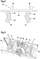
- the sealing element 34 is shown schematically in FIG Fig. 8 shown.
- the sealing effect of the sealing element 34 is shown in Fig. 9 shown.
- the sealing element 34 comprises a plate-shaped base area 35 as well as a first tubular sealing area 36 and a second tubular sealing area 41.
- a wall thickness of the tubular sealing area 41 is between 0.5 mm and 1.5 mm, in particular 1.0 mm.
- a wall thickness of the base region 35 is between 0.5 mm and 2.0 mm, in particular between 1.0 mm and 1.5 mm.
- Both the first sealing area 36 and the second sealing area 41 are arranged on the same side of the base area 35 and are in particular aligned symmetrically to one another.
- two undercut elements 42 are arranged, with which the sealing element 34 can be attached to the vertical profile elements 13 of the first frame 10 and the second frame 11. It is also provided that both the first frame 10 and the second frame 11 are covered by the base region 35 of the sealing element 34.
- the sealing element 34 thus fulfills a first sealing effect by sealing the vertical profile elements 13.
- a second sealing effect occurs when the first sealing area 36 and the second sealing area 41 of a sealing element 34 rest on the base area 35 of another sealing element 34.
- the first sealing area 36 and the second sealing area 41 of a sealing element 34 which is attached to a movable end 38 of the first folding wing door 2 is arranged, in a closed state of the folding wing door system 1 rests on the base region 35 of the sealing element 34 that is attached to the movable end 38 of the second folding wing door 3. It is provided here that the first sealing area 36 and the second sealing area 41 are deformed when they come into contact with the base area 35 of another sealing element 34, so that a pressing force is applied by the sealing element 34 itself. This ensures a high level of tightness.
- the first sealing area 36 and the second sealing area 41 each have a first leg 39 and a second leg 41.
- the first leg 39 is attached to the base region 35, while the second leg 40 is attached to the first leg 39.
- the first leg 39 is angled with respect to the base region 35. The bend is designed such that the first leg 39 of the first sealing area 36 points in the direction of the second sealing area 41.
- the first leg 39 of the second sealing area 41 points in the direction of the first sealing area 36.
- the second leg 40 of the first sealing area 36 points away from the second sealing area 41
- the second leg 40 of the second sealing area 41 also points away from the first Sealing area 36 away.
- a first angle between the first leg 39 and the second leg 40 is preferably between 120 ° and 150 °, particularly preferably 135 °.
- a second angle between the first leg 39 and the base region 35 is between 55 ° and 80 °, in particular 68 °.
- the folding door system 1 is located in the in Fig. 9 shown state in a closed position, so that the sealing elements 34 attached to the movable ends 38 of the first folding wing door 2 and the second folding wing door 3 rest against one another.
- Fig. 9 no deformation of the sealing elements 34 is shown, but it is shown schematically how far the first sealing areas 36 and the second sealing areas 41 would penetrate into the respective opposing base areas 35 if these were not deformed. So it's over Fig. 9 It can be seen that a considerable deformation of the sealing elements 34 is necessary to close the folding wing doors 2, 3, so that the first sealing areas 36 and the second sealing areas 41 generate a high restoring force. This ensures that the sealing elements 34 are pressed firmly onto one another.
- the sealing element 34 is used to adapt to the kinematics of the folding door system 1.
- the conventional seal has to be strongly compressed, which results in an increased driving force of the drive unit 4.
- the first sealing areas 36 and the second sealing areas 41 can be easily deformed, as a result of which low drive forces act within the drive unit 4.
- the drive unit 4 is spared, on the other hand there is no risk of an incorrectly occurring error message due to excessive drive forces.
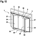
- a folding door system 1 is shown schematically, the folding doors 2 being in different positions. So is in Fig. 10 the folding door system 1 fully open, in Fig. 11 completely closed and in Fig. 12 partially open.
- the folding door system 1 has an obstacle sensor 57 which generates a sensor field 59.
- the obstacle sensor 57 can thus detect whether an obstacle, in particular a person, is located within the sensor field 59.
- the obstacle sensor 57 is in particular an optical sensor.
- a projection 58 of the sensor field 59 results as an ellipse on a floor on which the folding door system 1 is mounted.
- a passage from a first area 60 to a second area 61 can be opened or closed.
- movable ends 38 of the first folding wing door 2 and the second folding wing door 3 are moved along the guide rail 8 in the direction of the fixed ends 37 of the first folding wing door 2 and the second folding wing door 3.
- the first folding wing door 2 and the second folding wing door 3 are fastened to a wall and / or to a floor at the fixed ends 37, rotation being made possible.
- the folding doors 2, 3 are folded in the direction of the first area 60. This means that the first wings 24 and the second wings 25 of the folding doors 2, 3 are always located within the first area 60, but never within the second area 61.
- FIG. 12 One problem with this movement is in Fig. 12 shown. It can be seen here that the folding wing doors 2, 3 bear directly on the sensor field 59, in particular on the projection 58 of the sensor field 59 of the obstacle sensor 57.
- the projection 58 thus has a first entry region 63, into which the first folding wing door 2 enters during an opening process or a closing process, while the second folding wing door 3 enters a second entry region 64 of the projection 58.
- the monitoring device 23 is set up, which is shown in FIG Fig. 16 or 17th the flowcharts shown. In the Fig. 16 and 17th flow charts shown are described below with reference to the Figs. 13-15 explained.
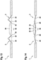
- Figs. 13-15 show a plan view of a schematic folding wing door system 1 according to the embodiment of the invention.
- the folding door system 1 is partially closed, the first folding door 2 and the second folding door 3 remaining outside the sensor field 59, in particular outside the projection 58 of the sensor field 59.
- Fig. 5 It can be seen that the first folding wing door 2 and the second folding wing door 3 remain in a completely closed position outside the projection 58.
- Fig. 14 shows a state in which the first folding wing door 2 lies directly against the first entry region 63 and the second folding wing door 3 lies directly against the second entry region 64. If the first folding wing door 2 and the second folding wing door 3 execute a closing movement, they have just left the sensor field 59. In this state, the first folding wing door 2 and the second folding wing door 3 are located within an activation area 62.
- the activation area 62 corresponds to a predefined width of the guide rail 8 along the direction of travel of the folding wing doors 2, 3, this width being symmetrical around a center point between the first folding wing door 2 and second folding door 3 is arranged.
- the position of the first folding wing door 2 and the second folding wing door 3 is thus defined in particular by the position of the movable ends 38 on the guide rail 8. If the movable ends 38 and thus the first folding wing door 2 and the second folding wing door 3 are located within the activation area 62, the first folding wing door 2 is located outside the first entry area 63 and the second folding wing door 3 is located outside the second entry area 64.
- the obstacle sensor 57 is active at all times.
- the sequence begins with an initial step S00. Then, in a first step, it is determined whether the first folding door 2 and the second folding door 3 execute a closing movement. This can be determined in particular using a position sensor (not shown).
- the position sensor is in particular an incremental encoder which is arranged on the axis of rotation of the drive unit 4.
- the position sensor can be used to determine the position in which the first folding wing door 2 and the second folding wing door 3 are, and on the other hand it can also be determined whether the first folding wing door 2 and the second folding wing door 3 are currently executing a closing movement.
- the second step S02 is carried out. It is queried here whether an object within the sensor field 59, in particular the projection 58, was detected with the obstacle sensor 57. If this is the case, the process continues with the third step S03. However, if this is not the case, the sequence proceeds to a final termination step S05.
- the third step S03 it is queried whether the first folding door 2 and the second folding door 3 are located within the activation area 62. If this is the case, the closing movement of the first folding wing door 2 and the second folding wing door 3 is stopped or reversed in a fourth step S04. Since the first folding wing door 2 and the second folding wing door 3 are located within the activation area 62, a detection of the first wing 24 or the second wing 25 of the first folding wing door 2 or the second folding wing door 3 within the projection 58 and thus a false detection of nonexistent Obstacle excluded. A detected obstacle must therefore be an external obstacle, for example someone walking through the folding door system 1. It is therefore necessary to stop and / or reverse. The final termination step S05 is then carried out.
- the obstacle sensor 57 is permanently activated, signals from the obstacle sensor not being used at all times.
- the signals from the obstacle sensor are only observed when the first folding wing door 2 and the second folding wing door 3 are located within the activation area 62.
- Fig. 17 an energy-saving variant of the process is shown.
- an initial step S10 begins the sequence.
- a first step S11 it is determined whether the first folding wing door 2 and the second folding wing door 3 execute a closing movement. If this is the case, it is determined in a second step S12 whether the first folding door 2 and the second folding door 3 are located within the activation area 62. If this is not the case, the obstacle sensor 57 is deactivated in a third step S13 and the process continues with the first step S11.
- the folding door system 1 is in a position in which the signal from the obstacle sensor 57 is not reliable, since in this position an incorrect detection of the first folding door 2 or the second folding door 3 as an obstacle is possible. Since the obstacle sensor 57 does not provide any reliable data, it makes sense to deactivate the obstacle sensor 57 in order to be able to save energy.
- the obstacle sensor 57 is activated in a fourth step S14.
- a fifth step S15 it is then checked whether the obstacle sensor 57 has detected an obstacle. If this is not the case, a sixth step S16 continues again with the second step S12. If, on the other hand, an obstacle is detected, the closing movement of the first folding wing door 2 and the second folding wing door 3 is stopped and / or reversed in a seventh step S17. Again, in this case it can be assumed that the detected obstacle is an external obstacle, for example someone walking through the folding door system 1, which is why stopping and / or reversing is necessary. The sequence is then ended with a final termination step S18.
- the obstacle monitoring makes it possible to realize a closing movement of the folding door system 1 not exclusively by monitoring the power consumption of the drive unit 4. In this case, an obstacle would have to come into contact with the closing folding door system 1 so that the obstacle can be detected. However, people in particular find contact with the closing folding door system 1 very uncomfortable, which is why this should be avoided if possible.
- the sensor field 59 in particular also the projection 58, has to be arranged outside a passage plane of the folding wing door system 1, the problem must always be expected that the obstacle sensor 57 incorrectly interprets the first wing 24 or the second wing 25 of the folding wing doors 2, 3 Recognizes obstacle.
- obstacle monitoring by means of obstacle sensor 57 would only be possible with a very precise setting of projection 58 of sensor field 59.
- the sensor field 59 would have to be aligned in such a way that retraction of the folding wing doors 2, 3 is safely and reliably avoided. This complex setting of the obstacle sensor is avoided by the aforementioned processes.
- the Fig. 18 shows a flow chart of a wind load control, which is carried out in particular by the control unit 19 of the folding door system 1.
- a wind load regulation has the meaning that the folding wing doors 2, 3 remain in the closed position even in the presence of strong gusts of wind and are not pushed open by the wind.
- the in Figure 18 The flow chart shown is run through in the control unit every ten milliseconds.
- the folding door system 1 is in the closed position. If it is now recognized on the basis of the position sensor that the folding doors 2, 3 are not in the closed position, this must have been caused by a gust of wind. Alternatively, this can also be done be done by a force applied by hand to the folding door system 1. In both cases, however, it is undesirable for the folding doors 2, 3 to open.
- the wind load control is thus implemented in such a way that it tries to minimize a deviation of the door position of the folding wing doors 2, 3 from the target position, that is to say from the closed position.
- the position sensor is used to determine the door position.
- the position sensor is in particular an incremental encoder which is arranged on a motor shaft of the drive unit 4.
- the incremental encoder has a resolution between 3,000 and 35,000, preferably between 5,000 and 30,000, particularly preferably between 7,500 and 2,000, pulses per travel distance between the open position and the closed position of the folding door system 1. With such a resolution it is ensured that the positions of the first folding wing door 2 and the second folding wing door 3 can be reliably detected.
- the wind load control as shown in Figure 18 essentially comprises three rule complexes which are initialized by a first step S21, by a fourth step S24 and by a sixth step S26. These sets of rules have different tasks, which are described in detail below: After an initialization step S20, it is queried in the first step S21 whether the folding door system 1 has opened by more than a predefined limit value within a predefined time period.
- the predefined time period is in particular the processing time, thus preferably ten milliseconds.
- the predefined limit value is advantageously 20, particularly advantageously 43, pulses from the incremental encoder. If such an opening is recognized, the process continues with the second step S22.
- a power which is output to the drive unit 4 and which causes a closing force on the folding wing doors 2, 3 is increased.
- the power is electrical power, the electrical voltage preferably being constant.
- the power is regulated via the current strength. It is therefore particularly preferably provided that the current delivered to the drive unit 4 is increased in the second step S22.
- the increase is advantageously 500 mA.
- the drive unit 4 With the increased current, the drive unit 4 generates an increased closing force which acts on the first folding wing door 2 and on the second folding wing door 3. On the one hand, this closing force causes a locking force when the folding door system 1 is in the fully closed position; on the other hand, the closing force closes the wings 24, 25 of the folding door system 1 that have been opened by gusts of wind.
- a timer is finally started which in particular is 15 minutes.
- the first set of rules ensures that the folding door system 1 is not opened again with repeated gusts.
- it is determined whether there is a strong gust of wind, since only a strong gust of wind enables the large opening within the short time. If a strong gust of wind is detected, it can be assumed that this strong gust of wind is followed by further gusts of wind, which mostly have at most the same strength as the gust of wind initially detected.
- the folding wing door system 1 can remain in a closed position, even if subsequent gusts of wind act on the folding wing doors 2, 3.
- Starting the counter in the third step S23 enables the current increased in the second step S22 to be gradually reduced. This reduction is the subject of the second set of rules, which is initiated with the fourth step S24.
- the fourth step S24 asks whether the time counter has been started. If this is the case, the fifth step S25 is carried out at regular intervals. In particular, the regular intervals are every three minutes. In the fifth step S25, the current increased in the second step S22 is finally reduced, in particular by 100 mA each time. The process then continues with the sixth step S26. This is preferably repeated five times so that after 15 minutes that the timer is running, the increased current is reduced five times by 100 mA. After the 15 minutes have elapsed, the current increased in the second step S22 is thus completely reduced again. In this way, in particular, overloading the drive unit 4 is avoided.
- the third set of rules is initiated with the sixth step S26.
- the sixth step S26 it is determined whether the folding doors 2, 3 deviate from the completely closed position. As already described above, such a deviation is generated in particular by a wind load or by a manual force on the leaves 24, 25 of the folding leaf door system 1. Since the folding door system 1 should remain in the completely closed position, such a deviation is undesirable.
- the process continues with the seventh step S27.
- the current that is output to the drive unit 4 is increased.
- the increase takes place in particular linearly to the deflection of the folding doors 2, 3 from the completely closed position.
- a p-controller is thus implemented.
- step S27 As a result of the regulation in the seventh step S27, it can happen that a power output to the drive unit 4 exceeds a nominal power of the drive unit 4. In particular, the output current then exceeds a predetermined maximum nominal current. This is checked in an eighth step S28. If the maximum rated current is exceeded, the process continues with the ninth step S29. If, on the other hand, there is no exceedance, the sequence is ended with the termination step S30.
- the current applied to the drive unit in the seventh step S27 is reduced to the maximum rated current. This takes place in particular within a predetermined time period, which is advantageously ten seconds.
- the brief overloading of the drive unit ensures that the folding door system 1 remains in the closed position even in the event of strong gusts of wind.
- a drive unit 4 with a high maximum nominal power is not to be used; instead, due to the monitoring of the power delivered to the drive unit 4 in the eighth step S28, a drive unit 4 with a low maximum nominal power can also be used be used. Since a spatial dimension of the drive unit 4 usually increases with increasing nominal power, it is thus possible to use a small and compact drive unit 4. In this way, a filigree folding door system 1 can be implemented, which nevertheless has a sufficiently high-performance wind load control, so that the folding door system 1 remains in the closed position even when strong gusts of wind occur.
- FIG. 4 shows travel curves of the folding door system 1 during opening and closing of the folding doors 2, 3.
- the upper diagram shows a speed profile
- the lower diagram shows a profile of the acceleration.
- a position of the folding wing doors 2, 3 is shown on the abscissa axis, that is to say a position of the movable end 38 on the running rail 8. This means that the folding door system 1 is completely closed at a left limit value, while the folding door system 1 is completely open at a right limit value on the abscissa axis.
- the coordinate axes of the diagrams indicate a speed in the upper diagram and an acceleration of the folding wing doors 2, 3 in the lower diagram.
- the folding doors 2, 3 behave according to the upper curve of the diagrams. If, however, the folding door system 1 is closed, the folding doors 2, 3 behave according to the lower curves of the diagrams.
- the profiles of the speed and acceleration shown allow the folding door to be opened quickly, while at the same time vibrations within the folding door system 1 are avoided both when opening and when closing. Due to the reduction in the vibrations, a lowering of the leaves 24, 25 of the folding leaf door system 1 is minimized, which is why they can have a small distance from a floor. Thermal insulation is thus increased. At the same time, the reduction of vibrations and the resulting minimal lowering of the folding doors 2, 3 allow a large opening width to be achieved. In particular, a maximum opening width of 2,400 millimeters is made possible in this way. This means that when using four blades 24, 25, as shown in FIG Figure 1 has been shown, each wing has a width of 60 millimeters.
- the wings 24, 25 are finally decelerated.
- a negative acceleration is applied to the folding wing doors 2, 3, the maximum negative acceleration being in particular 50 percent higher than is the maximum positive acceleration of the folding doors 2, 3.
- the rapid deceleration of the wings 24, 25 thus effected allows the end stop to be reached gently in the open position.
- the folding door system 1 can be opened very quickly, so that a user who wants to pass through the folding door system 1 does not have to wait for the folding door 2, 3 to open.
- a maximum closing speed of the folding wing doors 2, 3 is a maximum of half the maximum opening speed of the folding wing doors 2, 3. This enables monitoring of the closing process in particular, since the reduced speed when closing the folding wing door system 1 monitors the closing movement allowed.
- the folding door system 1 can therefore stop and / or reverse the leaves 24, 25 when an obstacle is detected within the travel path of the folding door 2, 3, which enables very safe operation of the folding door system 1.
- a vertical profile element 12 of the first frame 10 or the second frame 11 in the center of gravity a first main moment of inertia between 30,000 mm 4 and 60,000 mm 4 , preferably 48,470 mm 4 .
- a second main moment of inertia is between 60,000 mm 4 and 80,000 mm 4 , preferred 73,570 mm 4 .
- a polar moment of inertia is between 120,000 mm 4 and 130,000 mm 4 , preferably 122,041 mm 4 .
- the vertical profile element 12 of the first frame 10 or of the second frame 11 has a first main moment of inertia between 20,000 mm 4 and 40,000 mm 4 , preferably of 31,934 mm 4, in the center of gravity.
- a second main moment of inertia is between 50,000 mm 4 and 80,000 mm 4 , preferably 65,389 mm 4 .
- a polar moment of inertia is between 85,000 mm 4 and 110,000 mm 4 , preferably 97,324 mm 4 .
- a horizontal profile element 13 of the first frame 10 or of the second frame 11 has a first main moment of inertia between 85,000 mm 4 and 120,000 mm 4 , preferably of 102,266 mm 4 , in the center of gravity.
- a second main moment of inertia is between 85,000 mm 4 and 120,000 mm 4 , preferably 103,497 mm 4 .
- a polar moment of inertia is between 150,000 mm 4 and 250,000 mm 4 , preferably 205,763 mm 4 .
- the guide rail is made of a material with a modulus of elasticity at 20 ° C. between 60 MPa and 80 MPa, preferably 70 MPa.
- the modulus of elasticity is determined in accordance with EN ISO 6892-1: 2009.
- a shear modulus of the material of the guide rail 8 which can be determined in accordance with DIN 53445 in particular, is between 10 MPa and 40 MPa, preferably 27 MPa, at 20 ° C.
- a very rigid frame 10, 11 is provided around the filling element 22, so that a lowering of the first wing 24 or the second wing 25 and thus in the first folding wing door 2 or the second folding wing door 3 is minimized.
- a maximum opening width of 2,400 millimeters can be achieved in this way, with a maximum lowering of the folding wing doors 2, 3 over the entire travel path between the closed position and the open position being a maximum of four millimeters.
- This allows a sufficiently high gap sealing between a lower edge of the folding wing doors 2, 3 and a floor receiving the folding wing door system 1.
- the folding door system 1 can still be operated very quietly. This is achieved in that the transmission and emission of structure-borne noise in the individual components of the folding door system 2 is minimized.
- the roller body 16 of the rollers 14, 15 has a modulus of elasticity at 20 ° C. between 2,700 MPa and 3,100 MPa, preferably 2,900 MPa.
- the roller body 16 has a density between 1.10 g / cm 3 and 1.70 g / cm 3 , preferably 1.42 g / cm 3, at 20 ° C.
- the modulus of elasticity is determined in accordance with ISO 527.
- the density is determined in accordance with ISO 1183.
- the running surface 18 of the guide rail 8 has a modulus of elasticity at 20 ° C. between 60 MPa and 80 MPa, preferably of 70 MPa. Furthermore, the running surface 18 has a shear modulus between 10 MPa and 40 MPa, preferably 27 MPa, at 20 ° C. A density in the running surface 18 is finally between 3 g / cm 3 and 5 g / cm 3 , preferably 2 g / cm 3 , at 20 ° C.
- the modulus of elasticity is determined in accordance with EN ISO 6892-1: 2009. The shear modulus is determined according to DIN 53445, the density in turn according to ISO 1183.
- the base body 26 of the carriage 9 has a modulus of elasticity at 20 ° C. between 2,500 MPa and 2,900 MPa, preferably 2,700 MPa.
- a shear modulus of the base body 26 is between 600 MPa and 900 MPa, preferably 750 MPa, at 20 ° C.
- the density of the base body 26 is finally between 1.10 g / cm 3 and 1.70 g / cm 3 , preferably 1.39 g / cm 3 , at 20 ° C.
- the modulus of elasticity is again determined in accordance with ISO 527, the shear modulus in accordance with DIN ISO 1827: 2010-07.
- the density is again determined according to ISO 1183.
- the roller surfaces 17 of the rollers 14, 15 have a surface roughness Rz between 5.0 ⁇ m and 7.0 ⁇ m, preferably 3.0 ⁇ m.
- the entire roller body 16 has such a surface roughness.
- the surface hardness of the roller body 16 is M 92 according to the Rockwell scale.
- the running surface 18 preferably has a groove, the groove being oriented parallel to a direction of displacement of the carriage 19. Grooving is to be understood as a regular, wave-like pattern on the surface of the running surface 18.
- the grooves have a surface roughness Ra, measured in the longitudinal direction, of 0.05 to 1.0, preferably 0.5. In this way, low noise emissions are also achieved on the part of the running surface 18 due to low energy losses.
- a static surface pressure between a roller surface 17 of the running rollers 14, 15 and the running surface 18 is between 8 N / mm 2 and 12 N / mm 2 , preferably 10 N / mm 2 .
- the travel speed of the carriage 9 with respect to the guide rail 8 is between 10 cm / s and 100 cm / s, preferably between 10 cm / s and 75 cm / s, particularly preferably between 10 cm / s and 50 cm / s. Since the friction is fundamentally dependent on the speed, these values can be used to minimize friction and thus energy loss and thus also noise emissions. This in turn ensures that the folding door system 1 is operating very quietly.
- a length of the base body 26 is between 40 mm and 80 mm, preferably 60 mm.
- a width of the base body 26 is between 15 mm and 20 mm, preferably 18 mm.
- a height of the base body 26 is between 10 mm and 15 mm, preferably 13 mm.
- the vertical rollers 15 attached to the base body 26 have a radius between 75 mm and 125 mm, preferably 100 mm.
- the connection between the vertical roller 15 and the base body 26 takes place via an axis 65.
- the axis 65 has a modulus of elasticity at 20 ° C. between 150 MPa and 250 MPa, preferably of 200 MPa.
- a shear modulus at 20 ° C. of the axis 65 is between 70 MPa and 90 MPa, preferably 81 MPa.
- a density of the axis 65 at 20 ° C. is between 5.0 g / cm 3 and 10.0 g / cm 3 , preferably 7.9 g / cm 3 .
- the modulus of elasticity is determined in accordance with EN ISO 689-1: 2009, the shear modulus in accordance with DIN 53445 and the density in accordance with ISO 1183.
- a flattening of the rollers 14, 15 leads to the generation of interfering noises due to long idle times.
- a flattening of the rollers 14, 15, in particular the vertical rollers 15, after eight hours of resting on a flat surface and loading with a test load of 200 N is a maximum of 0.20 mm, preferably a maximum of 0.12 mm. This slight flattening ensures that the rollers 14, 15 do not run out of round if the folding door 1 has a long service life.
- a water absorption of the roller body 16 after immersion in water of 23 degrees is between 0.1 and 0.5, preferably 0.3.
- a water absorption of the roller body 16 after storage at 50 percent relative humidity is between 1.2 and 1.6, preferably 1.4.
- the water absorption is determined according to ISO 62. In particular, method 1 (immersion in water at 23 degrees) and method 4 (storage at 50 percent relative humidity) are used. These values ensure that an increase in the volume of the rollers 14, 15 when absorbing water does not lead to out-of-round running and thus to interfering noises.
- the folding doors 2, 3 have a maximum heat transfer coefficient U D of 3.0 W / (m 2 K).
- the maximum heat transfer coefficient U D is a maximum of 1.7 W / (m 2 K).
- the frame 10, 11 of the folding wing doors 2, 3 is made in particular from a material that has a heat transfer coefficient U D between 2.0 W / (m 2 K) and 4.0 W / (m 2 K).
- the filler element 22 of the folding wing doors 2, 3 comprises a material with a heat transfer coefficient U D between 0.5 W / (m 2 K) and 1.5 W / (m 2 K), preferably 1.0 W / (m 2 K) ). With these values, the aforementioned low heat transfer through the folding door system 1 is made possible.
- both the first frame 10 and the second frame 11 in the vertical profile elements 12, 12 have thermal separations 31.
- the thermal separations 31 are in particular insulation webs, the thermal separations 31 made of a material with a coefficient of thermal conductivity between 0.1 W / (m 2 K) and 0.3 W / (m 2 K), preferably 0.2 W / ( m 2 K).
- a modulus of elasticity of the thermal separation 31 is between 400 MPa and 3,000 MPa at 20 ° C., the modulus of elasticity being measured in accordance with DIN 53457 in particular.
- the thermal separation 31 is a material with a coefficient of linear expansion between 0.10 mm / (m K) and 0.25 mm / (m K), preferably between 0.15 mm / (m K) and 0.20 mm / (m K). Sufficient thermal insulation is thus ensured by the thermal separation 31, as a result of which the heat transport through the first frame 10 and the second frame 11 is minimized.
- the filling element 22 comprises a material with a coefficient of thermal conductivity between 0.60 W / (m 2 K) and 0.90 W / (m 2 K), preferably of 0.76 W / (m 2 K).
- a modulus of elasticity of the filling element 22 at 20 ° C. is between 50 GPa and 90 GPa, preferably 70 GPa.
- the filling element 22 comprises a material with a coefficient of linear expansion of 0.01 mm / (m K). The heat transport through the filling element 22 is thus also minimized.
- the filling element 22 is connected to the first frame 10 and the second frame 11 via an adhesive.
- the adhesive has a tensile strength between 1.0 N / mm 2 and 2.5 N / mm 2 , preferably 1.8 N / mm 2 .
- the tensile strength can be determined according to ISO 527 in particular.
- the folding door system 1 has seals in the form of brushes. These brushes seal the gap between the folding door 2, 3 and the floor or guide rail 8.
- the seals in the form of brushes have a trim that has a bristle length between 12 mm and 20 mm, preferably 15.9 mm.
- a base body of the brushes comprises a round base body which in particular has a diameter between 2.0 mm and 4.0 mm, preferably 2.9 mm. In this way, a secure and adequate sealing of a gap between the folding wing door 2, 3 and the floor or guide rail 8 is made possible. A heat transport through this gap is therefore almost prevented.
- a thermal bridge addition between the filling element 22 and the first frame 10 or the second frame 11 is between 0.050 W / (m 2 K) and 0.060 W / (m 2 K), preferably 0.056 W / (m 2 K).
- a thermal bridge allowance between the first frame 10 and the second frame 11 and a wall accommodating the frames is between 0.050 W / (m 2 K) and 0.060 W / (m 2 K), preferably 0.056 W / (m 2 K).
Landscapes
- Engineering & Computer Science (AREA)
- Mechanical Engineering (AREA)
- Civil Engineering (AREA)
- Structural Engineering (AREA)
- Extensible Doors And Revolving Doors (AREA)
Claims (7)
- Installation de porte à vantaux pliants (1), comportant- au moins une porte à vantaux pliants (2, 3) avec au moins deux vantaux (24, 25) et au moins un corps à charnière (20, 21) agencé entre eux,- chaque vantail (24) comprenant un cadre (10, 11),- chaque cadre (10, 11) comprenant une rainure (43), dans laquelle une barrette d'attachement (44) du corps à charnière (20, 21) est insérable,- la rainure (43) et la barrette d'attachement (44) comprenant une contre-dépouille (55) de façon à avoir une connexion positive entre cadre (10 ,11) et corps à charnière (20, 21),- le corps à charnière (20, 21) comprenant une barrette à listel (45),- la barrette à listel (45) étant connectable au cadre (10, 11),- la barrette à listel (45) ayant au moins un trou taraudé (46), dans lequel un boulon d'attachement est vissable et pouvant être pressé contre le cadre (10, 11),- la porte à vantaux pliants (2, 3) comportant au moins un premier vantail (24) avec un premier cadre (10) et au moins un deuxième vantail (25) avec un deuxième cadre (11), un premier corps à charnière (20) étant agencé au premier cadre (10) et un deuxième corps à charnière (21) étant agencé au deuxième cadre (11), le premier corps à charnière (20) étant supportable au moins à deux deuxièmes corps à charnière (21) et le deuxième corps à charnière (21) étant supportable au moins à deux premiers corps à charnière (20), et- le premier corps à charnière (20) ayant une première région en forme de gaine (52) et le deuxième corps à charnière (21) une deuxième région en forme de gaine (53), la première région en forme de gaine (52) et la deuxième région en forme de gaine (53) étant supportées l'une à l'autre, tout particulièrement verticalement l'une au-dessus de l'autre, via un boulon de porte (54) supporté.
- Installation de porte à vantaux pliants (1) selon la revendication 1, caractérisée en ce que la barrette à listel (46) est agencée à l'opposé de la contre-dépouille (55).
- Installation de porte à vantaux pliants (1) selon la revendication 1 ou 2, caractérisée en ce que le premier corps à charnière (20) est supporté de façon rotative au deuxième corps à charnière (21) et/ou à un plancher entourant l'installation de porte à vantaux pliants (1) et/ou à un plafond entourant l'installation de porte à vantaux pliants (1).
- Installation de porte à vantaux pliants (1) selon l'une des revendications précédentes, caractérisée en ce qu'une somme des longueurs, tout particulièrement la dimension en direction verticale, du premier corps à charnière (20) et du deuxième corps à charnière (21) correspond au maximum à la hauteur totale et au minimum comprise entre 85 % et 95 %, tout particulièrement entre 88 % et 92 %, de la hauteur, tout particulièrement de la dimension in direction verticale, du premier vantail de porte ou du deuxième vantail de porte.
- Installation de porte à vantaux pliants (1) selon l'une des revendications précédentes, caractérisée en ce que la rainure (43) est agencée dans un élément de profil vertical (12) du cadre (10, 11) et/ou est orientée verticalement.
- Installation de porte à vantaux pliants (1) selon l'une des revendications précédentes, caractérisée en ce que la rainure (43) est agencée dans une région de bord extérieure d'un élément de profil (12, 13) du cadre (10, 11), la région de bord extérieure s'étendant d'une surface extérieure (32, 33) à concurrence au maximum d'un tiers, tout particulièrement à concurrence au maximum d'un quart, de l'épaisseur de l'élément de profil (12, 13) dans l'élément de profil (12, 13).
- Méthode pour produire une installation de porte à vantaux pliants (1), tout particulièrement selon la revendication 1, caractérisée par les étapes :- mettre à disposition d'un cadre (10, 11), le cadre (10, 11) ayant une rainure (43),- insérer un élément de remplissage (22) dans le cadre (10, 11),- réaliser un vantail (24, 25) en montant au moins un corps à charnière (20, 21) au cadre (10, 11),- combiner au moins deux vantaux (24, 25) pour en faire une porte à vantaux pliants (2, 3),- une barrette d'attachement (44) du corps à charnière (20, 21) étant insérée dans la rainure (43), et- la rainure (43) et la barrette d'attachement (44) ayant une contre-dépouille (55) de façon à avoir une connexion positive entre cadre (10 ,11) et corps à charnière (20, 21),- le corps à charnière (20, 21) comprenant une barrette à listel (45), et- la barrette à listel (45) étant connectable au cadre (10, 11),- comportant l'étape de serrer la contre-dépouille (55) de la rainure (43) entre barrette d'attachement (43) et un boulon d'attachement, lequel est vissable dans un trou taraudé (46) de la barrette à listel (45) et peut être pressé contre le cadre,- la porte à vantaux pliants (2, 3) comportant au moins un premier vantail (24) avec un premier cadre (10) et au moins un deuxième vantail (25) avec un deuxième cadre (11), un premier corps à charnière (20) étant agencé au premier cadre (10) et un deuxième corps à charnière (21) étant agencé au deuxième cadre (11), le premier corps à charnière (20) étant supportable au moins à deux deuxièmes corps à charnière (21) et le deuxième corps à charnière (21) étant supportable au moins à deux premiers corps à charnière (20), et- le premier corps à charnière (20) ayant une première région en forme de gaine (52) et le deuxième corps à charnière (21) une deuxième région en forme de gaine (53), la première région en forme de gaine (52) et la deuxième région en forme de gaine (53) étant supportées l'une à l'autre, tout particulièrement verticalement l'une au-dessus de l'autre, via un boulon de porte (54) supporté.
Priority Applications (1)
| Application Number | Priority Date | Filing Date | Title |
|---|---|---|---|
| EP14198616.6A EP3034732B1 (fr) | 2014-12-17 | 2014-12-17 | Installation de porte battante pliante |
Applications Claiming Priority (1)
| Application Number | Priority Date | Filing Date | Title |
|---|---|---|---|
| EP14198616.6A EP3034732B1 (fr) | 2014-12-17 | 2014-12-17 | Installation de porte battante pliante |
Publications (2)
| Publication Number | Publication Date |
|---|---|
| EP3034732A1 EP3034732A1 (fr) | 2016-06-22 |
| EP3034732B1 true EP3034732B1 (fr) | 2021-02-17 |
Family
ID=52102598
Family Applications (1)
| Application Number | Title | Priority Date | Filing Date |
|---|---|---|---|
| EP14198616.6A Active EP3034732B1 (fr) | 2014-12-17 | 2014-12-17 | Installation de porte battante pliante |
Country Status (1)
| Country | Link |
|---|---|
| EP (1) | EP3034732B1 (fr) |
Citations (2)
| Publication number | Priority date | Publication date | Assignee | Title |
|---|---|---|---|---|
| DE1945028A1 (de) * | 1969-09-05 | 1971-03-11 | Ver Baubeschlag Gretsch Co | Anordnung von Beschlagteilen in Profilrahmen von Fenstern,Tueren od.dgl. |
| EP1152112A2 (fr) * | 2000-05-02 | 2001-11-07 | Solarlux Aluminium Systeme Gmbh | Assemblage charnière-cadre ajustable |
Family Cites Families (4)
| Publication number | Priority date | Publication date | Assignee | Title |
|---|---|---|---|---|
| FR2268970A1 (en) * | 1974-04-26 | 1975-11-21 | Technal International Sa | Profiled sections for partition and door frames - have longitudinal ribs with joining sliders with holes for fastening elements |
| DE3504989C2 (de) * | 1985-02-14 | 1987-04-09 | SCHÜCO Heinz Schürmann GmbH & Co, 4800 Bielefeld | Verglasung mit einer schußsicheren Scheibe |
| DE3702328C2 (de) * | 1987-01-27 | 1995-11-16 | Schueco Int Gmbh & Co | Schiebe-Tür oder -Fenster |
| FR2638778B1 (fr) * | 1988-11-10 | 1995-07-07 | Prudhomme Dominique | Articulation pour battant de porte, battant et porte de cabine d'ascenseur la comportant |
-
2014
- 2014-12-17 EP EP14198616.6A patent/EP3034732B1/fr active Active
Patent Citations (2)
| Publication number | Priority date | Publication date | Assignee | Title |
|---|---|---|---|---|
| DE1945028A1 (de) * | 1969-09-05 | 1971-03-11 | Ver Baubeschlag Gretsch Co | Anordnung von Beschlagteilen in Profilrahmen von Fenstern,Tueren od.dgl. |
| EP1152112A2 (fr) * | 2000-05-02 | 2001-11-07 | Solarlux Aluminium Systeme Gmbh | Assemblage charnière-cadre ajustable |
Also Published As
| Publication number | Publication date |
|---|---|
| EP3034732A1 (fr) | 2016-06-22 |
Similar Documents
| Publication | Publication Date | Title |
|---|---|---|
| EP0829609B1 (fr) | Profilé composite calorifuge pour portes, fenêtres ou façades | |
| AT515184B1 (de) | Vorrichtung für das Verschließen einer Gebäudeöffnung | |
| EP3526434B1 (fr) | Profilé en plastique pour un profilé composite en métal et plastique | |
| EP2317053A2 (fr) | Système modulaire morphologique destiné à l'établissement de différentes fermetures de bâtiment ou analogues | |
| EP3034733B1 (fr) | Installation de porte battante pliante | |
| EP3943701B1 (fr) | Installation de porte à battant pliant | |
| EP1681419A1 (fr) | Dispositif de contrôle vertical pour un vantail coulissant et levable | |
| EP3034754B1 (fr) | Installation de porte battante pliante | |
| WO1987005657A1 (fr) | Profile composite | |
| EP3034756B1 (fr) | Installation de porte battante pliante | |
| EP3034748A1 (fr) | Installation de porte battante pliante | |
| EP3034755B1 (fr) | Installation de porte battante pliante | |
| EP3034771B1 (fr) | Installation de porte battante pliante | |
| EP3140483B1 (fr) | Profilé de liaison pour portes, fenêtres ou éléments de façade | |
| EP3034732A1 (fr) | Installation de porte battante pliante | |
| CH664797A5 (de) | Elastische dichtungsprofilleiste zum abdichten von fugen zwischen den elementen eines fensters oder einer tuere. | |
| DE102014012029A1 (de) | Laufwagenanordnung für schwer heb- und bewegbare Flügel eines Fensters oder einer Tür | |
| EP3034764A1 (fr) | Installation de porte battante pliante | |
| EP1020607A9 (fr) | Ferrure pour un élément de vitrage sans cadre | |
| EP4368807A1 (fr) | Ensemble de vitrage isolant avec protection solaire ou rideau d'obscurcissement intégré | |
| EP3170957A1 (fr) | Installation de porte battante pliante | |
| EP3798383B1 (fr) | Dispositif de retenue et procédé de fabrication d'une façade | |
| EP3348776A1 (fr) | Fixation d'un store protège-doigts destiné au recouvrement d'une fente | |
| EP1577472B1 (fr) | Elément de construction coulissant et dispositif de fixation ou déflecteur pour ferrure du battant de fenêtre | |
| EP3421705B1 (fr) | Aide de compensation pour portes coulissantes |
Legal Events
| Date | Code | Title | Description |
|---|---|---|---|
| PUAI | Public reference made under article 153(3) epc to a published international application that has entered the european phase |
Free format text: ORIGINAL CODE: 0009012 |
|
| AK | Designated contracting states |
Kind code of ref document: A1 Designated state(s): AL AT BE BG CH CY CZ DE DK EE ES FI FR GB GR HR HU IE IS IT LI LT LU LV MC MK MT NL NO PL PT RO RS SE SI SK SM TR |
|
| AX | Request for extension of the european patent |
Extension state: BA ME |
|
| STAA | Information on the status of an ep patent application or granted ep patent |
Free format text: STATUS: REQUEST FOR EXAMINATION WAS MADE |
|
| 17P | Request for examination filed |
Effective date: 20161214 |
|
| RAP1 | Party data changed (applicant data changed or rights of an application transferred) |
Owner name: DORMAKABA DEUTSCHLAND GMBH |
|
| RBV | Designated contracting states (corrected) |
Designated state(s): AL AT BE BG CH CY CZ DE DK EE ES FI FR GB GR HR HU IE IS IT LI LT LU LV MC MK MT NL NO PL PT RO RS SE SI SK SM TR |
|
| STAA | Information on the status of an ep patent application or granted ep patent |
Free format text: STATUS: EXAMINATION IS IN PROGRESS |
|
| 17Q | First examination report despatched |
Effective date: 20190211 |
|
| GRAP | Despatch of communication of intention to grant a patent |
Free format text: ORIGINAL CODE: EPIDOSNIGR1 |
|
| STAA | Information on the status of an ep patent application or granted ep patent |
Free format text: STATUS: GRANT OF PATENT IS INTENDED |
|
| INTG | Intention to grant announced |
Effective date: 20201030 |
|
| GRAS | Grant fee paid |
Free format text: ORIGINAL CODE: EPIDOSNIGR3 |
|
| GRAA | (expected) grant |
Free format text: ORIGINAL CODE: 0009210 |
|
| STAA | Information on the status of an ep patent application or granted ep patent |
Free format text: STATUS: THE PATENT HAS BEEN GRANTED |
|
| AK | Designated contracting states |
Kind code of ref document: B1 Designated state(s): AL AT BE BG CH CY CZ DE DK EE ES FI FR GB GR HR HU IE IS IT LI LT LU LV MC MK MT NL NO PL PT RO RS SE SI SK SM TR |
|
| REG | Reference to a national code |
Ref country code: GB Ref legal event code: FG4D Free format text: NOT ENGLISH |
|
| REG | Reference to a national code |
Ref country code: CH Ref legal event code: EP |
|
| REG | Reference to a national code |
Ref country code: DE Ref legal event code: R096 Ref document number: 502014015257 Country of ref document: DE |
|
| REG | Reference to a national code |
Ref country code: AT Ref legal event code: REF Ref document number: 1361674 Country of ref document: AT Kind code of ref document: T Effective date: 20210315 Ref country code: CH Ref legal event code: NV Representative=s name: FREI PATENTANWALTSBUERO AG, CH |
|
| REG | Reference to a national code |
Ref country code: IE Ref legal event code: FG4D Free format text: LANGUAGE OF EP DOCUMENT: GERMAN |
|
| REG | Reference to a national code |
Ref country code: LT Ref legal event code: MG9D |
|
| REG | Reference to a national code |
Ref country code: NL Ref legal event code: MP Effective date: 20210217 |
|
| PG25 | Lapsed in a contracting state [announced via postgrant information from national office to epo] |
Ref country code: NO Free format text: LAPSE BECAUSE OF FAILURE TO SUBMIT A TRANSLATION OF THE DESCRIPTION OR TO PAY THE FEE WITHIN THE PRESCRIBED TIME-LIMIT Effective date: 20210517 Ref country code: BG Free format text: LAPSE BECAUSE OF FAILURE TO SUBMIT A TRANSLATION OF THE DESCRIPTION OR TO PAY THE FEE WITHIN THE PRESCRIBED TIME-LIMIT Effective date: 20210517 Ref country code: HR Free format text: LAPSE BECAUSE OF FAILURE TO SUBMIT A TRANSLATION OF THE DESCRIPTION OR TO PAY THE FEE WITHIN THE PRESCRIBED TIME-LIMIT Effective date: 20210217 Ref country code: FI Free format text: LAPSE BECAUSE OF FAILURE TO SUBMIT A TRANSLATION OF THE DESCRIPTION OR TO PAY THE FEE WITHIN THE PRESCRIBED TIME-LIMIT Effective date: 20210217 Ref country code: GR Free format text: LAPSE BECAUSE OF FAILURE TO SUBMIT A TRANSLATION OF THE DESCRIPTION OR TO PAY THE FEE WITHIN THE PRESCRIBED TIME-LIMIT Effective date: 20210518 Ref country code: LT Free format text: LAPSE BECAUSE OF FAILURE TO SUBMIT A TRANSLATION OF THE DESCRIPTION OR TO PAY THE FEE WITHIN THE PRESCRIBED TIME-LIMIT Effective date: 20210217 Ref country code: PT Free format text: LAPSE BECAUSE OF FAILURE TO SUBMIT A TRANSLATION OF THE DESCRIPTION OR TO PAY THE FEE WITHIN THE PRESCRIBED TIME-LIMIT Effective date: 20210617 |
|
| PG25 | Lapsed in a contracting state [announced via postgrant information from national office to epo] |
Ref country code: SE Free format text: LAPSE BECAUSE OF FAILURE TO SUBMIT A TRANSLATION OF THE DESCRIPTION OR TO PAY THE FEE WITHIN THE PRESCRIBED TIME-LIMIT Effective date: 20210217 Ref country code: NL Free format text: LAPSE BECAUSE OF FAILURE TO SUBMIT A TRANSLATION OF THE DESCRIPTION OR TO PAY THE FEE WITHIN THE PRESCRIBED TIME-LIMIT Effective date: 20210217 Ref country code: LV Free format text: LAPSE BECAUSE OF FAILURE TO SUBMIT A TRANSLATION OF THE DESCRIPTION OR TO PAY THE FEE WITHIN THE PRESCRIBED TIME-LIMIT Effective date: 20210217 Ref country code: PL Free format text: LAPSE BECAUSE OF FAILURE TO SUBMIT A TRANSLATION OF THE DESCRIPTION OR TO PAY THE FEE WITHIN THE PRESCRIBED TIME-LIMIT Effective date: 20210217 Ref country code: RS Free format text: LAPSE BECAUSE OF FAILURE TO SUBMIT A TRANSLATION OF THE DESCRIPTION OR TO PAY THE FEE WITHIN THE PRESCRIBED TIME-LIMIT Effective date: 20210217 |
|
| PG25 | Lapsed in a contracting state [announced via postgrant information from national office to epo] |
Ref country code: IS Free format text: LAPSE BECAUSE OF FAILURE TO SUBMIT A TRANSLATION OF THE DESCRIPTION OR TO PAY THE FEE WITHIN THE PRESCRIBED TIME-LIMIT Effective date: 20210617 |
|
| PG25 | Lapsed in a contracting state [announced via postgrant information from national office to epo] |
Ref country code: EE Free format text: LAPSE BECAUSE OF FAILURE TO SUBMIT A TRANSLATION OF THE DESCRIPTION OR TO PAY THE FEE WITHIN THE PRESCRIBED TIME-LIMIT Effective date: 20210217 Ref country code: CZ Free format text: LAPSE BECAUSE OF FAILURE TO SUBMIT A TRANSLATION OF THE DESCRIPTION OR TO PAY THE FEE WITHIN THE PRESCRIBED TIME-LIMIT Effective date: 20210217 Ref country code: SM Free format text: LAPSE BECAUSE OF FAILURE TO SUBMIT A TRANSLATION OF THE DESCRIPTION OR TO PAY THE FEE WITHIN THE PRESCRIBED TIME-LIMIT Effective date: 20210217 |
|
| REG | Reference to a national code |
Ref country code: DE Ref legal event code: R097 Ref document number: 502014015257 Country of ref document: DE |
|
| PG25 | Lapsed in a contracting state [announced via postgrant information from national office to epo] |
Ref country code: ES Free format text: LAPSE BECAUSE OF FAILURE TO SUBMIT A TRANSLATION OF THE DESCRIPTION OR TO PAY THE FEE WITHIN THE PRESCRIBED TIME-LIMIT Effective date: 20210217 Ref country code: DK Free format text: LAPSE BECAUSE OF FAILURE TO SUBMIT A TRANSLATION OF THE DESCRIPTION OR TO PAY THE FEE WITHIN THE PRESCRIBED TIME-LIMIT Effective date: 20210217 Ref country code: SK Free format text: LAPSE BECAUSE OF FAILURE TO SUBMIT A TRANSLATION OF THE DESCRIPTION OR TO PAY THE FEE WITHIN THE PRESCRIBED TIME-LIMIT Effective date: 20210217 Ref country code: RO Free format text: LAPSE BECAUSE OF FAILURE TO SUBMIT A TRANSLATION OF THE DESCRIPTION OR TO PAY THE FEE WITHIN THE PRESCRIBED TIME-LIMIT Effective date: 20210217 |
|
| PLBE | No opposition filed within time limit |
Free format text: ORIGINAL CODE: 0009261 |
|
| STAA | Information on the status of an ep patent application or granted ep patent |
Free format text: STATUS: NO OPPOSITION FILED WITHIN TIME LIMIT |
|
| 26N | No opposition filed |
Effective date: 20211118 |
|
| PG25 | Lapsed in a contracting state [announced via postgrant information from national office to epo] |
Ref country code: AL Free format text: LAPSE BECAUSE OF FAILURE TO SUBMIT A TRANSLATION OF THE DESCRIPTION OR TO PAY THE FEE WITHIN THE PRESCRIBED TIME-LIMIT Effective date: 20210217 |
|
| PG25 | Lapsed in a contracting state [announced via postgrant information from national office to epo] |
Ref country code: SI Free format text: LAPSE BECAUSE OF FAILURE TO SUBMIT A TRANSLATION OF THE DESCRIPTION OR TO PAY THE FEE WITHIN THE PRESCRIBED TIME-LIMIT Effective date: 20210217 |
|
| PG25 | Lapsed in a contracting state [announced via postgrant information from national office to epo] |
Ref country code: IT Free format text: LAPSE BECAUSE OF FAILURE TO SUBMIT A TRANSLATION OF THE DESCRIPTION OR TO PAY THE FEE WITHIN THE PRESCRIBED TIME-LIMIT Effective date: 20210217 |
|
| PG25 | Lapsed in a contracting state [announced via postgrant information from national office to epo] |
Ref country code: IS Free format text: LAPSE BECAUSE OF FAILURE TO SUBMIT A TRANSLATION OF THE DESCRIPTION OR TO PAY THE FEE WITHIN THE PRESCRIBED TIME-LIMIT Effective date: 20210617 |
|
| PG25 | Lapsed in a contracting state [announced via postgrant information from national office to epo] |
Ref country code: MC Free format text: LAPSE BECAUSE OF FAILURE TO SUBMIT A TRANSLATION OF THE DESCRIPTION OR TO PAY THE FEE WITHIN THE PRESCRIBED TIME-LIMIT Effective date: 20210217 |
|
| REG | Reference to a national code |
Ref country code: BE Ref legal event code: MM Effective date: 20211231 |
|
| PG25 | Lapsed in a contracting state [announced via postgrant information from national office to epo] |
Ref country code: LU Free format text: LAPSE BECAUSE OF NON-PAYMENT OF DUE FEES Effective date: 20211217 Ref country code: IE Free format text: LAPSE BECAUSE OF NON-PAYMENT OF DUE FEES Effective date: 20211217 |
|
| PG25 | Lapsed in a contracting state [announced via postgrant information from national office to epo] |
Ref country code: FR Free format text: LAPSE BECAUSE OF NON-PAYMENT OF DUE FEES Effective date: 20211231 Ref country code: BE Free format text: LAPSE BECAUSE OF NON-PAYMENT OF DUE FEES Effective date: 20211231 |
|
| PG25 | Lapsed in a contracting state [announced via postgrant information from national office to epo] |
Ref country code: HU Free format text: LAPSE BECAUSE OF FAILURE TO SUBMIT A TRANSLATION OF THE DESCRIPTION OR TO PAY THE FEE WITHIN THE PRESCRIBED TIME-LIMIT; INVALID AB INITIO Effective date: 20141217 |
|
| PG25 | Lapsed in a contracting state [announced via postgrant information from national office to epo] |
Ref country code: CY Free format text: LAPSE BECAUSE OF FAILURE TO SUBMIT A TRANSLATION OF THE DESCRIPTION OR TO PAY THE FEE WITHIN THE PRESCRIBED TIME-LIMIT Effective date: 20210217 |
|
| PG25 | Lapsed in a contracting state [announced via postgrant information from national office to epo] |
Ref country code: MK Free format text: LAPSE BECAUSE OF FAILURE TO SUBMIT A TRANSLATION OF THE DESCRIPTION OR TO PAY THE FEE WITHIN THE PRESCRIBED TIME-LIMIT Effective date: 20210217 |
|
| PG25 | Lapsed in a contracting state [announced via postgrant information from national office to epo] |
Ref country code: MT Free format text: LAPSE BECAUSE OF FAILURE TO SUBMIT A TRANSLATION OF THE DESCRIPTION OR TO PAY THE FEE WITHIN THE PRESCRIBED TIME-LIMIT Effective date: 20210217 |
|
| PG25 | Lapsed in a contracting state [announced via postgrant information from national office to epo] |
Ref country code: TR Free format text: LAPSE BECAUSE OF FAILURE TO SUBMIT A TRANSLATION OF THE DESCRIPTION OR TO PAY THE FEE WITHIN THE PRESCRIBED TIME-LIMIT Effective date: 20210217 |
|
| REG | Reference to a national code |
Ref country code: CH Ref legal event code: U11 Free format text: ST27 STATUS EVENT CODE: U-0-0-U10-U11 (AS PROVIDED BY THE NATIONAL OFFICE) Effective date: 20260101 |
|
| PGFP | Annual fee paid to national office [announced via postgrant information from national office to epo] |
Ref country code: DE Payment date: 20251211 Year of fee payment: 12 |
|
| PGFP | Annual fee paid to national office [announced via postgrant information from national office to epo] |
Ref country code: GB Payment date: 20251219 Year of fee payment: 12 |
|
| PGFP | Annual fee paid to national office [announced via postgrant information from national office to epo] |
Ref country code: AT Payment date: 20251222 Year of fee payment: 12 |
|
| PGFP | Annual fee paid to national office [announced via postgrant information from national office to epo] |
Ref country code: CH Payment date: 20260101 Year of fee payment: 12 |