EP3038342A1 - Abbildungsvorrichtung, steuerungsverfahren und programm - Google Patents
Abbildungsvorrichtung, steuerungsverfahren und programm Download PDFInfo
- Publication number
- EP3038342A1 EP3038342A1 EP14838186.6A EP14838186A EP3038342A1 EP 3038342 A1 EP3038342 A1 EP 3038342A1 EP 14838186 A EP14838186 A EP 14838186A EP 3038342 A1 EP3038342 A1 EP 3038342A1
- Authority
- EP
- European Patent Office
- Prior art keywords
- digital camera
- imaging device
- control
- external device
- imaging
- Prior art date
- Legal status (The legal status is an assumption and is not a legal conclusion. Google has not performed a legal analysis and makes no representation as to the accuracy of the status listed.)
- Withdrawn
Links
Images






Classifications
-
- H—ELECTRICITY
- H04—ELECTRIC COMMUNICATION TECHNIQUE
- H04N—PICTORIAL COMMUNICATION, e.g. TELEVISION
- H04N23/00—Cameras or camera modules comprising electronic image sensors; Control thereof
-
- H—ELECTRICITY
- H04—ELECTRIC COMMUNICATION TECHNIQUE
- H04N—PICTORIAL COMMUNICATION, e.g. TELEVISION
- H04N23/00—Cameras or camera modules comprising electronic image sensors; Control thereof
- H04N23/60—Control of cameras or camera modules
- H04N23/66—Remote control of cameras or camera parts, e.g. by remote control devices
- H04N23/663—Remote control of cameras or camera parts, e.g. by remote control devices for controlling interchangeable camera parts based on electronic image sensor signals
-
- H—ELECTRICITY
- H04—ELECTRIC COMMUNICATION TECHNIQUE
- H04B—TRANSMISSION
- H04B5/00—Near-field transmission systems, e.g. inductive or capacitive transmission systems
- H04B5/20—Near-field transmission systems, e.g. inductive or capacitive transmission systems characterised by the transmission technique; characterised by the transmission medium
-
- H—ELECTRICITY
- H04—ELECTRIC COMMUNICATION TECHNIQUE
- H04M—TELEPHONIC COMMUNICATION
- H04M1/00—Substation equipment, e.g. for use by subscribers
- H04M1/72—Mobile telephones; Cordless telephones, i.e. devices for establishing wireless links to base stations without route selection
- H04M1/724—User interfaces specially adapted for cordless or mobile telephones
- H04M1/72403—User interfaces specially adapted for cordless or mobile telephones with means for local support of applications that increase the functionality
- H04M1/72409—User interfaces specially adapted for cordless or mobile telephones with means for local support of applications that increase the functionality by interfacing with external accessories
- H04M1/72412—User interfaces specially adapted for cordless or mobile telephones with means for local support of applications that increase the functionality by interfacing with external accessories using two-way short-range wireless interfaces
-
- H—ELECTRICITY
- H04—ELECTRIC COMMUNICATION TECHNIQUE
- H04N—PICTORIAL COMMUNICATION, e.g. TELEVISION
- H04N23/00—Cameras or camera modules comprising electronic image sensors; Control thereof
- H04N23/50—Constructional details
- H04N23/55—Optical parts specially adapted for electronic image sensors; Mounting thereof
-
- H—ELECTRICITY
- H04—ELECTRIC COMMUNICATION TECHNIQUE
- H04N—PICTORIAL COMMUNICATION, e.g. TELEVISION
- H04N23/00—Cameras or camera modules comprising electronic image sensors; Control thereof
- H04N23/60—Control of cameras or camera modules
- H04N23/63—Control of cameras or camera modules by using electronic viewfinders
-
- H—ELECTRICITY
- H04—ELECTRIC COMMUNICATION TECHNIQUE
- H04N—PICTORIAL COMMUNICATION, e.g. TELEVISION
- H04N23/00—Cameras or camera modules comprising electronic image sensors; Control thereof
- H04N23/60—Control of cameras or camera modules
- H04N23/65—Control of camera operation in relation to power supply
- H04N23/651—Control of camera operation in relation to power supply for reducing power consumption by affecting camera operations, e.g. sleep mode, hibernation mode or power off of selective parts of the camera
-
- H—ELECTRICITY
- H04—ELECTRIC COMMUNICATION TECHNIQUE
- H04N—PICTORIAL COMMUNICATION, e.g. TELEVISION
- H04N23/00—Cameras or camera modules comprising electronic image sensors; Control thereof
- H04N23/60—Control of cameras or camera modules
- H04N23/66—Remote control of cameras or camera parts, e.g. by remote control devices
-
- H—ELECTRICITY
- H04—ELECTRIC COMMUNICATION TECHNIQUE
- H04M—TELEPHONIC COMMUNICATION
- H04M2250/00—Details of telephonic subscriber devices
- H04M2250/04—Details of telephonic subscriber devices including near field communication means, e.g. RFID
Definitions
- the present disclosure relates to an imaging device, a control method, and a program.
- Patent Document 1 proposes a video camera device that captures images according to an image capture signal transmitted from a remote controller by wireless communication and then transmits the captured images to the remote controller side.
- a system is also proposed in which remote control for image capture of a digital camera is performed by using an image processing terminal (smartphone, mobile phone unit, or the like) that performs wireless communication with the digital camera and implements an application having a function capable of remotely controlling image capture.
- an image processing terminal smart phone, mobile phone unit, or the like
- Patent Document 1 Japanese Patent Application Laid-open No. Hei 8-331434
- the present disclosure proposes an imaging device, a control method, and a program that are capable of automatically performing power-on control in response to contactless communication and performing an imaging preparation operation after transmission of connection information for a wireless communication connection is completed.
- an imaging device including: a contactless communication part configured to perform contactless communication with an external device; a wireless communication part configured to perform wireless communication with the external device; and a control part configured to control power-on of the imaging device and connection of the wireless communication, in which the control part performs control to set the power of the imaging device ON upon detecting a signal by the contactless communication from the external device, transmits connection information for the wireless communication with the external device to the external device after the imaging device is powered on, and performs control such that connection by the wireless communication with the external device is made.
- the control part may perform control such that the imaging device is powered on, when a polling command transmitted as a signal by the contactless communication is detected from the external device, and perform control such that an imaging preparation operation is performed, when the transmission of the connection information is complete.
- the control part may perform control such that the imaging device is powered off, after the imaging device is powered on and when the transmission of the connection information is not completed within a predetermined period of time.
- the control part may perform control such that information for specifying an application activated in the external device is transmitted together with the connection information.
- the control part may perform control such that the imaging device is powered on and the imaging preparation operation is performed, when an operation of a power button by a user is detected.
- the imaging preparation operation may be an operation involving a change in appearance or a notification of activation to a user.
- the imaging preparation operation involving the change in appearance may be an operation of driving a collapsible lens.
- the imaging preparation operation involving the notification of activation to a user may be an operation of reproducing a start-up sound.
- the imaging preparation operation involving the notification of activation to a user may be an operation of emitting light from a power lamp.
- the contactless communication may be near field communication (NFC).
- NFC near field communication
- the wireless communication may be wireless fidelity (Wi-Fi) communication.
- Wi-Fi wireless fidelity
- a control method including: detecting a signal by contactless communication from an external device; performing control such that the imaging device is powered on; transmitting connection information for the wireless communication with the external device to the external device after the imaging device is powered on; and performing control such that connection by the wireless communication with the external device is made.
- a program causing a computer to function as: a contactless communication part configured to perform contactless communication with an external device; a wireless communication part configured to perform wireless communication with the external device; and a control part configured to control power-on of an imaging device and connection of the wireless communication, in which the control part performs control to set the power of the imaging device ON upon detecting a signal by the contactless communication from the external device, transmits connection information for the wireless communication with the external device to the external device after the imaging device is powered on, and performs control such that connection by the wireless communication with the external device is made.
- the signal by the contactless communication is detected from the external device, control is performed such that the imaging device is powered on, the connection information for the wireless communication with the external device is transmitted to the external device after the imaging device is powered on, and control is performed such that the connection by the wireless communication with the external device is made.
- a digital camera 10 illustrated in Fig. 1 is an example of an imaging device according to the present disclosure. It should be noted that the imaging device according to the present disclosure is not limited to the digital camera 10 and may be a digital video camera, for example.
- a power button 15 and a shutter button 14 are provided on the upper surface of the digital camera 10. Additionally, a power lamp 12 is provided integrally with the power button 15. Lighting-up of the power lamp 12 notifies a user of a power-on state of the digital camera 10.
- an NFC (Near Field Communication) part (NFC tag) 120 that performs NFC is mounted in the digital camera 10.
- the NFC part 120 performs contactless communication with an NFC part mounted in an adjacent external device.
- an NFC part 22 mounted in the communication terminal 20 and the NFC part 120 of the digital camera 10 perform contactless communication.
- the NFC part 22 mounted in the communication terminal 20 cooperates with an NFC antenna, to perform NFC with the adjacent digital camera 10. Specifically, the NFC part 22 transmits radio waves that reach a close range of approximately several cm to several tens of cm, or depending on the design, approximately 7 mm, from the NFC antenna, and drives an NFC antenna 121 of the digital camera 10 (see Fig. 4 ) within a radio wave reach range, thus performing the NFC with the digital camera 10.
- the digital camera 10 when the communication terminal 20 comes close to the digital camera 10 in a power-off state, the digital camera 10 is powered on (power-on) in response to NFC and is activated. The digital camera 10 then performs a wireless communication connection such as Wi-Fi (Wireless Fidelity) in response to a request from the communication terminal 20. On the communication terminal 20 side, a predetermined application is activated and a linkage function of the digital camera 10 and the communication terminal 20 is executed.
- Wi-Fi Wireless Fidelity
- Fig. 2 is a state transition diagram for describing the flow of a series of operations of a digital camera 30 according to a comparative example and the communication terminal 20.
- the digital camera 30 is powered on (power-on) by NFC.
- an imaging preparation operation such as projecting a collapsible lens 310 or turning a power lamp 320 on is performed in the digital camera 30, as illustrated in Fig. 2 .
- connection information information such as ID and PassKey
- Wi-Fi wireless communication connection
- information of an application to be activated packet name and the like
- the communication terminal 20 activates a predetermined application based on the application information acquired from the digital camera 30.
- An activation screen of the application is displayed on a display part 21.
- the linkage function of the communication terminal 20 and the digital camera 30 is executed by Wi-Fi communication.
- the linkage function include a function of remote control for image capture with respect to the digital camera 30 and a function of displaying a through image or a captured image, which is acquired in the digital camera 30, on the communication terminal 20. For example, after placing the digital camera 30 to be directed to a user at a distance and confirming a through image displayed on the display part 21 of the communication terminal 20, the user can tap an image capture button displayed on the display part 21, to remotely issue an instruction to perform image capture.
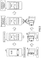
- Fig. 3 is a state transition diagram for describing a case where the communication terminal 20 is moved away from the digital camera 30 in the middle of connection processing.
- the collapsible lens 310 is projected or the power lamp 320 is turned on, and thus there is a possibility that the user understands that the connection processing has succeeded and then moves the communication terminal 20 away from the digital camera 30.
- NFC cannot be performed.
- the communication terminal 20 cannot acquire connection information required for the Wi-Fi communication connection or information of an application to be activated.
- the communication terminal 20 cannot activate the application and establish a Wi-Fi connection, and thus cannot execute the linkage function.
- the digital camera 10 performs power-on control in response to NFC when the communication terminal 20 comes close thereto, but does not perform an imaging preparation operation such as projecting a collapsible lens 13 or turning a power lamp 12 on.
- the digital camera 10 after the power-on control is performed and after transmission of the connection information required to establish the Wi-Fi communication connection and the like is completed, the digital camera 10 according to the present embodiment performs the imaging preparation operation such as projecting the collapsible lens 13 or turning the power lamp 12 on.
- the communication terminal 20 After the transmission of the Wi-Fi connection information and the like is completed, if the communication terminal 20 is moved away from the digital camera 30, the communication terminal 20 can continue to perform the series of operations, because the information required for activation of the application and a Wi-Fi connection is already acquired from the digital camera 30.
- Fig. 4 is a block configuration diagram illustrating an example of a basic configuration of the digital camera 10 according to the present embodiment.
- the digital camera 10 includes a control part 100, an operation input part 102, the power lamp 12, an imaging part 104, an image processing part 106, a recording/reading part 107, a recording medium 109, a display part 110, a speaker 111, a power supply part 113, a time management part 114, a storage part 115, a GPS positioning part 116, a gyroscope 117, the NFC part 120, and a Wi-Fi communication part 122.
- the control part 100 controls configurations of the digital camera 10. For example, as illustrated in Fig. 4 , the control part 100 outputs control signals, which correspond to an operation signal output from the operation input part 102, to the respective configurations and performs imaging control, image processing control, recording control, display control, and the like. Further, the control part 100 according to the present embodiment also functions as a communication control part that controls the NFC part 120 and the Wi-Fi communication part 122.
- control part 100 outputs a power-supply control signal to the power supply part 113 and switches power-on/off of the digital camera 10. Specifically, the control part 100 performs power-on control when detecting, by the NFC part 120, a radio signal in an NFC band that corresponds to a polling command from an external device. After the power is on, the control part 100 then transmits connection information (ID, PassKey, and the like) for performing connection with the external device (for example, the communication terminal 20) by wireless communication (for example, Wi-Fi communication) from the NFC part 120 to the external device. When the transmission of the connection information is completed, the control part 100 performs control such that the imaging preparation operation is performed.
- connection information ID, PassKey, and the like
- the imaging preparation operation represents an operation involving a change in appearance of the digital camera 10 or a notification of activation to the user.
- the imaging preparation operation involving a change in appearance is a drive operation of projecting the collapsible lens 13, for example.
- the imaging preparation operation involving a notification of activation to the user is an operation of reproducing a start-up sound from the speaker 111 or an operation of emitting light from the power lamp 12, for example. With this operation, the projection of the collapsible lens 13 or the like is not performed before the transmission of the connection information is completed, and thus it is possible to prevent the user from understanding that the connection has succeeded and moving the communication terminal 20 away from the digital camera 10 in the middle of the Wi-Fi connection processing.
- control part 100 performs control such that information for specifying an application to be activated in the external device (for example, package name) is transmitted from the NFC part 120 together with the connection information.
- information for specifying an application to be activated in the external device for example, package name
- control part 100 After the control part 100 turns on the digital camera 10 and when the transmission of the connection information is not completed within a predetermined period of time, the control part 100 performs control such that the digital camera 10 is powered off.
- control part 100 detects not a radio signal corresponding to a polling command from the external device but a press of the power button 15 by the user, the power button 15 being illustrated in Fig. 1 , the control part 100 performs control such that the power-on control of the digital camera 10 and the imaging preparation operation are normally performed.
- the operation input part 102 detects an operation input by the user and outputs the operation input as an operation signal to the control part 100.
- the operation input part 102 may be a button formed by a physical configuration (shutter button 14, power button 15, mode switch, menu button, operating lever, or the like) or may be a touch panel for detecting a touch operation onto an operation screen.
- the imaging part 104 is a signal conversion part such as a CCD (Charge Coupled Device) or a CMOS (Complementary Metal Oxide Semiconductor), in which a subject image is formed by an optical system.
- An imaging lens included in the optical system may be the collapsible lens 13 as illustrated in Fig. 1 .
- the subject image is converted into an electrical image signal by the signal conversion part.
- the image signal (captured image) converted by the imaging part 104 is transmitted to the display part 110 or the recording medium 109 via the image processing part 106 and the like.
- the image processing part 106 processes the image signal (captured image) output from the imaging part 104.
- the image processing part 106 performs, for example, noise removal, color compensation, or edge detection as necessary. Further, the image processing part 106 outputs the image signal (captured image), which is output from the imaging part 104, to the display control part 108 and/or the recording/reading part 107.
- the display control part 108 controls generation of screen to be displayed on the display part 110 or display of the display part 110.
- the display control part 108 performs generation of a display screen and display control according to the control signal output from the control part 100. Further, the display control part 108 performs control to display the captured image output from the image processing part 106 or a captured image output from the recording/reading part 107 on the display part 110.
- the display part 110 is, for example, a display device such as a liquid crystal display (LCD) device or an OLED (Organic Light Emitting Diode) device.
- a display device such as a liquid crystal display (LCD) device or an OLED (Organic Light Emitting Diode) device.
- LCD liquid crystal display
- OLED Organic Light Emitting Diode
- the recording/reading part 107 records the image signal (captured image) output from the image processing part 106 on the recording medium 109 or reads the captured image recorded on the recording medium 109, according to a timing at which the shutter button 14 is pressed, for example. Further, the recording/reading part 107 may compress the captured image and then record the resultant captured image on the recording medium 109. Further, when compressed data is read from the recording medium 109, the compressed data is combined and then output to the display control part 108.
- the recording medium 109 is a memory card in which the captured image is written, or the like.
- the power supply part 113 includes a battery and a power supply circuit and switches power-on/off according to a power-supply control signal output from the control part 100. Further, the power supply part 113 supplies power to the configurations of the digital camera 10.
- the time management part 114 is an example of an acquisition part that acquires time information, and more specifically, includes a clock circuit and manages year, month, and day and hour, minute, and second.
- the time information acquired by the time management part 114 is added to the captured image, as a record of an imaging time of day.
- the storage part 115 is a recording medium such as a RAM (Random Access Memory) or a ROM (Read Only Memory).
- the RAM is used as a work area of the control part 100, for example. Further, in the ROM, for example, programs for the control part 100 to perform the above-mentioned power-on/off control, imaging preparation operation control, and communication control, and the like are written.
- the GPS (Global Positioning System) positioning part 116 receives radio waves from a GPS satellite and determines a position where the digital camera 10 is present (current position). It should be noted that the GPS positioning part 116 is an example of a position information acquisition part that acquires current position information based on a signal acquired from the outside, and the example of the position information acquisition part is not limited to the GPS positioning part 116. For example, the position information acquisition part may acquire the current position information through Wi-Fi, transmitting and receiving with respect to a mobile phone, a PHS, a smartphone, or the like, or near field communication.
- the gyroscope 117 has a function of detecting a velocity (angular velocity) in which a rotation angle about a Z axis changes, or detecting an angular velocity about a Y axis, when the digital camera 10 is turning. Further, the digital camera 10 may include, in addition to the gyroscope 117, a three-axis acceleration sensor having a function of detecting an acceleration along an X axis, an acceleration along the Y axis, and an acceleration along the Z axis as voltage values.
- the NFC part 120 is an interface that cooperates with the NFC antenna 121 to perform contactless communication with an adjacent external device (for example, communication terminal 20) according to the control by the control part 100.
- the NFC part 120 transmits radio waves that reach a close range of approximately 3 cm to 10 cm, or depending on the design, approximately 7 mm, from the NFC antenna 121, and performs the NFC with an external device included within the radio wave reach range.
- the NFC part 120 transmits connection information (Wi-Fi Configuration) for an automatic connection to Wi-Fi and an AAR (Android Application Record) according to a check command from the external device.
- Wi-Fi Configuration includes an SSID (Service Set Identifier) for a Wi-Fi connection, a PassKey (encryption key), and the like.
- the Wi-Fi communication part 122 is an interface that cooperates with a Wi-Fi antenna 123 to perform wireless communication with a surrounding external device (for example, communication terminal 20) according to the control by the control part 100.
- the Wi-Fi communication part 122 performs Wi-Fi authentication in response to a Wi-Fi connection request from the external device and performs processing of establishing a Wi-Fi communication connection with the external device.
- Fig. 5 is a flowchart illustrating the operation processing of the digital camera 10 according to the present embodiment.
- the NFC part 120 detects an RF (radio signal) in an NFC band from the outside.
- a radio signal corresponds to a polling command that is transmitted from the communication terminal 20.
- the radio signal is detected with a frequency detector for a radio signal in the NFC band, the frequency detector being included in the NFC part 120, and thus the command is not decoded at this point of time.
- the NFC part 120 recognizes that the RF in the NFC band is detected.
- Step S106 when detecting the radio signal in the NFC band (S103/Yes), in Step S106, the control part 100 outputs a power-supply control signal to the power supply part 113 such that the digital camera 10 in the power-off state is powered on. In this case, the control part 100 does not perform an imaging preparation operation such as projecting the collapsible lens 13.
- Step S109 the control part 100 activates a timer for waiting for the NFC by using the time management part 114.
- Step S112 the control part 100 determines whether transmission of response data by the NFC in response to the check command from the outside is completed or not.
- the response data transmitted by the NFC in response to the check command is the above-mentioned Wi-Fi Config and AAR.
- Step S115 the control part 100 performs an imaging preparation operation such as projecting the collapsible lens 13.
- Step S118 the control part 100 starts a camera function.
- the control part 100 displays a through image on the display part 110.
- the through image is obtained by converting a subject image that is formed by the optical system including the collapsible lens 13 into an electrical image signal.
- the control part 100 establishes a Wi-Fi connection with the external device and executes the linkage function with the external device.
- Step S124 the control part 100 outputs a power-supply control signal to the power supply part 113 such that the digital camera 10 is powered off.
- the digital camera 10 reacts to radio waves in the same bandwidth as a polling command, which is transmitted from wireless devices (automatic turnstile, automatic vending machine, automatic authentication gate, etc.) other than a predetermined communication terminal 20 implementing the linkage function, and is powered on due to malfunction, the digital camera 10 can be powered off after a predetermined period of time. Further, it is possible to cut wasteful electric power consumption.
- the imaging preparation operation such as projecting the collapsible lens 13 is not performed.
- the imaging preparation operation such as projecting the collapsible lens 13 is not performed.
- Fig. 6 illustrates a state transition diagram for describing the above-mentioned series of operations of the digital camera 10 in association with the operation of the communication terminal 20.
- the digital camera 10 is powered on by NFC.
- the imaging preparation operation such as projecting the collapsible lens 13 is not performed.
- the communication terminal 20 receives Wi-Fi connection information and the like (Wi-Fi Config and AAR) from the digital camera 10 by the NFC.
- Wi-Fi Config and AAR Wi-Fi Config and AAR
- the digital camera 10 performs the imaging preparation operation such as projecting the collapsible lens 13 or emitting light from the power lamp 12.
- a predetermined application is activated according to the AAR, and a Wi-Fi connection request is made to the digital camera 10 by using the Wi-Fi Config.
- the Wi-Fi connection is completed between the communication terminal 20 and the digital camera 10
- the linkage function using the Wi-Fi communication is executed.
- the digital camera 10 since the digital camera 10 according to the present embodiment projects the collapsible lens 13, or the like, after the transmission of the connection information and the like is completed, if the user understands that the connection processing has succeeded and moves the communication terminal 20 away at this point of time, the communication terminal 20 can perform the series of operations to the execution of the linkage function.
- the digital camera 10 performs power-off control, and thus it is possible to cut wasteful electric power consumption in the case where the digital camera 10 is activated due to malfunction. Further, even if the digital camera 10 is powered on due to malfunction, the collapsible lens 13 is not projected. Thus, it is possible to prevent the lens from being damaged by the collapsible lens 13 projected in a state of being stored in the casing, when the digital camera 10 is powered on.
- Step S130 the control part 100 performs power-on normally and the imaging preparation operation such as projecting the collapsible lens 13.
- Step S133 the control part 100 starts a camera function.
- Fig. 7 is a sequence diagram illustrating the operation processing of the control system according to the present embodiment.
- Step S203 the communication terminal 20 transmits a polling command by NFC.
- Step S206 when the NFC antenna 121 of the digital camera 10 is included within a predetermined radio wave reach range (for example, approximately 7 mm) from the NFC antenna of the communication terminal 20, the NFC part 120 detects the polling command. It should be noted that the NFC part 120 detects the command with a frequency detector for a radio signal in the NFC band, as described above, and thus the NFC part 120 cannot recognize what command the detected radio signal represents, and recognizes that the RF in the NFC band is detected.
- a predetermined radio wave reach range for example, approximately 7 mm
- Step S209 the NFC part 120 is driven in response to the detection of the RF in the NFC band and notifies the control part 100 of the detection.
- Step S212 the control part 100 outputs a power-supply control signal to the power supply part 113 in response to the notification of the detection by the NFC part 120 and performs the power-on control.
- Step S215 the NFC part 120 transmits a command response by the NFC, in response to the detection of the RF in the NFC band.
- Step S218, the communication terminal 20 detects the command response from the digital camera 10 and thus finds the other party of the NFC, and then transmits a check command in order to acquire predetermined information.
- Step S221 the NFC part 120 of the digital camera 10 outputs the check command, which is received by the NFC, to the control part 100.
- Step S224 the control part 100 outputs response data to the NFC part 120 in response to the check command.
- the response data includes the Wi-Fi Config and the AAR.
- Step S227 the NFC part 120 transmits the response data to the communication terminal 20 by the NFC.
- S218 to S227 described above may be performed a plurality of times and the response data may be transmitted in a plurality of times.
- Step S233 the communication terminal 20 activates a predetermined application according to the received AAR.
- Step S236 the communication terminal 20 makes a Wi-Fi connection request to the digital camera 10 by using the received Wi-Fi Config.
- Step S239 the Wi-Fi communication part 122 of the digital camera outputs the connection request, which is received from the communication terminal 20, to the control part 100.
- Step S242 the control part 100 performs Wi-Fi authentication. It should be noted that the Wi-Fi authentication may be performed by the Wi-Fi communication part 122.
- Step S245 the control part 100 outputs an authentication result to the Wi-Fi communication part 122.
- Step S248 the Wi-Fi communication part 122 transmits the authentication result to the communication terminal 20.
- Step S251 when the authentication succeeds, the Wi-Fi connection is completed.
- Step S254 the linkage function using the Wi-Fi communication is executed between the communication terminal 20 and the digital camera 10.
- the above embodiment has described the digital camera 10 used separately from the communication terminal 20, as an example.
- an imaging unit 1 including a digital camera that can be used by being installed to the communication terminal 20 will be described.
- a subject side is a front side
- the photographer side is a rear side.
- front and rear, up and down, and right and left directions described below are for convenience of description, and the execution of the present technology is not limited to those directions.
- Figs. 8 and 9 each illustrate a state in which the imaging unit 1 is installed to the communication terminal 20.
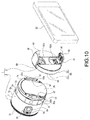
- Fig. 10 is a perspective view illustrating a digital camera 2, an adaptor 3, and the communication terminal 20 that form the imaging unit 1.
- Fig. 11 is a perspective view of the digital camera 2 in an activated state.
- Figs. 12 to 16 are a plan view, a bottom view, a left side view, and a right side view of the digital camera 2.
- Figs. 16 and 17 are each a perspective view of the adaptor 3.
- the imaging unit 1 will be described with reference to those figures.
- the imaging unit 1 includes the digital camera 2 and the adaptor 3 (see Figs. 8 to 10 ).
- the adaptor 3 is attachable to and detachable from a rear surface of the digital camera 2.
- the imaging unit 1 may have an integrated configuration in which the adaptor 3 is integrally formed with the digital camera 2 at a rear end of the digital camera 2.
- the digital camera 2 has a communication function capable of transmitting and receiving image data or the like to and from the communication terminal 20.
- the adaptor 3 is attachable to and detachable from the communication terminal 20.
- the digital camera 2 includes an outer barrel 7, a plurality of lens groups disposed inside the outer barrel 7, and an imaging element (not illustrated) located on the rear side of the lens groups (see Figs. 8 to 11 ).
- an imaging element located on the rear side of the lens groups (see Figs. 8 to 11 ).
- light incorporated via the lens groups is subjected to photoelectric conversion in the imaging element. Therefore, the digital camera 2 can capture image or video.
- the outer barrel 7 includes a circumferential surface part 7a that is formed in a substantially cylindrical shape extending from the front side to the rear side, an overhang part 7b that overhangs inward from a front end of the circumferential surface part 7a, and a rear surface part 7c that closes the circumferential surface part 7a from the rear side.
- Inner barrels 8 and 8 that can be moved in the front and rear direction are supported inside the outer barrel 7. Therefore, the digital camera 2 is turned to an image capture state (see Fig. 11 ) when the inner barrels 8 and 8 protrude forward with respect to the outer barrel 7, and is turned to a collapsible state (see Fig. 9 ) when the inner barrels 8 and 8 that have protruded forward are withdrawn backward and are stored in the outer barrel 7.
- a light passing hole 8a with a substantially rectangular shape is formed in a front surface part of the inner barrel 8 that is located on the innermost side (see Fig. 11 ).
- Lens barriers 9 and 9 are supported on a rear surface side of the front surface part of the inner barrel 8 that is located on the innermost side, so as to be freely opened and closed.
- the lens barriers 9 and 9 are closed in a collapsible state and are opened in an image capture state by an opening and closing mechanism (not illustrated). Therefore, in the collapsible state, the light passing hole 8a of the inner barrel 8 is closed by the lens barriers 9 and 9 (see Fig. 9 ) and, in the image capture state, the light passing hole 8a is opened by the lens barriers 9 and 9 (see Fig. 11 ).
- a plurality of lens groups including an image capture lens 30 (see Fig. 11 ) located on the frontmost side are disposed separately from each other in the optical axis direction inside the digital camera 2, and if the light passing hole 8a is opened by the lens barriers 9 and 9, light is incident to the image capture lens 30 from the outside.
- An operation ring 31 is rotatably supported at the front end of the outer barrel 7 (see Fig. 9 ). When the operation ring 31 is operated, manual focusing or zooming are performed and the lens groups are moved in the optical axis direction.
- the operation ring 31 is provided around the outer barrel 7 at the front end of the outer barrel 7, and thus a user easily performs a rotation operation of the operation ring 31.
- the surface of the operation ring 31 is formed as a sawtooth grip part, which is also suitable to improve the operability of a rotation operation.
- the operation ring 31 can switch operation content between a manual focusing operation and a zooming operation on the basis of the control by wireless communication, in response to a user's operation from the communication terminal 20. Therefore, the operation ring 31 can be used as an operation part of a focusing operation and a zooming operation in accordance with a user's preference or circumstances.
- Coupling parts 32 and 32 that protrude backward are provided at positions opposite to each other, 180° apart on an outer circumference of the rear surface part 7c of the outer barrel 7 (see Figs. 10 and 12 to 15 ).
- Locking protrusions 32a and 32a that protrude outward separately in a circumferential direction are respectively provided at the coupling parts 32. This forms an engagement structure engaged with coupling recess parts 56a and 56a and locking pieces 53a and 53a of the adaptor 3 to be described later.
- a lock pin 33 is supported movably in the front and rear direction in the vicinity of the coupling part 32 of the rear surface part 7c, and the lock pin 33 is biased backward by a spring (not illustrated).
- An unlock lever 2a is disposed at the rear end of the circumferential surface part 7a of the outer barrel 7 (see Fig. 15 ). The unlock lever 2a is operated, and thus the lock pin 33 is drawn into the outer barrel 7.
- a battery lid 2b is disposed at a portion between the coupling parts 32 and 32 of the rear surface part 7c of the outer barrel 7 (see Fig. 10 ).
- a battery loading portion in which a battery is stored is formed inside the battery lid 2b in the digital camera 2.
- the battery lid 2b is opened and closed, and thus a battery (not illustrated) can be installed in and removed from the storage portion.
- the coupling parts 32 and 32 are formed on the outer circumference of the rear surface part 7c, and thus a gap between the coupling parts 32 and 32 can be used for disposing the battery lid 2b and the battery loading portion.
- the coupling parts 32 and 32 are formed on the outer circumference of the rear surface part 7c, which does not impede ensuring of a space for storing the battery.
- Microphones 2c and 2c and a power button 2d are disposed separately from each other in the front and rear direction at the upper end of the circumferential surface part 7a of the outer barrel 7 (see Figs. 9 , 10 , and 12 ).
- the microphones 2c and 2c are parts for inputting external sound.
- a position in which external sound are least likely to be interrupted is the circumferential surface part 7a of the outer barrel 7. Therefore, it is suitable to collect external sound by disposing the microphones 2c and 2c in the circumferential surface part 7a.
- the microphones 2c and 2c are provided at the upper end of the circumferential surface part 7a, the microphones 2c and 2c are hardly blocked when a user grasps the outer barrel 7, and thus are suitable for the input of external sound.
- the illustrated portions of the microphones 2c and 2c are visually recognized as microphone holes from the outside.
- the microphones 2c and 2c are disposed inward of the circumferential surface part 7a, but the microphone holes (2c, 2c) that guide external sound to the two microphones that input at least external sound are formed on the circumferential surface part 7a at bilaterally symmetric positions. Being bilaterally symmetric is suitable to collect stereophonic sound on the right and left sides.
- the power button 2d is disposed such that the surface thereof does not protrude from a surface forming the circumferential surface part 7a.
- the power button 2d is formed to be flush with the circumferential surface part 7a.
- the surface of the power button 2d may be lowered below the circumferential surface part 7a.
- the power button 2d does not protrude from the circumferential surface part 7a, and thus it is suitable to prevent an erroneous operation of the power button 2d.
- a tripod hole 2e is formed at the lower end of the circumferential surface part 7a of the outer barrel 7 (see Fig. 13 ).
- the tripod hole 2e is a hole for coupling the digital camera 2 to a tripod (not illustrated) when an image capture operation is performed, for example.
- the tripod hole 2e is formed at the lower end of the circumferential surface part 7a, and thus a balance when the tripod is attached can be achieved.
- Rolling prevention protrusions 2f and 2f are provided on the right and left sides of the tripod hole 2e at the lower end of the circumferential surface part 7a of the outer barrel 7 (see Figs. 10 and 13 ).
- the rolling prevention protrusions 2f and 2f protrude slightly downward.
- the digital camera 2 is prevented from rolling by the rolling prevention protrusions 2f and 2f when the digital camera 2 is placed on a desk, a table, or the like, and thus it is possible to prevent damage or a failure by the digital camera 2 falling off.
- the rolling prevention protrusions 2f are useful.
- a zoom switch 2g and a shutter button (image capture button) 2h are arranged close to each other in the front and rear direction at the left end of the circumferential surface part 7a of the outer barrel 7 (see Figs. 10 and 14 ).
- zoom switch 2g When the zoom switch 2g is operated, zooming is performed between telephoto and a wide angle.
- the shutter button 2h is operated, an image of a subject is captured.
- the zoom switch 2g and the shutter button 2h are disposed close to each other, the user easily performs the series of operations of adjusting the angle of view by zooming and performing a shutter operation.
- the zoom switch 2g and the shutter button 2h may be arranged not only in the front and rear direction but also in positions close to each other in a state of being arranged in the up and down or oblique direction.
- the shutter button 2h and the zoom switch 2g are disposed on the same member 2k.
- the member 2k forms a part of the circumferential surface part 7a together with the outer barrel 7.
- the shutter button 2h may be, for example, an operation part for automatic focusing in a half depressing operation, and for imaging or photographing a subject in a full depressing operation.
- the digital camera 2 is used singly, there is no display part (that is, communication terminal 20), and thus a focusing operation is difficult to perform.
- automatic focusing is performed by half depressing of the shutter button 2h, it is possible to provide an operation that is intuitively easily understandable to a user.
- a sound output part is provided so as to output an electronic sound or the like during the automatic focusing operation, this is suitable for a user to recognize the operation.
- the zoom switch 2g is formed in the shape of a zoom lever as illustrated in the figures. The zooming operation is performed by operating the lever, and thus the operability is improved. It should be noted that the zoom switch 2g may be formed in the shape of a press button such as wide button/telephoto button. Further, two zoom switches formed in the shape of a button and a lever may be provided.
- the zoom switch 2g and the shutter button 2h are disposed at the left end of the circumferential surface part 7a, an operating finger is naturally disposed around the zoom switch 2g and the shutter button 2h when the digital camera 2 is grasped from the lower side during an image capture operation, and thus it is possible to improve the convenience for a user in using the digital camera 2 through the improvement of operability.
- the zoom switch 2g and the shutter button 2h are disposed at the left end of the circumferential surface part 7a, and are thus located so as to be separated from the microphones 2c and 2c provided at the upper end of the circumferential surface part 7a. Accordingly, sound emitted when a user operates the shutter button 2h or the zoom switch 2g are not picked up as much as possible by the microphones 2c and 2c.
- the zoom switch 2g and the above-mentioned operation ring 31 are prepared. Accordingly, a user can select a zooming operation method in accordance with circumstances or a preference, and thus the operability is improved.
- the shutter button 2h and the power button 2d are disposed in positions different in a circumferential direction on the circumferential surface part 7a to be separated from each other on the upper portion and the side portion of the circumferential surface part, it is easy to prevent an error in the power supply operation and the image capture operation. It should be noted that the shutter button 2h and the power button 2d may be separated from each other on the right side and the left side of the circumferential surface part 7a. However, considering that the upper portion of the circumferential surface part 7a is more adequate to the power button 2d as described above, it is adequate to dispose the shutter button 2h on the side portion (right side or left side) of the circumferential surface part.
- a cover body 2i is disposed on the rear side of the shutter button 2h at the left end of the circumferential surface part 7a of the outer barrel 7.
- an external connection terminal such as a USB (Universal Serial Bus) and a memory card slot (not illustrated) are provided inside the cover body 2i. Therefore, the cover body 2i is opened, and thus connection to an external device and installation of a memory card can be performed. Further, through the connection to an external device or the installation of a memory card, an image or a video captured by the digital camera 2 can be recorded in the external device or the memory card.
- USB Universal Serial Bus
- a display part 2j formed by a liquid crystal panel or the like is disposed at the right end of the circumferential surface part 7a of the outer barrel 7 (see Fig. 15 ).
- the display part 2j displays a residual quantity of a battery or whether or not a memory card is inserted into the memory card slot.
- the display part 2j is not used for displaying a captured image.
- the display part 2j Since the display part 2j is disposed, it is possible to check a residual quantity of a battery or whether or not a memory card is inserted into the memory card slot, from the outside of the digital camera 2, and to thus improve the convenience for a user in using the digital camera 2.
- the digital camera 2 has a wireless communication function.
- wireless communication for example, it is possible to perform various operations such as displaying or preserving an image or a video captured by the digital camera 2 on the communication terminal 20, executing an image capture function of the digital camera 2 by operating the communication terminal 20, and executing the zooming function of the digital camera 2 by operating the communication terminal 20.
- an NFC part (NFC tag) is mounted in the inside close to the upper end of the circumferential surface part 7a in the outer barrel 7, and performs contactless communication with an NFC part mounted in the communication terminal 20.
- a WIFI communication part is provided for transmission of a captured image or the like, and performs wireless communication with a WIFI communication part mounted in the communication terminal 20.
- the digital camera 2 may not only be powered on by operating the power button 2d as described above, but also be powered on through the NFC from the communication terminal 20 side. For example, if the NFC is established, the digital camera 2 is powered on. For example, when the NFC function is displayed in the vicinity of the power button 2d, such as the upper end of the circumferential surface part 7a, a user can easily understand a power-on operation.
- the NFC part when the NFC part is disposed on the upper side in the outer barrel 7, in a case where the digital camera 2 is used by attaching a tripod to the above-described tripod hole 2e, the NFC part becomes as close to the communication terminal 20 as possible easily, which is thus advantageous in contactless communication.
- the user considering a state in which the digital camera 2 is placed on a mounting surface such as a desk, the user generally moves the communication terminal 20 close to the digital camera 2 from above. Therefore, when the NFC part is disposed on the upper side in the outer barrel 7, this arrangement is suitable for near field wireless communication in such a usage mode as well.
- the position at which the NFC part is disposed in the digital camera 2 is not the upper side in the outer barrel 7. It is desirable not to dispose the NFC part on at least the rear surface side of the outer barrel 7, that is, in a position close to the rear surface part 7c side. If the NFC part that performs near field wireless communication is disposed on the rear surface side, when the digital camera 2 is attached to the communication terminal 20 through the adaptor 3 as illustrated in Figs. 8 and 9 , the NFC part is constantly close to the NFC part on the communication terminal 20 side and may constantly perform polling. Therefore, the NFC part is desirably disposed in a position other than the rear surface side of the outer barrel 7.
- the adaptor 3 includes respective necessary parts disposed inside and outside a casing 50 (see Figs. 16 and 17 ).
- the casing 50 is formed by coupling a base body 51 located on the front side to a cover body 52 located on the rear side.
- the base body 51 includes a base surface part 53 that is formed in a disc shape, and projections 56 and 56 that protrude backward from the base surface part 53 (see Fig. 23).
- the projections 56 and 56 are formed in shapes that protrude from positions opposite to each other, 180° apart on the outer circumference of the base surface part 53 and that extend in the circumferential direction at both of right and left ends of the base surface part 53.
- the projection 56 is opened forward, and an inner space of the projection 56 is formed as the coupling recess part 56a (see Fig. 16 ).
- Each of the locking pieces 53a and 53a, ... that covers a portion of the coupling recess part 56a from the front side is provided on the outer circumference of the base surface part 53.
- a locked hole 53b that communicates with the coupling recess part 56a is formed in the base surface part 53.
- the cover body 52 has exteriors that are formed in a circular shape except for a portion thereof.
- a storage recess part 52c that is opened backward and upward and a storage recess part 52d that is opened backward and downward are formed therein (see Fig. 10 ).
- the adaptor 3 is provided with a first attached body 68 and a second attached body 63 to be installed to the communication terminal 20.
- the first attached body 68 is stored in the storage recess part 52c and can take a storage position (see Fig. 17 ) of being closed for the base body 51. Further, the first attached body 68 can take a holding position (see Fig. 10 ) of being opened for the base body 51. The first attached body 68 is rotatably moved between the storage position and the holding position.
- the first attached body 68 is in a state of protruding backward from the cover body 52 at the holding position.
- the second attached body 63 is stored in the storage recess part 52d and is rotatably moved between a storage position (see Fig. 17 ) of being closed for the base body 51 and a holding position (see Fig. 10 ) of being opened for the base body 51.
- the second attached body 63 is in a state of protruding backward from the cover body 52 at the holding position.
- the second attached body 63 is in a state of being stored for the base body 51 in the storage position and in a state of protruding backward from the cover body 52 in the holding position, as in the case of the first attached body 68.
- the adaptor 3 is coupled to the digital camera 2 as follows.
- the coupling parts 32 and 32 of the digital camera 2 are respectively inserted into the coupling recess parts 56a and 56a formed in the base body 51 of the adaptor 3.
- the adaptor 3 is rotated with respect to the digital camera 2.
- the locking pieces 53a and 53a of the adaptor 3 are respectively engaged with the locking protrusions 32a and 32a of the digital camera 2, and thus a movement of the adaptor 3 with respect to the digital camera 2 is restricted in the front and rear direction.
- the locking protrusions 32a and 32a form a state of being engaged with the locking pieces 53a and 53a of the adaptor 3.
- the lock pin 33 of the digital camera 2 is pressed by the base body 51, and the lock pin 33 is drawn into the outer barrel 7 against a biasing force of the spring so that the adaptor 3 is rotated to a predetermined position and the locked hole 53b matches the lock pin 33.
- the lock pin 33 is made to protrude from the outer barrel 7 by the spring and is thus inserted into the locked hole 53b.
- the digital camera 2 and the adaptor 3 are relatively rotated via the coupling parts 32 and 32, and thus the digital camera 2 and the adaptor 3 can be easily coupled to each other. Further, the coupled state is kept by the lock pin 33.
- the unlock lever 2a is operated so that the lock pin 33 is drawn into the outer barrel 7, and the adaptor 3 is rotated about the digital camera 2 in a direction opposite to the time of the coupling in the unlocked state, thereby performing decoupling of the adaptor 3 from the digital camera 2. If the adaptor 3 is rotated about the digital camera 2 in a direction opposite to the time of the coupling, the engagement state between the locking pieces 53a and 53a and the locking protrusions 32a and 32a of the digital camera 2 is canceled. The adaptor 3 is moved backward with respect to the digital camera 2 in this state, and the coupling parts 32 and 32 are extracted from the coupling recess parts 56a and 56a, thereby decoupling the adaptor 3 from the digital camera 2.
- the adaptor 3 is attached to the communication terminal 20 as follows.
- the first attached body 68 and the second attached body 63 are respectively extracted from the storage recess parts 52c and 52d of the cover body 52 and are rotatably moved to the respective holding positions.
- the first attached body 68 is then grasped and moved upward.
- the first attached body 68 is attached to a slider (not illustrated) inside the adaptor 3 and is movable upward. Further, a spring is attached to the slider, and the first attached body 68 is constantly biased in a direction of being close to the second attached body 63.
- the first attached body 68 is moved so as to be extracted upward, the first attached body 68 is gradually spaced apart from the second attached body 63. The first attached body 68 is moved upward to a position corresponding to the size of the communication terminal 20 to be attached.
- the communication terminal 20 is then pinched by the first attached body 68 and the second attached body 63, and thus the adaptor 3 is attached to the communication terminal 20 ( Figs. 8 and 9 ).
- the first attached body 68 is biased to the second attached body 63 in a direction of being close thereto, and elastic bodies 61 and 61 (see Figs. 8 and 10 ) provided to the first attached body 68 and the second attached body 63 are in close contact with the communication terminal 20.
- a holding protrusion 60 of the first attached body 68 and a holding protrusion 65 of the second attached body 63 are in a state of going around to the rear surface side of the communication terminal 20. Therefore, the adaptor 3 is prevented from falling forward from the communication terminal 20.
- the adaptor 3 has a configuration in which the second attached body 63 is set to a fixed position, and the first attached body 68 side is extended. Only the first attached body 68 that is an upper side is extended and contracted, and a gap between the first attached body 68 and the second attached body 63 is adjusted. Therefore, an imaging optical axis of the digital camera 2 is located at a position that is equal to or lower than the central point in the height direction (the short side direction of the casing of the communication terminal 20) of the display panel of the communication terminal 20. In addition, a bottom position of the digital camera 2 and a bottom position of the communication terminal 20 substantially match each other regardless of the size of the communication terminal 20.
- a user can easily stably hold the communication terminal 20 attached with the imaging unit 1 regardless of the size of the communication terminal 20.
- the communication terminal 20 attached with the imaging unit 1 is placed on a desk or the like as it is, a posture thereof is stable, and thus the communication terminal 20 attached therewith is also suitable for imaging in this state.
- the second attached body 63 is set to a fixed position, and thus there is an advantage in that an attachment state of the adaptor 3 to the communication terminal 20 is stable.
- the adaptor 3 is provided with a mark 68 that presents an upwardly extending configuration of the first attached body 68 side. With the mark 68, the user can recognize that the position of the first attached body 68 upwardly extends and easily understand how to attach the adaptor 3 when being attached to the communication terminal 20, thus improving the usability.
- the first attached body 68 is grasped and moved upward so that the communication terminal 20 is extracted between the first attached body 68 and the second attached body 63, thereby removing the adaptor 3 from the communication terminal 20. If the upward force given to the first attached body 68 is removed after the communication terminal 20 is extracted between the first attached body 68 and the second attached body 63, the first attached body 68 is moved downward by the biasing force, and the first attached body 68 is returned to a state before being attached to the communication terminal 20.
- the structure of the imaging unit 1 by the digital camera 2 and the adaptor 3 has been described up to here, but the structure of the imaging unit 1 attached to the communication terminal 20 for use in the manner described above is variously conceived.
- the digital camera 2 has been described as one having a substantially cylindrical shape, but the shape of the digital camera 2 is not limited thereto.
- the shape of the outer casing may be a substantially rectangular parallelepiped.
- a substantially elliptic cylinder, a substantially cylindrical shape having a partially notched circle, and the like are also conceivable.
- the internal constitution of the digital camera 2 can be assumed to be roughly the same as that of Fig. 4 .
- the display part 110 is the display part 2j provided to the circumferential surface part 7a, which is not for displaying a captured image.
- Fig. 19 is a state transition diagram for describing the above-mentioned series of operations of the imaging unit 1 in association with the operation of the communication terminal 20.
- the digital camera 2 is powered on (power-on) by NFC. It should be noted that the NFC is performed not only when the communication terminal 20 is simply moved closer to the imaging unit 1 but also when the digital camera 2 is installed to the communication terminal 20 by using the adaptor 3 as described above.
- the imaging preparation operation such as projecting the inner barrel 8 is not performed at the point of time at which the communication terminal 20 is moved closer to the imaging unit 1 or the digital camera 2 is installed to the communication terminal 20.
- the communication terminal 20 receives Wi-Fi connection information and the like (Wi-Fi Config and AAR) from the digital camera 2 by the NFC.
- Wi-Fi Config and AAR Wi-Fi Config and AAR
- the digital camera 2 performs the imaging preparation operation such as projecting the inner barrel 8.
- a predetermined application is activated according to the AAR and a Wi-Fi connection request is made to the digital camera 2 by using the Wi-Fi Config.
- a Wi-Fi connection is completed between the communication terminal 20 and the digital camera 2
- a linkage function using Wi-Fi communication is executed.
- the digital camera 2 performs power-off control, and thus it is possible to cut wasteful electric power consumption in the case where the digital camera 2 is activated due to malfunction. Further, even if the digital camera 2 is powered on due to malfunction, the inner barrel 8 is not projected. Thus, it is possible to prevent the lens from being damaged by the projection.
- the digital cameras 10 and 2 perform the power-on control when the communication terminal 20 comes close thereto and perform, after the transmission of the Wi-Fi connection information and the like is competed by the NFC, the imaging preparation operation such as projecting the collapsible lens 13 or turning the power lamp 12 on.
- the imaging preparation operation such as projecting the collapsible lens 13 or turning the power lamp 12 on.
- the digital camera is powered on due to malfunction, when the transmission of the Wi-Fi connection information and the like by the NFC is not completed, the digital camera is powered off. Thus, it is possible to cut wasteful electric power consumption. Further, at a point of time at which the digital camera is powered on, the collapsible lens 13 is not projected. Thus, it is possible to prevent the digital camera from being powered on due to malfunction, the collapsible lens 13 from being projected within the casing, and the lens from being damaged.
- a computer program for causing hardware such as a CPU (Central Processing Unit), a ROM, or a RAM, which is incorporated into the digital camera 10 or the communication terminal 20, to exert the function of the digital camera 10 or the communication terminal 20 can also be created.
- a computer-readable recording medium in which the computer program is stored is also provided.
- the steps in the processing of the digital camera 10 and the communication terminal 20 in this specification are not necessarily processed chronologically along the order disclosed in the attached flowcharts and sequence diagrams.
- the steps in the processing of the digital camera 10 and the communication terminal 20 may be processed in the order different from the order described as the flowcharts and sequence diagrams or processed in parallel.
- Steps S209 and S215 illustrated in Fig. 7 may be processed in parallel or may be processed in reverse order.
- Steps S233 and S236 to S251 illustrated in Fig. 7 may be processed in parallel or may be processed in reverse order.
Landscapes
- Engineering & Computer Science (AREA)
- Signal Processing (AREA)
- Multimedia (AREA)
- Computer Networks & Wireless Communication (AREA)
- Human Computer Interaction (AREA)
- Studio Devices (AREA)
- Structure And Mechanism Of Cameras (AREA)
- Camera Bodies And Camera Details Or Accessories (AREA)
- Mobile Radio Communication Systems (AREA)
- Exposure Control For Cameras (AREA)
- Details Of Cameras Including Film Mechanisms (AREA)
- Near-Field Transmission Systems (AREA)
- Facsimiles In General (AREA)
Applications Claiming Priority (6)
| Application Number | Priority Date | Filing Date | Title |
|---|---|---|---|
| JP2013169727 | 2013-08-19 | ||
| JP2013170487 | 2013-08-20 | ||
| JP2013173891 | 2013-08-23 | ||
| JP2013192269 | 2013-09-17 | ||
| JP2014013384A JP5527492B1 (ja) | 2013-08-19 | 2014-01-28 | 撮像装置、制御方法、およびプログラム |
| PCT/JP2014/070889 WO2015025725A1 (ja) | 2013-08-19 | 2014-08-07 | 撮像装置、制御方法、およびプログラム |
Publications (2)
| Publication Number | Publication Date |
|---|---|
| EP3038342A1 true EP3038342A1 (de) | 2016-06-29 |
| EP3038342A4 EP3038342A4 (de) | 2017-06-14 |
Family
ID=51175763
Family Applications (3)
| Application Number | Title | Priority Date | Filing Date |
|---|---|---|---|
| EP17196929.8A Ceased EP3288251A1 (de) | 2013-08-19 | 2014-04-25 | Abbildungsvorrichtung, steuerungsverfahren und programm |
| EP14166057.1A Not-in-force EP2840774B1 (de) | 2013-08-19 | 2014-04-25 | Abbildungsvorrichtung, Steuerverfahren und Programm |
| EP14838186.6A Withdrawn EP3038342A4 (de) | 2013-08-19 | 2014-08-07 | Abbildungsvorrichtung, steuerungsverfahren und programm |
Family Applications Before (2)
| Application Number | Title | Priority Date | Filing Date |
|---|---|---|---|
| EP17196929.8A Ceased EP3288251A1 (de) | 2013-08-19 | 2014-04-25 | Abbildungsvorrichtung, steuerungsverfahren und programm |
| EP14166057.1A Not-in-force EP2840774B1 (de) | 2013-08-19 | 2014-04-25 | Abbildungsvorrichtung, Steuerverfahren und Programm |
Country Status (8)
| Country | Link |
|---|---|
| US (4) | US9723196B2 (de) |
| EP (3) | EP3288251A1 (de) |
| JP (2) | JP5527492B1 (de) |
| CN (2) | CN103997595B (de) |
| BR (1) | BR112016002988A8 (de) |
| RU (1) | RU2669788C2 (de) |
| TW (1) | TWI482490B (de) |
| WO (1) | WO2015025725A1 (de) |
Families Citing this family (32)
| Publication number | Priority date | Publication date | Assignee | Title |
|---|---|---|---|---|
| US20150244422A1 (en) * | 2014-02-26 | 2015-08-27 | Kabushiki Kaisha Toshiba | Memory device including wireless communication function |
| JP6310339B2 (ja) * | 2014-06-25 | 2018-04-11 | オリンパス株式会社 | 撮像システム及び撮像方法 |
| BR102014016654B1 (pt) * | 2014-07-03 | 2022-03-08 | Samsung Eletrônica Da Amazônia Ltda | Sistema de dispositivo móvel com câmera removível e seu método de utilização |
| JP2016031482A (ja) | 2014-07-30 | 2016-03-07 | ソニー株式会社 | 撮像装置 |
| EP3182692B1 (de) | 2014-08-12 | 2023-12-20 | Sony Group Corporation | Informationsverarbeitungsvorrichtung, programm und informationsverarbeitungsverfahren |
| WO2016035401A1 (ja) * | 2014-09-03 | 2016-03-10 | オリンパス株式会社 | 内視鏡装置 |
| JP6423710B2 (ja) * | 2014-12-22 | 2018-11-14 | オリンパス株式会社 | 携帯機器、通信システム、通信接続方法、及び通信接続プログラム |
| US9344615B1 (en) * | 2015-01-26 | 2016-05-17 | International Business Machines Corporation | Discriminating visual recognition program for digital cameras |
| CN104618653A (zh) * | 2015-02-01 | 2015-05-13 | 深圳市芯中芯科技有限公司 | 一种新型蓝牙自拍控制装置 |
| JP6500467B2 (ja) * | 2015-02-04 | 2019-04-17 | カシオ計算機株式会社 | 撮影装置、及び送信制御方法 |
| US20160227097A1 (en) | 2015-02-04 | 2016-08-04 | Casio Computer Co., Ltd. | Data processing device that executes predetermined data processing by linking with other apparatus |
| JP6676876B2 (ja) * | 2015-03-05 | 2020-04-08 | セイコーエプソン株式会社 | 表示装置、端末装置、及び、表示システム |
| CN107210958A (zh) * | 2015-03-16 | 2017-09-26 | 奥林巴斯株式会社 | 通信装置、通信系统和通信方法 |
| US20170150032A1 (en) * | 2015-11-24 | 2017-05-25 | Ieon C. Chenn | Camera having adaptive functionality based on connection with host device |
| JP6769443B2 (ja) * | 2015-12-15 | 2020-10-14 | ソニー株式会社 | 情報処理装置、情報処理方法、およびプログラム |
| JP6672780B2 (ja) * | 2015-12-22 | 2020-03-25 | ソニー株式会社 | 情報処理装置、情報処理方法、およびプログラム |
| TWI656692B (zh) * | 2015-12-31 | 2019-04-11 | 鴻海精密工業股份有限公司 | 通訊裝置 |
| JP6746949B2 (ja) * | 2016-02-25 | 2020-08-26 | オムロン株式会社 | ハンドルロック機構、ハンドルロック装置および移動体 |
| US10507590B2 (en) * | 2016-03-14 | 2019-12-17 | Milwaukee Electric Tool Corporation | Control of a cutting tool |
| JP2018056778A (ja) * | 2016-09-28 | 2018-04-05 | カシオ計算機株式会社 | 通信制御装置、通信制御方法及びプログラム |
| JP6680186B2 (ja) * | 2016-11-10 | 2020-04-15 | 京セラドキュメントソリューションズ株式会社 | 電子機器及び電源制御プログラム |
| US20180249094A1 (en) * | 2017-02-27 | 2018-08-30 | Opkix, Inc | Wireless Camera System |
| JP6976722B2 (ja) * | 2017-06-01 | 2021-12-08 | キヤノン株式会社 | 通信装置及びその制御方法、並びに、プログラム |
| JP7122669B2 (ja) * | 2017-10-30 | 2022-08-22 | パナソニックIpマネジメント株式会社 | 撮像装置 |
| DE102020201822A1 (de) * | 2019-10-11 | 2021-04-15 | Continental Automotive Gmbh | Kamerasystem für ein Fahrzeug |
| CN111263041B (zh) | 2020-01-22 | 2021-07-20 | 维沃移动通信有限公司 | 摄像模组、电子设备及摄像模组的控制方法 |
| DE102020108962A1 (de) | 2020-03-31 | 2021-09-30 | Leica Camera Aktiengesellschaft | Mobilgerät und mobilgerätsystem |
| JP7479908B2 (ja) * | 2020-04-06 | 2024-05-09 | キヤノン株式会社 | 通信装置、通信装置の制御方法、及びプログラム |
| TWI746390B (zh) * | 2020-04-16 | 2021-11-11 | 宏達國際電子股份有限公司 | 無線信號收發裝置 |
| CN114915721A (zh) * | 2021-02-09 | 2022-08-16 | 华为技术有限公司 | 建立连接的方法与电子设备 |
| CN114915747B (zh) * | 2021-02-09 | 2024-05-03 | 华为技术有限公司 | 视频通话的方法、电子设备及可读存储介质 |
| JP7836636B1 (ja) * | 2024-09-06 | 2026-03-27 | 貴弘 高坂 | ハンドヘルド電子機器同士を結合するアダプター |
Family Cites Families (124)
| Publication number | Priority date | Publication date | Assignee | Title |
|---|---|---|---|---|
| JPS5915021A (ja) | 1982-07-05 | 1984-01-26 | 呉羽化学工業株式会社 | 包装装置 |
| GB2166893B (en) * | 1984-10-05 | 1988-03-23 | Sharp Kk | Checking memory at system power-up |
| JPS6262667A (ja) | 1985-09-12 | 1987-03-19 | Matsushita Electric Ind Co Ltd | 映像記録再生装置 |
| US5579069A (en) | 1993-12-22 | 1996-11-26 | Samsung Aerospace Industries, Ltd. | Camera with special switch assembly |
| JPH08331434A (ja) | 1995-06-01 | 1996-12-13 | Sony Corp | ビデオカメラ装置およびビデオカメラ遠隔制御装置 |
| US6369952B1 (en) * | 1995-07-14 | 2002-04-09 | I-O Display Systems Llc | Head-mounted personal visual display apparatus with image generator and holder |
| JP3393744B2 (ja) | 1995-11-08 | 2003-04-07 | 株式会社三ツ星電器製作所 | 天井直付け照明器具取付装置用下アダプタ |
| JPH11298770A (ja) | 1998-04-10 | 1999-10-29 | Minolta Co Ltd | カメラ及び2次電池を搭載したカメラ |
| US6101339A (en) | 1998-04-10 | 2000-08-08 | Minolta Co., Ltd. | Camera and system operating from a secondary battery |
| US6246832B1 (en) * | 1998-10-05 | 2001-06-12 | Olympus Optical Co., Ltd. | Camera and lens barrel for use in the camera |
| JP4164202B2 (ja) * | 1998-10-08 | 2008-10-15 | キヤノン株式会社 | 電子機器、電子機器の駆動方法、及びコンピュータ読み取り可能な記憶媒体 |
| JP2000224449A (ja) | 1999-01-28 | 2000-08-11 | West Electric Co Ltd | 水中カメラシステム |
| US6400903B1 (en) * | 1999-12-23 | 2002-06-04 | Paul Conoval | Remote camera relay controller method and apparatus |
| US6816266B2 (en) * | 2000-02-08 | 2004-11-09 | Deepak Varshneya | Fiber optic interferometric vital sign monitor for use in magnetic resonance imaging, confined care facilities and in-hospital |
| JP3835533B2 (ja) | 2001-11-21 | 2006-10-18 | 富士写真フイルム株式会社 | レンズ交換式カメラ |
| JP2003319232A (ja) | 2002-04-09 | 2003-11-07 | Neucore Technol Inc | 電子撮像装置およびレンズシステム |
| JP4307167B2 (ja) * | 2002-08-05 | 2009-08-05 | キヤノン株式会社 | デジタルカメラおよびプリンタ |
| CN1507268A (zh) | 2002-12-09 | 2004-06-23 | �ʼҷ����ֵ��ӹɷ�����˾ | 将可拆卸显示屏作为遥控装置的数码像机 |
| US20050038680A1 (en) * | 2002-12-19 | 2005-02-17 | Mcmahon Kevin Lee | System and method for glucose monitoring |
| JP4281954B2 (ja) * | 2002-12-27 | 2009-06-17 | カシオ計算機株式会社 | カメラ装置 |
| TWI280036B (en) | 2003-03-11 | 2007-04-21 | Realtek Semiconductor Corp | A digital camera with screen detachable from camera |
| CN100382073C (zh) * | 2003-03-27 | 2008-04-16 | 佳能株式会社 | 图像形成系统、图像形成系统的控制方法 |
| JP2004361464A (ja) * | 2003-06-02 | 2004-12-24 | Fuji Photo Film Co Ltd | カメラの遠隔制御方法及びカメラシステム |
| JP2005164845A (ja) | 2003-12-01 | 2005-06-23 | Olympus Corp | カメラ |
| KR100606060B1 (ko) * | 2004-02-21 | 2006-07-26 | 삼성전자주식회사 | 휴대단말기의 데이터를 외부장치로 출력하는 장치 및 방법 |
| US7747279B2 (en) * | 2004-03-30 | 2010-06-29 | Sony Corporation | Interface negotiation |
| JP4429077B2 (ja) | 2004-05-26 | 2010-03-10 | Hoya株式会社 | カメラシステム |
| JP2006041952A (ja) | 2004-07-27 | 2006-02-09 | Sony Corp | 情報処理装置、情報機器及び情報機器の制御方法 |
| JP2006078738A (ja) * | 2004-09-09 | 2006-03-23 | Fuji Photo Film Co Ltd | カメラシステム、カメラ本体およびカメラヘッド |
| JP2006128933A (ja) | 2004-10-27 | 2006-05-18 | Fuji Photo Film Co Ltd | カメラシステム |
| JP2006237774A (ja) | 2005-02-23 | 2006-09-07 | Fuji Photo Film Co Ltd | カメラシステム |
| DE102005063503B4 (de) * | 2005-03-10 | 2011-05-19 | Inaba, Minoru, Oyama | 3D-Display und 3D-Projektor |
| JP2006295838A (ja) | 2005-04-14 | 2006-10-26 | Fuji Photo Film Co Ltd | カメラシステム |
| JP4756898B2 (ja) * | 2005-04-20 | 2011-08-24 | キヤノン株式会社 | 通信システムおよびその制御方法、無線通信装置およびその制御方法、並びに、プログラム |
| JP2006330050A (ja) * | 2005-05-23 | 2006-12-07 | Canon Inc | 画像形成装置 |
| JP4504873B2 (ja) | 2005-05-31 | 2010-07-14 | 富士フイルム株式会社 | カメラシステム、本体アダプタおよびヘッドアダプタ |
| US8115862B2 (en) * | 2005-07-11 | 2012-02-14 | Nikon Corporation | Electronic camera that wirelessly transfers data, which includes a power save mode |
| JP2007043490A (ja) | 2005-08-03 | 2007-02-15 | Canon Inc | カメラクレードル装置及びそのシステム |
| JP2007078827A (ja) | 2005-09-12 | 2007-03-29 | Fujifilm Corp | 撮像装置 |
| JP2007101886A (ja) | 2005-10-04 | 2007-04-19 | Fujifilm Corp | 撮影装置 |
| JP2007110314A (ja) | 2005-10-12 | 2007-04-26 | Fujifilm Corp | 撮像システム及びその制御方法 |
| JP2007116474A (ja) | 2005-10-20 | 2007-05-10 | Fujifilm Corp | カメラシステム |
| JP2007129433A (ja) | 2005-11-02 | 2007-05-24 | Fujifilm Corp | デジタルカメラ |
| US20070109417A1 (en) * | 2005-11-16 | 2007-05-17 | Per Hyttfors | Methods, devices and computer program products for remote control of an image capturing device |
| US7726890B2 (en) | 2006-01-19 | 2010-06-01 | Fujifilm Corporation | Camera |
| JP2007279486A (ja) | 2006-04-10 | 2007-10-25 | Fujifilm Corp | カメラ |
| JP2007279485A (ja) | 2006-04-10 | 2007-10-25 | Fujifilm Corp | レンズ鏡筒及びデジタルカメラ |
| JP2007306433A (ja) | 2006-05-12 | 2007-11-22 | Fujifilm Corp | レンズ交換式カメラ |
| JP4607818B2 (ja) | 2006-05-22 | 2011-01-05 | 富士フイルム株式会社 | カメラ |
| US7628554B2 (en) * | 2006-08-22 | 2009-12-08 | Sony Ericsson Mobile Communications Ab | Camera shutter |
| GB2443234B8 (en) * | 2006-10-24 | 2009-01-28 | Innovision Res & Tech Plc | Near field RF communicators and near field RF communications enabled devices |
| EP2100454B1 (de) * | 2006-11-20 | 2019-10-30 | Axis AB | Drahtlose netzwerkkamerasysteme |
| JP2008193457A (ja) | 2007-02-06 | 2008-08-21 | Fujifilm Corp | デジタルカメラ、及びデジタルカメラの制御方法 |
| US20080192114A1 (en) * | 2007-02-09 | 2008-08-14 | Pearson Kent D | Wearable waterproof camera |
| JP2008271151A (ja) | 2007-04-19 | 2008-11-06 | Sony Corp | 無線通信システム、無線通信装置、プログラムおよび無線通信方法 |
| JP4472728B2 (ja) | 2007-06-14 | 2010-06-02 | オリンパスメディカルシステムズ株式会社 | 内視鏡システム |
| JP4954002B2 (ja) | 2007-09-27 | 2012-06-13 | 三洋電機株式会社 | 携帯型電子機器 |
| JP4561825B2 (ja) * | 2007-12-27 | 2010-10-13 | ソニー株式会社 | オーディオ信号受信装置、オーディオ信号受信方法、プログラムおよびオーディオ信号伝送システム |
| TW200930064A (en) * | 2007-12-31 | 2009-07-01 | Altek Corp | Operating method of a multimedia digital camera |
| EP2238758A4 (de) * | 2008-01-24 | 2013-12-18 | Micropower Technologies Inc | Videobereitstellungssysteme mit drahtlosen kameras |
| JP4524703B2 (ja) | 2008-02-29 | 2010-08-18 | ソニー株式会社 | 情報処理装置および方法、並びにプログラム |
| JP5084640B2 (ja) * | 2008-06-30 | 2012-11-28 | キヤノン株式会社 | データ受信装置、データ送信装置、それらの制御方法及びプログラム。 |
| JP4585582B2 (ja) | 2008-07-24 | 2010-11-24 | 株式会社東芝 | 通信装置および通信制御方法 |
| JP2010045689A (ja) * | 2008-08-15 | 2010-02-25 | Olympus Imaging Corp | 携帯機器 |
| JP5413637B2 (ja) * | 2008-09-12 | 2014-02-12 | ソニー株式会社 | Icチップ、情報処理装置、ソフトウェアモジュール制御方法、情報処理システムおよび方法、並びにプログラム |
| JP2010068494A (ja) | 2008-09-12 | 2010-03-25 | Olympus Imaging Corp | 携帯機器 |
| US8126433B2 (en) * | 2008-09-15 | 2012-02-28 | Sony Ericsson Mobile Communications Ab | Electronic devices and methods that communicate via transferjet and NFC transmitter and receiver pairing |
| US8630585B2 (en) * | 2008-09-24 | 2014-01-14 | Lg Electronics Inc. | Method and apparatus for communicating with external interface device using contactless |
| JP2010130037A (ja) * | 2008-11-25 | 2010-06-10 | Nec Corp | カメラ撮影支援システムおよび方法とそれに用いる携帯通信端末 |
| KR20100059345A (ko) * | 2008-11-26 | 2010-06-04 | 삼성전자주식회사 | 헤드셋과 휴대 단말기 및 이를 포함하는 휴대 단말기 제어 시스템과 휴대 단말기 제어 방법 |
| JP4675411B2 (ja) * | 2008-12-17 | 2011-04-20 | ソニー・エリクソン・モバイルコミュニケーションズ株式会社 | カメラ機能付き携帯電話端末及びその制御方法 |
| JP2010160286A (ja) | 2009-01-07 | 2010-07-22 | Softbank Mobile Corp | 携帯電話用拡張機器 |
| JP5218090B2 (ja) | 2009-01-21 | 2013-06-26 | 株式会社リコー | 撮像装置及び撮像装置用アダプタ |
| WO2010093994A2 (en) * | 2009-02-12 | 2010-08-19 | Lab Partners Associates, Inc. | Photographic light output power control system and method |
| KR101555509B1 (ko) | 2009-02-18 | 2015-09-25 | 삼성전자주식회사 | 탈부착 가능한 서브 모듈을 구비하는 휴대 단말기 |
| US8264529B2 (en) * | 2009-02-25 | 2012-09-11 | T-Mobile Usa, Inc. | Camera pod that captures images or video when triggered by a mobile device |
| JP5412913B2 (ja) | 2009-03-26 | 2014-02-12 | ソニー株式会社 | 撮像装置の取付機構及び撮像装置 |
| JP2010258607A (ja) * | 2009-04-22 | 2010-11-11 | Sony Corp | 撮像装置、撮像制御方法及び撮像制御プログラム |
| JP5304513B2 (ja) * | 2009-07-24 | 2013-10-02 | ソニー株式会社 | 通信装置、通信方式の判別方法、及びプログラム |
| US20110086632A1 (en) * | 2009-10-13 | 2011-04-14 | Tumey David M | Object range detector and lock down device |
| JP5493729B2 (ja) * | 2009-11-06 | 2014-05-14 | 株式会社リコー | 撮像システムと、本体ユニットおよびこれに接続の外部電子機器 |
| KR101725888B1 (ko) * | 2009-11-13 | 2017-04-13 | 삼성전자주식회사 | 카메라 또는 원격 제어 장치에서의 이미지 제공 방법 및 그 장치 |
| JP5443140B2 (ja) | 2009-12-02 | 2014-03-19 | 株式会社ニフコ | 保持装置 |
| JP2011259065A (ja) | 2010-06-07 | 2011-12-22 | Ricoh Co Ltd | 撮像装置 |
| JP5402857B2 (ja) | 2010-07-05 | 2014-01-29 | 株式会社ニコン | 撮像装置及びレンズ鏡筒 |
| US9961182B2 (en) * | 2010-09-23 | 2018-05-01 | Blackberry Limited | Communications system providing data transfer using selective wireless communications formats and related methods |
| JP5725836B2 (ja) | 2010-12-17 | 2015-05-27 | キヤノン株式会社 | 電子機器 |
| EP2475182A3 (de) * | 2011-01-04 | 2013-04-03 | Samsung Electronics Co., Ltd. | Anzeigevorrichtung, 3D-Brille und Steuerverfahren dafür |
| CN201992281U (zh) | 2011-01-28 | 2011-09-28 | 北京市九州风神科贸有限责任公司 | 便携式电子产品置放支架 |
| EP2680594A4 (de) | 2011-02-24 | 2014-07-09 | Kyocera Corp | Elektronische vorrichtung, bildanzeigeverfahren und bildanzeigeprogramm |
| US8704944B1 (en) * | 2011-02-25 | 2014-04-22 | Girling Kelly Design Group, LLC | Handheld modular digital photography system |
| JP2012185397A (ja) | 2011-03-07 | 2012-09-27 | Sony Corp | 撮像装置 |
| JP5168383B2 (ja) | 2011-04-26 | 2013-03-21 | カシオ計算機株式会社 | 無線通信装置及びプログラム |
| JP6127382B2 (ja) * | 2011-05-13 | 2017-05-17 | 株式会社ニコン | 電子機器、制御方法およびプログラム |
| JP2013013063A (ja) | 2011-06-03 | 2013-01-17 | Panasonic Corp | 撮像装置及び撮像システム |
| CN102833374A (zh) | 2011-06-17 | 2012-12-19 | 深圳威健电子有限公司 | 具有手机支架的车载立体声装置 |
| US9386666B2 (en) * | 2011-06-30 | 2016-07-05 | Lutron Electronics Co., Inc. | Method of optically transmitting digital information from a smart phone to a control device |
| KR101815715B1 (ko) * | 2011-07-04 | 2018-01-30 | 삼성전자주식회사 | 휴대단말기의 외부기기 제어 장치 및 방법 |
| JP2013015788A (ja) | 2011-07-06 | 2013-01-24 | Sony Corp | 表示制御装置、表示制御方法およびプログラム |
| JP2013021642A (ja) * | 2011-07-14 | 2013-01-31 | Nec Casio Mobile Communications Ltd | 携帯端末、起動制御方法、およびプログラム |
| CN202353661U (zh) | 2011-08-18 | 2012-07-25 | 孙漪钦 | 便携式镜头与显示屏可分体的数码摄像手机 |
| US8964037B2 (en) * | 2011-09-01 | 2015-02-24 | Robert Bosch Gmbh | Luggage security device |
| US8606933B1 (en) * | 2011-09-14 | 2013-12-10 | Google Inc. | Selective pairing of devices using short-range wireless communication |
| CN102572094B (zh) * | 2011-09-20 | 2015-11-25 | 广州飒特红外股份有限公司 | 利用手机控制红外热像仪的系统及方法 |
| KR101328058B1 (ko) * | 2011-09-23 | 2013-11-08 | 엘지전자 주식회사 | 단말기를 이용한 카메라 제어 방법 및 그 단말기 |
| US8957982B2 (en) | 2011-10-04 | 2015-02-17 | Olympus Imaging Corp. | Imaging device and imaging method |
| US8937667B2 (en) * | 2011-10-27 | 2015-01-20 | Panasonic Intellectual Property Management Co., Ltd. | Image communication apparatus and imaging apparatus |
| KR101811717B1 (ko) | 2011-11-14 | 2018-01-25 | 삼성전자주식회사 | 줌 제어 방법 및 장치와, 디지털 촬영 장치 |
| KR20130061511A (ko) | 2011-12-01 | 2013-06-11 | 삼성전자주식회사 | 디지털 촬영 시스템 및 디지털 촬영 시스템의 동작 방법 |
| JP5828772B2 (ja) | 2012-01-27 | 2015-12-09 | キヤノン株式会社 | 通信装置、制御方法およびプログラム |
| AT513016B1 (de) * | 2012-06-05 | 2014-09-15 | Phactum Softwareentwicklung Gmbh | Verfahren und Vorrichtung zur Steuerung eines Schließmechanismus mit einem mobilen Endgerät |
| JP5970251B2 (ja) | 2012-06-14 | 2016-08-17 | 日立マクセル株式会社 | レンズモジュールおよび撮影方法 |
| US10574867B2 (en) * | 2012-06-20 | 2020-02-25 | Intel Corporation | Three dimensional imaging device |
| JP2014011229A (ja) | 2012-06-28 | 2014-01-20 | Dainippon Printing Co Ltd | 太陽電池 |
| JP2014011231A (ja) | 2012-06-28 | 2014-01-20 | Hitachi Ltd | ハンダボール印刷搭載装置 |
| US20140012511A1 (en) * | 2012-07-09 | 2014-01-09 | Dexcom, Inc. | Systems and methods for leveraging smartphone features in continuous glucose monitoring |
| KR101995251B1 (ko) * | 2012-10-08 | 2019-09-30 | 삼성전자주식회사 | 근거리 무선 통신 장치에서 전원을 제어하는 장치 및 방법 |
| US9887743B2 (en) * | 2012-10-29 | 2018-02-06 | Qualcomm Incorporated | Methods and apparatus for discovering tag talks first devices |
| US20140132781A1 (en) * | 2012-11-09 | 2014-05-15 | I.Am.Symbolic, Llc | Mobile device camera accessory |
| US9560522B2 (en) * | 2012-12-20 | 2017-01-31 | Intel Corporation | Tap-to-wake and tap-to-login near field communication (NFC) device |
| EP2763370B1 (de) * | 2013-01-31 | 2016-12-21 | Nxp B.V. | Sicherheitstoken und Dienstzugriffssystem |
| JP5541430B1 (ja) | 2013-08-19 | 2014-07-09 | ソニー株式会社 | 撮像ユニット、装着装置 |
| JP5541431B1 (ja) | 2013-08-19 | 2014-07-09 | ソニー株式会社 | 撮像装置 |
| JP5769789B2 (ja) * | 2013-12-13 | 2015-08-26 | オリンパス株式会社 | 画像受信装置、撮像装置、撮像システム、画像受信方法、およびプログラム |
-
2014
- 2014-01-28 JP JP2014013384A patent/JP5527492B1/ja active Active
- 2014-02-18 US US14/182,851 patent/US9723196B2/en not_active Expired - Fee Related
- 2014-04-25 EP EP17196929.8A patent/EP3288251A1/de not_active Ceased
- 2014-04-25 EP EP14166057.1A patent/EP2840774B1/de not_active Not-in-force
- 2014-05-22 CN CN201410217273.1A patent/CN103997595B/zh active Active
- 2014-06-13 TW TW103120548A patent/TWI482490B/zh not_active IP Right Cessation
- 2014-08-07 US US14/906,040 patent/US10136045B2/en active Active
- 2014-08-07 RU RU2016104833A patent/RU2669788C2/ru active
- 2014-08-07 EP EP14838186.6A patent/EP3038342A4/de not_active Withdrawn
- 2014-08-07 JP JP2015532805A patent/JP6372489B2/ja active Active
- 2014-08-07 BR BR112016002988A patent/BR112016002988A8/pt not_active Application Discontinuation
- 2014-08-07 CN CN201480044479.7A patent/CN105453537B/zh active Active
- 2014-08-07 WO PCT/JP2014/070889 patent/WO2015025725A1/ja not_active Ceased
-
2018
- 2018-10-23 US US16/168,241 patent/US10659674B2/en active Active
-
2020
- 2020-04-17 US US16/851,715 patent/US11323607B2/en active Active
Non-Patent Citations (1)
| Title |
|---|
| See references of WO2015025725A1 * |
Also Published As
| Publication number | Publication date |
|---|---|
| TWI482490B (zh) | 2015-04-21 |
| US10659674B2 (en) | 2020-05-19 |
| EP3038342A4 (de) | 2017-06-14 |
| BR112016002988A8 (pt) | 2020-02-04 |
| JP5527492B1 (ja) | 2014-06-18 |
| US11323607B2 (en) | 2022-05-03 |
| US20160156830A1 (en) | 2016-06-02 |
| EP2840774B1 (de) | 2018-01-03 |
| EP2840774A2 (de) | 2015-02-25 |
| US20190058824A1 (en) | 2019-02-21 |
| US20200244868A1 (en) | 2020-07-30 |
| US10136045B2 (en) | 2018-11-20 |
| RU2669788C2 (ru) | 2018-10-16 |
| JP2016167644A (ja) | 2016-09-15 |
| RU2016104833A3 (de) | 2018-06-05 |
| EP3288251A1 (de) | 2018-02-28 |
| CN105453537A (zh) | 2016-03-30 |
| US9723196B2 (en) | 2017-08-01 |
| JPWO2015025725A1 (ja) | 2017-03-02 |
| TW201503683A (zh) | 2015-01-16 |
| US20150049206A1 (en) | 2015-02-19 |
| WO2015025725A1 (ja) | 2015-02-26 |
| JP6372489B2 (ja) | 2018-08-15 |
| CN105453537B (zh) | 2019-04-30 |
| CN103997595B (zh) | 2016-08-24 |
| RU2016104833A (ru) | 2017-08-17 |
| CN103997595A (zh) | 2014-08-20 |
| EP2840774A3 (de) | 2015-05-27 |
Similar Documents
| Publication | Publication Date | Title |
|---|---|---|
| US11323607B2 (en) | Imaging device, control method, and program | |
| EP2840771B1 (de) | Abbildungseinheit und Installationsvorrichtung | |
| KR101675247B1 (ko) | 촬영 제어 방법, 장치, 프로그램 및 저장매체 | |
| JP6497388B2 (ja) | 装着装置および撮像ユニット | |
| US8947589B1 (en) | Imaging device | |
| KR101649664B1 (ko) | 이동 단말기 | |
| US20160295090A1 (en) | Imaging system, imaging device, information processing device and method, and program | |
| JP6133692B2 (ja) | 撮像機器及び電子機器の制御プログラム | |
| US20130017787A1 (en) | Communication apparatus and communication control method | |
| JP5893717B2 (ja) | 電子機器及びその制御プログラム | |
| JP2014003579A (ja) | スマート端末機カメラリモコン | |
| JP6351788B2 (ja) | 電子機器、及び、電子機器の制御プログラム、電子機器の制御方法 | |
| JP2004055499A (ja) | 電子機器 |
Legal Events
| Date | Code | Title | Description |
|---|---|---|---|
| PUAI | Public reference made under article 153(3) epc to a published international application that has entered the european phase |
Free format text: ORIGINAL CODE: 0009012 |
|
| 17P | Request for examination filed |
Effective date: 20160219 |
|
| AK | Designated contracting states |
Kind code of ref document: A1 Designated state(s): AL AT BE BG CH CY CZ DE DK EE ES FI FR GB GR HR HU IE IS IT LI LT LU LV MC MK MT NL NO PL PT RO RS SE SI SK SM TR |
|
| AX | Request for extension of the european patent |
Extension state: BA ME |
|
| DAX | Request for extension of the european patent (deleted) | ||
| A4 | Supplementary search report drawn up and despatched |
Effective date: 20170512 |
|
| RIC1 | Information provided on ipc code assigned before grant |
Ipc: H04M 1/725 20060101ALI20170508BHEP Ipc: H04N 5/232 20060101ALI20170508BHEP Ipc: H04N 5/225 20060101AFI20170508BHEP Ipc: H04B 5/00 20060101ALI20170508BHEP |
|
| STAA | Information on the status of an ep patent application or granted ep patent |
Free format text: STATUS: EXAMINATION IS IN PROGRESS |
|
| 17Q | First examination report despatched |
Effective date: 20180514 |
|
| GRAP | Despatch of communication of intention to grant a patent |
Free format text: ORIGINAL CODE: EPIDOSNIGR1 |
|
| STAA | Information on the status of an ep patent application or granted ep patent |
Free format text: STATUS: GRANT OF PATENT IS INTENDED |
|
| RIN1 | Information on inventor provided before grant (corrected) |
Inventor name: ESHITA SHIRO |
|
| INTG | Intention to grant announced |
Effective date: 20200309 |
|
| STAA | Information on the status of an ep patent application or granted ep patent |
Free format text: STATUS: THE APPLICATION IS DEEMED TO BE WITHDRAWN |
|
| 18D | Application deemed to be withdrawn |
Effective date: 20200721 |