EP3038431A1 - Circuit d'attaque pour cuiseur, système d'entraînement de cuisinière, cuisinière et procédé de pilotage de cuisinière - Google Patents
Circuit d'attaque pour cuiseur, système d'entraînement de cuisinière, cuisinière et procédé de pilotage de cuisinière Download PDFInfo
- Publication number
- EP3038431A1 EP3038431A1 EP15202268.7A EP15202268A EP3038431A1 EP 3038431 A1 EP3038431 A1 EP 3038431A1 EP 15202268 A EP15202268 A EP 15202268A EP 3038431 A1 EP3038431 A1 EP 3038431A1
- Authority
- EP
- European Patent Office
- Prior art keywords
- cooker
- unit
- driving
- power
- sensing
- Prior art date
- Legal status (The legal status is an assumption and is not a legal conclusion. Google has not performed a legal analysis and makes no representation as to the accuracy of the status listed.)
- Granted
Links
Images


Classifications
-
- A—HUMAN NECESSITIES
- A47—FURNITURE; DOMESTIC ARTICLES OR APPLIANCES; COFFEE MILLS; SPICE MILLS; SUCTION CLEANERS IN GENERAL
- A47J—KITCHEN EQUIPMENT; COFFEE MILLS; SPICE MILLS; APPARATUS FOR MAKING BEVERAGES
- A47J36/00—Parts, details or accessories of cooking-vessels
-
- F—MECHANICAL ENGINEERING; LIGHTING; HEATING; WEAPONS; BLASTING
- F24—HEATING; RANGES; VENTILATING
- F24C—DOMESTIC STOVES OR RANGES ; DETAILS OF DOMESTIC STOVES OR RANGES, OF GENERAL APPLICATION
- F24C7/00—Stoves or ranges heated by electric energy
- F24C7/08—Arrangement or mounting of control or safety devices
- F24C7/087—Arrangement or mounting of control or safety devices of electric circuits regulating heat
-
- F—MECHANICAL ENGINEERING; LIGHTING; HEATING; WEAPONS; BLASTING
- F24—HEATING; RANGES; VENTILATING
- F24C—DOMESTIC STOVES OR RANGES ; DETAILS OF DOMESTIC STOVES OR RANGES, OF GENERAL APPLICATION
- F24C7/00—Stoves or ranges heated by electric energy
- F24C7/08—Arrangement or mounting of control or safety devices
- F24C7/081—Arrangement or mounting of control or safety devices on stoves
-
- F—MECHANICAL ENGINEERING; LIGHTING; HEATING; WEAPONS; BLASTING
- F24—HEATING; RANGES; VENTILATING
- F24C—DOMESTIC STOVES OR RANGES ; DETAILS OF DOMESTIC STOVES OR RANGES, OF GENERAL APPLICATION
- F24C7/00—Stoves or ranges heated by electric energy
- F24C7/08—Arrangement or mounting of control or safety devices
- F24C7/082—Arrangement or mounting of control or safety devices on ranges, e.g. control panels, illumination
-
- H—ELECTRICITY
- H05—ELECTRIC TECHNIQUES NOT OTHERWISE PROVIDED FOR
- H05B—ELECTRIC HEATING; ELECTRIC LIGHT SOURCES NOT OTHERWISE PROVIDED FOR; CIRCUIT ARRANGEMENTS FOR ELECTRIC LIGHT SOURCES, IN GENERAL
- H05B1/00—Details of electric heating devices
- H05B1/02—Automatic switching arrangements specially adapted to apparatus ; Control of heating devices
- H05B1/0227—Applications
- H05B1/0252—Domestic applications
- H05B1/0258—For cooking
-
- H—ELECTRICITY
- H05—ELECTRIC TECHNIQUES NOT OTHERWISE PROVIDED FOR
- H05B—ELECTRIC HEATING; ELECTRIC LIGHT SOURCES NOT OTHERWISE PROVIDED FOR; CIRCUIT ARRANGEMENTS FOR ELECTRIC LIGHT SOURCES, IN GENERAL
- H05B6/00—Heating by electric, magnetic or electromagnetic fields
- H05B6/02—Induction heating
- H05B6/06—Control, e.g. of temperature, of power
- H05B6/062—Control, e.g. of temperature, of power for cooking plates or the like
-
- H—ELECTRICITY
- H05—ELECTRIC TECHNIQUES NOT OTHERWISE PROVIDED FOR
- H05B—ELECTRIC HEATING; ELECTRIC LIGHT SOURCES NOT OTHERWISE PROVIDED FOR; CIRCUIT ARRANGEMENTS FOR ELECTRIC LIGHT SOURCES, IN GENERAL
- H05B6/00—Heating by electric, magnetic or electromagnetic fields
- H05B6/64—Heating using microwaves
- H05B6/6435—Aspects relating to the user interface of the microwave heating apparatus
Definitions
- the present disclosure relates to a circuit for driving a cooker, a system for driving a cooker, a cooker, and a method for driving a cooker, and particularly, to a system for driving a cooker by supplying power according to a result of sensing a movement of a user, a cooker, and a method for driving a cooker.
- a cooker is one of home appliances for cooking food within a container by heating the container using a heat source.
- Cookers may be classified according hat sources.
- cookers include a gas range and a gas oven using a gas, and a microwave oven, an electric oven, and an induction heating cooker using electric power.
- the microwave oven or the electric oven are cookers cooking food using microwaves, in which a microwave generated by a magnetron to which a high voltage is applied is irradiated to a food item within a cooking chamber through a wave guide to vibrate water molecules contained in the food item to generate heat energy , thus cooling the food item.
- Cookers are used in most houses such that a power plug connected to a product is connected to an external alternating current (AC) power source, and in this state, a start switch, or the like, is selectively used, and after the cooker is used, the power plug continues to be put in an electrical outlet.
- AC alternating current
- a related art uses a mechanical switch.
- the mechanical switch since the mechanical switch is used, there is a limitation in that the mechanical switch is operated manually, and in order to cut off standby power and supply power, a user should turned on and turned off the switch each time, degrading user convenience.
- an aspect of the detailed description is to provide a circuit for driving a cooker, capable of reducing standby power consumption and increasing user convenience and stability of a cooker, a system for driving a cooker, a cooker, and a method for driving a cooker.
- a circuit for driving a cooker may include: a sensing unit configured to sense a movement of a user of a cooker; and a contact unit configured to switch a power circuit to which power is supplied from the outside, and perform a closing operation on the basis of a sensing result from the sensing unit to allow power to be supplied to the cooker.
- the sensing unit may be positioned on a front portion of the cooker.
- the sensing unit may include an infrared sensor configured to infrared-sense a movement of the user.
- the sensing unit may further include a signal generating unit configured to generate an operation signal regarding controlling of the closing operation of the contact unit according to the sensing result.
- the signal generating unit may generate the operation signal.
- the contact unit may be an aille contact (or a contact) which is open at normal times and closed at the time of operation.
- the contact unit may perform the closing operation on the basis of the operation signal generated by the sensing unit.
- a system for driving a cooker may include: a driving unit including a sensing unit configured to sense a movement of a user of a cooker and a contact unit configured to switch a power circuit to which power is supplied from the outside and perform a closing operation on the basis of a sensing result from the sensing unit to allow power to be supplied to the cooker; and a control unit configured to be driven by power supplied through the power circuit to control an operation of the contact unit.
- the sensing unit may be positioned on a front portion of the cooker.
- the sensing unit may infrared-sense a movement of the user of the cooker, and generate an operation signal regarding controlling of the closing operation of the contact unit according to the sensing result.
- the sensing unit may generate the operation signal.
- the contact unit may be an aille contact (or a contact) which is open at normal times and closed at the time of operation.
- the contact unit may perform the closing operation on the basis of the operation signal generated by the sensing unit and may maintain the closing operation on the basis of a signal generated by the control unit.
- the contact unit when there is no signal generated by the sensing unit or the control unit, the contact unit may be returned from the closing operation to a previous state (that is, an open state).
- control unit after the control unit is driven by power supplied through the power circuit, the control unit may generate a sustain signal regarding controlling maintaining of the closing operation of the contact unit.
- control unit after the control unit is driven by power supplied through the power circuit, the control unit may control the contact unit to maintain the closing operation, whereby power supplied through the power circuit is maintained to maintain driving.
- the control unit may control an operation of the cooker.
- control unit may control the contact unit to maintain the closing operation.
- a cooker may include: a driving unit including a sensing unit configured to sense a movement of a user of a cooker and a contact unit configured to switch a power circuit to which power is supplied from the outside and perform a closing operation on the basis of a sensing result from the sensing unit to receive power; a cooking unit configured to perform a cooking operation of the cooker; and a control unit configured to be driven by power supplied through the power circuit to control operations of the contact unit and the cooking unit.
- the sensing unit may be positioned on a front portion of the cooker.
- the sensing unit may infrared-sense a movement of the user, and generate an operation signal regarding controlling of the closing operation of the contact unit according to the sensing result.
- the sensing unit may generate the operation signal.
- the contact unit may be an aille contact (or a contact) which is open at normal times and closed at the time of operation.
- the contact unit may perform the closing operation on the basis of the operation signal generated by the sensing unit and may maintain the closing operation on the basis of a signal generated by the control unit.
- the contact unit when there is no signal generated by the sensing unit or the control unit, the contact unit may be returned to an open state.
- an operation of the cooking unit may be controlled by the control unit after the control unit is driven by power supplied through the power circuit.
- control unit after the control unit is driven by power supplied through the power circuit, the control unit may generate a sustain signal regarding controlling maintaining of the closing operation of the contact unit.
- control unit after the control unit is driven by power supplied through the power circuit, the control unit may control the contact unit to maintain the closing operation, whereby power supplied through the power circuit is maintained to maintain driving.
- the control unit may control an operation of the cooker.
- control unit may control the contact unit to maintain the closing operation.
- a method for driving a cooker including: a driving unit including a sensing unit configured to sense a movement of a user of a cooker and a contact unit configured to switch a power circuit to which power is supplied from the outside; a cooking unit configured to perform a cooking operation of the cooker; and a control unit configured to be driven by power supplied through the power circuit to control operations of the contact unit and the cooking unit, may include: sensing, by the sensing unit, a movement of a user of the cooker; performing, by the contact unit, a closing operation on the basis of the sensing result; driving the cooking unit and the control unit with power supplied through the power circuit; controlling, by the control unit, an operation of the contact unit to maintain the closing operation; and maintaining driving of the cooking unit and the control unit by maintaining power supplied through the power circuit.
- the sensing of a movement of the user of the cooker may include: infrared-sensing a movement of the user of the cooker; generating an operation signal regarding controlling of the closing operation of the contact unit according to the sensing result; and transmitting the operation signal to the contact unit.
- the operation signal in the generating of the operation signal, when a movement of the user of the cooker is sensed for a predetermined period of time, the operation signal may be generated.
- the controlling of the operation of the contact unit may include: generating a sustain signal regarding controlling maintaining of the closing operation of the contact unit; and transmitting the sustain signal to the contact unit.
- the maintaining of the driving of the cooking unit and the control unit may include: controlling, by the control unit, an operation of the cooking unit; and controlling, by the control unit, the contact unit to maintain the closing operation, while controlling the operation of the cooking unit.
- the circuit for driving a cooker the system for driving a cooker, the cooker, and the method for driving a cooker disclosed in the present disclosure, since power is supplied according to a result of sensing a movement of a user, consumption of standby power may be reduced.
- the circuit for driving a cooker the system for driving a cooker, the cooker, and the method for driving a cooker disclosed in the present disclosure, since power is supplied according to a result of sensing a movement of a user, insulation of cooker and electric leakage may be reduced.
- the circuit for driving a cooker the system for driving a cooker, the cooker, and the method for driving a cooker disclosed in the present disclosure, since insulation of cooker and electric leakage are reduced, usage stability of a cooker may be increased.
- the circuit for driving a cooker the system for driving a cooker, the cooker, and the method for driving a cooker disclosed in the present disclosure, since power is supplied according to a result of sensing a movement of the user, power supply and driving of a cooker may be automatically performed.
- the circuit for driving a cooker the system for driving a cooker, the cooker, and the method for driving a cooker disclosed in the present disclosure, since power supply and driving of a cooker are automatically performed, usage convenience of a cooker may be increased.
- the present disclosure may be applied to a circuit for driving a cooker, a system for driving a cooker, a cooker, and a method for driving a cooker.
- the technique disclosed in the present disclosure is not limited thereto and may be advantageously applied to and implemented in a power circuit and a driving circuit of every existing home appliance, a power circuit and a driving circuit of industrial electric equipment, a power supply device, a power supply system, a driving device, and a driving system of a home appliance and industrial electric equipment, and a power supply method and a driving method of a home appliance and industrial electric equipment to which a technical concept of the present disclosure may be applied.
- FIGS. 1 and 2 a circuit for driving a cooker disclosed in the present disclosure will be described with reference to FIGS. 1 and 2 .
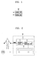
- FIG. 1 is a view illustrating a configuration of a circuit for driving a cooker disclosed in the present disclosure.
- FIG. 2 is a view illustrating a configuration according to an embodiment of a circuit for driving a cooker disclosed in the present disclosure.
- a circuit 100 for driving a cooker includes a sensing unit 10 sensing a movement of a user who uses a cooker and a contact unit 20 switching a power circuit to which power is supplied from the outside and performing a closing operation on the basis of a sensing result from the sensing unit 10 to supply power to the cooker.
- the driving circuit 100 may refer to a circuit for supplying power to drive the cooker.
- the driving circuit 100 may be a circuit included in the cooker.
- the driving circuit 100 may be a circuit connected to the outside of the cooker and driving the cooker.
- the driving circuit 100 may be configured in the form of a module.
- the sensing unit 10 may sense a movement of the user of the cooker, and the contact unit 20 may performing a closing operation on the basis of the sensing result from the sensing unit 10 so that the power circuit, to which power is supplied from the outside, is closed to allow power to be supplied to the cooker.
- the driving circuit 100 may be connected to the power circuit to which power is supplied from the outside, to allow power to be supplied to the cooker.
- the sensing unit 10 may be positioned on a front portion of the cooker.
- the sensing unit 10 may sense a movement of the user on a front portion of the cooker.
- the sensing unit 10 may include an infrared sensor 11 infrared-sensing a movement of the user.
- the infrared sensor 11 may be configured to identify movement of the user by sensing infrared light.
- the infrared sensor 11 may refer to a passive infrared ray sensor sensing a change in infrared rays according to a movement of a human body and converting the sensed change into an amount of electricity.
- the sensing unit 10 may sense a movement of the user on the front portion of the cooker through the infrared sensor 11.
- the sensing unit 10 may further include a signal generating unit 12 generating an operation signal regarding controlling of a closing operation of the contact unit 20.
- the signal generating unit 12 may be configured to generate the operation signal based on the infrared sensor identifying movement of the user.
- the sensing unit 10 may generate the operation signal according to a sensing result from the infrared sensor 11 through the signal generating unit 12.
- the signal generating unit 12 may generate the operation signal in a case in which a movement of the user of the cooker is sensed for a predetermined period of time.
- the predetermined period of time may be a period of time during which the user is supposed to use the cooker.
- the predetermined period of time may be a period of time of 3 seconds or greater.
- the sensing unit 10 may sense a movement of the user on the front portion of the cooker for a predetermined period of time through the infrared sensor 11, and in some implementations, in which a movement of the user is sensed for the predetermined period of time, since the user is supposed to use the cooker, the sensing unit 10 may generate the operation signal according to the sensing result for the predetermined period of time through the signal generating unit 12.
- the sensing unit 10 may generate the operation signal and transmit the generated operation signal to the contact unit 20.
- the contact unit 20 may be configured to disconnect power that is received.
- the contact unit 20 may be configured to provide to the cooker, power that is received from the power circuit in response to the operation signal from the sensing unit.
- the contact unit 20 may receive the operation signal from the sensing unit 10.
- the contact unit 20 may switch the power circuit supply power from the outside to the cooker, so that power may be supplied to the cooker or power supply to the cooker may be cut off.
- the contact unit 20 may be an physical contact (a contact or switch) which is open at normal times and which is closed at the time of operation, or the contact unit 20 may comprise a switch that is configured to be open except during operation of the cooker and is configured to close in response to the operation signal.
- the contact unit 20 is open at normal times not to supply power to the cooker, and is closed at the time of operation to supply power to the cooker.
- the contact unit 20 may perform a closing operation on the basis of the operation signal.
- the contact unit 20 may perform a closing operation to supply power to the cooker.
- FIGS. 3 and 4 illustrate example systems for driving a cooker.
- a system 400 for driving a cooker includes a driving unit 100 including a sensing unit 10 sensing a movement of a user and a contact unit 20 switching a power circuit to which power is supplied from the outside, and performing a closing operation on the basis of a sensing result from the sensing unit 10 to supply power to the cooker, and a control unit 200 driven by power supplied from the power circuit to control an operation of the contact unit 20.
- the driving system 400 may refer to a circuit system for driving the cooker.
- the driving system 400 may refer to a system including a plurality of circuits included in the cooker.
- the driving system 400 may be a system including the driving circuit 100 described above.
- the driving unit 100 may allow power for driving the cooker to be supplied to the cooker, and the control unit 200 may be driven by power supplied through the driving unit 100 to control an operation of the contact unit 20 .
- the driving unit 100 may be the driving circuit 100 described above.
- the driving unit 100 may be a circuit included in the cooker.
- the driving unit 100 may be a circuit connected to the outside of the cooker to enable the cooker to be driven.
- the driving unit 100 may be configured in the form of a module.
- the control unit 200 may be a circuit included in the cooker.
- the control unit 200 may be a micro controller unit (MCU) controlling driving and an operation of the cooker.
- MCU micro controller unit
- the sensing unit 10 may sense a movement of the user of the cooker, and the contact unit 20 may performing a closing operation on the basis of the sensing result from the sensing unit 10 so that the power circuit, to which power is supplied from the outside, is closed to allow power to be supplied to the cooker.
- the driving circuit 100 may be connected to the power circuit to which power is supplied from the outside, to allow power to be supplied to the cooker including the control unit 200.
- the sensing unit 10 may be positioned on a front portion of the cooker.
- the sensing unit 10 may infrared-sense a movement of the user of the cooker and generate an operation signal regarding controlling of a closing operation of the contact unit 20 according to the sensing result.
- the sensing unit 10 may be configured to output the operation signal based on sensed movement of a user.
- the sensing unit 10 may include an infrared sensor 11 infrared-sensing a movement of the user.
- the infrared sensor 11 may refer to a passive infrared ray sensor sensing a change in infrared rays according to a movement of a human body and converting the sensed change into an amount of electricity.
- the sensing unit 10 may sense a movement of the user on the front portion of the cooker through the infrared sensor 11.
- the sensing unit 10 may further include a signal generating unit 12 generating an operation signal regarding controlling of a closing operation of the contact unit 20.
- the sensing unit 10 may generate the operation signal though the signal generating unit 12.
- the predetermined period of time may be a period of time during which the user is supposed to use the cooker.
- the predetermined period of time may be a period of time of 3 seconds or greater.
- the sensing unit 10 senses a movement of the user on the front portion of the cooker for a predetermined period of time through the infrared sensor 11, and in some implementations, in which a movement of the user is sensed for the predetermined period of time, since the user is supposed to use the cooker, the sensing unit 10 may generate the operation signal according to the sensing result for the predetermined period of time through the signal generating unit 12.
- the sensing unit 10 may generate the operation signal and transmit the generated operation signal to the contact unit 20.
- the contact unit 20 may receive the operation signal from the sensing unit 10.
- the contact unit 20 may switch the power circuit supplying power from the outside to the cooker, so that power may be supplied to the cooker or power supply to the cooker may be cut off.
- the contact unit 20 may supply power to the cooker to enable the control unit 200 to be driven.
- the contact unit 20 may be an physical contact (a contact or switch) which is open at normal times and which is closed at the time of operation.
- the contact unit 20 is open at normal times not to supply power to the cooker, and is closed at the time of operation to supply power to the cooker.
- the contact unit 20 may perform a closing operation on the basis of the operation signal and may maintain the closing operation on the basis of a signal generated by the control unit 200.
- the contact unit 10 may receive the operation signal, which has been generated on the basis of a result of sensing a movement of the user on the front portion of the cooker for a predetermined period of time, from the sensing unit 10, perform a closing operation on the basis of the operation signal to supply power to the cooker, and maintain the closing operation under the control of the control unit 200 which is driven upon receiving power.
- the contact unit 20 may maintain the closing operation on the basis of the signal generated by the control unit 200 to maintain power supply to the cooker.
- the contact unit 20 may be returned to an open state when there is no signal generated by the sensing unit 10 or the control unit 200.
- power supply to the cooker is not required so a signal is not generated by the sensing unit 10 or the control unit 200, the contact unit 20 may be returned from the closing operation to a previous state (e.g., an open state) so that power may not be supplied.
- a previous state e.g., an open state
- the control unit 200 may be driven by power supplied through the power circuit.
- the control unit 200 may be configured to, based on the control unit 200 controlling the operation of the cooker, maintain the contact unit 20 in a closed position.
- control unit 200 After the control unit 200 is driven by power supplied through the power circuit, the control unit 200 may generate a sustain signal for controlling maintaining the closing operation of the contact unit 20.
- control unit 200 after the control unit 200 is driven by power supplied through the power circuit, the control unit 200 generates the sustain signal to maintain power supply through the power circuit to thus control the contact unit 20.
- the control unit 200 controls the contact unit 20 to maintain the closing operation, whereby power supplied through the power circuit may be maintained to maintain the driving.
- control unit 200 may control an operation of the cooker.
- control unit 200 since the control unit 200 is driven upon receiving power through the power circuit, the control unit 200 may control driving and operation of the cooker.
- the control unit 200 may control an operation of the cooker such that a cooking function of the cooker is executed.
- control unit may control an operation of the cooker to perform a cooking function corresponding to a user input.
- control unit 200 may control the contact unit 20 to maintain the closing operation of the contact unit 20.
- control unit 200 may control the contact unit 20 to maintain the closing operation of the contact unit 20 such that power supply to the cooker is maintained.
- FIGS. 5 and 6 illustrate of example cookers.
- FIG. 7 illustrates an example circuit of a cooker.
- the cooker 500 includes a driving unit 100 including a sensing unit 10 sensing a movement of a user who uses a cooker and a contact unit 20 switching a power circuit to which power is supplied from the outside and performing a closing operation on the basis of a sensing result from the sensing unit 10 to receive power, a cooking unit 300 performing a cooking operation of the cooker 500, and a control unit 200 driven by power supplied through the power circuit to control operations of the contact unit 20 and the cooking unit 300.
- a driving unit 100 including a sensing unit 10 sensing a movement of a user who uses a cooker and a contact unit 20 switching a power circuit to which power is supplied from the outside and performing a closing operation on the basis of a sensing result from the sensing unit 10 to receive power, a cooking unit 300 performing a cooking operation of the cooker 500, and a control unit 200 driven by power supplied through the power circuit to control operations of the contact unit 20 and the cooking unit 300.
- the cooker 500 may refer to a device for cooking food using an electric energy, such as a microwave oven, an oven, or an induction heating (IH) cooker.
- an electric energy such as a microwave oven, an oven, or an induction heating (IH) cooker.
- the cooker 500 may include a plurality of circuits to perform a cooking function.
- the cooker 500 may include the driving circuit 100 or the driving system 400 described above.
- the driving unit 100 receives power for driving the cooker 500
- the cooking unit 300 is driven by power received through the driving unit 100 to perform a cooking operation such that a cooking function of the cooker 500 may be performed
- the control unit 200 may be driven by power received through the driving unit 100 to control operations of the contact unit 20 and the cooking unit 300.
- the driving unit 100 may be the driving circuit 100 described above.
- the control unit 200 may be a micro controller unit (MCU) controlling driving and an operation of the cooker 500.
- MCU micro controller unit
- the configuration including the driving unit 100 and the control unit 200 may be the driving system 400 described above.
- the cooking unit 300 may be driven by the driving system 400 to perform a cooking operation of the cooker 500.
- the cooker 500 includes the driving system 400 performing driving and the cooking unit 300 performing cooking, and the cooking unit 300 is driven through the driving system 400 to perform cooking.
- the sensing unit 10 may sense a movement of the user of the cooker 500, and the contact unit 20 may performing a closing operation on the basis of the sensing result from the sensing unit 10 so that the power circuit, to which power is supplied from the outside, is closed to receive power.
- the driving circuit 100 may be connected to the power circuit to which power is supplied from the outside, to allow power to be supplied to the cooker including the control unit 200.
- the sensing unit 10 may be positioned on a front portion of the cooker.
- the sensing unit 10 may infrared-sense a movement of the user of the cooker and generate an operation signal regarding controlling of a closing operation of the contact unit 20 according to the sensing result.
- the sensing unit 10 may include an infrared sensor 11 infrared-sensing a movement of the user.
- the infrared sensor 11 may refer to a passive infrared ray sensor sensing a change in infrared rays according to a movement of a human body and converting the sensed change into an amount of electricity.
- the sensing unit 10 may sense a movement of the user on the front portion of the cooker through the infrared sensor 11.
- the sensing unit 10 may further include a signal generating unit 12 generating an operation signal regarding controlling of a closing operation of the contact unit 20.
- the sensing unit 10 may generate the operation signal though the signal generating unit 12.
- the predetermined period of time may be a period of time during which the user is supposed to use the cooker.
- the predetermined period of time may be a period of time of 3 seconds or greater.
- the sensing unit 10 senses a movement of the user on the front portion of the cooker for a predetermined period of time through the infrared sensor 11, and in some implementations, in which a movement of the user is sensed for the predetermined period of time, since the user is supposed to use the cooker, the sensing unit 10 may generate the operation signal according to the sensing result for the predetermined period of time through the signal generating unit 12.
- the sensing unit 10 may generate the operation signal and transmit the generated operation signal to the contact unit 20.
- the contact unit 20 may receive the operation signal from the sensing unit 10.
- the contact unit 20 may switch the power circuit supplying power from the outside to the cooker 500, so that power may be supplied or cut off.
- the contact unit 20 may allow power to be supplied to enable the cooking unit 300 and the control unit 200 to be driven.
- the contact unit 20 may be an physical contact (a contact or switch) which is open at normal times and which is closed at the time of operation.
- the contact unit 200 is open at normal times to prevent power from being supplied, and is closed at the time of operation to allow power to be supplied.
- the contact unit 20 may receive the generated operation signal from the sensing unit 10, perform a closing operation on the basis of the operation signal, and maintain the closing operation on the basis of a signal generated by the control unit 200.
- the contact unit 10 may receive the operation signal, which has been generated on the basis of a result of sensing a movement of the user on the front portion of the cooker 500 for a predetermined period of time, from the sensing unit 10 and perform a closing operation to allow power to be supplied, and when the control unit 200 is driven upon receiving power, the contact unit 10 may maintain the closing operation under the control of the control unit 200.
- the contact unit 20 may maintain the closing operation on the basis of a signal generated by the control unit 200, such that power supply to the cooking unit 300 and the control unit 200 is maintained.
- the contact unit 20 may be returned to an open state when there is no signal generated by the sensing unit 10 or the control unit 200.
- power supply is not required so a signal is not generated by the sensing unit 10 or the control unit 200, the contact unit 20 may be returned from the closing operation to the open state so that power may not be supplied.
- the cooking unit 300 may be driven by power supplied through the power circuit.
- an operation of the cooking unit 300 may be controlled by the control unit 200.
- the cooking unit 300 may perform a cooking operation on food as a cooking target.
- the cooking unit 300 may be controlled by the control unit to perform a cooking function to heat food.
- the control unit 200 may control the cooking unit 300 to heat a cooking container positioned at an upper portion of the cooker 500 to 100°C.
- IH induction heating
- the control unit 200 may be driven by power supplied through the power circuit.
- control unit 200 After the control unit 200 is driven by power supplied through the power circuit, the control unit 200 may generate a sustain signal for controlling maintaining the closing operation of the contact unit 20.
- control unit 200 after the control unit 200 is driven by power supplied through the power circuit, the control unit 200 generates the sustain signal to maintain power supply through the power circuit to thus control the contact unit 20.
- control unit 200 may control the contact unit 20 to maintain the closing operation, whereby power supplied through the power circuit may be maintained to maintain the driving.
- control unit 200 may control an operation of the cooking unit 300.
- control unit 200 since the control unit 200 is driven upon receiving power through the power circuit, the control unit 200 may control driving and operation of the cooker.
- the control unit 200 may control an operation of the cooker such that a cooking function of the cooker is executed.
- control unit may control an operation of the cooker to perform a cooking function corresponding to a user input.
- control unit 200 may control the contact unit 20 to maintain the closing operation of the contact unit 20.
- control unit 200 may control the contact unit 20 to maintain the closing operation of the contact unit 20 such that power supply to the cooker is maintained.
- a circuit configuration of the cooker 500 described above may have a form as illustrated in FIG. 7 .
- the contact unit 20 of the driving unit may perform a closing operation on the basis of signals generated by the sensing unit 10 of the driving unit 100 and the control unit 200.
- the sensing unit 10, the control unit 200, and the contact unit 20 may be configured as an OR gate in which an output is performed when there are one or more inputs.
- the sensing unit 10 and the control unit 200 are connected to an input of the OR gate, and an output of the OR gate is connected to the contact unit 20, and accordingly, when the sensing unit 10 or the control unit 200 generates a signal, the contact unit 20 may perform a closing operation.
- the sensing unit 10 senses a movement of the user on a front portion of the cooker 500
- the sensing unit 10 generates the operation signal
- the operation signal is transmitted to the contact unit 20
- the contact unit 20 performs a closing operation such that the power circuit to which power is supplied from the outside is closed. Since the power circuit is closed, power is supplied to the cooking unit 300 and the control unit 200, and thus, the control unit 200 may be driven.
- control unit 200 After the control unit 200 is driven, the control unit 200 generates the sustain signal to maintain the closing operation of the contact unit 20 in order to continuously receive power, and when the sustain signal is transmitted to the contact unit 20, the contact unit 20 maintains the closing operation, and thus, power supply to the control unit 200 is maintained, whereby driving of the control unit 200 may be maintained.
- control unit 200 After driving of the control unit 200 is maintained, the control unit 200 controls an operation of the cooking unit 300 to perform a cooking function of the cooker 500, and in order to continuously receive power while the cooking unit 300 is being operated, the control unit 200 may control the contact unit 200 to maintain the closing operation.
- FIGS. 8-11 illustrate example methods for driving a cooker.
- a method for driving a cooker (hereinafter, referred to as a "driving method") is a method for driving the cooker 500 including the sensing unit 10 sensing a movement of a user of the cooker 500, the cooking unit 300 performing a cooking operation of the cooker 500, and the control unit 200 driven by power supplied through the power circuit to control operations of the contact unit 20 and the cooking unit 300.
- the driving method may be the method for driving the cooker 500 described above.
- the driving method includes: step (S10) in which the sensing unit 10 senses a movement of a user of the cooker 500, step (S20) in which the contact unit 20 performs a closing operation on the basis of the sensing result, step (S30) in which the cooking unit 300 and the control unit 200 are driven with power supplied through the power circuit, step (S40) in which the control unit 200 controls an operation of the contact unit 20 to maintain the closing operation, and step (S50) in which driving of the cooking unit 300 and the control unit 200 is maintained by maintaining power supplied through the power circuit.
- Step (S10) of sensing a movement of a user of the cooker 500 may be performed by the sensing unit 10.
- step (S10) of sensing a movement of the user of the cooker 500 a movement of the user on the front portion of the cooker 500 may be sensed through the sensing unit 10 positioned on the front portion of the cooker 500.
- step (S10) of sensing a movement of the user of the cooker 500 may include step (S11) of infrared-sensing a movement of the user of the cooker 500, step (S12) of generating an operation signal regarding controlling of a closing operation of the contact unit 20 according to the sensing result, and step (S13) of transmitting the operation signal to the contact unit 20.
- step (S11) of infrared-sensing a movement of the user of the cooker 500 the sensing unit 10 may infrared-sense a movement of the user on the front portion of the cooker 500.
- step (S12) of generating an operation signal the sensing unit 10 may generate an operation signal regarding controlling of a closing operation of the contact unit 20 according to the sensing result.
- step (S12) when a movement of the user of the cooker 500 is sensed for a predetermined period of time, the sensing unit 10 may generate the operation signal.
- the predetermined period of time may be a period of time during which the user is supposed to use the cooker 500.
- the predetermined period of time may be a period of time of three seconds or more.
- step (S13) of transmitting the operation signal to the contact unit 20 the sensing unit 10 may transmit the operation signal to the contact unit 20.
- Step (S20) of performing a closing operation on the basis of the sensing result may be performed through the contact unit 20.
- step (S20) of performing a closing operation on the basis of the sensing result the contact unit 20 performs a closing operation on the basis of a signal transmitted from the sensing unit 10 to close the power circuit which receives power from the outside.
- step (S20) of performing a closing operation on the basis of the sensing result the contact unit 20 switches the power circuit which receives power from the outside to supply power to the cooking unit 300 and the control unit 200 or to cut off power supply thereto.
- Step (S30) of driving the cooking unit 300 and the control unit 200 may be performed through the cooking unit 300 and the control unit 200 upon receiving power as the contact unit 20 performs a closing operation.
- step (S30) of driving the cooking unit 300 and the control unit 200 the cooking unit 300 and the control unit 200 may be provided with power so as to be driven.
- Step (S40) of controlling an operation of the contact unit 20 may be performed through the control unit 200.
- step (S40) of controlling an operation of the contact unit 20 may include step (S41) of generating a sustain signal regarding controlling of maintaining a closing operation of the contact unit 20 and step (S42) of transmitting the sustain signal to the contact unit 20.
- step (S41) of generating a sustain signal after the control unit 200 is driven by power supplied through the power circuit, the control unit 200 may generate a sustain signal regarding controlling of maintaining the closing operation of the contact unit 20.
- step (S42) of transmitting the sustain signal to the contact unit 20 the control unit 20 may transmit the sustain signal to the contact unit 20.
- step (S40) of controlling the operation of the contact unit 20 after the controller 200 is driven with power supplied through the power circuit, the control unit 200 may generate the sustain signal to maintain power supply through the power circuit to thus control the contact unit 20.
- Step (S50) of maintaining driving of the cooking unit 300 and the control unit 200 may be performed through the control unit 200 maintained in driving as power supplied through the power circuit is maintained.
- step (S50) of maintaining driving of the cooking unit 300 and the control unit 200 the contact unit 20 maintains the closing operation on the basis of a signal generated by the control unit 200 such that power supply to the cooking unit 300 and the control unit 200 is maintained.
- Step (S50) of maintaining driving of the cooking unit 300 and the control unit 200 may include step (S51) in which the control unit 200 controls an operation of the cooking unit 300 and step (S52) in which, while the control unit 200 controls the operation of the cooking unit 300, the control unit 200 controls the contact unit 20 to maintain the closing operation.
- step (S51) of controlling an operation of the cooking unit 300 in a state in which driving of the control unit 200 is maintained by maintaining power supplied through the power circuit, an operation of the cooking unit 300 may be controlled.
- control unit 200 may control an operation of the cooking unit 300 such that a cooking function of the cooker 500 is performed.
- Step (S52) of controlling the contact unit 20 to maintain the closing operation while the control unit 200 controls an operation of the cooking unit 300, the contact unit 20 may be controlled to maintain the closing operation.
- step (S50) of maintaining driving of the cooking unit 300 and the control unit 200 the control unit 200 is driven upon receiving power through the power circuit to control driving and an operation of the cooker 500.
- the circuit for driving a cooker, the system for driving a cooker, the cooker, and the method for driving a cooker disclosed in the present disclosure may be applied to and implemented in power circuits and driving circuits of home appliances and power circuits and driving circuits of industrial electric equipment.
- the circuit for driving a cooker, the system for driving a cooker, the cooker, and the method for driving a cooker disclosed in the present disclosure may be applied to and implemented in power supply devices, power supply systems, driving devices, and driving system of home appliances and industrial electric equipment.
- the circuit for driving a cooker, the system for driving a cooker, the cooker, and the method for driving a cooker disclosed in the present disclosure may be applied to and implemented power supply methods and driving methods of home appliances and industrial electric equipment.
- the circuit for driving a cooker, the system for driving a cooker, the cooker, and the method for driving a cooker disclosed in the present disclosure may be applied to and implemented in induction heating cookers using electric energy.
- the circuit for driving a cooker the system for driving a cooker, the cooker, and the method for driving a cooker disclosed in the present disclosure, since power is supplied according to a result of sensing a movement of a user, consumption of standby power may be reduced.
- the circuit for driving a cooker the system for driving a cooker, the cooker, and the method for driving a cooker disclosed in the present disclosure, since power is supplied according to a result of sensing a movement of a user, insulation of cooker and electric leakage may be reduced.
- the circuit for driving a cooker the system for driving a cooker, the cooker, and the method for driving a cooker disclosed in the present disclosure, since insulation of cooker and electric leakage are reduced, usage stability of a cooker may be increased.
- the circuit for driving a cooker the system for driving a cooker, the cooker, and the method for driving a cooker disclosed in the present disclosure, since power is supplied according to a result of sensing a movement of the user, power supply and driving of a cooker may be automatically performed.
- the circuit for driving a cooker the system for driving a cooker, the cooker, and the method for driving a cooker disclosed in the present disclosure, since power supply and driving of a cooker are automatically performed, usage convenience of a cooker may be increased.
Landscapes
- Engineering & Computer Science (AREA)
- Chemical & Material Sciences (AREA)
- Combustion & Propulsion (AREA)
- Mechanical Engineering (AREA)
- General Engineering & Computer Science (AREA)
- Physics & Mathematics (AREA)
- Electromagnetism (AREA)
- Food Science & Technology (AREA)
- Human Computer Interaction (AREA)
- Electric Stoves And Ranges (AREA)
- Induction Heating Cooking Devices (AREA)
Applications Claiming Priority (1)
| Application Number | Priority Date | Filing Date | Title |
|---|---|---|---|
| KR1020140191051A KR101635048B1 (ko) | 2014-12-26 | 2014-12-26 | 조리기기의 구동회로, 조리기기의 구동시스템, 조리기기 및 조리기기의 구동방법 |
Publications (2)
| Publication Number | Publication Date |
|---|---|
| EP3038431A1 true EP3038431A1 (fr) | 2016-06-29 |
| EP3038431B1 EP3038431B1 (fr) | 2020-04-22 |
Family
ID=54979582
Family Applications (1)
| Application Number | Title | Priority Date | Filing Date |
|---|---|---|---|
| EP15202268.7A Active EP3038431B1 (fr) | 2014-12-26 | 2015-12-23 | Circuit d'attaque pour cuiseur, système d'entraînement de cuisinière, cuisinière et procédé de pilotage de cuisinière |
Country Status (4)
| Country | Link |
|---|---|
| US (1) | US10925126B2 (fr) |
| EP (1) | EP3038431B1 (fr) |
| KR (1) | KR101635048B1 (fr) |
| CN (1) | CN105725818A (fr) |
Cited By (1)
| Publication number | Priority date | Publication date | Assignee | Title |
|---|---|---|---|---|
| EP3951268A1 (fr) * | 2020-08-06 | 2022-02-09 | E.G.O. Elektro-Gerätebau GmbH | Plaque de cuisson et procédé de fonctionnement d'une plaque de cuisson |
Families Citing this family (2)
| Publication number | Priority date | Publication date | Assignee | Title |
|---|---|---|---|---|
| WO2017153360A1 (fr) * | 2016-03-09 | 2017-09-14 | Koninklijke Philips N.V. | Cuiseur à friture à air chaud et procédé de nettoyage de cuiseur à friture à air chaud |
| CN110045639A (zh) * | 2018-01-17 | 2019-07-23 | 佛山市顺德区美的电热电器制造有限公司 | 锅具及其运行系统、运行系统唤醒方法 |
Citations (5)
| Publication number | Priority date | Publication date | Assignee | Title |
|---|---|---|---|---|
| DE10130198A1 (de) * | 2001-06-22 | 2003-01-02 | Diehl Ako Stiftung Gmbh & Co | Herdschaltuhr |
| EP1276351A2 (fr) * | 2001-07-11 | 2003-01-15 | Samsung Electronics Co., Ltd. | Four à micro-ondes possédant un détecteur de proximité |
| US20050109333A1 (en) * | 2003-11-21 | 2005-05-26 | Thomas Lowell R. | Safety device for regulating electrical power to a cooking appliance |
| WO2007139521A2 (fr) * | 2006-05-30 | 2007-12-06 | Bc2222 D.O.O. | Dispositif de protection pour des appareils ménagers thermiques autonomes |
| WO2011133119A2 (fr) * | 2010-04-22 | 2011-10-27 | National Science And Technology Development Agency | Système doté d'un mode de veille à puissance nulle et permettant de commander un appareil électrique |
Family Cites Families (6)
| Publication number | Priority date | Publication date | Assignee | Title |
|---|---|---|---|---|
| US4820891A (en) * | 1986-11-29 | 1989-04-11 | Kabushiki Kaisha Toshiba | Induction heated cooking apparatus |
| JPH06300280A (ja) * | 1993-04-13 | 1994-10-28 | Toshiba Corp | 加熱調理器 |
| JPH10300100A (ja) * | 1997-04-24 | 1998-11-13 | Sanyo Electric Co Ltd | 加熱調理器 |
| US6294994B1 (en) * | 1999-03-15 | 2001-09-25 | Wendy Hoellerich | Appliance attendance monitoring apparatus |
| JP2004293953A (ja) * | 2003-03-27 | 2004-10-21 | Tokyo Gas Co Ltd | 人感センサー付きコンロ |
| CA2567691A1 (fr) * | 2006-11-09 | 2008-05-09 | Georges Dufour | Systeme sans fil de coupure de l'alimentation d'un detecteur de fumee |
-
2014
- 2014-12-26 KR KR1020140191051A patent/KR101635048B1/ko active Active
-
2015
- 2015-12-23 EP EP15202268.7A patent/EP3038431B1/fr active Active
- 2015-12-25 CN CN201510993914.7A patent/CN105725818A/zh active Pending
- 2015-12-28 US US14/979,761 patent/US10925126B2/en active Active
Patent Citations (5)
| Publication number | Priority date | Publication date | Assignee | Title |
|---|---|---|---|---|
| DE10130198A1 (de) * | 2001-06-22 | 2003-01-02 | Diehl Ako Stiftung Gmbh & Co | Herdschaltuhr |
| EP1276351A2 (fr) * | 2001-07-11 | 2003-01-15 | Samsung Electronics Co., Ltd. | Four à micro-ondes possédant un détecteur de proximité |
| US20050109333A1 (en) * | 2003-11-21 | 2005-05-26 | Thomas Lowell R. | Safety device for regulating electrical power to a cooking appliance |
| WO2007139521A2 (fr) * | 2006-05-30 | 2007-12-06 | Bc2222 D.O.O. | Dispositif de protection pour des appareils ménagers thermiques autonomes |
| WO2011133119A2 (fr) * | 2010-04-22 | 2011-10-27 | National Science And Technology Development Agency | Système doté d'un mode de veille à puissance nulle et permettant de commander un appareil électrique |
Cited By (1)
| Publication number | Priority date | Publication date | Assignee | Title |
|---|---|---|---|---|
| EP3951268A1 (fr) * | 2020-08-06 | 2022-02-09 | E.G.O. Elektro-Gerätebau GmbH | Plaque de cuisson et procédé de fonctionnement d'une plaque de cuisson |
Also Published As
| Publication number | Publication date |
|---|---|
| US20160183711A1 (en) | 2016-06-30 |
| KR101635048B1 (ko) | 2016-06-30 |
| US10925126B2 (en) | 2021-02-16 |
| CN105725818A (zh) | 2016-07-06 |
| EP3038431B1 (fr) | 2020-04-22 |
Similar Documents
| Publication | Publication Date | Title |
|---|---|---|
| KR102031875B1 (ko) | 전자 유도 가열 조리기 및 이의 구동 방법 | |
| WO2009037783A1 (fr) | Appareil de refroidissement pour appareil de cuisson à chauffage par induction électromagnétique | |
| EP3038431A1 (fr) | Circuit d'attaque pour cuiseur, système d'entraînement de cuisinière, cuisinière et procédé de pilotage de cuisinière | |
| EP2934064B1 (fr) | Gestion de puissance pour appareils domestiques | |
| CN112969891A (zh) | 电炉灶和电炉灶的控制方法 | |
| EP2302605A1 (fr) | Assemblage et procédé pour la surveillance d'un ensemble d'appareils ménagers | |
| CN106123054A (zh) | 一种电加热炉具 | |
| JP2013000203A (ja) | 誘導加熱式炊飯器 | |
| JP5262971B2 (ja) | 加熱調理器 | |
| US20110266889A1 (en) | Cost effective energy saving device | |
| CN208186439U (zh) | 一种控制装置及集成灶 | |
| KR20110058143A (ko) | 충전 밧데리를 갖는 전자레인지 | |
| KR20090102013A (ko) | 조리기기 및 그 제어방법 | |
| EP3685711B1 (fr) | Appareil de cuisson du type divisé et procédé de commande correspondant | |
| CN109730521B (zh) | 一种用于厨用电器无线供电的烹饪灶具装置 | |
| KR102919189B1 (ko) | 터치 방식의 인덕션 제어 시스템 | |
| US12619294B2 (en) | System and method for controlling an appliance with a loss of power | |
| US20250335014A1 (en) | System and method for recovering an appliance mode after loss of power | |
| KR20000043279A (ko) | 전자렌지의 절전방법 | |
| KR102367297B1 (ko) | 대기 전력 차단 기능을 지닌 전기 기기 | |
| CN205072651U (zh) | 一种节能型电饭锅 | |
| CN1888568B (zh) | 微波炉的安全装置 | |
| KR100674571B1 (ko) | 전자레인지의 안전장치 | |
| CN205987434U (zh) | 防起火保护电路及电磁炉 | |
| KR100606745B1 (ko) | 조리기기의 릴레이 구동 안전회로 |
Legal Events
| Date | Code | Title | Description |
|---|---|---|---|
| PUAI | Public reference made under article 153(3) epc to a published international application that has entered the european phase |
Free format text: ORIGINAL CODE: 0009012 |
|
| AK | Designated contracting states |
Kind code of ref document: A1 Designated state(s): AL AT BE BG CH CY CZ DE DK EE ES FI FR GB GR HR HU IE IS IT LI LT LU LV MC MK MT NL NO PL PT RO RS SE SI SK SM TR |
|
| AX | Request for extension of the european patent |
Extension state: BA ME |
|
| 17P | Request for examination filed |
Effective date: 20160727 |
|
| RBV | Designated contracting states (corrected) |
Designated state(s): AL AT BE BG CH CY CZ DE DK EE ES FI FR GB GR HR HU IE IS IT LI LT LU LV MC MK MT NL NO PL PT RO RS SE SI SK SM TR |
|
| STAA | Information on the status of an ep patent application or granted ep patent |
Free format text: STATUS: EXAMINATION IS IN PROGRESS |
|
| 17Q | First examination report despatched |
Effective date: 20170412 |
|
| GRAP | Despatch of communication of intention to grant a patent |
Free format text: ORIGINAL CODE: EPIDOSNIGR1 |
|
| STAA | Information on the status of an ep patent application or granted ep patent |
Free format text: STATUS: GRANT OF PATENT IS INTENDED |
|
| INTG | Intention to grant announced |
Effective date: 20191129 |
|
| RIN1 | Information on inventor provided before grant (corrected) |
Inventor name: KIM, HONGGYU |
|
| GRAS | Grant fee paid |
Free format text: ORIGINAL CODE: EPIDOSNIGR3 |
|
| GRAA | (expected) grant |
Free format text: ORIGINAL CODE: 0009210 |
|
| STAA | Information on the status of an ep patent application or granted ep patent |
Free format text: STATUS: THE PATENT HAS BEEN GRANTED |
|
| AK | Designated contracting states |
Kind code of ref document: B1 Designated state(s): AL AT BE BG CH CY CZ DE DK EE ES FI FR GB GR HR HU IE IS IT LI LT LU LV MC MK MT NL NO PL PT RO RS SE SI SK SM TR |
|
| REG | Reference to a national code |
Ref country code: CH Ref legal event code: EP |
|
| REG | Reference to a national code |
Ref country code: DE Ref legal event code: R096 Ref document number: 602015051067 Country of ref document: DE |
|
| REG | Reference to a national code |
Ref country code: IE Ref legal event code: FG4D |
|
| REG | Reference to a national code |
Ref country code: AT Ref legal event code: REF Ref document number: 1261890 Country of ref document: AT Kind code of ref document: T Effective date: 20200515 |
|
| REG | Reference to a national code |
Ref country code: LT Ref legal event code: MG4D |
|
| REG | Reference to a national code |
Ref country code: NL Ref legal event code: MP Effective date: 20200422 |
|
| PG25 | Lapsed in a contracting state [announced via postgrant information from national office to epo] |
Ref country code: NO Free format text: LAPSE BECAUSE OF FAILURE TO SUBMIT A TRANSLATION OF THE DESCRIPTION OR TO PAY THE FEE WITHIN THE PRESCRIBED TIME-LIMIT Effective date: 20200722 Ref country code: SE Free format text: LAPSE BECAUSE OF FAILURE TO SUBMIT A TRANSLATION OF THE DESCRIPTION OR TO PAY THE FEE WITHIN THE PRESCRIBED TIME-LIMIT Effective date: 20200422 Ref country code: IS Free format text: LAPSE BECAUSE OF FAILURE TO SUBMIT A TRANSLATION OF THE DESCRIPTION OR TO PAY THE FEE WITHIN THE PRESCRIBED TIME-LIMIT Effective date: 20200822 Ref country code: FI Free format text: LAPSE BECAUSE OF FAILURE TO SUBMIT A TRANSLATION OF THE DESCRIPTION OR TO PAY THE FEE WITHIN THE PRESCRIBED TIME-LIMIT Effective date: 20200422 Ref country code: LT Free format text: LAPSE BECAUSE OF FAILURE TO SUBMIT A TRANSLATION OF THE DESCRIPTION OR TO PAY THE FEE WITHIN THE PRESCRIBED TIME-LIMIT Effective date: 20200422 Ref country code: GR Free format text: LAPSE BECAUSE OF FAILURE TO SUBMIT A TRANSLATION OF THE DESCRIPTION OR TO PAY THE FEE WITHIN THE PRESCRIBED TIME-LIMIT Effective date: 20200723 Ref country code: PT Free format text: LAPSE BECAUSE OF FAILURE TO SUBMIT A TRANSLATION OF THE DESCRIPTION OR TO PAY THE FEE WITHIN THE PRESCRIBED TIME-LIMIT Effective date: 20200824 Ref country code: NL Free format text: LAPSE BECAUSE OF FAILURE TO SUBMIT A TRANSLATION OF THE DESCRIPTION OR TO PAY THE FEE WITHIN THE PRESCRIBED TIME-LIMIT Effective date: 20200422 |
|
| REG | Reference to a national code |
Ref country code: AT Ref legal event code: MK05 Ref document number: 1261890 Country of ref document: AT Kind code of ref document: T Effective date: 20200422 |
|
| PG25 | Lapsed in a contracting state [announced via postgrant information from national office to epo] |
Ref country code: LV Free format text: LAPSE BECAUSE OF FAILURE TO SUBMIT A TRANSLATION OF THE DESCRIPTION OR TO PAY THE FEE WITHIN THE PRESCRIBED TIME-LIMIT Effective date: 20200422 Ref country code: RS Free format text: LAPSE BECAUSE OF FAILURE TO SUBMIT A TRANSLATION OF THE DESCRIPTION OR TO PAY THE FEE WITHIN THE PRESCRIBED TIME-LIMIT Effective date: 20200422 Ref country code: BG Free format text: LAPSE BECAUSE OF FAILURE TO SUBMIT A TRANSLATION OF THE DESCRIPTION OR TO PAY THE FEE WITHIN THE PRESCRIBED TIME-LIMIT Effective date: 20200722 Ref country code: HR Free format text: LAPSE BECAUSE OF FAILURE TO SUBMIT A TRANSLATION OF THE DESCRIPTION OR TO PAY THE FEE WITHIN THE PRESCRIBED TIME-LIMIT Effective date: 20200422 |
|
| PG25 | Lapsed in a contracting state [announced via postgrant information from national office to epo] |
Ref country code: AL Free format text: LAPSE BECAUSE OF FAILURE TO SUBMIT A TRANSLATION OF THE DESCRIPTION OR TO PAY THE FEE WITHIN THE PRESCRIBED TIME-LIMIT Effective date: 20200422 |
|
| REG | Reference to a national code |
Ref country code: DE Ref legal event code: R097 Ref document number: 602015051067 Country of ref document: DE |
|
| PG25 | Lapsed in a contracting state [announced via postgrant information from national office to epo] |
Ref country code: DK Free format text: LAPSE BECAUSE OF FAILURE TO SUBMIT A TRANSLATION OF THE DESCRIPTION OR TO PAY THE FEE WITHIN THE PRESCRIBED TIME-LIMIT Effective date: 20200422 Ref country code: ES Free format text: LAPSE BECAUSE OF FAILURE TO SUBMIT A TRANSLATION OF THE DESCRIPTION OR TO PAY THE FEE WITHIN THE PRESCRIBED TIME-LIMIT Effective date: 20200422 Ref country code: RO Free format text: LAPSE BECAUSE OF FAILURE TO SUBMIT A TRANSLATION OF THE DESCRIPTION OR TO PAY THE FEE WITHIN THE PRESCRIBED TIME-LIMIT Effective date: 20200422 Ref country code: AT Free format text: LAPSE BECAUSE OF FAILURE TO SUBMIT A TRANSLATION OF THE DESCRIPTION OR TO PAY THE FEE WITHIN THE PRESCRIBED TIME-LIMIT Effective date: 20200422 Ref country code: CZ Free format text: LAPSE BECAUSE OF FAILURE TO SUBMIT A TRANSLATION OF THE DESCRIPTION OR TO PAY THE FEE WITHIN THE PRESCRIBED TIME-LIMIT Effective date: 20200422 Ref country code: SM Free format text: LAPSE BECAUSE OF FAILURE TO SUBMIT A TRANSLATION OF THE DESCRIPTION OR TO PAY THE FEE WITHIN THE PRESCRIBED TIME-LIMIT Effective date: 20200422 Ref country code: EE Free format text: LAPSE BECAUSE OF FAILURE TO SUBMIT A TRANSLATION OF THE DESCRIPTION OR TO PAY THE FEE WITHIN THE PRESCRIBED TIME-LIMIT Effective date: 20200422 |
|
| PG25 | Lapsed in a contracting state [announced via postgrant information from national office to epo] |
Ref country code: SK Free format text: LAPSE BECAUSE OF FAILURE TO SUBMIT A TRANSLATION OF THE DESCRIPTION OR TO PAY THE FEE WITHIN THE PRESCRIBED TIME-LIMIT Effective date: 20200422 Ref country code: PL Free format text: LAPSE BECAUSE OF FAILURE TO SUBMIT A TRANSLATION OF THE DESCRIPTION OR TO PAY THE FEE WITHIN THE PRESCRIBED TIME-LIMIT Effective date: 20200422 |
|
| PLBE | No opposition filed within time limit |
Free format text: ORIGINAL CODE: 0009261 |
|
| STAA | Information on the status of an ep patent application or granted ep patent |
Free format text: STATUS: NO OPPOSITION FILED WITHIN TIME LIMIT |
|
| 26N | No opposition filed |
Effective date: 20210125 |
|
| PG25 | Lapsed in a contracting state [announced via postgrant information from national office to epo] |
Ref country code: SI Free format text: LAPSE BECAUSE OF FAILURE TO SUBMIT A TRANSLATION OF THE DESCRIPTION OR TO PAY THE FEE WITHIN THE PRESCRIBED TIME-LIMIT Effective date: 20200422 |
|
| REG | Reference to a national code |
Ref country code: CH Ref legal event code: PL |
|
| PG25 | Lapsed in a contracting state [announced via postgrant information from national office to epo] |
Ref country code: MC Free format text: LAPSE BECAUSE OF FAILURE TO SUBMIT A TRANSLATION OF THE DESCRIPTION OR TO PAY THE FEE WITHIN THE PRESCRIBED TIME-LIMIT Effective date: 20200422 |
|
| REG | Reference to a national code |
Ref country code: BE Ref legal event code: MM Effective date: 20201231 |
|
| PG25 | Lapsed in a contracting state [announced via postgrant information from national office to epo] |
Ref country code: LU Free format text: LAPSE BECAUSE OF NON-PAYMENT OF DUE FEES Effective date: 20201223 Ref country code: IE Free format text: LAPSE BECAUSE OF NON-PAYMENT OF DUE FEES Effective date: 20201223 |
|
| PG25 | Lapsed in a contracting state [announced via postgrant information from national office to epo] |
Ref country code: CH Free format text: LAPSE BECAUSE OF NON-PAYMENT OF DUE FEES Effective date: 20201231 Ref country code: LI Free format text: LAPSE BECAUSE OF NON-PAYMENT OF DUE FEES Effective date: 20201231 |
|
| PG25 | Lapsed in a contracting state [announced via postgrant information from national office to epo] |
Ref country code: TR Free format text: LAPSE BECAUSE OF FAILURE TO SUBMIT A TRANSLATION OF THE DESCRIPTION OR TO PAY THE FEE WITHIN THE PRESCRIBED TIME-LIMIT Effective date: 20200422 Ref country code: MT Free format text: LAPSE BECAUSE OF FAILURE TO SUBMIT A TRANSLATION OF THE DESCRIPTION OR TO PAY THE FEE WITHIN THE PRESCRIBED TIME-LIMIT Effective date: 20200422 Ref country code: CY Free format text: LAPSE BECAUSE OF FAILURE TO SUBMIT A TRANSLATION OF THE DESCRIPTION OR TO PAY THE FEE WITHIN THE PRESCRIBED TIME-LIMIT Effective date: 20200422 |
|
| PG25 | Lapsed in a contracting state [announced via postgrant information from national office to epo] |
Ref country code: MK Free format text: LAPSE BECAUSE OF FAILURE TO SUBMIT A TRANSLATION OF THE DESCRIPTION OR TO PAY THE FEE WITHIN THE PRESCRIBED TIME-LIMIT Effective date: 20200422 |
|
| PG25 | Lapsed in a contracting state [announced via postgrant information from national office to epo] |
Ref country code: BE Free format text: LAPSE BECAUSE OF NON-PAYMENT OF DUE FEES Effective date: 20201231 |
|
| P01 | Opt-out of the competence of the unified patent court (upc) registered |
Effective date: 20230524 |
|
| REG | Reference to a national code |
Ref country code: DE Ref legal event code: R082 Ref document number: 602015051067 Country of ref document: DE Representative=s name: TER MEER STEINMEISTER & PARTNER PATENTANWAELTE, DE |
|
| PGFP | Annual fee paid to national office [announced via postgrant information from national office to epo] |
Ref country code: DE Payment date: 20251105 Year of fee payment: 11 |
|
| PGFP | Annual fee paid to national office [announced via postgrant information from national office to epo] |
Ref country code: GB Payment date: 20251105 Year of fee payment: 11 |
|
| PGFP | Annual fee paid to national office [announced via postgrant information from national office to epo] |
Ref country code: IT Payment date: 20251106 Year of fee payment: 11 |
|
| PGFP | Annual fee paid to national office [announced via postgrant information from national office to epo] |
Ref country code: FR Payment date: 20251111 Year of fee payment: 11 |