EP3040501A1 - Support - Google Patents
Support Download PDFInfo
- Publication number
- EP3040501A1 EP3040501A1 EP15202151.5A EP15202151A EP3040501A1 EP 3040501 A1 EP3040501 A1 EP 3040501A1 EP 15202151 A EP15202151 A EP 15202151A EP 3040501 A1 EP3040501 A1 EP 3040501A1
- Authority
- EP
- European Patent Office
- Prior art keywords
- bracket
- insert
- head
- shank
- support according
- Prior art date
- Legal status (The legal status is an assumption and is not a legal conclusion. Google has not performed a legal analysis and makes no representation as to the accuracy of the status listed.)
- Ceased
Links
Images

Classifications
-
- E—FIXED CONSTRUCTIONS
- E05—LOCKS; KEYS; WINDOW OR DOOR FITTINGS; SAFES
- E05D—HINGES OR SUSPENSION DEVICES FOR DOORS, WINDOWS OR WINGS
- E05D15/00—Suspension arrangements for wings
- E05D15/06—Suspension arrangements for wings for wings sliding horizontally more or less in their own plane
- E05D15/0621—Details, e.g. suspension or supporting guides
- E05D15/0626—Details, e.g. suspension or supporting guides for wings suspended at the top
- E05D15/063—Details, e.g. suspension or supporting guides for wings suspended at the top on wheels with fixed axis
- E05D15/0634—Details, e.g. suspension or supporting guides for wings suspended at the top on wheels with fixed axis with height adjustment
- E05D15/0639—Details, e.g. suspension or supporting guides for wings suspended at the top on wheels with fixed axis with height adjustment by vertical bolts
-
- E—FIXED CONSTRUCTIONS
- E05—LOCKS; KEYS; WINDOW OR DOOR FITTINGS; SAFES
- E05D—HINGES OR SUSPENSION DEVICES FOR DOORS, WINDOWS OR WINGS
- E05D15/00—Suspension arrangements for wings
- E05D15/06—Suspension arrangements for wings for wings sliding horizontally more or less in their own plane
- E05D15/0621—Details, e.g. suspension or supporting guides
- E05D15/0626—Details, e.g. suspension or supporting guides for wings suspended at the top
- E05D15/063—Details, e.g. suspension or supporting guides for wings suspended at the top on wheels with fixed axis
- E05D15/0634—Details, e.g. suspension or supporting guides for wings suspended at the top on wheels with fixed axis with height adjustment
-
- E—FIXED CONSTRUCTIONS
- E05—LOCKS; KEYS; WINDOW OR DOOR FITTINGS; SAFES
- E05Y—INDEXING SCHEME ASSOCIATED WITH SUBCLASSES E05D AND E05F, RELATING TO CONSTRUCTION ELEMENTS, ELECTRIC CONTROL, POWER SUPPLY, POWER SIGNAL OR TRANSMISSION, USER INTERFACES, MOUNTING OR COUPLING, DETAILS, ACCESSORIES, AUXILIARY OPERATIONS NOT OTHERWISE PROVIDED FOR, APPLICATION THEREOF
- E05Y2201/00—Constructional elements; Accessories therefor
- E05Y2201/60—Suspension or transmission members; Accessories therefor
- E05Y2201/622—Suspension or transmission members elements
- E05Y2201/64—Carriers
-
- E—FIXED CONSTRUCTIONS
- E05—LOCKS; KEYS; WINDOW OR DOOR FITTINGS; SAFES
- E05Y—INDEXING SCHEME ASSOCIATED WITH SUBCLASSES E05D AND E05F, RELATING TO CONSTRUCTION ELEMENTS, ELECTRIC CONTROL, POWER SUPPLY, POWER SIGNAL OR TRANSMISSION, USER INTERFACES, MOUNTING OR COUPLING, DETAILS, ACCESSORIES, AUXILIARY OPERATIONS NOT OTHERWISE PROVIDED FOR, APPLICATION THEREOF
- E05Y2600/00—Mounting or coupling arrangements for elements provided for in this subclass
- E05Y2600/50—Mounting methods; Positioning
- E05Y2600/52—Toolless
- E05Y2600/53—Snapping
-
- E—FIXED CONSTRUCTIONS
- E05—LOCKS; KEYS; WINDOW OR DOOR FITTINGS; SAFES
- E05Y—INDEXING SCHEME ASSOCIATED WITH SUBCLASSES E05D AND E05F, RELATING TO CONSTRUCTION ELEMENTS, ELECTRIC CONTROL, POWER SUPPLY, POWER SIGNAL OR TRANSMISSION, USER INTERFACES, MOUNTING OR COUPLING, DETAILS, ACCESSORIES, AUXILIARY OPERATIONS NOT OTHERWISE PROVIDED FOR, APPLICATION THEREOF
- E05Y2600/00—Mounting or coupling arrangements for elements provided for in this subclass
- E05Y2600/60—Mounting or coupling members; Accessories therefor
- E05Y2600/62—Bolts
-
- E—FIXED CONSTRUCTIONS
- E05—LOCKS; KEYS; WINDOW OR DOOR FITTINGS; SAFES
- E05Y—INDEXING SCHEME ASSOCIATED WITH SUBCLASSES E05D AND E05F, RELATING TO CONSTRUCTION ELEMENTS, ELECTRIC CONTROL, POWER SUPPLY, POWER SIGNAL OR TRANSMISSION, USER INTERFACES, MOUNTING OR COUPLING, DETAILS, ACCESSORIES, AUXILIARY OPERATIONS NOT OTHERWISE PROVIDED FOR, APPLICATION THEREOF
- E05Y2600/00—Mounting or coupling arrangements for elements provided for in this subclass
- E05Y2600/60—Mounting or coupling members; Accessories therefor
- E05Y2600/628—Profiles; Strips
-
- E—FIXED CONSTRUCTIONS
- E05—LOCKS; KEYS; WINDOW OR DOOR FITTINGS; SAFES
- E05Y—INDEXING SCHEME ASSOCIATED WITH SUBCLASSES E05D AND E05F, RELATING TO CONSTRUCTION ELEMENTS, ELECTRIC CONTROL, POWER SUPPLY, POWER SIGNAL OR TRANSMISSION, USER INTERFACES, MOUNTING OR COUPLING, DETAILS, ACCESSORIES, AUXILIARY OPERATIONS NOT OTHERWISE PROVIDED FOR, APPLICATION THEREOF
- E05Y2600/00—Mounting or coupling arrangements for elements provided for in this subclass
- E05Y2600/60—Mounting or coupling members; Accessories therefor
- E05Y2600/634—Spacers
-
- E—FIXED CONSTRUCTIONS
- E05—LOCKS; KEYS; WINDOW OR DOOR FITTINGS; SAFES
- E05Y—INDEXING SCHEME ASSOCIATED WITH SUBCLASSES E05D AND E05F, RELATING TO CONSTRUCTION ELEMENTS, ELECTRIC CONTROL, POWER SUPPLY, POWER SIGNAL OR TRANSMISSION, USER INTERFACES, MOUNTING OR COUPLING, DETAILS, ACCESSORIES, AUXILIARY OPERATIONS NOT OTHERWISE PROVIDED FOR, APPLICATION THEREOF
- E05Y2900/00—Application of doors, windows, wings or fittings thereof
- E05Y2900/10—Application of doors, windows, wings or fittings thereof for buildings or parts thereof
- E05Y2900/13—Type of wing
- E05Y2900/132—Doors
- E05Y2900/14—Doors disappearing in pockets of a wall, e.g. so-called pocket doors
Definitions
- the present invention relates to a support, particularly for a panel of an in-wall retractable sliding door or a sliding door positioned close to the ceiling.
- Trolleys coupled to the upper edge of the door are slideably integrated in a rail in order to enable the sliding of the door into and out of the in-wall frame.
- a drawback suffered by such known art consists in that it is not possible to position the panel very close to the rail or to the ceiling, so that gaps occur which have to be hidden with covers that are unsightly and which weigh down the structure and increase its cost overall.
- the aim of the present invention is therefore to resolve the above mentioned technical problems, eliminating the drawbacks in the cited known art and hence providing a support according to the invention that makes it possible to fix a panel of a sliding door as close as possible to a rail or to the ceiling.
- an object of the invention is to provide a support according to the invention that makes it possible to keep the panel stably and securely associated with the rail.
- Another object is to provide a support according to the invention that makes it possible to keep the panel in position while preventing any lifting or oscillations.
- Another object is to provide a support according to the invention that is structurally simple, can be provided with conventional systems and machines, and is low cost.
- a support particularly for a panel of an in-wall retractable sliding door or a sliding door positioned close to the ceiling, characterized in that it is constituted by a bracket, which can be associated with a recess provided longitudinally with respect to the first upper surface of said panel proximate to a first lateral surface thereof, with which a square first head of a first screw is slideably associable, said screw being associable with a trolley for the sliding of said door or with a ceiling support, said first head interacting with a stop element associated with said bracket and with means adapted to eliminate the tolerance between said first head and said bracket which comprise an insert, means being provided for locking the position of said insert with respect to said bracket.
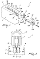
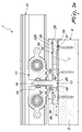
- the reference numeral 1 generally designates a support, particularly for a panel 2 of an in-wall retractable sliding door or a sliding door positioned close to the ceiling.
- the support 1 is constituted by a bracket 3 which can be associated, by way of adapted means such as screws, with a recess 4 provided longitudinally with respect to the first upper surface 5 of the panel 2 proximate to a first lateral surface 6 thereof.
- the bracket 3 has a desired length and is positioned in the recess 4 so as to arrange one of its ends 3a substantially flush with the first lateral surface 6 of the panel 2.
- the bracket 3 has, in a transverse cross-section, an ⁇ (omega)-like shape, so as to define a base 7 which is substantially as wide as the recess 4 and from which two arms 8a, 8b branch off vertically which are slightly less high than the depth of the recess 4 and are followed by two first tabs 9a, 9b which are arranged parallel to the base 7 for part of the width of the recess 4.
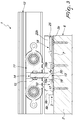
- a channel 10 is defined which is directed toward the ceiling or toward an adapted trolley 11 which is associated slideably with an adapted rail 12.
- first head 13 of a first screw 14 can be slideably associated; the threaded first shank 15 of such first screw can be associated with the trolley 11 in order to achieve the sliding of the panel 2 of the door either on the trolley 11 or on the ceiling.
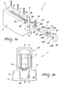
- the stop element 17 can also be constituted by a boss that is cut in half, as shown in Figures 4, 5 and 6 ; such boss is shaped substantially like a quarter of a sphere and defines a very robust stop element.
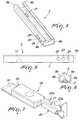
- the second lateral surface 16b of the first head 13 which is directed toward the first lateral surface 6 of the panel 2 interacts instead with an insert 18, which is shaped substantially like a parallelepiped and is adapted to eliminate the tolerance between the first head 13 and the bracket 3.
- the insert 18 is slideably and axially insertable within the channel 10 of the bracket 3; the insert 18 has substantially the same width and height as the channel 10 and a length equal to the distance between the end 3a of the bracket 3 and the stop element 17.
- the insert 18 is provided with means adapted to eliminate the tolerance between the first head 13 and the bracket 3, such means being constituted by a second tab 19 which protrudes at an end of the insert 18 which is directed toward the stop element 17 and interacts therewith, the second tab 19 being thinner than the insert 18 and lying on a plane adjacent to the base 7 of the bracket 3.
- the second tab 19 is arrangeable below the first head 13 and is adapted to propel the first head 13 upwardly, until it interacts in abutment against the two first tabs 9a, 9b of the bracket 3, and is adapted to arrange the step-like discontinuity 20 which forms between the second tab 19 and the insert 18 adjacent to and in contact with the second lateral surface 16b of the first head 13.
- teeth 23a, 23b which interact with complementarily-shaped grip means constituted by seats or holes 24 provided on each one of the two arms 8a, 8b.
- a hollow cylinder 26 which is molded integrally with the insert 18 and the function of which is to keep the second screw 25 parallel to the insert 18.
- the cylinder 26 yields sufficiently for the insert 18 to be splayed and be locked in position; indeed, the cylinder 26 increases the contrasting thickness, thus improving the locking.
- the second shank 27 of a pin 28 can be axially associated at the notch 21; the second shank 27 is adapted to splay the two wings 22a, 22b until the teeth 23a, 23b are arranged within the holes 24.
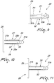
- the pin 28 is substantially T-shaped overall so as to define the second shank 27 and a square-shaped second head 29.
- the second shank 27 has a main body 30 with a circular cross-section, the ends 31a, 31b of which have a smaller diameter than the central part 32; furthermore there are, externally with respect to the main body 30 at the lateral surface of the central part 32 and according to mutually parallel directrices, a pair of lateral wings 33a, 33b, each of which has a substantially semicircular cross-section.
- Each one of the lateral wings 33a, 33b branches off at one end from the second head 29 and extends along the second shank 27 along part of its length.
- an upper wing 34 with a substantially square cross-section which branches off at one end from the second head 29 and extends along the second shank 27 for part of its length, advantageously to a greater extent than that of the pair of lateral wings 33a, 33b.
- a pair of half-cylinders 36a, 36b protrude, facing each other and molded in one piece with the insert 18, the function of which is to keep the second shank 27 of the pin 28 parallel to the insert 18 and to improve the locking of the latter to the bracket 3.
- the bulge of the central part 32 of the main body 30 of the second shank 27 prevents, owing to the presence of the lateral wings 33a, 33b and of the upper wing 34, the rotation of the pin 28, further contributing to the locking thereof.
- Figure 11 shows a possible different embodiment for the pin 28 in which the pairs of lateral wings 33a, 33b are not present on the second shank 27, and instead, externally with respect to the main body 30 and at the lateral surface of the central part 32 and according to mutually parallel directrices, a pair of flattened-out features are obtained that reduce the lateral space occupation of the main body 30 and extend along the second shank 27 for part of its length.
- the support makes it possible to keep the panel stably and securely associated with the rail, preventing it from being subjected to possible lifting or oscillations.
- the insert 18 further acts as a plug and therefore as a finishing at the first lateral surface 6 of the panel 2.
- the particular tapered shape structure of the second shank 27 of the pin 28 facilitates the insertion within the insert 18 and creates a narrower region in order to achieve the locking of the position of the pin 28.
- the support is structurally simple and low cost.
Landscapes
- Engineering & Computer Science (AREA)
- Mechanical Engineering (AREA)
- Vehicle Step Arrangements And Article Storage (AREA)
- Connection Of Plates (AREA)
Applications Claiming Priority (2)
| Application Number | Priority Date | Filing Date | Title |
|---|---|---|---|
| ITMI20142275 | 2014-12-30 | ||
| ITUB2015A004675A ITUB20154675A1 (it) | 2014-12-30 | 2015-10-14 | Dispositivo di supporto. |
Publications (1)
| Publication Number | Publication Date |
|---|---|
| EP3040501A1 true EP3040501A1 (fr) | 2016-07-06 |
Family
ID=54850160
Family Applications (1)
| Application Number | Title | Priority Date | Filing Date |
|---|---|---|---|
| EP15202151.5A Ceased EP3040501A1 (fr) | 2014-12-30 | 2015-12-22 | Support |
Country Status (2)
| Country | Link |
|---|---|
| EP (1) | EP3040501A1 (fr) |
| BR (1) | BR102015032984B8 (fr) |
Cited By (1)
| Publication number | Priority date | Publication date | Assignee | Title |
|---|---|---|---|---|
| CN107975314A (zh) * | 2018-02-05 | 2018-05-01 | 广东东泰五金精密制造有限公司 | 一种悬挂式家具滑动门 |
Citations (5)
| Publication number | Priority date | Publication date | Assignee | Title |
|---|---|---|---|---|
| CH211879A (de) * | 1939-08-08 | 1940-10-31 | Walz Wilhelm Sr | Laufgehänge für Fenster und Türen mit Gleit- und Schwenkflügeln. |
| EP0943772A2 (fr) * | 1998-03-06 | 1999-09-22 | Klein Iberica, S.A. | Structure pour le montage des portes coulissantes |
| WO2005071178A1 (fr) * | 2004-01-26 | 2005-08-04 | Peter Leitgeb | Dispositif de fixation amovible d'au moins un element plat, systeme comprenant au moins deux de ces dispositifs, et leur utilisation |
| EP1741862A2 (fr) * | 2005-06-27 | 2007-01-10 | Eclisse Srl | Dispositif de suspension pour portes coulissantes |
| EP2357305A1 (fr) * | 2010-02-15 | 2011-08-17 | Eclisse Srl | Dispositif de support et d'ancrage d'un panneau de porte coulissante rétractable dans un contrebâti |
-
2015
- 2015-12-22 EP EP15202151.5A patent/EP3040501A1/fr not_active Ceased
- 2015-12-30 BR BR102015032984A patent/BR102015032984B8/pt active IP Right Grant
Patent Citations (6)
| Publication number | Priority date | Publication date | Assignee | Title |
|---|---|---|---|---|
| CH211879A (de) * | 1939-08-08 | 1940-10-31 | Walz Wilhelm Sr | Laufgehänge für Fenster und Türen mit Gleit- und Schwenkflügeln. |
| EP0943772A2 (fr) * | 1998-03-06 | 1999-09-22 | Klein Iberica, S.A. | Structure pour le montage des portes coulissantes |
| EP0943772B1 (fr) * | 1998-03-06 | 2005-02-09 | Klein Iberica, S.A. | Structure pour le montage des portes coulissantes |
| WO2005071178A1 (fr) * | 2004-01-26 | 2005-08-04 | Peter Leitgeb | Dispositif de fixation amovible d'au moins un element plat, systeme comprenant au moins deux de ces dispositifs, et leur utilisation |
| EP1741862A2 (fr) * | 2005-06-27 | 2007-01-10 | Eclisse Srl | Dispositif de suspension pour portes coulissantes |
| EP2357305A1 (fr) * | 2010-02-15 | 2011-08-17 | Eclisse Srl | Dispositif de support et d'ancrage d'un panneau de porte coulissante rétractable dans un contrebâti |
Cited By (1)
| Publication number | Priority date | Publication date | Assignee | Title |
|---|---|---|---|---|
| CN107975314A (zh) * | 2018-02-05 | 2018-05-01 | 广东东泰五金精密制造有限公司 | 一种悬挂式家具滑动门 |
Also Published As
| Publication number | Publication date |
|---|---|
| BR102015032984B1 (pt) | 2022-02-22 |
| BR102015032984B8 (pt) | 2022-04-19 |
| BR102015032984A2 (pt) | 2016-09-13 |
Similar Documents
| Publication | Publication Date | Title |
|---|---|---|
| EP3640486B1 (fr) | Meuble | |
| USD815313S1 (en) | Slide clip with external flanges | |
| US20180177297A1 (en) | Drawer comprising a base panel, a screen, a rear wall and two lateral walls which are rigidly interconnected | |
| WO2014110134A3 (fr) | Verrouillage contre le vent de quatre-vingt-dix degrés ayant une capacité de libération ainsi que panneau de porte et ensemble porte utilisant ce dernier | |
| USD752421S1 (en) | Shower rod mounting bracket used to mount a curved shower rod | |
| EA201401301A1 (ru) | Элемент кровельного покрытия (черепицеподобный) с угловым кронштейном | |
| EP3040501A1 (fr) | Support | |
| EP3152448A1 (fr) | Connecteur pour connecter des éléments à section profilée | |
| EP3288420B1 (fr) | Tiroir assemblable pour meuble, et procédé d'assemblage dudit tiroir | |
| CA2775361A1 (fr) | Tringle superieure pour rideaux avec capuchons fixes aux extremites | |
| EP2822120B1 (fr) | Boîtier de montage | |
| MX379220B (es) | Soporte para sujetar un tirador tipo perfil. | |
| EP3121363B1 (fr) | Equerre de fixation pour cadres constitués de profilés | |
| KR101829444B1 (ko) | 커튼봉 고정구 | |
| US9955824B2 (en) | Shower door leveler | |
| EP3279038B1 (fr) | Structure de support pour plaques d'immatriculation de véhicules | |
| EP3039215B1 (fr) | Pince de fixation et procédé de fixation d'un cadre de finition contre un châssis d'une fenêtre ou similaires et fenêtre munie d'une telle pince de fixation | |
| EP2977534A1 (fr) | Rail, en particulier pour des cadres encastrées de portes coulissantes | |
| MX375206B (es) | Tapa de extremo para un limpiador. | |
| EP3284893B1 (fr) | Dispositif de fixation amelioré | |
| EP2886771B1 (fr) | Montant avant rétractable destiné à être encastré dans des trames de portes coulissantes avec élément de centrage | |
| EP2000760A1 (fr) | Porte de réfrigérateur domestique | |
| EP2998083B1 (fr) | Ensemble couteau possédant une structure de limitation | |
| EP3808920B1 (fr) | Espaceur pour isolation | |
| CA2930130C (fr) | Fixation pour un pare-soleil |
Legal Events
| Date | Code | Title | Description |
|---|---|---|---|
| PUAI | Public reference made under article 153(3) epc to a published international application that has entered the european phase |
Free format text: ORIGINAL CODE: 0009012 |
|
| AK | Designated contracting states |
Kind code of ref document: A1 Designated state(s): AL AT BE BG CH CY CZ DE DK EE ES FI FR GB GR HR HU IE IS IT LI LT LU LV MC MK MT NL NO PL PT RO RS SE SI SK SM TR |
|
| AX | Request for extension of the european patent |
Extension state: BA ME |
|
| STAA | Information on the status of an ep patent application or granted ep patent |
Free format text: STATUS: REQUEST FOR EXAMINATION WAS MADE |
|
| 17P | Request for examination filed |
Effective date: 20161110 |
|
| RAX | Requested extension states of the european patent have changed |
Extension state: ME Extension state: BA Payment date: 20161110 |
|
| RBV | Designated contracting states (corrected) |
Designated state(s): AL AT BE BG CH CY CZ DE DK EE ES FI FR GB GR HR HU IE IS IT LI LT LU LV MC MK MT NL NO PL PT RO RS SE SI SK SM TR |
|
| STAA | Information on the status of an ep patent application or granted ep patent |
Free format text: STATUS: EXAMINATION IS IN PROGRESS |
|
| 17Q | First examination report despatched |
Effective date: 20180406 |
|
| RAP1 | Party data changed (applicant data changed or rights of an application transferred) |
Owner name: ECLISSE S.R.L. |
|
| STAA | Information on the status of an ep patent application or granted ep patent |
Free format text: STATUS: THE APPLICATION HAS BEEN REFUSED |
|
| 18R | Application refused |
Effective date: 20211009 |