EP3044472B1 - Verfahren und system zur steuerung einer kupplung - Google Patents
Verfahren und system zur steuerung einer kupplung Download PDFInfo
- Publication number
- EP3044472B1 EP3044472B1 EP14784272.8A EP14784272A EP3044472B1 EP 3044472 B1 EP3044472 B1 EP 3044472B1 EP 14784272 A EP14784272 A EP 14784272A EP 3044472 B1 EP3044472 B1 EP 3044472B1
- Authority
- EP
- European Patent Office
- Prior art keywords
- clutch
- actuator
- mode
- pedal
- assistance
- Prior art date
- Legal status (The legal status is an assumption and is not a legal conclusion. Google has not performed a legal analysis and makes no representation as to the accuracy of the status listed.)
- Active
Links
Images




Classifications
-
- F—MECHANICAL ENGINEERING; LIGHTING; HEATING; WEAPONS; BLASTING
- F16—ENGINEERING ELEMENTS AND UNITS; GENERAL MEASURES FOR PRODUCING AND MAINTAINING EFFECTIVE FUNCTIONING OF MACHINES OR INSTALLATIONS; THERMAL INSULATION IN GENERAL
- F16D—COUPLINGS FOR TRANSMITTING ROTATION; CLUTCHES; BRAKES
- F16D48/00—External control of clutches
- F16D48/06—Control by electric or electronic means, e.g. of fluid pressure
-
- F—MECHANICAL ENGINEERING; LIGHTING; HEATING; WEAPONS; BLASTING
- F16—ENGINEERING ELEMENTS AND UNITS; GENERAL MEASURES FOR PRODUCING AND MAINTAINING EFFECTIVE FUNCTIONING OF MACHINES OR INSTALLATIONS; THERMAL INSULATION IN GENERAL
- F16D—COUPLINGS FOR TRANSMITTING ROTATION; CLUTCHES; BRAKES
- F16D2500/00—External control of clutches by electric or electronic means
- F16D2500/10—System to be controlled
- F16D2500/104—Clutch
- F16D2500/10406—Clutch position
- F16D2500/10412—Transmission line of a vehicle
-
- F—MECHANICAL ENGINEERING; LIGHTING; HEATING; WEAPONS; BLASTING
- F16—ENGINEERING ELEMENTS AND UNITS; GENERAL MEASURES FOR PRODUCING AND MAINTAINING EFFECTIVE FUNCTIONING OF MACHINES OR INSTALLATIONS; THERMAL INSULATION IN GENERAL
- F16D—COUPLINGS FOR TRANSMITTING ROTATION; CLUTCHES; BRAKES
- F16D2500/00—External control of clutches by electric or electronic means
- F16D2500/10—System to be controlled
- F16D2500/104—Clutch
- F16D2500/10443—Clutch type
- F16D2500/1045—Friction clutch
-
- F—MECHANICAL ENGINEERING; LIGHTING; HEATING; WEAPONS; BLASTING
- F16—ENGINEERING ELEMENTS AND UNITS; GENERAL MEASURES FOR PRODUCING AND MAINTAINING EFFECTIVE FUNCTIONING OF MACHINES OR INSTALLATIONS; THERMAL INSULATION IN GENERAL
- F16D—COUPLINGS FOR TRANSMITTING ROTATION; CLUTCHES; BRAKES
- F16D2500/00—External control of clutches by electric or electronic means
- F16D2500/30—Signal inputs
- F16D2500/306—Signal inputs from the engine
- F16D2500/3065—Torque of the engine
-
- F—MECHANICAL ENGINEERING; LIGHTING; HEATING; WEAPONS; BLASTING
- F16—ENGINEERING ELEMENTS AND UNITS; GENERAL MEASURES FOR PRODUCING AND MAINTAINING EFFECTIVE FUNCTIONING OF MACHINES OR INSTALLATIONS; THERMAL INSULATION IN GENERAL
- F16D—COUPLINGS FOR TRANSMITTING ROTATION; CLUTCHES; BRAKES
- F16D2500/00—External control of clutches by electric or electronic means
- F16D2500/30—Signal inputs
- F16D2500/306—Signal inputs from the engine
- F16D2500/3067—Speed of the engine
-
- F—MECHANICAL ENGINEERING; LIGHTING; HEATING; WEAPONS; BLASTING
- F16—ENGINEERING ELEMENTS AND UNITS; GENERAL MEASURES FOR PRODUCING AND MAINTAINING EFFECTIVE FUNCTIONING OF MACHINES OR INSTALLATIONS; THERMAL INSULATION IN GENERAL
- F16D—COUPLINGS FOR TRANSMITTING ROTATION; CLUTCHES; BRAKES
- F16D2500/00—External control of clutches by electric or electronic means
- F16D2500/30—Signal inputs
- F16D2500/308—Signal inputs from the transmission
- F16D2500/30806—Engaged transmission ratio
-
- F—MECHANICAL ENGINEERING; LIGHTING; HEATING; WEAPONS; BLASTING
- F16—ENGINEERING ELEMENTS AND UNITS; GENERAL MEASURES FOR PRODUCING AND MAINTAINING EFFECTIVE FUNCTIONING OF MACHINES OR INSTALLATIONS; THERMAL INSULATION IN GENERAL
- F16D—COUPLINGS FOR TRANSMITTING ROTATION; CLUTCHES; BRAKES
- F16D2500/00—External control of clutches by electric or electronic means
- F16D2500/30—Signal inputs
- F16D2500/312—External to the vehicle
- F16D2500/3124—Driving conditions, e.g. climbing hills, cornering, traffic
-
- F—MECHANICAL ENGINEERING; LIGHTING; HEATING; WEAPONS; BLASTING
- F16—ENGINEERING ELEMENTS AND UNITS; GENERAL MEASURES FOR PRODUCING AND MAINTAINING EFFECTIVE FUNCTIONING OF MACHINES OR INSTALLATIONS; THERMAL INSULATION IN GENERAL
- F16D—COUPLINGS FOR TRANSMITTING ROTATION; CLUTCHES; BRAKES
- F16D2500/00—External control of clutches by electric or electronic means
- F16D2500/30—Signal inputs
- F16D2500/312—External to the vehicle
- F16D2500/3125—Driving resistance, i.e. external factors having an influence in the traction force, e.g. road friction, air resistance, road slope
-
- F—MECHANICAL ENGINEERING; LIGHTING; HEATING; WEAPONS; BLASTING
- F16—ENGINEERING ELEMENTS AND UNITS; GENERAL MEASURES FOR PRODUCING AND MAINTAINING EFFECTIVE FUNCTIONING OF MACHINES OR INSTALLATIONS; THERMAL INSULATION IN GENERAL
- F16D—COUPLINGS FOR TRANSMITTING ROTATION; CLUTCHES; BRAKES
- F16D2500/00—External control of clutches by electric or electronic means
- F16D2500/30—Signal inputs
- F16D2500/314—Signal inputs from the user
- F16D2500/31406—Signal inputs from the user input from pedals
- F16D2500/31413—Clutch pedal position
-
- F—MECHANICAL ENGINEERING; LIGHTING; HEATING; WEAPONS; BLASTING
- F16—ENGINEERING ELEMENTS AND UNITS; GENERAL MEASURES FOR PRODUCING AND MAINTAINING EFFECTIVE FUNCTIONING OF MACHINES OR INSTALLATIONS; THERMAL INSULATION IN GENERAL
- F16D—COUPLINGS FOR TRANSMITTING ROTATION; CLUTCHES; BRAKES
- F16D2500/00—External control of clutches by electric or electronic means
- F16D2500/50—Problem to be solved by the control system
- F16D2500/508—Relating driving conditions
- F16D2500/5085—Coasting
-
- F—MECHANICAL ENGINEERING; LIGHTING; HEATING; WEAPONS; BLASTING
- F16—ENGINEERING ELEMENTS AND UNITS; GENERAL MEASURES FOR PRODUCING AND MAINTAINING EFFECTIVE FUNCTIONING OF MACHINES OR INSTALLATIONS; THERMAL INSULATION IN GENERAL
- F16D—COUPLINGS FOR TRANSMITTING ROTATION; CLUTCHES; BRAKES
- F16D2500/00—External control of clutches by electric or electronic means
- F16D2500/50—Problem to be solved by the control system
- F16D2500/508—Relating driving conditions
- F16D2500/50866—Parking, i.e. control of drive units during parking
-
- F—MECHANICAL ENGINEERING; LIGHTING; HEATING; WEAPONS; BLASTING
- F16—ENGINEERING ELEMENTS AND UNITS; GENERAL MEASURES FOR PRODUCING AND MAINTAINING EFFECTIVE FUNCTIONING OF MACHINES OR INSTALLATIONS; THERMAL INSULATION IN GENERAL
- F16D—COUPLINGS FOR TRANSMITTING ROTATION; CLUTCHES; BRAKES
- F16D2500/00—External control of clutches by electric or electronic means
- F16D2500/70—Details about the implementation of the control system
- F16D2500/704—Output parameters from the control unit; Target parameters to be controlled
- F16D2500/70402—Actuator parameters
- F16D2500/70408—Torque
Definitions
- the invention relates to a method and to a system for controlling a clutch.
- the invention relates more particularly to clutches, the control of which can be ensured by an actuator connected to an actuator pedal associated with a position sensor so as to allow the driver to keep control of the clutch operations while benefiting from functionalities. clutch control assistance.
- Such a control method is for example described in the document FR 2812919 .
- the control method described in this document makes it possible to increase the comfort, precision and speed of the clutch control.
- the method notably provides for controlling the actuator so as to accelerate the disengagement with respect to the movement of the pedal over dead strokes having no effect on the transmissible torque and to slow the disengagement with respect to the displacement. of the pedal during a useful stroke during which the torque transmitted by the clutch is modified.
- this document provides for equipping the vehicle with a selector making it possible to select between a manual piloting mode in which the actuator is moved according to the position of the pedal and an automatic mode in which the transmission ratio is changed by moving a gear lever, the disengagement and the clutch then being controlled automatically as a function of the engine speed, the vehicle speed and the position of the accelerator pedal or of a component controlled by the accelerator pedal.
- the invention aims to remedy these problems by proposing a method for controlling a clutch making it possible to benefit from advanced assistance functions while allowing the driver to control the clutch manually by means of an actuating pedal.
- control unit is arranged to, in assistance mode, analyze the position signal of the actuating pedal of the clutch and the position signal of the actuator and reactivate the control mode.
- manual control in response to the detection of a position of the actuator pedal representative of a position of the actuator identical to or more distant in the direction of the disengaged position than the position of the actuator.
- the motor vehicle shown in the figure 1 , comprises a combustion engine 1 whose output shaft or crankshaft is connected to an input shaft 3 of a gearbox 2 via a clutch 4.
- a combustion engine 1 whose output shaft or crankshaft is connected to an input shaft 3 of a gearbox 2 via a clutch 4.
- the torque transmission between the crankshaft and the input shaft 3 of gearbox 2 is secured when clutch 4 is in an engaged position and is interrupted when clutch 4 is in disengaged position.
- the vehicle comprises a clutch actuation pedal 19 pivotally mounted on the vehicle chassis between a rest position and an extreme depressed position.
- the clutch actuator pedal 19 is associated with a position sensor 20 able to deliver a position signal of the pedal 19.
- a clutch actuator 14 is able to act on the position of the clutch release bearing in order to to move the clutch 4 from an engaged position to a disengaged position, or vice versa.
- the clutch actuator 14 is connected to a battery 15 of the vehicle via a power supply network 16 and to a control unit 17 via a multiplexing bus 18.
- the control unit. piloting 17 is integrated into an engine control computer which houses the software resources for piloting the clutch and an assistance supervision module.
- the control unit 17 takes into account the position of the pedal 19 to control the clutch actuator 14.
- the clutch 4 is in the engaged position. and transmits the engine torque between the crankshaft and the input shaft 3 of the gearbox 2.
- the actuator 14 is controlled, depending on the position signal from the pedal 19, so as to move the clutch release bearing to a disengaged position in which the transmission of torque between the engine 1 and the input shaft 3 of the gearbox 2 is interrupted.
- the gearbox 2 comprises an output shaft 5, parallel to the input shaft 3, which is equipped with idle gears 6 cooperating with gear gears 7 carried by the input shaft 3.
- the drive shaft output 5 carries synchronization and clutch means 8 making it possible to secure the idler gears 6 in rotation to the output shaft 5, so as to engage a transmission ratio between the input shaft 3 and the output shaft 5 of the gearbox.
- the output shaft 5 cooperates with an input pinion 10 of the differential in order to transmit the torque to the wheels 9a, 9b.
- a gear lever 20 makes it possible to manually select and engage the synchronization means 8.
- the gear lever 20 is associated with a position sensor 21 making it possible to detect the selected gear as well as a change of gear.
- the vehicle is equipped with numerous sensors, such as a sensor 11 for measuring the engine speed, a sensor 12 for measuring the speed of rotation of the input shaft 3 of the gearbox 2 and / or a sensor 13 for measuring the speed of rotation of the output shaft 5 of the gearbox 2.
- sensors such as a sensor 11 for measuring the engine speed, a sensor 12 for measuring the speed of rotation of the input shaft 3 of the gearbox 2 and / or a sensor 13 for measuring the speed of rotation of the output shaft 5 of the gearbox 2.
- the motor vehicle further comprises a steering wheel 22, a brake pedal 23 associated with a sensor 24 capable of delivering a signal representative of the position of the brake pedal, a brake control module of the ABS type 28, a pedal 25 d accelerator associated with a position sensor 26 of the accelerator pedal, a parking brake 27, a parking brake management module 29 and an automatic parking assistance module 30.
- the vehicle is furthermore equipped with an assistance mode selection means 31 allowing the driver to choose whether he wishes to benefit from one, several or all of the assistance modes.
- the selection means 31 may be a switch arranged on the dashboard and / or a configuration panel comprising a menu accessible via an electronic interface of the on-board control and allowing a selection of the assistance options at the request of the driver.
- the options of the assistance modes are also configurable by means of an application capable of communicating with a dedicated application of a remote telematics / telephone device, of the “Smartphone” type.
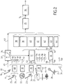
- the figure 2 illustrates a functional diagram of a clutch control unit.
- the signal 45 for the position of the actuating pedal 19 delivered by the position sensor 20 is transformed by a conversion module 33 into a torque setpoint signal 63 which can be transmitted by the clutch.
- the conversion module 33 generates a transmissible torque setpoint signal 63 from a calibratable curve 34 representing the transmissible torque as a function of the position of the pedal 19 for actuating the clutch.
- Such a conversion module 33 makes it possible to optimize the comfort, precision and speed of the clutch control by adapting the progressiveness of the clutch as a function of the travel of the pedal 19.
- the transmissible torque setpoint signal 63 is transmitted to a clutch control module 35 which generates, as a function of this transmissible torque setpoint signal 63, a signal 74 for the actuator position setpoint.
- the actuator position reference signal 74 is then transmitted to a module 36 for controlling the actuator which will control the position of the actuator 14 as a function of a signal representative of the position of the actuator, generated by an actuator position sensor.
- the control unit comprises a module 37 for supervising the assistance.
- the assistance supervision module 37 is designed to determine the appropriate assistance mode as a function of the driving conditions of the vehicle and / or of the position of the vehicle control equipment and to emit an activation signal. a mode of assistance in the direction of the clutch control module 35 so that the latter controls the clutch 4 as a function of a reference signal determined by one of the modules 38, 39, 40, 41, 42, 43, 44, for implementing an assistance function.
- the assistance supervision module 37 receives numerous information signals representative of the driving conditions of the vehicle and of the position of the vehicle control equipment allowing it to implement the assistance functions.
- the assistance supervision module 37 comprises a plurality of modules 38, 39, 40, 41, 42, 43, 44, for implementing an assistance function which are arranged to deliver a control signal.
- torque setpoint transmissible to the clutch control module 35, as a function of one or more of the signals mentioned above.
- the assistance modules 38, 39, 40, 41, 42, 43, 44 are in particular arranged to communicate with the engine control unit 48 in order to transmit torque setpoints to the heat engine or engine shutdown requests and / or with the parking brake management module 29.
- the clutch control unit can be integrated into the engine control unit 48 and / or be integrated into the electronic card of the clutch actuator 14.
- the assistance supervision module 37 and its assistance modules 38, 39, 40, 41, 42, 43, 44 are integrated into the engine control unit 48 while the module 36 of control of the actuator is housed in the electronic card of the actuator 14.
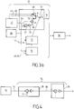
- the figure 3a illustrates in detail the operation of the clutch control module 35 according to one embodiment.
- the clutch control module 35 receives, on the one hand, a transmissible torque setpoint signal 63 established as a function of the position of the clutch actuation pedal 19 and, on the other hand, a signal 64 of the transmissible torque setpoint established by one of the assistance modules 38, 39, 40, 41, 42, 43, 44 of the assistance supervision module 37.
- the clutch control module 35 also receives, from the assistance supervision module 37, a signal 65 for activating an assistance mode.
- the clutch control module 35 is equipped with selection means 66 which make it possible to choose between the signal 63 of the transmissible torque setpoint established as a function of the position of the clutch actuation pedal 19 and the signal 64 of transmissible torque setpoint established by one of the assistance modules 38, 39, 40, 41, 42, 43, 44, as a function of the signal 65 for activating an assistance mode.
- the setpoint 64 established by one of the assistance modules 38, 39, 40, 41, 42, 43, 44 is compared by comparison means 67 with a real-time estimate of the torque transmitted by the clutch, generated by a module 68 for estimating the transmissible torque.
- a module 68 for estimating the transmissible torque is, for example, described in the document FR 2863327 .
- a correction signal 69 is established by a corrector 70 as a function of the result of the comparison carried out by the comparison means 67.
- An adder 71 makes it possible to deliver a corrected signal 72 of the torque setpoint that can be transmitted in function of the reference signal 64 established by one of the assistance modules and of the correction signal 69.
- the clutch control module 35 also comprises a conversion module 73 making it possible to convert the transmissible torque setpoint signal 63 established as a function of the position of the pedal 19 or the corrected torque setpoint signal 72 transmissible, in an actuator position reference signal 74.
- the conversion module 73 implements a mathematical model whose parameters are updated by the module 75.
- the module 75 is arranged to update the parameters of the model according to the estimate of the transmissible torque generated by the module 68. , an estimate of the temperature of the clutch established by a module 76 for estimating the temperature of the clutch and a signal 77 of the position of the actuator.
- the temperature estimation module 76 estimates the temperature of the clutch as a function of the estimate of the transmissible torque produced by the module 68, of the engine speed signal 46 and of the signal 56 representative of the speed of rotation of the engine. input shaft 3 of the gearbox.
- a clutch temperature estimation module is, for example, described in the document FR 2936034 .
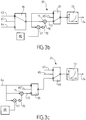
- a selection means 96 makes it possible to choose between the transmissible torque setpoint signal 63 established as a function of the position of the pedal 19 and the transmissible torque setpoint signal 64 established by one of the assistance modules 38, 39 , 40, 41, 42, 43, 44, as a function of the signal 65 for activating an assistance mode.
- the clutch control module 35 comprises a second selection means 97 making it possible to choose between the setpoint signal at the output of the selection means 96 and a corrected torque setpoint signal 72 transmissible established on the basis of the torque setpoint signal at the output of the selection means 96, corrected by means of the comparison means 67, the corrector 70 and the adder 71 as described in relation to the figure 3a .
- a correction loop activation signal 65 ′ generated by the assistance supervision module 37 makes it possible to choose between the two signals.
- the signal corrected 72 by means of the correction loop is used during engagement operations while the other signal is used during disengagement operations.
- the clutch control module 35 comprises a conversion module 73 making it possible to convert the transmissible torque reference signal into a signal 74 for the actuator position reference.
- a selection means 98 makes it possible to choose between the transmissible torque setpoint signal 64 established by one of the assistance modules 38, 39, 40, 41, 42, 43, 44, and a corrected signal 72 of the torque setpoint.
- transmissible torque established on the basis of the signal 64 corrected by means of the comparison means 67, of the corrector 70 and of the adder 71 as described in relation to the figure 3a , as a function of a correction loop activation signal 65 "generated by the assistance supervision module 37.
- the clutch control module 35 comprises a second selection means 99 making it possible to choose between the transmissible torque setpoint signal 63 established as a function of the position of the pedal 19 and the transmissible torque setpoint signal at the output of the selection means 98.
- the corrected signal 72 by means of the correction loop is used during clutch operations while the other signal is used during disengagement operations.
- the figure 4 illustrates, in detail, the operation of the module 36 for controlling the clutch actuator.
- the clutch actuator control module 36 comprises a position corrector 78 which generates an actuator supply current setpoint 80 as a function of a comparison between the actuator position setpoint signal 74 and a signal 77 representative of the position of the actuator. Furthermore, the clutch actuator control module 36 comprises a corrector 79 which compensates for the error between the setpoint 79 supply current and a measurement of the actuator supply current 14.
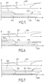
- the figure 5 illustrates the implementation of the freewheel assistance mode making it possible to disengage the clutch 4 in order to use the kinetic energy of the motor vehicle without a resistive torque of the motor 1 braking the vehicle.
- the assistance supervision module 37 and / or the engine control unit 38 determines, on the one hand, that the driving conditions of the vehicle are appropriate to activate the freewheel assistance mode, and that, on the other hand, the clutch actuation pedal 19 is in an engaged rest position 205, and that the accelerator pedal 25 is in its rest position 206 or in a position below a threshold of depression such that no torque command of the heat engine other than maintaining idle is generated by the engine computer, the assistance module 37 activates the freewheel module 43 and delivers, to the control module 35 of the clutch, an assistance activation signal 65. The clutch is then controlled as a function of a torque setpoint generated automatically by the freewheel module 43.
- the driving conditions of the vehicle which allow the passage from manual piloting mode to freewheel assistance mode include speeds between two predetermined thresholds, for example between 0 and 50 km / h and / or between 110 and 130km / h, and / or decelerations below a threshold.
- the speed thresholds can be determined as a function of the gear ratio engaged, the topology of the road, road sign information and / or traffic conditions given by a navigation aid system.
- the deceleration thresholds can be determined as a function of the inclination of the road likely to be obtained via an inclinometer type sensor or by a navigation system providing topological data.
- the transmission supervision module 37 also ensures that the freewheel assistance mode has been selected by the driver before activating the freewheel module 43 and / or deliver an assistance activation signal.
- the freewheel module 43 controls the clutch actuator 14 to move the clutch 4 to a disengaged position (curve 202) in which the torque transmission between the output shaft of the motor 1 and the shaft input 3 of gearbox 2 is interrupted.
- the freewheel module 43 develops, in a first phase, a torque setpoint transmissible by the clutch 4 corresponding to the engine torque 203 so that the torque transmissible by the clutch 202 reaches the value of the engine torque 203 then, in a second phase, the freewheel module 43 delivers a decreasing transmissible torque setpoint making it possible to gradually reduce the engine torque 203 until the clutch is disengaged.
- the freewheel module 43 delivers to the motor control unit 48 a setpoint for the progressive reduction of the motor torque 203.
- the freewheel module 43 When the clutch 4 is completely disengaged and the transmissible torque 202 is zero, the freewheel module 43 generates a setpoint for switching off the engine 1. The speed 201 of the engine 1 is then zero. The vehicle is then coasting and saves the quantity of fuel necessary to keep the engine 1 in operation, which makes it possible to significantly reduce carbon dioxide emissions. Note that, insofar as the engine 1, at a standstill, is uncoupled from the input shaft 3 of the gearbox 2, the transmission ratio can remain engaged.
- the acceleration or deceleration of the vehicle is determined and compared to a threshold.
- the acceleration or deceleration of the vehicle can be determined by means of the signal representing the speed 200 of the input shaft 3 of the gearbox 2 if a transmission ratio is engaged or by means of 'a signal 53 representative of the speed of the wheels supplied by the brake control module of the ABS type 28.
- the motor 1 is put back into operation and the wheel module free 43 controls the clutch actuator 14 to return the clutch 4 to an engaged position.
- the freewheel module 43 controls the clutch actuator 14 to an engaged position before restarting the engine 1 so that the clutch 4 makes it possible to start the engine 1 without using the starter.
- the figure 6 illustrates the operation of the freewheel module with engine brake 44.
- This assistance mode also makes it possible to disengage the clutch 4 in order to use the kinetic energy of the motor vehicle when characteristic driving conditions have been detected by braking the vehicle. or by limiting its acceleration on a slope.
- a movement of the brake pedal 24 towards its depressed position makes it possible to switch from freewheel assistance mode to motor braking freewheel assistance mode, at least part of the braking torque then being supplied by the motor when the motor is stationary.
- the restart of the heat engine then only takes place when the accelerator actuator pedal is depressed.
- the motor brake freewheel module 44 determines a torque setpoint signal 64 that can be transmitted by the clutch as a function of the speed, acceleration or deceleration of the vehicle.
- the torque setpoint 64 transmitted by the clutch corresponds to the resistive torque necessary to reach the speed, deceleration or acceleration setpoint of the vehicle.
- Such an assistance mode is particularly advantageous in that it allows the battery to be recharged during the vehicle braking phases.
- the figures 7 , 8, 9 and 10 illustrate the conditions for interrupting the freewheel assistance mode or the freewheel assistance mode with engine brake.
- the figure 7 illustrates an interruption of a freewheel or freewheel assistance mode with engine brake when the driver operates the clutch actuation pedal 19, the position of which is represented by the curve 205.
- the assistance supervision module 37 analyzes the position signal of the clutch actuation pedal 19 and determines whether the position of the clutch actuation pedal 19 is representative of a position. of the actuator 14 identical or more distant in the direction of the disengaged position than the actual position 204 of the actuator 14.
- the figure 8 illustrates an interruption of a freewheel or freewheel assistance mode with engine braking when the driver operates the accelerator actuator pedal, the position of which is represented by curve 206.
- the motor 1 is put back into operation via the starter and the actuator 14 is controlled to return the clutch 4 to an engaged position.
- the engine control unit 48 In order to avoid a sudden increase in the engine speed 203, the engine control unit 48 generates a progressive increase in engine torque setpoint 203 while the transmissible torque setpoint of the clutch is increasing.
- the actuator 14 is then returned to its position corresponding to the rest position of the pedal 19 for actuating the clutch.
- the manual piloting mode is reactivated and the actuator 14 follows the will of the driver via the actuation of the pedal 19 for actuating the clutch.
- the figure 9 illustrates an interruption of a freewheel or freewheel assistance mode with engine brake when a new transmission ratio is engaged by the driver (curve 207).
- the heat engine 1 is restarted, either by using the starter or by controlling the clutch 4 to its engaged position so that the torque transmission between the The input shaft 3 of the gearbox and the crankshaft allow engine 1 to be restarted.
- the transmissible torque setpoint is gradually increased until a transmissible torque setpoint is reached corresponding to the maximum transmissible torque, i.e. transmissible torque corresponding to the rest position of the clutch actuation pedal 19.
- the manual piloting mode is reactivated and the actuator 14 follows the will of the driver via the actuation of the pedal 19 for actuating the clutch.
- the figure 10 illustrates an interruption of a freewheel or freewheel assistance mode with engine brake, when the driver actuates the brake pedal 23, the position of which is represented by curve 208.
- This scenario is substantially identical to that described in relation to the figure 9 . Indeed, as soon as a movement of the brake pedal is detected, the engine 1 is restarted, either by using the starter, or by controlling the clutch 4 to its engaged position. The transmissible torque setpoint is gradually increased up to reach a transmissible torque setpoint corresponding to the maximum transmissible torque.
- the manual piloting mode is reactivated and the actuator 14 follows the will of the driver via the actuation of the pedal 19 for actuating the clutch.
- the figures 11 and 12 illustrate the operation of the module 38 for filtering the vibrations generated by the motor 1.
- This module 38 aims to filter the acyclisms of the engine 1 by maintaining the clutch 4 in a slipping position in which there is a slip between the crankshaft of the engine 1 and the input shaft 3 of the gearbox.
- the figure 12 is a three-dimensional map illustrating a slippage setpoint 210 of the clutch as a function of the engine speed 201 and the engine torque 203.
- the slip setpoint 210 is representative of a relative rotational speed of the crankshaft with respect to the shaft input 3 of the gearbox.
- the vibration filtration assistance mode is activated. Therefore, as shown in the figure 11 , the vibration filtration module 38 generates a transmissible torque setpoint signal 202 slightly lower than the engine torque 203 so as to generate a slip and a relative speed of rotation between the engine speed 201 and the speed 200 of the shaft. gearbox input 3.
- the transmissible torque setpoint 202 is controlled so as to obtain a slip corresponding to the slip setpoint value established as a function of the engine speed 201 and of the engine torque 203.
- the actuator 14 is controlled as a function of a transmissible torque setpoint corresponding to the maximum transmissible torque and to the rest position of the pedal 19 for actuating the. clutch.
- the vibration filtration assistance mode is interrupted and the manual control mode activated, when the clutch actuation pedal 19 is moved to a position representative of a position of the actuator 4 identical or more distant in the direction of the disengaged position than the position of the actuator 4 or by manipulating the gear lever 20, when the gear change assistance mode has been chosen by the driver via the selection means 31.
- the vibration filtration assistance mode is interrupted as a function of the temperature of the clutch, when the slipping of the clutch has led to the clutch heating up above a threshold.
- the temperature of the clutch can be determined via a sensor, as a function of the dissipated energy or from a model estimating t the temperature of the clutch.
- Such an interruption of an assistance mode can also be provided for the freewheel assistance mode with engine brake described above or for a vehicle take-off assistance mode which will be described below.
- the figure 13 illustrates the operation of the module 42 for assisting in changing the transmission ratio making it possible to change the transmission ratio without acting on the pedal 19 for actuating the clutch.
- the signal 213 representative of a change in transmission ratio and the signal 214 representative of the selected transmission ratio are analyzed and the transmission ratio change assistance mode is activated when the analysis of said signals 213, 214 makes it possible to detect an intention to change the transmission ratio while the position 205 of the clutch actuation pedal 19 is at rest.
- the gear change assistance mode is activated when a signal 212 representative of a gear change advice is emitted by the engine control unit 48.
- the gear change assistance module 42 controls a displacement of the clutch by developing a transmissible torque setpoint slightly greater than the engine torque 203.
- the transmissible torque setpoint is here determined as a function of the engine torque 203 and d 'a safety coefficient making it possible to ensure that the clutch 4 does not slip if a sudden demand for additional torque is generated.
- the gear change assistance module 42 controls the clutch actuator 14 to return the clutch 4 to an engaged position and communicates with the engine control unit 48 in order to progressively restore an engine torque 203 representative of the position 206 of the accelerator actuation pedal 25.
- the transmission ratio change is therefore effected without the driver having to manipulate the pedal 19 for actuating the clutch.
- the actuator 14 is in a position corresponding to the maximum transmissible torque and to the rest position of the pedal 19 for actuating the clutch.
- the figure 14 illustrates the operation of the idle travel assistance module 42 allowing automatic operation of the clutch 4 in idling travel without action on the clutch actuation pedal 19.
- this assistance mode can be selected via the assistance mode selection means 31.
- the brake pedal 23 When the vehicle is stationary, the brake pedal 23 is in the depressed position, the idle driving assistance module 42 is activated and controls the clutch 4 to its disengaged position when the first transmission ratio is then engaged. that the clutch actuation pedal 19 remains in the rest position. Subsequently, when the brake pedal 23 returns to its rest position while the accelerator pedal 25 and the clutch actuating pedal 19 are in the rest position and the parking brake 27 is not not activated, the idle driving assistance module 42 controls the clutch 4 to an engaged position.
- the vehicle moves forward at a low speed, for example of the order of 5 km / h. If the brake pedal 23 is depressed again then the idle rolling assistance module 42 again controls the clutch to a disengaged position while the clutch actuation pedal 19 remains in the rest position. Thus, in the idle driving assistance mode, the driver can manage the speed of the vehicle, only with the brake pedal 23, without any action on the clutch actuation pedal 19.
- the figures 15 and 16 illustrate the vehicle takeoff assistance mode without action on the clutch pedal.
- This assistance mode allows the vehicle to take off to obtain a speed greater than the engine idling speed.
- This assistance mode can for example be selected via the assistance mode selection means 31.
- the take-off assistance module 41 When the vehicle is stationary, the brake pedal 23 is in the depressed position, the take-off assistance module 41 is activated and drives the clutch 4 to its disengaged position when the first transmission ratio is engaged while the clutch actuation pedal remains in the rest position.
- the take-off assistance module 41 generates a torque signal transmissible by the clutch corresponding to the engine torque 203.
- the transmissible torque signal corresponding to the engine torque 203 can be determined either according to the will of the driver, that is to say according to the position 206 of the accelerator pedal 25, or as a function of the engine torque 203 estimated by the engine control unit 48.
- the transmissible torque signal is delayed by a time delay relative to the engine torque 203 so as to reach a point of operation corresponding to the vehicle acceleration desired by the driver.
- the take-off assistance module 41 When the engine speed 201 and the speed of the input shaft of the gearbox 200 are close to being synchronized, the take-off assistance module 41 generates a transmissible torque setpoint slightly lower than the engine torque 203 in order to allow progressive engagement without generating oscillation in the transmission, detrimental to comfort.
- the take-off assistance module 41 controls the clutch actuator 14 by developing a transmissible torque setpoint corresponding to the maximum transmissible torque and in the rest position of the clutch actuation pedal 19.
- Take-off assistance is also interrupted if the driver actuates the clutch pedal 19 and / or the gear lever 20 or if stalling or vehicle stopping conditions are detected.
- the figure 16 illustrates a vehicle take-off assistance mode with interaction of a parking brake 27 controlled by a parking brake management module 29.
- the clutch control module 35 communicates with the management module of the parking brake 29 and the parking brake 29 is only deactivated when the torque transmitted by the clutch is equal to or greater than the torque of the parking brake 29.
- the idle taxiing assistance mode and / or the vehicle take-off assistance mode is activated by a signal coming from the automatic parking assistance module 30.
- the figure 17 illustrates an anti-stall assistance mode making it possible to avoid stalling of the engine 1 due to an absence of operation of the pedal 19 for actuating the clutch by the driver.
- the anti-stall module 39 controls a displacement of the clutch 4 in direction of the disengaged position by generating a torque setpoint 202 transmissible by the clutch slightly greater than the engine torque 203.
- the speed threshold is variable as a function of the deceleration of the vehicle, the greater the deceleration of the vehicle and the more the speed threshold will be important.
- the anti-stall module 39 determines a decrement in the torque transmitted by the clutch making it possible to achieve a zero clutch torque for a vehicle speed substantially equal to the vehicle speed corresponding to the idle speed and controls the clutch actuator 14 as a function of the decrement of transmissible torque thus determined.
- the figures 18a, 18b and 18c illustrate the position 205 of the clutch actuating pedal 19 and the position 204 of the clutch actuator when the control unit is in an assist mode ( figure 18a ), when the pilot unit is in manual pilot mode ( figure 18b ) and when the clutch actuation pedal is operated during an assist mode ( figure 18c ).
- the clutch actuation pedal 19 In assistance mode, shown on the figure 18a , the clutch actuation pedal 19 remains in the rest position while the actuator position 204 is controlled automatically. In manual piloting mode, shown on figure 18b , the clutch actuator 14 is controlled as a function of a signal representative of the position 205 of the clutch actuation pedal 19.
- the automatic assist mode is suspended and position 204 of the clutch actuator 14 remains stable until the pedal 19 returns to its rest position or the position 205 of the pedal 19 is representative of a position of the actuator 14 identical or further away in the direction of the disengaged position than the position 204 of the actuator 14.
- the automatic assistance mode is reactivated.
- the position 205 of the pedal 19 is representative of a position of the actuator identical to or more distant in the direction of the disengaged position than the position 204 of the actuator 14
- the manual control mode is activated. and the actuator 14 is controlled as a function of a signal representative of the position of the pedal 19 for actuating the clutch.
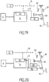
- the figures 19 and 20 schematically illustrate various embodiments of a clutch actuation pedal 19 and of a clutch actuator 14 allowing the implementation of the invention.
- the clutch actuation pedal 19, shown in figure 19 is pivotally mounted on the vehicle chassis between a rest position and an extreme depressed position.
- the angular travel of the pedal 19 is delimited by stops 81, 82 respectively defining the rest position and the extreme depressed position.
- Return means 83 are arranged to return the pedal 19 to its rest position.
- the return means 83 comprise one or more springs, the characteristics of which are defined as a function of ergonomic criteria.
- a position sensor 20 is associated with the pedal 19 and makes it possible to deliver a signal 45 representative of the position of the pedal.
- the position sensor 20 is connected to an electronic card 84 associated with the actuator 14 and communicating via a multiplexing bus 18 with the control unit 17.
- the actuator 14 acts on the stopper. clutch 4, via a mechanical link or via a hydraulic link, in order to move the clutch 4.
- the embodiment, illustrated on figure 20 is substantially similar to that described in relation to the figure 19 but also comprises a force feedback actuator 85 making it possible to exert on the pedal 19 an adjustable resistant force.
- the resistant force can in particular be determined as a function of the position of the pedal, the direction of movement of the pedal, life situations, the user or others.
- the force feedback actuator 85 is supplied electrically by the electronic card 84 associated with the actuator 14 and controlled by force by the control unit 17.
- the sensor position 20 is integrated into the force feedback actuator 85.
- the electronic card 85 of the actuator 14 comprises an electronic power module 87, connected to the vehicle battery via an electrical supply circuit 16, intended to supply the motor 86, 92 of the actuator, and the actuator control module 36 able to control the electronic power module 87 in order to control the motor.
- the electronic card 85 is connected to a brushed direct current motor 86.
- the electronic card 85 is connected to a harness connector 94 ensuring the connection of the electronic card 85, to an electrical supply network 16 connected to the battery 15 of the vehicle and to a multiplexing bus 18.
- the harness connector 94 can also ensure the connection of the electronic card 85 to one or more external sensors, such as a sensor 12 for measuring the speed of rotation. of the input shaft 3 of the gearbox
- the electronic card 85 comprises an electrical power distribution and / or regulation device 95, connected to the battery 15 of the vehicle via the connector 94 and capable of delivering the voltages and powers suitable for supplying the electrical components housed on the device. electronic card 85.
- the electronic card 85 further comprises an electronic power module 87 providing the electric power supply to the brush motor 36 and a programmable controller, such as a microcontroller 88, serving in particular as a control module for the actuator.
- a programmable controller such as a microcontroller 88
- the power electronic module 87 comprises an H-bridge with MOS transistors.
- the electronic card 85 is equipped with a multiplexing driver 89 which is arranged to manage the communications, incoming or outgoing, through the multiplexing bus 18 and communicates with a dedicated interface of the microcontroller 88.
- the microcontroller 88 is thus capable of communicating with the control unit 17, and in particular of receiving a setpoint signal for controlling the actuator.
- the electronic card 85 houses one or more internal sensors 90, 91 capable of delivering a signal representative of a physical parameter of the electromechanical actuation device.
- the electronic card 85 houses a position sensor 90 of the actuator 14 and a sensor 91 measuring the supply current of the brush motor 86. It is also possible to equip the actuator with other sensors such as a temperature measurement sensor, for example.
- the position sensor 90 comprises a detection element supported on the electronic card 85 and arranged vis-à-vis a target mounted on a movable element in rotation of the kinematics of the actuator 14.
- the position sensor 90 is able to transmit to the microcontroller 88 a signal representative of the position of the actuator.
- This signal is for example an analog signal or a pulse width modulated signal.
- the target may be a permanent magnet and the sensing element a hall effect probe.
- the microcontroller 88 is arranged to control the electronic power module 87 ensuring the electric power supply to the motor 86 by means of logic signals or of pulse width modulation.
- the microcontroller 88 controls the electronic power module 87 as a function of the reference signal 74 received from the clutch control module 35 and the signals received by the sensors 90, 91.
- the electronic card 85 is connected to a motor 92 with brushless permanent magnets.
- the architecture of the electronic card 85 is substantially similar to that described in relation to the figure 21 .
- the motor 92 being a three-phase current motor
- the power electronic module 87 comprises a three-phase bridge inverter.
- a sensor of switching 93 is mounted on the motor 92 and makes it possible to deliver, to the microcontroller 88, a signal representative of the position of the motor.
Landscapes
- Engineering & Computer Science (AREA)
- General Engineering & Computer Science (AREA)
- Physics & Mathematics (AREA)
- Fluid Mechanics (AREA)
- Mechanical Engineering (AREA)
- Hydraulic Clutches, Magnetic Clutches, Fluid Clutches, And Fluid Joints (AREA)
- Control Of Driving Devices And Active Controlling Of Vehicle (AREA)
- Control Of Vehicle Engines Or Engines For Specific Uses (AREA)
Claims (14)
- Verfahren zur Steuerung einer Kupplung (4), die zwischen der Abtriebswelle eines Motors und der Eingangswelle (3) eines Getriebes eines Kraftfahrzeugs angebracht ist, mittels:- eines Pedals (19) zur Betätigung der Kupplung, das zwischen einer Ruheposition und einer vollständig niedergetretenen Position beweglich ist;- eines Sensors (20), der dem Pedal (19) zugeordnet ist und geeignet ist, ein Positionssignal des Pedals zu liefern;- eines Aktuators (14), der dafür ausgelegt ist, die Kupplung (4) zwischen einer eingekuppelten Position und einer ausgekuppelten Position zu betätigen; und- einer Steuereinheit (17), die dafür ausgelegt ist, in einem Handsteuerungsmodus den Aktuator (14) in Abhängigkeit von dem Positionssignal des Pedals zu steuern und in wenigstens einem Assistenzmodus den Aktuator (14) automatisch zu steuern, während das Pedal (19) zur Betätigung der Kupplung in seiner Ruheposition verbleibt;wobei das Verfahren zur Steuerung umfasst:- Analysieren der Fahrbedingungen des Fahrzeugs, um charakteristische Fahrbedingungen zu erkennen, die den Übergang vom Handsteuerungsmodus zum Assistenzmodus gestatten;- Analysieren des Positionssignals des Pedals (19) zur Betätigung der Kupplung, um zu erkennen, ob sich das Pedal (19) in der Ruheposition befindet; und- Aktivieren des Assistenzmodus, in welchem der Aktuator (14) automatisch in die ausgekuppelte Position der Kupplung gesteuert wird, in Reaktion auf die Erkennung charakteristischer Fahrbedingungen und der Ruheposition des Pedals (19) .
- Verfahren zur Steuerung nach Anspruch 1, wobei im Assistenzmodus das Positionssignal (45, 205) des Pedals (19) zur Betätigung der Kupplung und ein Positionssignal (204) des Aktuators (104) analysiert werden und der Handsteuerungsmodus in Reaktion auf die Erkennung einer Position des Pedals (19) wieder aktiviert wird, die für eine identische Position des Aktuators repräsentativ ist oder weiter entfernt in Richtung der ausgekuppelten Position als die Position des Aktuators (14) ist.
- Verfahren zur Steuerung nach Anspruch 1 oder 2, wobei der Assistenzmodus und die Steuerung des Aktuators in Reaktion auf eine Erkennung einer Bewegung des Pedals (19) zur Betätigung der Kupplung ausgesetzt werden, bis der Assistenzmodus in Reaktion auf die Erkennung einer Rückkehr des Pedals (19) zur Betätigung der Kupplung in seine Ruheposition wieder aktiviert wird, oder bis der Handsteuerungsmodus in Reaktion auf die Erkennung einer Position des Pedals (19) zur Betätigung aktiviert wird, die für eine identische Position des Aktuators repräsentativ ist oder weiter entfernt in Richtung der ausgekuppelten Position als die Position des Aktuators (14) ist.
- Verfahren zur Steuerung nach einem der Ansprüche 1 bis 3, wobei im Assistenzmodus ein Sollwert des von der Kupplung (4) übertragbaren Drehmoments bestimmt wird und der Aktuator (14) in Abhängigkeit von einem Sollwert des von der Kupplung übertragbaren Drehmoments und von einer Echtzeitschätzung des von der Kupplung übertragbaren Drehmoments gesteuert wird.
- Verfahren zur Steuerung nach einem der Ansprüche 1 bis 4, wobei im Handsteuerungsmodus das Positionssignal des Pedals (19) zur Betätigung der Kupplung in einen Sollwert des von der Kupplung übertragbaren Drehmoments umgewandelt wird und der Aktuator (14) in Abhängigkeit von diesem Sollwert des übertragbaren Drehmoments gesteuert wird.
- Verfahren zur Steuerung nach einem der Ansprüche 1 bis 5, wobei der aktivierte Assistenzmodus ein Freilaufmodus ist, in welchem der Aktuator (14) so gesteuert wird, dass er die Kupplung (4) in eine ausgekuppelte Position bewegt, in welcher der Übertragung des Drehmoments zwischen der Abtriebswelle des Motors und der Eingangswelle (3) des Getriebes unterbrochen ist, und eine Anweisung zum Abstellen des Motors (1) erzeugt wird, wenn die Übertragung des Drehmoments unterbrochen ist, wobei die Erkennung der charakteristischen Fahrbedingungen, die den Übergang vom Handsteuerungsmodus zum Freilauf-Assistenzmodus gestatten, insbesondere durchgeführt wird, indem bestimmt wird, ob die Geschwindigkeit des Fahrzeugs zwischen zwei Geschwindigkeitsschwellenwerten liegt, und/oder bestimmt wird, ob die Verzögerung niedriger als ein Verzögerungsschwellenwert ist,
wobei die Geschwindigkeitsschwellenwerte insbesondere in Abhängigkeit von dem eingelegten Getriebegang, von der Topologie der Straße, von Verkehrszeicheninformationen und/oder von Verkehrsbedingungen bestimmt werden und der Beschleunigungsschwellenwert insbesondere in Abhängigkeit von einer Angabe zur Neigung der Straße bestimmt wird, die über einen Neigungsmesser oder ein Navigationssystem, das topologische Daten liefert, erhalten wird. - Verfahren zur Steuerung nach Anspruch 6, wobei im Freilaufmodus, um die Kupplung (4) in eine ausgekuppelte Position zu bewegen, der Aktuator in Abhängigkeit von einem Sollwert des übertragbaren Drehmoments, der dem Motordrehmoment entspricht, und danach in Abhängigkeit von einem sich verkleinernden Sollwert des übertragbaren Drehmoments gesteuert wird.
- Verfahren zur Steuerung nach einem der Ansprüche 6 oder 7, wobei im Freilaufmodus in Reaktion auf eine Erkennung einer Bewegung des Pedals (19) zur Betätigung der Kupplung, während sich die Kupplung (4) in einer ausgekuppelten Position befindet und der Motor (1) abgestellt ist, eine Anweisung zur Zündung des Motors erzeugt wird, und/oder wobei im Freilaufmodus in Reaktion auf eine Erkennung einer Beschleunigung oder einer Verzögerung des Fahrzeugs, die größer als ein Schwellenwert ist, während sich die Kupplung (4) in einer ausgekuppelten Position befindet und der Motor (1) abgestellt ist, der Aktuator (14) so gesteuert wird, dass er die Kupplung (4) in eine eingekuppelte Position bewegt.
- Verfahren zur Steuerung nach einem der Ansprüche 6 bis 8, wobei der aktivierte Assistenzmodus ein Freilaufmodus mit Motorbremse ist, in welchem in Reaktion auf eine Erkennung einer Beschleunigung des Fahrzeugs, die größer als ein Schwellenwert ist, während sich die Kupplung (4) in einer ausgekuppelten Position befindet und der Motor (1) abgestellt ist, der Aktuator (14) in Abhängigkeit von einem Sollwert des von der Kupplung übertragbaren Drehmoments, der in Abhängigkeit von einem Sollwert der Beschleunigung oder der Geschwindigkeit des Fahrzeugs geregelt wird, so gesteuert wird, dass er die Kupplung (4) in eine eingekuppelte Position bewegt, wobei die Erkennung charakteristischer Fahrbedingungen, die einen Übergang zum Freilaufmodus mit Motorbremse gestatten, insbesondere durchgeführt wird, indem bestimmt wird, ob die Neigung der Straße größer als ein Neigungsschwellenwert ist.
- Verfahren zur Steuerung nach einem der Ansprüche 1 bis 9, wobei der aktivierte Assistenzmodus ein Modus der Filterung der Schwingungen ist, in welchem der Aktuator (14) in Abhängigkeit von einem Sollwert des von der Kupplung übertragbaren Drehmoments gesteuert wird, der so geregelt wird, dass ein Schlupf zwischen der Abtriebswelle des Motors und der Eingangswelle (3) des Getriebes erhalten wird, der einem Schlupfsollwert entspricht, der in Abhängigkeit von der Drehzahl (201) und vom Motordrehmoment (203) festgelegt wird, und/oder
wobei der aktivierte Assistenzmodus ein Assistenzmodus mit Wechsel des Getriebeganges ist, in welchem der Aktuator (14) in Reaktion auf eine Erkennung einer Betätigung des Gangschalthebels (20) so gesteuert wird, dass er die Kupplung (4) in eine ausgekuppelte Position bewegt, und danach der Aktuator (14) in Reaktion auf eine Erkennung des Einlegens eines Getriebeganges so gesteuert wird, dass er die Kupplung (4) in eine eingekuppelte Position bewegt. - Verfahren zur Steuerung nach einem der Ansprüche 1 bis 10, wobei der aktivierte Assistenzmodus ein Assistenzmodus für langsame Fahrt ist, in welchem der Aktuator (14) in Reaktion auf eine Erkennung des Bremspedals (23) in einer niedergetretenen Position so gesteuert wird, dass er die Kupplung (4) in eine ausgekuppelte Position bewegt, in welcher die Übertragung des Drehmoments zwischen der Abtriebswelle des Motors und der Eingangswelle (3) des Getriebes unterbrochen ist, und der Aktuator (14) in Reaktion auf eine Erkennung des Bremspedals (23) in einer Ruheposition so gesteuert wird, dass er die Kupplung (4) in eine eingekuppelte Position bewegt, wobei der Assistenzmodus für langsame Fahrt insbesondere durch ein Signal aktiviert wird, das von einem Assistenzmodul für das automatische Einparken (30) kommt.
- Verfahren zur Steuerung nach einem der Ansprüche 1 bis 11, wobei der aktivierte Assistenzmodus ein Assistenzmodus für das Anfahren des Fahrzeugs ist, in welchem der Aktuator (14) in Reaktion auf eine Erkennung des Bremspedals (23) in einer niedergetretenen Position so gesteuert wird, dass er die Kupplung (4) in eine ausgekuppelte Position bewegt, und danach der Aktuator (14) in Reaktion auf eine Erkennung des Bremspedals (23) in einer Ruheposition so gesteuert wird, dass er die Kupplung (4) in Abhängigkeit von einem Sollwert des übertragbaren Drehmoments, der dem Motordrehmoment entspricht und um eine Verzögerungszeit verzögert ist, in eine eingekuppelte Position bewegt, wobei der Assistenzmodus für das Anfahren des Fahrzeugs insbesondere durch ein Signal aktiviert wird, das von einem Assistenzmodul für das automatische Einparken (30) kommt.
- System zur Steuerung einer Kupplung (4), die zwischen der Abtriebswelle eines Motors (1) und der Eingangswelle (3) eines Getriebes eines Kraftfahrzeugs angebracht ist, umfassend:- ein Pedal (19) zur Betätigung der Kupplung, das zwischen einer Ruheposition und einer vollständig niedergetretenen Position beweglich ist;- einen Sensor (20), der dem Pedal (19) zugeordnet ist und geeignet ist, ein Positionssignal des Pedals zu liefern;- einen Aktuator (14), der dafür ausgelegt ist, die Kupplung (4) zwischen einer eingekuppelten Position und einer ausgekuppelten Position zu betätigen; und- eine Steuereinheit (17), die dafür ausgelegt ist, in einem Handsteuerungsmodus den Aktuator (14) in Abhängigkeit von dem Positionssignal des Pedals zu steuern und in wenigstens einem Assistenzmodus den Aktuator (14) automatisch zu steuern, während das Pedal (19) zur Betätigung der Kupplung in seiner Ruheposition verbleibt;- wobei die Steuereinheit (17) außerdem dafür ausgelegt ist, die Fahrbedingungen des Fahrzeugs zu analysieren, um charakteristische Fahrbedingungen zu erkennen, die den Übergang vom Handsteuerungsmodus zum Assistenzmodus gestatten; das Positionssignal des Pedals (19) zur Betätigung der Kupplung zu analysieren, um zu erkennen, ob sich das Pedal (19) in der Ruheposition befindet; und den Assistenzmodus, in welchem der Aktuator (14) automatisch in die ausgekuppelte Position der Kupplung gesteuert wird, in Reaktion auf die Erkennung charakteristischer Fahrbedingungen und der Ruheposition des Pedals (19) zu aktivieren.
- System zur Steuerung nach Anspruch 13, wobei die Steuereinheit dafür ausgelegt ist, im Assistenzmodus das Positionssignal (45, 205) des Pedals (19) zur Betätigung der Kupplung und das Positionssignal (204) des Aktuators (14) zu analysieren und in Reaktion auf die Erkennung einer Position des Pedals (19), die für eine identische Position des Aktuators repräsentativ ist oder weiter entfernt in Richtung der ausgekuppelten Position als die Position des Aktuators (14) ist, den Handsteuerungsmodus wieder zu aktivieren, wobei die Steuereinheit (17) insbesondere in ein Motorsteuergerät (48) integriert ist.
Applications Claiming Priority (2)
| Application Number | Priority Date | Filing Date | Title |
|---|---|---|---|
| FR1358794A FR3010473B1 (fr) | 2013-09-12 | 2013-09-12 | Procede et systeme de pilotage d'un embrayage |
| PCT/FR2014/052239 WO2015036695A1 (fr) | 2013-09-12 | 2014-09-10 | Procédé et système de pilotage d'un embrayage |
Publications (2)
| Publication Number | Publication Date |
|---|---|
| EP3044472A1 EP3044472A1 (de) | 2016-07-20 |
| EP3044472B1 true EP3044472B1 (de) | 2021-08-18 |
Family
ID=49620140
Family Applications (1)
| Application Number | Title | Priority Date | Filing Date |
|---|---|---|---|
| EP14784272.8A Active EP3044472B1 (de) | 2013-09-12 | 2014-09-10 | Verfahren und system zur steuerung einer kupplung |
Country Status (5)
| Country | Link |
|---|---|
| EP (1) | EP3044472B1 (de) |
| KR (2) | KR102360237B1 (de) |
| CN (1) | CN105531492B (de) |
| FR (1) | FR3010473B1 (de) |
| WO (1) | WO2015036695A1 (de) |
Cited By (2)
| Publication number | Priority date | Publication date | Assignee | Title |
|---|---|---|---|---|
| EP4163509B1 (de) * | 2021-09-30 | 2024-11-20 | Honda Motor Co., Ltd. | Kupplungssteuerungsvorrichtung |
| EP4663967A1 (de) * | 2024-06-14 | 2025-12-17 | Volvo Truck Corporation | Verfahren zur schätzung einer kupplungsgleitpunktposition |
Families Citing this family (3)
| Publication number | Priority date | Publication date | Assignee | Title |
|---|---|---|---|---|
| DE102015222262B4 (de) * | 2015-11-11 | 2020-04-23 | Audi Ag | Fahrerassistenzvorrichtung für ein Kraftfahrzeug sowie Verfahren zum Betreiben eines Kraftfahrzeugs |
| CN109812519B (zh) * | 2017-11-22 | 2020-11-03 | 上海汽车集团股份有限公司 | 一种离合器控制方法、控制器以及控制系统 |
| US20250222928A1 (en) * | 2024-01-09 | 2025-07-10 | Hexagon Geosystems Services Ag | Off-road ramp travelling vehicle assistance system and method |
Family Cites Families (13)
| Publication number | Priority date | Publication date | Assignee | Title |
|---|---|---|---|---|
| JPH0968238A (ja) * | 1995-08-29 | 1997-03-11 | Mitsubishi Motors Corp | クラッチ制御装置 |
| KR100324920B1 (ko) * | 1999-12-21 | 2002-02-28 | 류정열 | 수동변속 자동차의 충돌 회피장치 |
| JP3945118B2 (ja) * | 2000-03-21 | 2007-07-18 | いすゞ自動車株式会社 | セレクティブクラッチの制御装置 |
| FR2812919B1 (fr) * | 2000-08-11 | 2006-10-20 | Valeo | Procede de commande d'un embrayage dans un vehicule automobile |
| FR2863327B1 (fr) | 2003-12-09 | 2006-03-03 | Valeo Embrayages | Dispositif adaptatif pilote d'accouplement entre un moteur et une boite de vitesses dans un vehicule automobile |
| DE102004043541A1 (de) * | 2003-09-24 | 2005-06-23 | Luk Lamellen Und Kupplungsbau Beteiligungs Kg | Verfahren und Vorrichtung zur Steuerung einer Ausrückvorrichtung |
| FR2887606B1 (fr) * | 2005-06-27 | 2008-09-12 | Peugeot Citroen Automobiles Sa | Procede de pilotage d'un dispositif de couplage entre un arbre d'entree et un arbre de sortie |
| FR2936034B1 (fr) | 2008-09-16 | 2011-07-15 | Valeo Embrayages | Procede d'estimation en temps reel de la temperature des elements d'un dispositif d'embrayage a friction. |
| FR2952983A3 (fr) * | 2009-11-24 | 2011-05-27 | Renault Sas | Procede de pilotage en mode rampage d'un embrayage de vehicule automobile |
| CN102297218B (zh) * | 2011-08-12 | 2013-01-09 | 浙江金刚汽车有限公司 | 一种离合器分离系统保护装置 |
| CN202926924U (zh) * | 2012-11-23 | 2013-05-08 | 武汉理工通宇新源动力有限公司 | 双模式离合器驱动装置 |
| CN102975617B (zh) * | 2012-11-30 | 2015-09-30 | 长城汽车股份有限公司 | 一种手动变速器的离合器操纵系统 |
| CN103216546B (zh) * | 2013-03-26 | 2015-09-02 | 三一重工股份有限公司 | 离合器控制系统与车辆 |
-
2013
- 2013-09-12 FR FR1358794A patent/FR3010473B1/fr active Active
-
2014
- 2014-09-10 CN CN201480050049.6A patent/CN105531492B/zh active Active
- 2014-09-10 KR KR1020217026702A patent/KR102360237B1/ko active Active
- 2014-09-10 KR KR1020167006335A patent/KR102295586B1/ko active Active
- 2014-09-10 WO PCT/FR2014/052239 patent/WO2015036695A1/fr not_active Ceased
- 2014-09-10 EP EP14784272.8A patent/EP3044472B1/de active Active
Non-Patent Citations (1)
| Title |
|---|
| None * |
Cited By (2)
| Publication number | Priority date | Publication date | Assignee | Title |
|---|---|---|---|---|
| EP4163509B1 (de) * | 2021-09-30 | 2024-11-20 | Honda Motor Co., Ltd. | Kupplungssteuerungsvorrichtung |
| EP4663967A1 (de) * | 2024-06-14 | 2025-12-17 | Volvo Truck Corporation | Verfahren zur schätzung einer kupplungsgleitpunktposition |
Also Published As
| Publication number | Publication date |
|---|---|
| FR3010473B1 (fr) | 2015-08-21 |
| CN105531492A (zh) | 2016-04-27 |
| WO2015036695A1 (fr) | 2015-03-19 |
| FR3010473A1 (fr) | 2015-03-13 |
| CN105531492B (zh) | 2019-02-22 |
| KR102360237B1 (ko) | 2022-02-09 |
| KR102295586B1 (ko) | 2021-08-30 |
| EP3044472A1 (de) | 2016-07-20 |
| KR20160053934A (ko) | 2016-05-13 |
| KR20210109650A (ko) | 2021-09-06 |
Similar Documents
| Publication | Publication Date | Title |
|---|---|---|
| EP3044472B1 (de) | Verfahren und system zur steuerung einer kupplung | |
| FR2851629A1 (fr) | Procede et dispositf de gestion de l'unite motrice d'un vehicule | |
| WO2014080027A2 (fr) | Procédé et système de commande d'un véhicule hybride à moteurs électriques arrière indépendants | |
| EP3019374A1 (de) | Steuerung des auf das antriebsrad eines hybridkraftfahrzeugs übertragenen drehmoments | |
| EP4204249B1 (de) | Verwaltungsverfahren zum regenerativen bremsen eines fahrzeugs | |
| FR2826700A1 (fr) | Procede de commande d'un embrayage dans un vehicule automobile | |
| WO2009050402A2 (fr) | Procede et systeme de commande d'un groupe motopropulseur a derivation de puissance | |
| WO2009101331A1 (fr) | Procede de fonctionnement d'un systeme d'assistance au demarrage d'un vehicule automobile en cote | |
| FR3021939A1 (fr) | Dispositif de commande pour vehicule et procede de commande pour vehicule | |
| EP1792106B1 (de) | Verfahren zur steuerung im multibedienungsmodus eines automatikgetriebes für ein kraftfahrzeug, besonders für leerlaufbetrieb mit nichtangezogener bremse und dazugehörige vorrichtung | |
| EP1791715B1 (de) | Verfahren zur steuerung des mehrbetriebsmodus eines automatikgetriebes für ein kraftfahrzeug, im besonderen für leerlaufbetrieb mit angezogener bremse und dazugehörige vorrichtung | |
| WO2014114855A1 (fr) | Procede de commande et dispositif de controle d'un vehicule hybride pour la transition des modes de motorisation | |
| FR3027079A1 (fr) | Procede et systeme de pilotage d'un embrayage | |
| EP3208481B1 (de) | Kupplungssteuerung vom typ normalerweise geschlossen | |
| FR2992041A1 (fr) | Procede et dispositif de controle de l'utilisation des moteurs electrique et thermique d'un vehicule hybride, en fonction d'une acceleration demandee par un systeme de controle de vitesse | |
| EP1068088A1 (de) | Hilsverfahren bei der leerlaufdrehzahlregelung eines hybridfahrzeuges | |
| EP2978649B1 (de) | Verfahren und vorrichtung zur steuerung des neustarts einer fahrzeug mit automatikgetriebe | |
| EP1590561B1 (de) | Verfahren und vorrichtung zur steuerung der antriebseinheit eines durch einen verbrennungsmotor angetriebenen fahrzeuges | |
| EP3077262B1 (de) | Verfahren zur steuerung der übertragung von drehmomenten bei einem fahrzeug je nach steigung | |
| EP1174302B1 (de) | Verfahren zur Steuerung einer Antriebseinheit | |
| FR2806672A1 (fr) | Procede de commande de differents composants d'un systeme de transmission d'un vehicule automobile | |
| FR2849410A1 (fr) | Procede de regulation de la vitesse d'un vehicule automobile | |
| FR3074465A1 (fr) | Procede d’optimisation de la consommation en energie d’un vehicule automobile roulant en pente, et vehicule mettant en œuvre un tel procede | |
| FR3035844A1 (fr) | Dispositif de commande de l’intensite du freinage pour un vehicule automobile | |
| FR3047781A1 (fr) | Commande d'embrayage de type normalement ouvert |
Legal Events
| Date | Code | Title | Description |
|---|---|---|---|
| PUAI | Public reference made under article 153(3) epc to a published international application that has entered the european phase |
Free format text: ORIGINAL CODE: 0009012 |
|
| 17P | Request for examination filed |
Effective date: 20160302 |
|
| AK | Designated contracting states |
Kind code of ref document: A1 Designated state(s): AL AT BE BG CH CY CZ DE DK EE ES FI FR GB GR HR HU IE IS IT LI LT LU LV MC MK MT NL NO PL PT RO RS SE SI SK SM TR |
|
| AX | Request for extension of the european patent |
Extension state: BA ME |
|
| RIN1 | Information on inventor provided before grant (corrected) |
Inventor name: MAUREL, PASCAL Inventor name: LAURIDSEN, CARSTEN Inventor name: LEBAS, GILLES Inventor name: FLECHE, BENOIT Inventor name: MAUREL, HERVE |
|
| RIN1 | Information on inventor provided before grant (corrected) |
Inventor name: MAUREL, PASCAL Inventor name: LEBAS, GILLES Inventor name: LAURIDSEN, CARSTEN Inventor name: MAUREL, HERVE Inventor name: FLECHE, BENOIT |
|
| DAX | Request for extension of the european patent (deleted) | ||
| STAA | Information on the status of an ep patent application or granted ep patent |
Free format text: STATUS: EXAMINATION IS IN PROGRESS |
|
| 17Q | First examination report despatched |
Effective date: 20190716 |
|
| GRAP | Despatch of communication of intention to grant a patent |
Free format text: ORIGINAL CODE: EPIDOSNIGR1 |
|
| STAA | Information on the status of an ep patent application or granted ep patent |
Free format text: STATUS: GRANT OF PATENT IS INTENDED |
|
| INTG | Intention to grant announced |
Effective date: 20200915 |
|
| GRAS | Grant fee paid |
Free format text: ORIGINAL CODE: EPIDOSNIGR3 |
|
| GRAJ | Information related to disapproval of communication of intention to grant by the applicant or resumption of examination proceedings by the epo deleted |
Free format text: ORIGINAL CODE: EPIDOSDIGR1 |
|
| GRAL | Information related to payment of fee for publishing/printing deleted |
Free format text: ORIGINAL CODE: EPIDOSDIGR3 |
|
| STAA | Information on the status of an ep patent application or granted ep patent |
Free format text: STATUS: EXAMINATION IS IN PROGRESS |
|
| INTC | Intention to grant announced (deleted) | ||
| GRAP | Despatch of communication of intention to grant a patent |
Free format text: ORIGINAL CODE: EPIDOSNIGR1 |
|
| STAA | Information on the status of an ep patent application or granted ep patent |
Free format text: STATUS: GRANT OF PATENT IS INTENDED |
|
| INTG | Intention to grant announced |
Effective date: 20210428 |
|
| GRAF | Information related to payment of grant fee modified |
Free format text: ORIGINAL CODE: EPIDOSCIGR3 |
|
| GRAA | (expected) grant |
Free format text: ORIGINAL CODE: 0009210 |
|
| STAA | Information on the status of an ep patent application or granted ep patent |
Free format text: STATUS: THE PATENT HAS BEEN GRANTED |
|
| AK | Designated contracting states |
Kind code of ref document: B1 Designated state(s): AL AT BE BG CH CY CZ DE DK EE ES FI FR GB GR HR HU IE IS IT LI LT LU LV MC MK MT NL NO PL PT RO RS SE SI SK SM TR |
|
| REG | Reference to a national code |
Ref country code: GB Ref legal event code: FG4D Free format text: NOT ENGLISH |
|
| REG | Reference to a national code |
Ref country code: CH Ref legal event code: EP |
|
| REG | Reference to a national code |
Ref country code: DE Ref legal event code: R096 Ref document number: 602014079547 Country of ref document: DE |
|
| REG | Reference to a national code |
Ref country code: IE Ref legal event code: FG4D Free format text: LANGUAGE OF EP DOCUMENT: FRENCH Ref country code: AT Ref legal event code: REF Ref document number: 1421908 Country of ref document: AT Kind code of ref document: T Effective date: 20210915 |
|
| REG | Reference to a national code |
Ref country code: LT Ref legal event code: MG9D |
|
| REG | Reference to a national code |
Ref country code: NL Ref legal event code: MP Effective date: 20210818 |
|
| REG | Reference to a national code |
Ref country code: AT Ref legal event code: MK05 Ref document number: 1421908 Country of ref document: AT Kind code of ref document: T Effective date: 20210818 |
|
| PG25 | Lapsed in a contracting state [announced via postgrant information from national office to epo] |
Ref country code: HR Free format text: LAPSE BECAUSE OF FAILURE TO SUBMIT A TRANSLATION OF THE DESCRIPTION OR TO PAY THE FEE WITHIN THE PRESCRIBED TIME-LIMIT Effective date: 20210818 Ref country code: RS Free format text: LAPSE BECAUSE OF FAILURE TO SUBMIT A TRANSLATION OF THE DESCRIPTION OR TO PAY THE FEE WITHIN THE PRESCRIBED TIME-LIMIT Effective date: 20210818 Ref country code: SE Free format text: LAPSE BECAUSE OF FAILURE TO SUBMIT A TRANSLATION OF THE DESCRIPTION OR TO PAY THE FEE WITHIN THE PRESCRIBED TIME-LIMIT Effective date: 20210818 Ref country code: PT Free format text: LAPSE BECAUSE OF FAILURE TO SUBMIT A TRANSLATION OF THE DESCRIPTION OR TO PAY THE FEE WITHIN THE PRESCRIBED TIME-LIMIT Effective date: 20211220 Ref country code: NO Free format text: LAPSE BECAUSE OF FAILURE TO SUBMIT A TRANSLATION OF THE DESCRIPTION OR TO PAY THE FEE WITHIN THE PRESCRIBED TIME-LIMIT Effective date: 20211118 Ref country code: FI Free format text: LAPSE BECAUSE OF FAILURE TO SUBMIT A TRANSLATION OF THE DESCRIPTION OR TO PAY THE FEE WITHIN THE PRESCRIBED TIME-LIMIT Effective date: 20210818 Ref country code: ES Free format text: LAPSE BECAUSE OF FAILURE TO SUBMIT A TRANSLATION OF THE DESCRIPTION OR TO PAY THE FEE WITHIN THE PRESCRIBED TIME-LIMIT Effective date: 20210818 Ref country code: LT Free format text: LAPSE BECAUSE OF FAILURE TO SUBMIT A TRANSLATION OF THE DESCRIPTION OR TO PAY THE FEE WITHIN THE PRESCRIBED TIME-LIMIT Effective date: 20210818 Ref country code: AT Free format text: LAPSE BECAUSE OF FAILURE TO SUBMIT A TRANSLATION OF THE DESCRIPTION OR TO PAY THE FEE WITHIN THE PRESCRIBED TIME-LIMIT Effective date: 20210818 Ref country code: BG Free format text: LAPSE BECAUSE OF FAILURE TO SUBMIT A TRANSLATION OF THE DESCRIPTION OR TO PAY THE FEE WITHIN THE PRESCRIBED TIME-LIMIT Effective date: 20211118 |
|
| PG25 | Lapsed in a contracting state [announced via postgrant information from national office to epo] |
Ref country code: PL Free format text: LAPSE BECAUSE OF FAILURE TO SUBMIT A TRANSLATION OF THE DESCRIPTION OR TO PAY THE FEE WITHIN THE PRESCRIBED TIME-LIMIT Effective date: 20210818 Ref country code: LV Free format text: LAPSE BECAUSE OF FAILURE TO SUBMIT A TRANSLATION OF THE DESCRIPTION OR TO PAY THE FEE WITHIN THE PRESCRIBED TIME-LIMIT Effective date: 20210818 Ref country code: GR Free format text: LAPSE BECAUSE OF FAILURE TO SUBMIT A TRANSLATION OF THE DESCRIPTION OR TO PAY THE FEE WITHIN THE PRESCRIBED TIME-LIMIT Effective date: 20211119 |
|
| PG25 | Lapsed in a contracting state [announced via postgrant information from national office to epo] |
Ref country code: NL Free format text: LAPSE BECAUSE OF FAILURE TO SUBMIT A TRANSLATION OF THE DESCRIPTION OR TO PAY THE FEE WITHIN THE PRESCRIBED TIME-LIMIT Effective date: 20210818 |
|
| PG25 | Lapsed in a contracting state [announced via postgrant information from national office to epo] |
Ref country code: DK Free format text: LAPSE BECAUSE OF FAILURE TO SUBMIT A TRANSLATION OF THE DESCRIPTION OR TO PAY THE FEE WITHIN THE PRESCRIBED TIME-LIMIT Effective date: 20210818 |
|
| REG | Reference to a national code |
Ref country code: CH Ref legal event code: PL |
|
| REG | Reference to a national code |
Ref country code: DE Ref legal event code: R097 Ref document number: 602014079547 Country of ref document: DE |
|
| REG | Reference to a national code |
Ref country code: BE Ref legal event code: MM Effective date: 20210930 |
|
| PG25 | Lapsed in a contracting state [announced via postgrant information from national office to epo] |
Ref country code: SM Free format text: LAPSE BECAUSE OF FAILURE TO SUBMIT A TRANSLATION OF THE DESCRIPTION OR TO PAY THE FEE WITHIN THE PRESCRIBED TIME-LIMIT Effective date: 20210818 Ref country code: SK Free format text: LAPSE BECAUSE OF FAILURE TO SUBMIT A TRANSLATION OF THE DESCRIPTION OR TO PAY THE FEE WITHIN THE PRESCRIBED TIME-LIMIT Effective date: 20210818 Ref country code: RO Free format text: LAPSE BECAUSE OF FAILURE TO SUBMIT A TRANSLATION OF THE DESCRIPTION OR TO PAY THE FEE WITHIN THE PRESCRIBED TIME-LIMIT Effective date: 20210818 Ref country code: MC Free format text: LAPSE BECAUSE OF FAILURE TO SUBMIT A TRANSLATION OF THE DESCRIPTION OR TO PAY THE FEE WITHIN THE PRESCRIBED TIME-LIMIT Effective date: 20210818 Ref country code: EE Free format text: LAPSE BECAUSE OF FAILURE TO SUBMIT A TRANSLATION OF THE DESCRIPTION OR TO PAY THE FEE WITHIN THE PRESCRIBED TIME-LIMIT Effective date: 20210818 Ref country code: CZ Free format text: LAPSE BECAUSE OF FAILURE TO SUBMIT A TRANSLATION OF THE DESCRIPTION OR TO PAY THE FEE WITHIN THE PRESCRIBED TIME-LIMIT Effective date: 20210818 Ref country code: AL Free format text: LAPSE BECAUSE OF FAILURE TO SUBMIT A TRANSLATION OF THE DESCRIPTION OR TO PAY THE FEE WITHIN THE PRESCRIBED TIME-LIMIT Effective date: 20210818 |
|
| PLBE | No opposition filed within time limit |
Free format text: ORIGINAL CODE: 0009261 |
|
| STAA | Information on the status of an ep patent application or granted ep patent |
Free format text: STATUS: NO OPPOSITION FILED WITHIN TIME LIMIT |
|
| 26N | No opposition filed |
Effective date: 20220519 |
|
| GBPC | Gb: european patent ceased through non-payment of renewal fee |
Effective date: 20211118 |
|
| PG25 | Lapsed in a contracting state [announced via postgrant information from national office to epo] |
Ref country code: LU Free format text: LAPSE BECAUSE OF NON-PAYMENT OF DUE FEES Effective date: 20210910 Ref country code: IT Free format text: LAPSE BECAUSE OF FAILURE TO SUBMIT A TRANSLATION OF THE DESCRIPTION OR TO PAY THE FEE WITHIN THE PRESCRIBED TIME-LIMIT Effective date: 20210818 Ref country code: IE Free format text: LAPSE BECAUSE OF NON-PAYMENT OF DUE FEES Effective date: 20210910 Ref country code: BE Free format text: LAPSE BECAUSE OF NON-PAYMENT OF DUE FEES Effective date: 20210930 |
|
| PG25 | Lapsed in a contracting state [announced via postgrant information from national office to epo] |
Ref country code: SI Free format text: LAPSE BECAUSE OF FAILURE TO SUBMIT A TRANSLATION OF THE DESCRIPTION OR TO PAY THE FEE WITHIN THE PRESCRIBED TIME-LIMIT Effective date: 20210818 Ref country code: LI Free format text: LAPSE BECAUSE OF NON-PAYMENT OF DUE FEES Effective date: 20210930 Ref country code: CH Free format text: LAPSE BECAUSE OF NON-PAYMENT OF DUE FEES Effective date: 20210930 |
|
| PG25 | Lapsed in a contracting state [announced via postgrant information from national office to epo] |
Ref country code: GB Free format text: LAPSE BECAUSE OF NON-PAYMENT OF DUE FEES Effective date: 20211118 |
|
| PG25 | Lapsed in a contracting state [announced via postgrant information from national office to epo] |
Ref country code: HU Free format text: LAPSE BECAUSE OF FAILURE TO SUBMIT A TRANSLATION OF THE DESCRIPTION OR TO PAY THE FEE WITHIN THE PRESCRIBED TIME-LIMIT; INVALID AB INITIO Effective date: 20140910 |
|
| PG25 | Lapsed in a contracting state [announced via postgrant information from national office to epo] |
Ref country code: CY Free format text: LAPSE BECAUSE OF FAILURE TO SUBMIT A TRANSLATION OF THE DESCRIPTION OR TO PAY THE FEE WITHIN THE PRESCRIBED TIME-LIMIT Effective date: 20210818 |
|
| P01 | Opt-out of the competence of the unified patent court (upc) registered |
Effective date: 20230528 |
|
| PG25 | Lapsed in a contracting state [announced via postgrant information from national office to epo] |
Ref country code: MK Free format text: LAPSE BECAUSE OF FAILURE TO SUBMIT A TRANSLATION OF THE DESCRIPTION OR TO PAY THE FEE WITHIN THE PRESCRIBED TIME-LIMIT Effective date: 20210818 |
|
| PG25 | Lapsed in a contracting state [announced via postgrant information from national office to epo] |
Ref country code: MT Free format text: LAPSE BECAUSE OF FAILURE TO SUBMIT A TRANSLATION OF THE DESCRIPTION OR TO PAY THE FEE WITHIN THE PRESCRIBED TIME-LIMIT Effective date: 20210818 |
|
| PGFP | Annual fee paid to national office [announced via postgrant information from national office to epo] |
Ref country code: DE Payment date: 20250916 Year of fee payment: 12 |
|
| PGFP | Annual fee paid to national office [announced via postgrant information from national office to epo] |
Ref country code: FR Payment date: 20250929 Year of fee payment: 12 |
|
| PG25 | Lapsed in a contracting state [announced via postgrant information from national office to epo] |
Ref country code: TR Free format text: LAPSE BECAUSE OF FAILURE TO SUBMIT A TRANSLATION OF THE DESCRIPTION OR TO PAY THE FEE WITHIN THE PRESCRIBED TIME-LIMIT Effective date: 20210818 |