EP3045077A1 - Versteckter aufhängebeschlag mit vormontierten schrauben zur befestigung an einem wandschrank - Google Patents
Versteckter aufhängebeschlag mit vormontierten schrauben zur befestigung an einem wandschrank Download PDFInfo
- Publication number
- EP3045077A1 EP3045077A1 EP16151235.5A EP16151235A EP3045077A1 EP 3045077 A1 EP3045077 A1 EP 3045077A1 EP 16151235 A EP16151235 A EP 16151235A EP 3045077 A1 EP3045077 A1 EP 3045077A1
- Authority
- EP
- European Patent Office
- Prior art keywords
- hanging bracket
- holes
- base
- screws
- fixing
- Prior art date
- Legal status (The legal status is an assumption and is not a legal conclusion. Google has not performed a legal analysis and makes no representation as to the accuracy of the status listed.)
- Ceased
Links
Images






Classifications
-
- A—HUMAN NECESSITIES
- A47—FURNITURE; DOMESTIC ARTICLES OR APPLIANCES; COFFEE MILLS; SPICE MILLS; SUCTION CLEANERS IN GENERAL
- A47B—TABLES; DESKS; OFFICE FURNITURE; CABINETS; DRAWERS; GENERAL DETAILS OF FURNITURE
- A47B95/00—Fittings for furniture
- A47B95/008—Suspension fittings for cabinets to be hung on walls
Definitions
- the present invention relates to a hidden hanging bracket comprising one or more tilted screws for fixing to the top and possibly also to the shoulder of the wall cupboard.
- Hidden hanging brackets are well-known to skilled persons in the field, structurally composed of a metallic base, having an elongated rectangular configuration, on which two regulation mechanisms of the position of the wall cupboard, respectively in height (vertical) and depth, are assembled.
- Pins extend on a long side of the base, which are suitable for being inserted with interference inside corresponding holes of a shoulder of the wall cupboard, whereas holes are envisaged on the other long side, for the passage of self-threading screws suitable for being screwed into the shoulder of the wall cupboard, as an alternative to the above-mentioned pins.
- a right hanging bracket and a left hanging bracket can therefore be fixed to the respective shoulders of the wall cupboard, either by means of the above pins (possibly combined with the screws arranged between them), or by means of the screws alone, as desired.
- Hanging brackets of the type described above are also known, with a base whose long sides are both provided either with pins for insertion with interference inside corresponding holes of the shoulders of the wall cupboard, or holes for the passage of self-threading screws for fixing the hanging bracket to the shoulder of the wall cupboard.
- the fitter After fixing the hanging bracket to the respective shoulder, in order to fix it also to the top, the fitter must take one or more screws, direct them through the holes in the above tilted flange of the base and screw them into the top: this requires a certain skill, and in any case a certain amount of time that significantly affects the overall assembly time of a series of wall cupboards.
- An objective of the present invention is to provide a hidden hanging bracket capable of overcoming the above drawback.
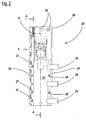
- a hidden hanging bracket is indicated as a whole with 20 and is structurally composed of a metallic base 21 having an elongated rectangular form.
- Two mechanisms 22, 23 for respectively regulating the height and depth of the cupboard mounted on a wall, are assembled on said base 21.
- the hanging bracket 20 is destined for being fixed to the shoulder S and to the top C of a wall cupboard M, and possibly also to a lining 19.
- the long sides of the base 21 have respective edges 24, 25 provided with fixing means of the hanging bracket to the respective shoulder of the wall cupboard.
- said fixing means consist of pins 26, extending from the edge 24, and from holes 27 - for the passage of self-threading screws (not shown) - formed through the edge 25.
- Holes 28 for the passage of self-threading screws (not shown) for additionally fixing the hanging bracket 20 to the shoulder S are also formed in the edge 24, between said pins 26.
- a hidden hanging bracket 20 structured as described and illustrated above, is either right or left, i.e. it can be fixed to the right shoulder or to the left shoulder of the wall cupboard using either pins or screws.
- a tilted flange 29 provided with holes 30 for the passage of tilted self-threading screws 31, extends from the upper end of the base 21 for fixing the hanging bracket 20 also to the top C of the wall cupboard M.
- At least one screw 31 (one or more screws 31) is pre-assembled directly in the respective hole 30, i.e. without the intervention of further elements applied to the flange 29, through which (additional elements) said screw 31 is screwed (according to the known art).
- one or more of said holes 30 comprise a bush 32 integrally formed from the flange 29 by means of drawing.
- the tip of the screw 31 is screwed through said bush 32 (pointed), with interference, so that it is pre-assembled on the hanging bracket.
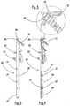
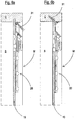
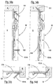
- FIGS 7-14 of the drawings show a second possible embodiment of the invention in which the same and/or equivalent components to those illustrated in figures 1-6 are indicated with the same reference numbers increased by 100.
- one or more of the holes 128 also comprise a bush 132 for the passage of a screw 131, when the hanging bracket 120 is to be fixed to the shoulder S, not only by means of the pins 126, but also by means of one or more self-threading screws 131A ( figures 14 , 14a,14b,14c,14d ).
- FIG. 15 of the drawings illustrates a third possible embodiment of the invention in which the same and/or equivalent components to those illustrated in figures 1-6 are indicated with the same reference numbers increased by 200.
- the hidden hanging bracket 220 comprises a pair of screws 231 pre-assembled at the opposite ends of the flange 230 and screws 231A and 231B pre-assembled on the edges 224 and 225 respectively of the base 221.
- the fitter unscrews (removes) the screws 231B, and possibly also the screw 231A and the corresponding screw 231, if pins 226 are used for fixing the hanging bracket 220 to the shoulder S of the wall cupboard.
- the screws 231B are used for fixing the hanging bracket 220 to the shoulder S, the screw 231A and possibly also the corresponding screw 231 will be unscrewed (removed).
- Figure 16 of the drawings illustrates a fourth possible embodiment of the invention in which the same and/or equivalent components to those illustrated in figures 1-6 are indicated with the same reference numbers increased by 300.
- the hidden hanging bracket illustrated in figure 16 comprises a pair of screws 331 pre-assembled at the opposite ends of the flange 330 and screws 331A and 331B pre-assembled on the edges 324 and 325 respectively of the base 321.
- the hanging bracket 320 illustrated is either right or left, using only fixing screws, and not pins on one side and screws on the opposite side, as in the embodiment described above.
- the fitter eliminates the screw 331A, or the screw 331B, i.e. that which is not necessary, and possibly also the corresponding screw 331, on the flange 330.
- FIG. 17 of the drawings illustrates a fifth possible embodiment of the invention in which the same and/or equivalent components to those illustrated in figures 1-6 are indicated with the same reference numbers increased by 400.
- the hidden hanging bracket illustrated in figure 17 comprises a pair of screws 431 pre-assembled at the opposite ends of the flange 430 and screws 431A and 431B pre-assembled on the edges 424 and 425 respectively of the base 421.
- the hanging bracket illustrated is either right or left, using pins 426 and screws 431A and 431B for fixing it to the shoulder S on both sides 424 and 425.
- the fitter eliminates the screw 431A, or the screw 431B, i.e. that which is not necessary, and possibly also the corresponding screw 431, on the flange 430.
Landscapes
- Connection Of Plates (AREA)
- Casings For Electric Apparatus (AREA)
- Furniture Connections (AREA)
Applications Claiming Priority (1)
| Application Number | Priority Date | Filing Date | Title |
|---|---|---|---|
| ITMI20150039 | 2015-01-19 |
Publications (1)
| Publication Number | Publication Date |
|---|---|
| EP3045077A1 true EP3045077A1 (de) | 2016-07-20 |
Family
ID=52682813
Family Applications (1)
| Application Number | Title | Priority Date | Filing Date |
|---|---|---|---|
| EP16151235.5A Ceased EP3045077A1 (de) | 2015-01-19 | 2016-01-14 | Versteckter aufhängebeschlag mit vormontierten schrauben zur befestigung an einem wandschrank |
Country Status (3)
| Country | Link |
|---|---|
| EP (1) | EP3045077A1 (de) |
| DE (1) | DE202016008564U1 (de) |
| ES (1) | ES1223704Y (de) |
Citations (2)
| Publication number | Priority date | Publication date | Assignee | Title |
|---|---|---|---|---|
| EP0555924A1 (de) * | 1992-02-14 | 1993-08-18 | CAMAR S.p.A. | Verbesserte verborgene Vorrichtung zur Wandmontage eines Wandmöbelelementes |
| DE20318237U1 (de) * | 2002-12-06 | 2004-02-12 | Julius Blum Ges.M.B.H. | Scharnier |
-
2016
- 2016-01-14 DE DE202016008564.7U patent/DE202016008564U1/de not_active Expired - Lifetime
- 2016-01-14 EP EP16151235.5A patent/EP3045077A1/de not_active Ceased
- 2016-01-14 ES ES201831514U patent/ES1223704Y/es not_active Expired - Fee Related
Patent Citations (2)
| Publication number | Priority date | Publication date | Assignee | Title |
|---|---|---|---|---|
| EP0555924A1 (de) * | 1992-02-14 | 1993-08-18 | CAMAR S.p.A. | Verbesserte verborgene Vorrichtung zur Wandmontage eines Wandmöbelelementes |
| DE20318237U1 (de) * | 2002-12-06 | 2004-02-12 | Julius Blum Ges.M.B.H. | Scharnier |
Also Published As
| Publication number | Publication date |
|---|---|
| DE202016008564U1 (de) | 2018-06-14 |
| ES1223704U (es) | 2019-01-25 |
| ES1223704Y (es) | 2019-04-17 |
Similar Documents
| Publication | Publication Date | Title |
|---|---|---|
| AU2014210119B2 (en) | An induction module for an induction cooking hob | |
| DE102005057160A1 (de) | Gehäuse für ein Haushaltsgerät | |
| EP2703731B1 (de) | Lagerbuchse für ein Haushaltsgerät mit einem pilzförmigen Basiskörper mit einem frontseitig zugänglichen Hohlraum sowie Haushaltsgerät | |
| DE102015221885A1 (de) | Tür mit einem Türrahmen und einem Griffmuldenelement sowie Haushaltskältegerät mit einer derartigen Tür | |
| DE102016118267A1 (de) | Haltewinkel, Befestigungssystem und Haushaltsgerät | |
| KR20140026546A (ko) | 서랍 | |
| EP3168483A1 (de) | Schubladenteilanordnung und montagebeschlag davon | |
| DE102012217358A1 (de) | Lagerbuchse, welche zum Lagern eines Haushaltsgerätebauteils an einer Haushaltsgerätekomponente ausgebildet ist, sowie Haushaltsgerät mit einer derartigen Lagerbuchse | |
| DE102011050987A1 (de) | Schnellbefestigungselement | |
| DE102010041950A1 (de) | Kältegerät mit einem Fachboden | |
| CN104352087B (zh) | 新型可变组合办公桌 | |
| DE102011007410A1 (de) | Einbau-Kältegrät mit einem Beschlagsbauteil | |
| EP2290308A2 (de) | Kältegerät | |
| DE102010041935A1 (de) | Gargerät | |
| EP3369341B1 (de) | Wandelement für eine zarge einer schublade | |
| DE102013205747B4 (de) | Einbau übereinander angeordneter Haushaltsgeräte in ein Möbel | |
| EP2844108A1 (de) | Haltevorrichtung für ein tragelement eines schrankes sowie kühl-, gefrierschrank oder weinlagerungsschrank | |
| WO2012028546A3 (en) | Guide rail and frame assembly, shelf pan and refrigerator | |
| EP3155935B1 (de) | Regalsystem zur warenpräsentation bestehend aus einer einsteckvorrichtung | |
| KR101229561B1 (ko) | 책상 | |
| EP2827067A2 (de) | Zentralrahmen für Dunstabzugshaube und Dunstabzugshaube | |
| EP3167758B1 (de) | Schubladenseitenwand | |
| EP3086065B1 (de) | Haushaltskältegerät mit einem lagerwinkel mit plattenförmigem auflagedach | |
| DE102015212283A1 (de) | Lüftergehäuse für eine Dunstabzugshaube | |
| EP2947232A1 (de) | Hängende klammern mit vertikaler regulierungsvorrichtung zur wandmontage von deckplatten |
Legal Events
| Date | Code | Title | Description |
|---|---|---|---|
| PUAI | Public reference made under article 153(3) epc to a published international application that has entered the european phase |
Free format text: ORIGINAL CODE: 0009012 |
|
| AK | Designated contracting states |
Kind code of ref document: A1 Designated state(s): AL AT BE BG CH CY CZ DE DK EE ES FI FR GB GR HR HU IE IS IT LI LT LU LV MC MK MT NL NO PL PT RO RS SE SI SK SM TR |
|
| AX | Request for extension of the european patent |
Extension state: BA ME |
|
| STAA | Information on the status of an ep patent application or granted ep patent |
Free format text: STATUS: REQUEST FOR EXAMINATION WAS MADE |
|
| 17P | Request for examination filed |
Effective date: 20170116 |
|
| RBV | Designated contracting states (corrected) |
Designated state(s): AL AT BE BG CH CY CZ DE DK EE ES FI FR GB GR HR HU IE IS IT LI LT LU LV MC MK MT NL NO PL PT RO RS SE SI SK SM TR |
|
| STAA | Information on the status of an ep patent application or granted ep patent |
Free format text: STATUS: EXAMINATION IS IN PROGRESS |
|
| 17Q | First examination report despatched |
Effective date: 20170309 |
|
| STAA | Information on the status of an ep patent application or granted ep patent |
Free format text: STATUS: THE APPLICATION HAS BEEN REFUSED |
|
| 18R | Application refused |
Effective date: 20180527 |
|
| 110E | Request filed for conversion into a national patent application [according to art. 135 epc] |
Effective date: 20180725 |