EP3045220B1 - Abgasbehandlungsverfahren und denitrifikations-/so3-reduktionsvorrichtung - Google Patents
Abgasbehandlungsverfahren und denitrifikations-/so3-reduktionsvorrichtung Download PDFInfo
- Publication number
- EP3045220B1 EP3045220B1 EP15783949.9A EP15783949A EP3045220B1 EP 3045220 B1 EP3045220 B1 EP 3045220B1 EP 15783949 A EP15783949 A EP 15783949A EP 3045220 B1 EP3045220 B1 EP 3045220B1
- Authority
- EP
- European Patent Office
- Prior art keywords
- flue gas
- catalyst
- catalyst layer
- denitration
- injection device
- Prior art date
- Legal status (The legal status is an assumption and is not a legal conclusion. Google has not performed a legal analysis and makes no representation as to the accuracy of the status listed.)
- Active
Links
Images


Classifications
-
- B—PERFORMING OPERATIONS; TRANSPORTING
- B01—PHYSICAL OR CHEMICAL PROCESSES OR APPARATUS IN GENERAL
- B01D—SEPARATION
- B01D53/00—Separation of gases or vapours; Recovering vapours of volatile solvents from gases; Chemical or biological purification of waste gases, e.g. engine exhaust gases, smoke, fumes, flue gases, aerosols
- B01D53/34—Chemical or biological purification of waste gases
- B01D53/46—Removing components of defined structure
- B01D53/48—Sulfur compounds
- B01D53/50—Sulfur oxides
-
- B—PERFORMING OPERATIONS; TRANSPORTING
- B01—PHYSICAL OR CHEMICAL PROCESSES OR APPARATUS IN GENERAL
- B01D—SEPARATION
- B01D53/00—Separation of gases or vapours; Recovering vapours of volatile solvents from gases; Chemical or biological purification of waste gases, e.g. engine exhaust gases, smoke, fumes, flue gases, aerosols
- B01D53/34—Chemical or biological purification of waste gases
- B01D53/46—Removing components of defined structure
- B01D53/60—Simultaneously removing sulfur oxides and nitrogen oxides
-
- B—PERFORMING OPERATIONS; TRANSPORTING
- B01—PHYSICAL OR CHEMICAL PROCESSES OR APPARATUS IN GENERAL
- B01D—SEPARATION
- B01D53/00—Separation of gases or vapours; Recovering vapours of volatile solvents from gases; Chemical or biological purification of waste gases, e.g. engine exhaust gases, smoke, fumes, flue gases, aerosols
- B01D53/34—Chemical or biological purification of waste gases
- B01D53/74—General processes for purification of waste gases; Apparatus or devices specially adapted therefor
- B01D53/86—Catalytic processes
- B01D53/8603—Removing sulfur compounds
- B01D53/8609—Sulfur oxides
-
- B—PERFORMING OPERATIONS; TRANSPORTING
- B01—PHYSICAL OR CHEMICAL PROCESSES OR APPARATUS IN GENERAL
- B01D—SEPARATION
- B01D53/00—Separation of gases or vapours; Recovering vapours of volatile solvents from gases; Chemical or biological purification of waste gases, e.g. engine exhaust gases, smoke, fumes, flue gases, aerosols
- B01D53/34—Chemical or biological purification of waste gases
- B01D53/74—General processes for purification of waste gases; Apparatus or devices specially adapted therefor
- B01D53/86—Catalytic processes
- B01D53/8621—Removing nitrogen compounds
- B01D53/8625—Nitrogen oxides
- B01D53/8628—Processes characterised by a specific catalyst
-
- B—PERFORMING OPERATIONS; TRANSPORTING
- B01—PHYSICAL OR CHEMICAL PROCESSES OR APPARATUS IN GENERAL
- B01D—SEPARATION
- B01D53/00—Separation of gases or vapours; Recovering vapours of volatile solvents from gases; Chemical or biological purification of waste gases, e.g. engine exhaust gases, smoke, fumes, flue gases, aerosols
- B01D53/34—Chemical or biological purification of waste gases
- B01D53/74—General processes for purification of waste gases; Apparatus or devices specially adapted therefor
- B01D53/86—Catalytic processes
- B01D53/8637—Simultaneously removing sulfur oxides and nitrogen oxides
-
- B—PERFORMING OPERATIONS; TRANSPORTING
- B01—PHYSICAL OR CHEMICAL PROCESSES OR APPARATUS IN GENERAL
- B01D—SEPARATION
- B01D53/00—Separation of gases or vapours; Recovering vapours of volatile solvents from gases; Chemical or biological purification of waste gases, e.g. engine exhaust gases, smoke, fumes, flue gases, aerosols
- B01D53/34—Chemical or biological purification of waste gases
- B01D53/74—General processes for purification of waste gases; Apparatus or devices specially adapted therefor
- B01D53/86—Catalytic processes
- B01D53/90—Injecting reactants
-
- B—PERFORMING OPERATIONS; TRANSPORTING
- B01—PHYSICAL OR CHEMICAL PROCESSES OR APPARATUS IN GENERAL
- B01J—CHEMICAL OR PHYSICAL PROCESSES, e.g. CATALYSIS OR COLLOID CHEMISTRY; THEIR RELEVANT APPARATUS
- B01J21/00—Catalysts comprising the elements, oxides, or hydroxides of magnesium, boron, aluminium, carbon, silicon, titanium, zirconium, or hafnium
- B01J21/06—Silicon, titanium, zirconium or hafnium; Oxides or hydroxides thereof
- B01J21/063—Titanium; Oxides or hydroxides thereof
-
- B—PERFORMING OPERATIONS; TRANSPORTING
- B01—PHYSICAL OR CHEMICAL PROCESSES OR APPARATUS IN GENERAL
- B01J—CHEMICAL OR PHYSICAL PROCESSES, e.g. CATALYSIS OR COLLOID CHEMISTRY; THEIR RELEVANT APPARATUS
- B01J21/00—Catalysts comprising the elements, oxides, or hydroxides of magnesium, boron, aluminium, carbon, silicon, titanium, zirconium, or hafnium
- B01J21/06—Silicon, titanium, zirconium or hafnium; Oxides or hydroxides thereof
- B01J21/066—Zirconium or hafnium; Oxides or hydroxides thereof
-
- B—PERFORMING OPERATIONS; TRANSPORTING
- B01—PHYSICAL OR CHEMICAL PROCESSES OR APPARATUS IN GENERAL
- B01J—CHEMICAL OR PHYSICAL PROCESSES, e.g. CATALYSIS OR COLLOID CHEMISTRY; THEIR RELEVANT APPARATUS
- B01J23/00—Catalysts comprising metals or metal oxides or hydroxides, not provided for in group B01J21/00
- B01J23/10—Catalysts comprising metals or metal oxides or hydroxides, not provided for in group B01J21/00 of rare earths
-
- B—PERFORMING OPERATIONS; TRANSPORTING
- B01—PHYSICAL OR CHEMICAL PROCESSES OR APPARATUS IN GENERAL
- B01J—CHEMICAL OR PHYSICAL PROCESSES, e.g. CATALYSIS OR COLLOID CHEMISTRY; THEIR RELEVANT APPARATUS
- B01J23/00—Catalysts comprising metals or metal oxides or hydroxides, not provided for in group B01J21/00
- B01J23/16—Catalysts comprising metals or metal oxides or hydroxides, not provided for in group B01J21/00 of arsenic, antimony, bismuth, vanadium, niobium, tantalum, polonium, chromium, molybdenum, tungsten, manganese, technetium or rhenium
- B01J23/20—Vanadium, niobium or tantalum
- B01J23/22—Vanadium
-
- B—PERFORMING OPERATIONS; TRANSPORTING
- B01—PHYSICAL OR CHEMICAL PROCESSES OR APPARATUS IN GENERAL
- B01J—CHEMICAL OR PHYSICAL PROCESSES, e.g. CATALYSIS OR COLLOID CHEMISTRY; THEIR RELEVANT APPARATUS
- B01J23/00—Catalysts comprising metals or metal oxides or hydroxides, not provided for in group B01J21/00
- B01J23/16—Catalysts comprising metals or metal oxides or hydroxides, not provided for in group B01J21/00 of arsenic, antimony, bismuth, vanadium, niobium, tantalum, polonium, chromium, molybdenum, tungsten, manganese, technetium or rhenium
- B01J23/24—Chromium, molybdenum or tungsten
- B01J23/28—Molybdenum
-
- B—PERFORMING OPERATIONS; TRANSPORTING
- B01—PHYSICAL OR CHEMICAL PROCESSES OR APPARATUS IN GENERAL
- B01J—CHEMICAL OR PHYSICAL PROCESSES, e.g. CATALYSIS OR COLLOID CHEMISTRY; THEIR RELEVANT APPARATUS
- B01J23/00—Catalysts comprising metals or metal oxides or hydroxides, not provided for in group B01J21/00
- B01J23/16—Catalysts comprising metals or metal oxides or hydroxides, not provided for in group B01J21/00 of arsenic, antimony, bismuth, vanadium, niobium, tantalum, polonium, chromium, molybdenum, tungsten, manganese, technetium or rhenium
- B01J23/24—Chromium, molybdenum or tungsten
- B01J23/30—Tungsten
-
- B—PERFORMING OPERATIONS; TRANSPORTING
- B01—PHYSICAL OR CHEMICAL PROCESSES OR APPARATUS IN GENERAL
- B01J—CHEMICAL OR PHYSICAL PROCESSES, e.g. CATALYSIS OR COLLOID CHEMISTRY; THEIR RELEVANT APPARATUS
- B01J23/00—Catalysts comprising metals or metal oxides or hydroxides, not provided for in group B01J21/00
- B01J23/16—Catalysts comprising metals or metal oxides or hydroxides, not provided for in group B01J21/00 of arsenic, antimony, bismuth, vanadium, niobium, tantalum, polonium, chromium, molybdenum, tungsten, manganese, technetium or rhenium
- B01J23/32—Manganese, technetium or rhenium
- B01J23/34—Manganese
-
- B—PERFORMING OPERATIONS; TRANSPORTING
- B01—PHYSICAL OR CHEMICAL PROCESSES OR APPARATUS IN GENERAL
- B01J—CHEMICAL OR PHYSICAL PROCESSES, e.g. CATALYSIS OR COLLOID CHEMISTRY; THEIR RELEVANT APPARATUS
- B01J23/00—Catalysts comprising metals or metal oxides or hydroxides, not provided for in group B01J21/00
- B01J23/38—Catalysts comprising metals or metal oxides or hydroxides, not provided for in group B01J21/00 of noble metals
- B01J23/54—Catalysts comprising metals or metal oxides or hydroxides, not provided for in group B01J21/00 of noble metals combined with metals, oxides or hydroxides provided for in groups B01J23/02 - B01J23/36
- B01J23/56—Platinum group metals
- B01J23/64—Platinum group metals with arsenic, antimony, bismuth, vanadium, niobium, tantalum, polonium, chromium, molybdenum, tungsten, manganese, technetium or rhenium
- B01J23/652—Chromium, molybdenum or tungsten
- B01J23/6527—Tungsten
-
- B—PERFORMING OPERATIONS; TRANSPORTING
- B01—PHYSICAL OR CHEMICAL PROCESSES OR APPARATUS IN GENERAL
- B01J—CHEMICAL OR PHYSICAL PROCESSES, e.g. CATALYSIS OR COLLOID CHEMISTRY; THEIR RELEVANT APPARATUS
- B01J23/00—Catalysts comprising metals or metal oxides or hydroxides, not provided for in group B01J21/00
- B01J23/70—Catalysts comprising metals or metal oxides or hydroxides, not provided for in group B01J21/00 of the iron group metals or copper
- B01J23/74—Iron group metals
- B01J23/75—Cobalt
-
- B—PERFORMING OPERATIONS; TRANSPORTING
- B01—PHYSICAL OR CHEMICAL PROCESSES OR APPARATUS IN GENERAL
- B01J—CHEMICAL OR PHYSICAL PROCESSES, e.g. CATALYSIS OR COLLOID CHEMISTRY; THEIR RELEVANT APPARATUS
- B01J23/00—Catalysts comprising metals or metal oxides or hydroxides, not provided for in group B01J21/00
- B01J23/70—Catalysts comprising metals or metal oxides or hydroxides, not provided for in group B01J21/00 of the iron group metals or copper
- B01J23/74—Iron group metals
- B01J23/755—Nickel
-
- B—PERFORMING OPERATIONS; TRANSPORTING
- B01—PHYSICAL OR CHEMICAL PROCESSES OR APPARATUS IN GENERAL
- B01J—CHEMICAL OR PHYSICAL PROCESSES, e.g. CATALYSIS OR COLLOID CHEMISTRY; THEIR RELEVANT APPARATUS
- B01J29/00—Catalysts comprising molecular sieves
- B01J29/04—Catalysts comprising molecular sieves having base-exchange properties, e.g. crystalline zeolites
- B01J29/06—Crystalline aluminosilicate zeolites; Isomorphous compounds thereof
- B01J29/076—Crystalline aluminosilicate zeolites; Isomorphous compounds thereof containing arsenic, antimony, bismuth, vanadium, niobium, tantalum, polonium, chromium, molybdenum, tungsten, manganese, technetium or rhenium
-
- B—PERFORMING OPERATIONS; TRANSPORTING
- B01—PHYSICAL OR CHEMICAL PROCESSES OR APPARATUS IN GENERAL
- B01J—CHEMICAL OR PHYSICAL PROCESSES, e.g. CATALYSIS OR COLLOID CHEMISTRY; THEIR RELEVANT APPARATUS
- B01J35/00—Catalysts, in general, characterised by their form or physical properties
- B01J35/50—Catalysts, in general, characterised by their form or physical properties characterised by their shape or configuration
- B01J35/56—Foraminous structures having flow-through passages or channels, e.g. grids or three-dimensional [3D] monoliths
- B01J35/57—Honeycombs
-
- B—PERFORMING OPERATIONS; TRANSPORTING
- B01—PHYSICAL OR CHEMICAL PROCESSES OR APPARATUS IN GENERAL
- B01J—CHEMICAL OR PHYSICAL PROCESSES, e.g. CATALYSIS OR COLLOID CHEMISTRY; THEIR RELEVANT APPARATUS
- B01J37/00—Processes, in general, for preparing catalysts; Processes, in general, for activation of catalysts
- B01J37/02—Impregnation, coating or precipitation
- B01J37/0215—Coating
-
- B—PERFORMING OPERATIONS; TRANSPORTING
- B01—PHYSICAL OR CHEMICAL PROCESSES OR APPARATUS IN GENERAL
- B01J—CHEMICAL OR PHYSICAL PROCESSES, e.g. CATALYSIS OR COLLOID CHEMISTRY; THEIR RELEVANT APPARATUS
- B01J37/00—Processes, in general, for preparing catalysts; Processes, in general, for activation of catalysts
- B01J37/02—Impregnation, coating or precipitation
- B01J37/024—Multiple impregnation or coating
- B01J37/0248—Coatings comprising impregnated particles
-
- B—PERFORMING OPERATIONS; TRANSPORTING
- B01—PHYSICAL OR CHEMICAL PROCESSES OR APPARATUS IN GENERAL
- B01J—CHEMICAL OR PHYSICAL PROCESSES, e.g. CATALYSIS OR COLLOID CHEMISTRY; THEIR RELEVANT APPARATUS
- B01J37/00—Processes, in general, for preparing catalysts; Processes, in general, for activation of catalysts
- B01J37/08—Heat treatment
-
- B—PERFORMING OPERATIONS; TRANSPORTING
- B01—PHYSICAL OR CHEMICAL PROCESSES OR APPARATUS IN GENERAL
- B01D—SEPARATION
- B01D2251/00—Reactants
- B01D2251/20—Reductants
- B01D2251/206—Ammonium compounds
- B01D2251/2062—Ammonia
-
- B—PERFORMING OPERATIONS; TRANSPORTING
- B01—PHYSICAL OR CHEMICAL PROCESSES OR APPARATUS IN GENERAL
- B01D—SEPARATION
- B01D2251/00—Reactants
- B01D2251/20—Reductants
- B01D2251/208—Hydrocarbons
-
- B—PERFORMING OPERATIONS; TRANSPORTING
- B01—PHYSICAL OR CHEMICAL PROCESSES OR APPARATUS IN GENERAL
- B01D—SEPARATION
- B01D2255/00—Catalysts
- B01D2255/10—Noble metals or compounds thereof
- B01D2255/102—Platinum group metals
- B01D2255/1026—Ruthenium
-
- B—PERFORMING OPERATIONS; TRANSPORTING
- B01—PHYSICAL OR CHEMICAL PROCESSES OR APPARATUS IN GENERAL
- B01D—SEPARATION
- B01D2255/00—Catalysts
- B01D2255/20—Metals or compounds thereof
- B01D2255/206—Rare earth metals
- B01D2255/2065—Cerium
-
- B—PERFORMING OPERATIONS; TRANSPORTING
- B01—PHYSICAL OR CHEMICAL PROCESSES OR APPARATUS IN GENERAL
- B01D—SEPARATION
- B01D2255/00—Catalysts
- B01D2255/20—Metals or compounds thereof
- B01D2255/207—Transition metals
- B01D2255/20707—Titanium
-
- B—PERFORMING OPERATIONS; TRANSPORTING
- B01—PHYSICAL OR CHEMICAL PROCESSES OR APPARATUS IN GENERAL
- B01D—SEPARATION
- B01D2255/00—Catalysts
- B01D2255/20—Metals or compounds thereof
- B01D2255/207—Transition metals
- B01D2255/20715—Zirconium
-
- B—PERFORMING OPERATIONS; TRANSPORTING
- B01—PHYSICAL OR CHEMICAL PROCESSES OR APPARATUS IN GENERAL
- B01D—SEPARATION
- B01D2255/00—Catalysts
- B01D2255/20—Metals or compounds thereof
- B01D2255/207—Transition metals
- B01D2255/20723—Vanadium
-
- B—PERFORMING OPERATIONS; TRANSPORTING
- B01—PHYSICAL OR CHEMICAL PROCESSES OR APPARATUS IN GENERAL
- B01D—SEPARATION
- B01D2255/00—Catalysts
- B01D2255/20—Metals or compounds thereof
- B01D2255/207—Transition metals
- B01D2255/2073—Manganese
-
- B—PERFORMING OPERATIONS; TRANSPORTING
- B01—PHYSICAL OR CHEMICAL PROCESSES OR APPARATUS IN GENERAL
- B01D—SEPARATION
- B01D2255/00—Catalysts
- B01D2255/20—Metals or compounds thereof
- B01D2255/207—Transition metals
- B01D2255/20746—Cobalt
-
- B—PERFORMING OPERATIONS; TRANSPORTING
- B01—PHYSICAL OR CHEMICAL PROCESSES OR APPARATUS IN GENERAL
- B01D—SEPARATION
- B01D2255/00—Catalysts
- B01D2255/20—Metals or compounds thereof
- B01D2255/207—Transition metals
- B01D2255/20753—Nickel
-
- B—PERFORMING OPERATIONS; TRANSPORTING
- B01—PHYSICAL OR CHEMICAL PROCESSES OR APPARATUS IN GENERAL
- B01D—SEPARATION
- B01D2255/00—Catalysts
- B01D2255/20—Metals or compounds thereof
- B01D2255/207—Transition metals
- B01D2255/20769—Molybdenum
-
- B—PERFORMING OPERATIONS; TRANSPORTING
- B01—PHYSICAL OR CHEMICAL PROCESSES OR APPARATUS IN GENERAL
- B01D—SEPARATION
- B01D2255/00—Catalysts
- B01D2255/20—Metals or compounds thereof
- B01D2255/207—Transition metals
- B01D2255/20776—Tungsten
-
- B—PERFORMING OPERATIONS; TRANSPORTING
- B01—PHYSICAL OR CHEMICAL PROCESSES OR APPARATUS IN GENERAL
- B01D—SEPARATION
- B01D2255/00—Catalysts
- B01D2255/30—Silica
-
- B—PERFORMING OPERATIONS; TRANSPORTING
- B01—PHYSICAL OR CHEMICAL PROCESSES OR APPARATUS IN GENERAL
- B01D—SEPARATION
- B01D2255/00—Catalysts
- B01D2255/40—Mixed oxides
-
- B—PERFORMING OPERATIONS; TRANSPORTING
- B01—PHYSICAL OR CHEMICAL PROCESSES OR APPARATUS IN GENERAL
- B01D—SEPARATION
- B01D2257/00—Components to be removed
- B01D2257/30—Sulfur compounds
- B01D2257/302—Sulfur oxides
-
- B—PERFORMING OPERATIONS; TRANSPORTING
- B01—PHYSICAL OR CHEMICAL PROCESSES OR APPARATUS IN GENERAL
- B01D—SEPARATION
- B01D2257/00—Components to be removed
- B01D2257/40—Nitrogen compounds
- B01D2257/404—Nitrogen oxides other than dinitrogen oxide
-
- B—PERFORMING OPERATIONS; TRANSPORTING
- B01—PHYSICAL OR CHEMICAL PROCESSES OR APPARATUS IN GENERAL
- B01D—SEPARATION
- B01D2258/00—Sources of waste gases
- B01D2258/02—Other waste gases
- B01D2258/0283—Flue gases
-
- B—PERFORMING OPERATIONS; TRANSPORTING
- B01—PHYSICAL OR CHEMICAL PROCESSES OR APPARATUS IN GENERAL
- B01J—CHEMICAL OR PHYSICAL PROCESSES, e.g. CATALYSIS OR COLLOID CHEMISTRY; THEIR RELEVANT APPARATUS
- B01J23/00—Catalysts comprising metals or metal oxides or hydroxides, not provided for in group B01J21/00
- B01J23/38—Catalysts comprising metals or metal oxides or hydroxides, not provided for in group B01J21/00 of noble metals
- B01J23/40—Catalysts comprising metals or metal oxides or hydroxides, not provided for in group B01J21/00 of noble metals of the platinum group metals
- B01J23/46—Ruthenium, rhodium, osmium or iridium
- B01J23/462—Ruthenium
-
- B—PERFORMING OPERATIONS; TRANSPORTING
- B01—PHYSICAL OR CHEMICAL PROCESSES OR APPARATUS IN GENERAL
- B01J—CHEMICAL OR PHYSICAL PROCESSES, e.g. CATALYSIS OR COLLOID CHEMISTRY; THEIR RELEVANT APPARATUS
- B01J23/00—Catalysts comprising metals or metal oxides or hydroxides, not provided for in group B01J21/00
- B01J23/38—Catalysts comprising metals or metal oxides or hydroxides, not provided for in group B01J21/00 of noble metals
- B01J23/54—Catalysts comprising metals or metal oxides or hydroxides, not provided for in group B01J21/00 of noble metals combined with metals, oxides or hydroxides provided for in groups B01J23/02 - B01J23/36
- B01J23/56—Platinum group metals
- B01J23/63—Platinum group metals with rare earths or actinides
-
- Y—GENERAL TAGGING OF NEW TECHNOLOGICAL DEVELOPMENTS; GENERAL TAGGING OF CROSS-SECTIONAL TECHNOLOGIES SPANNING OVER SEVERAL SECTIONS OF THE IPC; TECHNICAL SUBJECTS COVERED BY FORMER USPC CROSS-REFERENCE ART COLLECTIONS [XRACs] AND DIGESTS
- Y02—TECHNOLOGIES OR APPLICATIONS FOR MITIGATION OR ADAPTATION AGAINST CLIMATE CHANGE
- Y02A—TECHNOLOGIES FOR ADAPTATION TO CLIMATE CHANGE
- Y02A50/00—TECHNOLOGIES FOR ADAPTATION TO CLIMATE CHANGE in human health protection, e.g. against extreme weather
- Y02A50/20—Air quality improvement or preservation, e.g. vehicle emission control or emission reduction by using catalytic converters
Definitions
- the present invention relates to a flue gas treatment method and to a denitration and SO 3 reduction apparatus, and more specifically relates to a flue gas treatment method and to a denitration and SO 3 reduction apparatus for treatment of a combustion flue gas including sulfur trioxide.
- SO x sulfur trioxide (SO 3 ) is corrosive, and is a factor that inhibits the continuous long-term operation for treating flue gases due to clogging by ash inside flue gas treatment facilities such as an air preheater and an electric precipitator, dew point corrosion, and the like caused due to SO 3 .
- Patent Literature 3 discloses a system and a method for removing nitrogen oxide and sulfur trioxide from exhaust gas using a catalyst, wherein a sulfur trioxide reducing catalyst on the upstream side and a denitration catalyst on the downstream side are arranged in series with respect to the flow direction of exhaust gas.
- the denitration catalyst comprises a carrier containing titania, and at least one metal selected from Mo, W and V supported on said carrier.
- Patent Literature 4 discloses a method for selectively removing nitrogen oxides from exhaust gas, the method comprising contacting the exhaust gas with ammonia in the presence of a catalyst which comprises 30 to 99% by weight of at least one catalytic oxide selected from a binary oxide comprising titanium and silicon and a ternary oxide comprising Ti, Zr and Si, and 1 to 70% by weight of a catalytic oxide comprising at least one element selected from the group consisting of V, W, Mo, U, Cu, Fe, Cr, Mn and Ce.
- Patent Literature 5 discloses a method for removing arsenic compounds adsorbed on a denitration catalyst, the method comprising heat-treating the denitration catalyst in a reducing atmosphere while exposing the catalyst to hydrocarbon compounds except for methane and oxygen-containing carbon compounds.
- the denitration catalyst comprises a titanium dioxide carrier, and has a transition metal oxide such as V 2 O 5 , WO 3 or MoO 3 supported thereon as the active component.
- Patent Literature 6 discloses a method for minimizing generation of sulfur trioxide in a gas stream containing oxygen and sulfur dioxide, the method comprising contacting the gas stream with a catalyst comprising a carrier and a catalytically active phase comprising Rh and Pt, wherein the Rh content in the catalytically active phase is ⁇ 25% by weight.
- the method may further comprise contacting the gas stream with an agent effecting reduction of sulfur trioxide to sulfur dioxide, with propylene being mentioned as an example of such agent.
- an object of the present invention is to provide a flue gas treatment method and a denitration and SO 3 reduction apparatus that reduce treatment costs, reduce NO x contained in a combustion flue gas, and reduce the concentration of SO 3 more efficiently compared with prior art.
- the present invention thus relates to a flue gas treatment method in which a 3C-5C olefinic hydrocarbon (unsaturated hydrocarbon) is added to a combustion flue gas including SO 3 as well as NO x as a first additive, and then the combustion flue gas is brought into contact with a catalyst which includes an oxide constituted by one or more of elements selected from the group consisting of Ti, Si, Zr, and Ce and/or a mixed oxide and/or a complex oxide constituted by two or more of elements selected from the group as a carrier but not including a noble metal, and thereby SO 3 is treated by reduction to SO 2 .
- a catalyst which includes an oxide constituted by one or more of elements selected from the group consisting of Ti, Si, Zr, and Ce and/or a mixed oxide and/or a complex oxide constituted by two or more of elements selected from the group as a carrier but not including a noble metal, and thereby SO 3 is treated by reduction to SO 2 .
- the 3C-5C olefinic hydrocarbon (unsaturated hydrocarbon) be one or more selected from the group consisting of C 3 H 6 , C 4 H 8 , and C 5 H 10 .
- the C 4 H 8 and C 5 H 10 may be a geometric isomer or a racemic body of either one thereof.
- the carrier include a mixed oxide and/or a complex oxide including one or more selected from the group consisting of TiO 2 -SiO 2 , TiO 2 -ZrO 2 , and TiO 2 -CeO 2 .
- the performance of reduction of SO 3 into SO 2 can be dramatically improved by using a mixed oxide and/or complex oxide with TiO 2 and with an amount of solid acid higher than a predetermined value.
- the catalyst may be a catalyst in which a metal oxide including one or more selected from the group consisting of V 2 O 5 , WO 3 , MoO 3 , Mn 2 O 3 , MnO 2 , NiO, and Co 3 O 4 is carried on the complex oxide as the carrier.
- a metallosilicate-base complex oxide in which at least a part of A1 and/or Si in a zeolite crystal structure is substituted with one or more selected from the group consisting of Ti, V, Mn, Fe, and Co may be coated onto the catalyst.
- NH 3 be added as a second additive simultaneously as the first additive is added and simultaneously perform the reduction of S03 and the denitration when performing a treatment for reducing SO 3 to SO 2 .
- the first additive can be added by partially reforming the ammonia supply line equipment provided to the existing denitration apparatus to contribute to reduction of SO 3 in the combustion flue gas.
- the treatment for reducing SO 3 into SO 2 be performed in a temperature range of 250°C to 450°C. In addition, it is preferable that the treatment for reducing SO 3 into SO 2 be performed in a temperature range of 300°C to 400°C.
- the treatment for reducing SO 3 in the combustion flue gas to SO 2 by using an existing denitration apparatus and under denitration treatment conditions for a high activity of the catalyst as a denitration catalyst.
- the present invention relates to an SO 3 reduction apparatus for performing denitration of NO x and reduction of SO 3 in a combustion flue gas including NO x and SO 3 , the SO 3 reduction apparatus including a first injection device that is configured for adding a 3C-5C olefinic hydrocarbon (unsaturated hydrocarbon) to the combustion flue gas; a second injection device that is arranged close to the first injection device and that is configured for adding NH 3 to the combustion flue gas; and a catalyst layer including a catalyst through which the combustion flue gas is allowed to flow.
- the SO 3 reduction apparatus is configured for simultaneously performing denitration of NO X and reduction of SO 3 into SO 2 in the combustion flue gas, and comprises one of the following configurations (a) and (b):
- a flue gas treatment method and a denitration and SO 3 reduction apparatus are provided which are configured to denitrate NO x in the combustion flue gas and reduce the concentration of SO 3 in the combustion flue gas at the same time at treatment costs lower than those conventionally.
- a denitration and SO 3 reduction apparatus and a flue gas treatment method according to the present invention will be described below with reference to embodiments shown in the attached drawings.
- a flue gas generated by combusting an oil-derived fuel or a coal-derived fuel in a boiler and in an oxygen atmosphere will be herein referred to as a "combustion flue gas”.
- the stream of gas will be herein referred to as a "front stream” or “back stream” in relation to the direction of flow of a combustion flue gas.
- FIG. 1 shows a first embodiment, in which the denitration and SO 3 reduction apparatus according to the present invention is arranged on a back stream side of a boiler.
- a denitration and SO 3 reduction apparatus 5 is arranged on a back stream side of a flue gas chimney 2 of a boiler which generates a flue gas in the furnace 1.
- the boiler burns an externally supplied fuel in the furnace 1 and discharges a combustion flue gas generated by the burning into the flue gas chimney 2.
- the denitration and SO 3 reduction apparatus 5 which is arranged on a back stream side of the flue gas chimney 2, simultaneously performs a NO x denitration treatment and an SO 3 reduction treatment for the combustion flue gas that flows through the flue gas chimney 2.
- the treatment for reducing SO 3 into SO 2 will be referred to as the "SO 3 reduction treatment”.
- An ECO 3 which is arranged in the combustion flue gas chimney 2 in which the combustion flue gas is circulated, performs heat exchange between boiler feed water and the combustion flue gas that flow through the inside of the ECO 3. More specifically, the ECO 3 increases the temperature of the boiler feed water by using the thermal inertia of the combustion flue gas and thereby improves the efficiency of combustion in the boiler.
- An ECO bypass 4 is arranged so that one end thereof is in communication with the front stream side of the ECO 3 and the other end thereof is in communication with the back stream side of the ECO 3, and feeds the combustion flue gas before being fed into the ECO 3 to the side of an inlet of the denitration and SO 3 reduction apparatus 5, bypassing the ECO 3.
- the ECO bypass 4 controls the temperature of the combustion flue gas to be fed into the denitration and SO 3 reduction apparatus 5 within a predetermined temperature range appropriate for denitration and reduction reactions.
- the denitration and SO 3 reduction apparatus 5 is arranged in the combustion flue gas chimney 2, and at least includes a first injection device 6, a second injection device 7, and a catalyst layer 8.
- the denitration and SO 3 reduction apparatus 5 adds a first additive and a second additive to the flue gas and allows the combustion flue gas including the additives to flow through the catalyst layer 8.
- the denitration and SO 3 reduction apparatus 5 performs an SO 3 reduction treatment by using the catalyst layer 8, the first injection device 6, and the second injection device 7. It is preferable that the denitration and SO 3 reduction apparatus 5 be configured so as to add the first additive and the second additive at the same time.
- the first injection device 6 is arranged on a front stream side of the denitration and SO 3 reduction apparatus 5 and on a back stream side of the ECO bypass 4, and adds the first additive to the combustion flue gas including SO 3 as well as NO x . More specifically, the first injection device 6 collaborates with the catalyst layer 8 to reduce SO 3 in the combustion flue gas.
- the first additive injected from the first injection device 6 is an SO 3 reductant primarily for reduction of SO 3 into SO 2 , namely an olefinic hydrocarbon (unsaturated hydrocarbon) expressed by a general formula: C n H 2n (n is an integer of 3 to 5).
- 3C-5C olefinic hydrocarbon unsaturated hydrocarbon
- C 4 H 8 and C 5 H 10 a geometric isomer or a racemic body of either one of them can be used.
- Examples of ⁇ 4C unsaturated hydrocarbons include 1-butene (1-C 4 H 8 ); 2-butenes (2-C 4 H 8 ) such as cis-2-butene and trans-2-butene; isobutene (iso-C 4 H 8 ); 1-pentene (1-C 5 H 10 ); and 2-pentenes (2-C 5 H 10 ) such as cis-2-pentene and trans-2-pentene.
- the present invention can contribute to the reduction of SO 3 in an oxygen atmosphere and reduce the concentration of SO 3 in the combustion flue gas.
- C 3 H 6 is used as the first additive, it is useful if the load of the first additive be 0.1 to 2.0 by molar ratio. If the molar ratio of the first additive is less than 0.1, the oxidation of SO 2 may become predominant and thus SO 3 may increase, and in contrast, if the molar ratio of the first additive is more than 2.0, then a large amount of unreacted excessive C 3 H 6 may be discharged.
- the amount of the first additive in the above-described range, the performance of eliminating SO 3 in the combustion flue gas can be improved. The effect of removing SO 3 can be obtained outside the range specified above.
- the second injection device 7 is arranged close to the first injection device 6, and adds NH 3 to the combustion flue gas as the second additive.
- the second injection device 7 is arranged on a front stream side of the denitration and SO 3 reduction apparatus 5 and on a back stream side of the ECO bypass 4, and injects the second additive for denitration of NO X to the combustion flue gas.
- the second injection device 7 collaborates with the catalyst layer 8 to denitrate NO x .
- the catalyst layer 8 is constituted by a catalyst which denitrates the combustion flue gas. It is preferable that the shape of the catalyst arranged in the catalyst layer 8 be a honeycomb shape so that the catalyst can efficiently function also as a denitration catalyst and reduce the pressure drop that may occur during treatment of the combustion flue gas.
- the honeycomb structure is not limited to a structure with a rectangular section, and can include various shapes such as circular, elliptical, triangular, pentagonal, and hexagonal shapes.
- the catalyst arranged in the catalyst layer 8 is a catalyst in which the active component is carried on a carrier which is an oxide, a mixed oxide, and/or a composite oxide.
- a carrier which is an oxide, a mixed oxide, and/or a composite oxide.
- the carrier include an oxide of one or more of elements selected from the group consisting of titanium (Ti), silicon (Si), zirconium (Zr), and cerium (Ce) and/or a mixed oxide and/or a composite oxide of two or more of elements selected from the above group.
- the carrier at least includes the following form.
- the mixed oxide or the complex oxides selected from the group consisting of TiO 2 -SiO 2 , TiO 2 -ZrO 2 , and TiO 2 -CeO 2 is preferable, and the complex oxides selected from the above group is more preferable.
- the complex oxide can be prepared by a process in which an alkoxide compound, a chloride, a sulfate, or an acetate of the above-described elements is mixed, then the resulting mixture is further mixed with water and then stirred in the form of an aqueous solution or sol for hydrolysis.
- the complex oxide may also be prepared by a known coprecipitation process instead of the above-described sol-gel process.
- the active component is a metal oxide constituted by one or more selected from the group consisting of vanadium oxide (V 2 O 5 ), tungsten oxide (WO 3 ), molybdenum oxide (MoO 3 ), manganese oxide (Mn 2 O 3 ), manganese dioxide (MnO 2 ), nickel oxide (NiO), and cobalt oxide (Co 3 O 4 ).
- an active metal carried by the catalyst acts as an active site, and thus the denitration of NO X such as NO and NO 2 can be efficiently performed in an oxygen atmosphere and the reduction of SO 3 in an excess oxygen atmosphere can be performed.
- the active component, among these metal oxides include tungsten oxide (WO 3 ).
- the above-described metallosilicate can be prepared by using a hydrothermal synthesis method in which at least a part of water glass and silicon element that are the silicon source are mixed with a source of metal element to be replaced and a structure directing agent, and the mixture is placed in an autoclave and processed by using the hydrothermal synthesis method under a high temperature and high pressure.
- a first embodiment of the flue gas treatment method according to the present invention will be described by describing its mode of operation of the denitration and SO 3 reduction apparatus according to the above-described first embodiment.
- the flue gas treatment method of the present embodiment at least performs an SO 3 reduction treatment.
- the first additive for reducing SO 3 and NH 3 that is the second additive for reducing NO x are injected from the first injection device 6 and the second injection device 7 to the combustion flue gas including SO 3 as well as NO x on a front stream thereof.
- the combustion flue gas including the charged additives By allowing the combustion flue gas including the charged additives to flow through the catalyst layer 8 constituted by the denitration catalyst on a back stream side thereof, the NO x denitration treatment and the SO 3 reduction treatment are carried out at the same time.
- the SO 3 reduction treatment be carried out in a temperature range of 250°C to 450°C, and it is more preferable to carry out the SO 3 reduction treatment in a temperature range of 300°C to 400°C. If the SO 3 reduction treatment is carried out at a temperature below 300°C, the denitration treatment may not be sufficiently completed, and in contrast, if the SO 3 reduction treatment is carried out at a temperature above 400°C, the reduction of SO 3 may not be sufficient.
- NO x in the combustion flue gas including SO 3 and/or NO x generated when burned in the boiler can be removed by denitration, oxidation of SO 2 can be prevented, and thus the concentration of SO 3 can be reduced during treatment of the combustion flue gas, and addition, costs for the material of the catalyst can be reduced because no expensive catalyst is used.
- the above-described effect of the present embodiment can be achieved merely by additionally installing a first injection device configured to inject the first additive for reducing SO 3 on a front stream side of an existing denitration apparatus. Accordingly, the SO 3 reduction treatment can be carried out at low cost.
- a second embodiment of the denitration and SO 3 reduction apparatus according to the present invention will be described in detail with reference to FIG. 2 .
- the components that are the same as those of the above-described first embodiment of the denitration and SO 3 reduction apparatus will be provided with the same reference numerals and symbols, and detailed descriptions thereof will not be repeated.
- a denitration and SO 3 reduction apparatus 15 according to the present embodiment includes a catalyst layer segmented into a first catalyst layer and a second catalyst layer and a first injection device is arranged between them, and the denitration and SO 3 reduction apparatus 15 is different from the denitration and SO 3 reduction apparatus 5 according to the above-described first embodiment at this point.
- the denitration and SO 3 reduction apparatus 15 is arranged in the combustion flue gas chimney 2, and at least includes s first injection device 16 configured to add the first additive to the combustion flue gas; a second injection device 17 configured to add the second additive to the combustion flue gas; and a catalyst layer a catalyst configured to denitrate the combustion flue gas.
- the catalyst layer is constituted by a first catalyst layer 18 configured to reduce the concentration of SO 3 and a second catalyst layer 19, which is arranged on a front stream side of the first catalyst layer 18 and configured to perform denitration.
- the denitration and SO 3 reduction apparatus 15 adds the second additive from the second injection device 17 to the combustion flue gas that enters therein from the flue gas chimney 2, and then allows the combustion flue gas containing the second additive to flow through the second catalyst 19.
- the denitration and SO 3 reduction apparatus 15 adds the first additive from the first injection device 16 to the combustion flue gas that has gone through the second catalyst 19 and then allows the combustion flue gas containing the first additive to flow through the first catalyst layer 18.
- the first injection device 16 is arranged in the combustion flue gas chimney 2 on a front stream side of the first catalyst layer 18 and on a back stream side of the second catalyst layer 19.
- the first catalyst layer 18 is arranged on a back stream side of the second catalyst layer 19.
- the first injection device 16 injects the first additive for reducing the concentration of SO 3 to the combustion flue gas.
- the second injection device 17 is arranged in the combustion flue gas chimney 2 on a front stream side of the second catalyst layer 19. In addition, the second injection device 17 injects the second additive for denitration of NO X to the combustion flue gas.
- a denitration apparatus installed in an existing plant can be employed, for example.
- an additive and a catalyst similar to those of the first embodiment can be applied.
- an additive and a catalyst similar to those of the first embodiment can be applied.
- a publicly known catalyst e.g., V 2 O 5 -TiO 2
- a second embodiment of the flue gas treatment method according to the present invention will be described by describing a mode of operation of the above-described second embodiment of the denitration and SO 3 reduction apparatus.
- the flue gas treatment method of the present embodiment at least performs an SO 3 reduction treatment.
- NH 3 that is the second additive is added from the second injection device 17 to the combustion flue gas, and the combustion flue gas is brought into contact with the denitration catalyst in the second catalyst 19 arranged on a back stream side of the second injection device 17.
- an additive for SO 3 is added from the first injection device 16 to the combustion flue gas, and the combustion flue gas is brought into contact with the catalyst for SO 3 in the first catalyst layer 18 arranged on a back stream side of the first injection device 16.
- SO 3 can be more efficiently treated on a back stream side of the existing denitration apparatus, and in addition, the catalyst can be easily exchanged according to degradation of the function of the catalyst used for the denitration and the reduction of SO 3 , respectively.
- a third embodiment of the denitration and SO 3 reduction apparatus according to the present invention will be described in detail with reference to FIG. 3 .
- the components that are the same as those of the first and the second embodiments are provided with the same reference numerals and symbols, and detailed descriptions thereof will not be repeated.
- a denitration and SO 3 reduction apparatus 25 according to the present embodiment is different from the denitration and SO 3 reduction apparatus 15 according to the second embodiment in such a point that a first injection device and a first catalyst layer are arranged on a front stream side of a second injection device and a second catalyst layer.
- the denitration and SO 3 reduction apparatus 25 is arranged in the combustion flue gas chimney 2, and at least includes a first injection device 26, a second injection device 27, a first catalyst layer 28, and a second catalyst layer 29.
- the denitration and SO 3 reduction apparatus 25 adds a second additive from the first injection device 26 to a combustion flue gas that enters from the flue gas chimney 2, and then allows the combustion flue gas containing the second additive to flow through the first catalyst layer 28.
- the denitration and SO 3 reduction apparatus 25 adds the second additive from the second injection device 27 to the combustion flue gas that has flown through the first catalyst layer 28, and then allows the combustion flue gas containing the second additive to flow through the second catalyst layer 29.
- the first injection device 26 is arranged in the combustion flue gas chimney 2 on a front stream side of the first catalyst layer 28 and on a front stream side of the second catalyst layer 29.
- the first catalyst layer 28 is arranged on a front stream side of the second catalyst layer 29.
- the first injection device 26 injects the first additive for reducing the concentration of SO 3 to the combustion flue gas.
- the second injection device 27 is arranged in the combustion flue gas chimney 2 on a front stream side of the second catalyst layer 29.
- the second injection device 27 injects the second additive for denitration of NO x to the combustion flue gas.
- a denitration apparatus installed in an existing plant can be applied.
- an additive and a catalyst similar to those of the first and the second embodiments can be applied.
- a publicly known denitration catalyst e.g., V 2 O 5 -TiO 2
- a third embodiment of the flue gas treatment method according to the present invention will be described by describing a mode of operation of the denitration and SO 3 reduction apparatus according to the above third embodiment.
- the flue gas treatment method of the present embodiment at least performs a SO 3 reduction treatment.
- an additive for SO 3 is added from the first injection device 26, and the combustion flue gas is brought into contact with the catalyst for SO 3 in the first catalyst layer 28 arranged on a back stream side of the first injection device 26.
- NH 3 is added from the second injection device 27 to the combustion flue gas as the second additive, and the combustion flue gas is brought into contact with the denitration catalyst in the second catalyst 29 arranged on a back stream side of the second injection device 27.
- SO 3 can be more efficiently treated on a back stream side of the existing denitration apparatus, and in addition, the catalyst can be easily exchanged according to degradation of the function of the catalyst used for the denitration and the reduction of SO 3 , respectively.
- An aqueous solution of ruthenium chloride (RuCl 3 ) was impregnated with an anatase type titania powder including 10 wt.% tungsten oxide (WO 3 ) per 100 wt.% titania (TiO 2 ), thereby 1 wt.% Ru was carried on the powder per 100 wt.% of anatase type titania powder, and the resultant was evaporated and dried. Then the residue was fired at 500°C for 5 hours, and the obtained powder was used as the catalyst A.
- Ru ruthenium
- a catalyst B was prepared as a typical catalyst having a denitration function by ammonia.
- Ammonium metavanadate (NH 3 VO 3 ) and ammonium paratungstate ((NH 4 ) 10 H 10 W 12 O 46 ⁇ 6H 2 O) were impregnated into the complex oxide by using a 10 wt.% aqueous solution of methylamine, 0.6 wt.% V 2 O 5 and 8 wt.% WO 3 were carried per 100 wt.% complex oxide, the resultant was evaporated and dried, and then heated and fired at 500°C for 5 hours. The obtained powder was used as the catalyst B.
- a catalyst C a typical catalyst having a function of denitration by ammonia, was prepared.
- Ammonium paratungstate (NH 4 ) 10 H 10 W 12 O 46 ⁇ 6H 2 O) was impregnated into the complex oxide by using a 10 wt.% aqueous solution of methylamine, 8 wt.% WO 3 was carried per 100 wt.% complex oxide, the resultant was evaporated and dried, and then heated and fired at 500°C for 5 hours. The obtained powder was used as the catalyst C.
- a catalyst D containing titania (TiO 2 ) only was prepared.
- a powder of anatase type titania of the same amount as the catalyst A was fired at 500°C for 5 hours to prepare a powder of catalyst D.
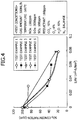
- the SO 3 reductant was added to the combustion flue gas, and the combustion flue gas containing the SO 3 reductant was allowed to flow through the catalyst of the respective Test Examples installed in the denitration and SO 3 reduction apparatus, and thereby variation of the concentration of SO 3 (ppm) in the combustion flue gas in terms of 0.03 to 0.8 (1/AV (m 2 ⁇ h/Nm 3 ) after the combustion flue gas had flowed through the catalyst layer was examined.
- the test results and the test conditions are shown in FIG. 4 .
- the concentration of SO 3 was analyzed by a deposition titration method after the sampling was done.
- AV denotes the area velocity (total contact area by gas amount/catalyst)
- 1/AV means the total contact area of the catalyst in relation to the gas amount.
- the unit of 1/AV is denoted as m 2 ⁇ h/Nm 3 .
- FIG. 4 shows variation of the concentration of SO 3 (ppm) in terms of 0.03 to 0.08 m 2 ⁇ h/Nm 3 in Test Examples 1 to 5.
- the concentration of SO 3 at the inlet of the catalyst layer did not substantially vary.
- the concentration of SO 3 at the inlet of the catalyst layer decreased from about 100 ppm to about 40 ppm at 0.06 m 2 ⁇ h/Nm 3 .
- the concentration of SO 3 at the inlet of the catalyst layer decreased from about 100 ppm to about 20 ppm at 0.08 m 2 ⁇ h/Nm 3 .
- the concentration of SO 3 at the inlet of the catalyst layer decreased from about 100 ppm to about 20 ppm at 0.08 m 2 ⁇ h/Nm 3 .
- the concentration of SO 3 at the inlet of the catalyst layer decreased from about 100 ppm to about 25 ppm at 0.08 m 2 ⁇ h/Nm 3 .
- the catalyst B was coated on a monolith base material produced by Cordierite.
- the amount of the coating was 100 g per surface area of 1 m 2 of the base material.
- the case in which methanol (CH 3 OH) was used as the SO 3 reductant was used as Test Example 8
- the case in which ethanol (C 2 H 5 OH) was used as the SO 3 reductant was used as Test Example 9.
- the case in which ammonia (NH 3 ) was used as the SO 3 reductant was used as Test Example 10.
- Example 1 the SO 3 reductant was added to the combustion flue gas, and the combustion flue gas containing the SO 3 reductant was allowed to flow through the catalyst layer using the SO 3 catalyst installed in the denitration and SO 3 reduction apparatus, and thereby variation of the concentration of SO 3 in the combustion flue gas at 0.04 to 0.08 m 2 ⁇ h/Nm 3 after the combustion flue gas had flowed through the catalyst layer.
- the variation of the concentration of SO 3 before and after the combustion flue gas had flowed through the catalyst layer was examined.
- the test conditions were the same as those of Example 1. The test results and the test conditions are shown in FIG. 5 .
- FIG. 5 shows variation of the concentration of SO 3 (ppm) in the combustion flue gas at 0.04 to 0.08 m 2 ⁇ h/Nm 3 in Test Examples 6 to 10.
- the concentration of SO 3 in the combustion flue gas at the inlet of the catalyst layer decreased.
- the concentration of SO 3 in the combustion flue gas at the inlet of the catalyst layer did not decrease.
- the concentration of SO 3 in the combustion flue gas decreased more compared with the Test Examples 8 and 9 in which CH 3 OH and C 2 H 5 OH were used as the SO 3 reductant.
- the effect of reducing the concentration of SO 3 was the most remarkable.
- a catalyst E was prepared in a similar manner as the case of preparing the catalyst B except that the ratio of TiO 2 and SiO 2 was changed to 88:12 (wt.%), that the amount of V 2 O 5 was 0.3 wt.%, and that the amount of WO 3 was 9 wt.%.
- Example 13 the catalyst E was coated onto the monolith base material produced by Cordierite.
- SO 3 reduction rate % 1 ⁇ concentration of SO 3 at catalyst layer outlet / concentration of SO 3 at catalyst layer inlet ⁇ 100
- Denitration rate % 1 ⁇ concentration of NO x at catalyst layer outlet / concentration of NO x at catalyst layer inlet ⁇ 100
- FIG. 6 shows the SO 3 reduction rate (%) and the denitration rate (%) at 0.080 m 2 ⁇ h/Nm 3 in Test Examples 11 to 18.
- the SO 3 reduction rate was 5.0%
- Test Example 12 using an alcohol the SO 3 reduction rate was 6.0%
- the SO 3 reduction rate of Test Example 13 using a saturated hydrocarbon was 10.0%
- Test Example 14 using an unsaturated hydrocarbon was 20.0%, which were high values.
- the SO 3 reduction rate of Test Example 15 was 58.0%
- the SO 3 reduction rate of Test Example 16 was 50.2%
- the SO 3 reduction rate of Test Example 17 was 54.2%
- the SO 3 reduction rate of Test Example 18 was 63.5%, which were very high values.
- test Examples 11 and 12 using alcohols the denitration rate of Test Example 11 was 92.6%, and the denitration rate of Test Example 12 was 93.2%.
- Test Examples 13 and 14 using a saturated hydrocarbon and an unsaturated hydrocarbon the denitration rate of Test Example 13 was 94.1 %, and the denitration rate of Test Example 14 was 94.0%, which were high values.
- Test Examples 15 to 18 using ⁇ 3C unsaturated hydrocarbons the denitration rate of Test Example 15 was 95.1 %, the denitration rate of Test Example 16 was 92.1 %, the denitration rate of Test Example 17 was 92.3%, and the denitration rate of Test Example 18 was 91.8%, which were sufficiently high values.
- a catalyst having another composition was prepared and the effect of reducing SO 3 into SO 2 and the denitration rate depending on the catalyst composition was examined.
- a catalyst including zirconia (ZrO 2 ) only was prepared.
- a powder of zirconium oxychloride (ZrOCl 2 ) was fired at 500°C for 5 hours, and the obtained powder was used as the catalyst G.
- a catalyst including cerium oxide (Ce 2 O 3 ) only was prepared.
- a powder of cerium nitrate (Ce(NO 3 ) 2 ) was fired at 500°C for 5 hours, and the obtained powder was used as the catalyst H.
- FIG. 7 shows the SO 3 reduction rate (%) and the denitration rate (%) at 0.080 m 2 ⁇ h/Nm 3 in Test Examples 19 to 24.
- the SO 3 reduction rate of Test Example 19 was 16.5%
- the SO 3 reduction rate of Test Example 23 was 23.1%
- the SO 3 reduction rate of Test Example 24 was 11.1%.
- the SO 3 reduction rate of Test Example 20 was 52.2%
- the SO 3 reduction rate of Test Example 21 was 47.3%
- the SO 3 reduction rate of Test Example 22 was 46.6%.
- test Examples 19, 23, and 24 in which an oxide including a single component was used, the denitration rate of Test Example 19 was 32.8%, the denitration rate of Test Example 23 was 6.7%, and the denitration rate of Test Example 24 was 19.1 %.
- Test Examples 20 to 22 in which a complex oxide containing TiO 2 was used the denitration rate of Test Example 20 was 60.4%, the denitration rate of Test Example 21 was 39.3%, and the denitration rate of Test Example 22 was 42.3%.
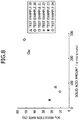
- the solid acid amount in Test Examples 19 to 24 was measured by a pyridine thermal adsorption desorption method. More specifically, the same amount of 25 mg of a powder of quartz was added to the respective Test Example and the mixture was fixed in a quartz glass tube with Kaowool. The quartz glass tube was installed in an electric furnace installed in FID gas chromatography, then the reaction mixture was treated under the condition of the temperature of 450°C for 30 minutes in a helium (He) gas stream. Then the electric furnace was maintained at 150°C, pyridine was injected by 0.5 ⁇ l for 4 to 6 times until saturation in terms of pulse was obtained, and the pyridine was adsorbed to the respective Test Examples. Then the temperature of the electric furnace was raised at the rate of 30°C/min, the desorbed pyridine was measured by FID gas chromatography, and the solid acid amount of the respective Test Examples was determined based on the obtained peak value in TPD spectrum.
- He helium
- FIG. 8 shows the relationship between the solid acid amount ( ⁇ mol/g ⁇ cata) and the SO 3 reduction rate (%) measured in the respective Test Examples 19 to 24.
- the SO 3 reduction rate was high. From these results, it was found that it became more effective for reduction of SO 3 as the solid acid amount increased.
- a catalyst having yet another composition was prepared and the effect of an active metal for reducing SO 3 into SO 2 and the denitration rate were examined.
- Example 25 80 wt.% water was added to 20 wt.% catalyst H, and the mixture was pulverized by wet ball mill to obtain wash coat slurry, and then the slurry was coated onto a ceramic base material including kaolinite as its main component, and the obtained piece was used as Test Example 25.
- the coating amount for each Test Example was measured similarly to Example 3, i.e., about 100 g/m 2 . Table 2 shows the composition of the respective Test Examples.
- Table 2 - Test Example Composition 2 Catalyst composition Load of active component Active Component Carrier Test Example 25 - TiO 2 -SiO 2 - Test Example 26 V 2 O 5 3.0/3.5 Test Example 27 MoO 3 3.0/5.5 Test Example 28 Ag 0.7/1.0 Test Example 29 WO 3 3.0/8.9 Test Example 30 Mn 2 O 3 3.0/3.0 Test Example 31 NiO 3.0/2.9 Test Example 32 Co 3 O 4 3.0/3.1
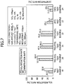
- FIG. 9 shows the SO 3 reduction rate (%) and the denitration rate (%) at 0.1m 2 ⁇ h/Nm 3 in Test Examples 24 to 32.
- the SO 3 reduction rate of Test Example 25 was 52.2%.
- the SO 3 reduction rate of Test Example 26 was 11.4%
- the SO 3 reduction rate of Test Example 27 was 44.5%
- the SO 3 reduction rate of Test Example 28 was 45.8%.
- the SO 3 reduction rate of Test Example 29 was 56.0%
- the SO 3 reduction rate of Test Example 30 was 48.3%
- the SO 3 reduction rate of Test Example 31 was 41.8%
- the SO 3 reduction rate of Test Example 32 was 39.7%.
- the denitration rate of Test Example 25 was 60.4%.
- the denitration rate of Test Example 26 was 94.4%
- the denitration rate of Test Example 27 was 82.4%
- the denitration rate of Test Example 28 was 55.5%
- the denitration rate of Test Example 29 was 73.4%
- the denitration rate of Test Example 30 was 50.9%
- the denitration rate of Test Example 31 was 46.2%
- the denitration rate of Test Example 32 was 44.3%.
- a catalyst having yet another composition was prepared and both the SO 3 reduction capability and the denitration capability were evaluated.
- a catalyst I in which V 2 O 5 -WO 3 was carried on TiO 2 , was prepared in a similar manner as the case of preparing the catalyst B except that 0.3 wt.% V 2 O 5 was carried by using ammonium metavanadate and 9 wt.% WO 3 was simultaneously carried by using ammonium paratungstate, per 100 wt.% of complex oxide, and the catalyst I was used as Test Example 33.
- a catalyst J in which V 2 O 5 -WO 3 was carried on a TiO 2 -SiO 2 complex oxide, was prepared in a similar manner as the case of preparing the catalyst B except that 0.3 wt.% V205 was carried and 9 wt.% WO 3 was simultaneously carried, per 100 wt.% of complex oxide, and the catalyst J was used as Test Example 33.
- the catalyst J was coated with metallosilicate at 25 g/m 2 to obtain a catalyst K, and the obtained catalyst K was used as Test Example 35.
- the catalyst B was used as Test Example 36.
- a catalyst L in which V 2 O 5 -WO 3 was carried on TiO 2 , was prepared in a similar manner as the case of preparing the catalyst B except that 0.7 wt.% V 2 O 5 was carried and 9 wt.% WO 3 was simultaneously carried, per 100 wt.% of complex oxide, and the catalyst L was used as Test Example 37.
- Figure 3 shows the composition of the respective Test Examples.
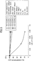
- FIG. 10 shows the SO 3 reduction rate (%) at 0.1 (1/AV: m 2 ⁇ h/Nm 3 ) in Test Examples 33 to 37.
- the SO 3 reduction rate of Test Example 33 was 33.3%.
- the SO 3 reduction rate of Test Example 34 was 58.4%
- the SO 3 reduction rate of Test Example 35 was 75.6%
- the SO 3 reduction rate of Test Example 36 was 68.6%
- the SO 3 reduction rate of Test Example 37 was 79.9%.
- FIG. 11 shows the rate of denitration (%) from the combustion flue gas at 0.10 (1/AV: m 2 ⁇ h/Nm 3 ) in Test Examples 33 to 37.
- the denitration rate of Test Example 33 was 95.3%
- the denitration rate of Test Example 34 was 95.1%
- the denitration rate of Test Example 35 was 91.1%
- the denitration rate of Test Example 36 was 91.4%
- the denitration rate of Test Example 37 was 91.8%.
- the flue gas treatment method and the denitration and SO 3 reduction apparatus of the present invention it is made possible to denitrate NO x in the combustion flue gas and reduce the concentration of SO 3 in the combustion flue gas at the same time at treatment costs lower than those conventionally.
Landscapes
- Chemical & Material Sciences (AREA)
- Engineering & Computer Science (AREA)
- Chemical Kinetics & Catalysis (AREA)
- Materials Engineering (AREA)
- Organic Chemistry (AREA)
- Environmental & Geological Engineering (AREA)
- Analytical Chemistry (AREA)
- Biomedical Technology (AREA)
- Health & Medical Sciences (AREA)
- General Chemical & Material Sciences (AREA)
- Oil, Petroleum & Natural Gas (AREA)
- Crystallography & Structural Chemistry (AREA)
- Physics & Mathematics (AREA)
- Thermal Sciences (AREA)
- Exhaust Gas Treatment By Means Of Catalyst (AREA)
- Catalysts (AREA)
Claims (14)
- Abgasbehandlungsverfahren, umfassend die Schritte:Hinzufügen eines olefinischen 3C-5C-Kohlenwasserstoffs (ungesättigten Kohlenwasserstoffs) als erstes Additiv zu einem SO3 sowie NOx beinhaltenden Verbrennungsabgas; und anschließend,Inkontaktbringen des Verbrennungsabgases mit einem Katalysator, welcher ein aus einem oder mehreren Elementen ausgewählt aus der Gruppe bestehend aus Ti, Si, Zr und Ce bestehendes Oxid und/oder ein aus zwei oder mehreren Elementen ausgewählt aus der Gruppe bestehendes Mischoxid und/oder komplexes Oxid als Träger umfasst und welcher kein Edelmetall umfasst, wodurch SO3 zu SO2 reduziert wird.
- Abgasbehandlungsverfahren nach Anspruch 1, wobei es sich bei dem olefinischen 3C-5C-Kohlenwasserstoff (ungesättigten Kohlenwasserstoff) um eines oder mehrere ausgewählt aus der Gruppe bestehend aus C3H6, C4H8 und C5H10 handelt.
- Abgasbehandlungsverfahren nach Anspruch 2, wobei das C4H8 in Form eines geometrischen Isomers oder eines racemischen Körpers vorliegt, oder/und das C5H10 in Form eines geometrischen Isomers oder eines racemischen Körpers vorliegt.
- Abgasbehandlungsverfahren nach einem der Ansprüche 1 bis 3, wobei der Träger ein eines oder mehrere ausgewählt aus der Gruppe bestehend aus TiO2-SiO2, TiO2-ZrO2 und TiO2-CeO2 umfassendes Mischoxid und/oder komplexes Oxid umfasst.
- Abgasbehandlungsverfahren nach einem der Ansprüche 1 bis 4, wobei es sich bei dem Katalysator um einen Katalysator handelt, in welchem ein eines oder mehrere ausgewählt aus der Gruppe bestehend aus V2O5, WO3 , MoO3 , Mn2O3, MnO2, NiO und Co3O4 umfassendes Metalloxid auf dem als Träger fungierenden komplexen Oxid geträgert ist.
- Abgasbehandlungsverfahren nach Anspruch 5, wobei ein Metallsilikat-basiertes komplexes Oxid, in welchem zumindest ein Teil von A1 und/oder Si in einer Zeolith-Kristallstruktur durch eines oder mehrere ausgewählt aus der Gruppe bestehend aus Ti, V, Mn, Fe und Co substituiert ist, auf den Katalysator aufgebracht ist.
- Abgasbehandlungsverfahren nach einem der Ansprüche 1 bis 6, wobei die Behandlung für die Reduktion von SO3 zu SO2 in einem Temperaturbereich von 250°C bis 450°C durchgeführt wird.
- Abgasbehandlungsverfahren nach Anspruch 7, wobei die Behandlung für die Reduktion von SO3 zu SO2 in einem Temperaturbereich von 300°C bis 400°C durchgeführt wird.
- SO3-Reduktionsvorrichtung (5, 15, 25) für die Denitrierung von NOx und die Reduktion von SO3 in einem NOx und SO3 umfassenden Verbrennungsabgas, wobei die Vorrichtung umfasst:eine erste Injektionsvorrichtung (6, 16, 26), welche dazu ausgelegt ist, einen olefinischen 3C-5C-Kohenwasserstoff (ungesättigten Kohlenwasserstoff) zu dem Verbrennungsabgas hinzuzufügen;eine zweite Injektionsvorrichtung (7, 17, 27), welche in der Nähe der ersten Injektionsvorrichtung (6, 16, 26) angeordnet ist und welche dazu ausgelegt ist, NH3 zu dem Verbrennungsabgas hinzuzufügen; undeine Katalysatorschicht (8, 18, 19, 28, 29), welche einen Katalysator umfasst, durch den das Verbrennungsabgas hindurchströmen darf,wobei die SO3-Reduktionsvorrichtung (5, 15, 25) dazu ausgelegt ist, in dem Verbrennungsabgas gleichzeitig eine Denitrierung von NOx und eine Reduktion von SO3 zu SO2 zu bewirken und eine der nachfolgenden Konfigurationen (a) und (b) umfasst:(a) die erste Injektionsvorrichtung (6) und die zweite Injektionsvorrichtung (7) sind stromaufwärts der Katalysatorschicht (8) angeordnet, oder(b) die Katalysatorschicht (18, 19, 28, 29) umfasst eine erste Katalysatorschicht (18, 28), welche stromabwärts der ersten Injektionsvorrichtung (16, 26) angeordnet ist und welche dazu ausgelegt ist, die Konzentration an SO3 zu verringern, und eine zweite Katalysatorschicht (19, 29), welche stromabwärts der zweiten Injektionsvorrichtung (17, 27) angeordnet ist und welche dazu ausgelegt ist, eine Denitrierung zu bewirken, wobei:(b1) die erste Katalysatorschicht (18) stromabwärts der zweiten Katalysatorschicht (19) angeordnet ist, die erste Injektionsvorrichtung (16) stromaufwärts der ersten Katalysatorschicht (18) und stromabwärts der zweiten Katalysatorschicht (19) angeordnet ist, und die zweite Injektionsvorrichtung (17) stromaufwärts der zweiten Katalysatorschicht (19) angeordnet ist, oder(b2) die erste Katalysatorschicht (28) stromabwärts der zweiten Katalysatorschicht (29) angeordnet ist, die erste Injektionsvorrichtung (26) stromaufwärts der ersten Katalysatorschicht (26) und stromaufwärts der zweiten Katalysatorschicht (29) angeordnet ist, und die zweite Injektionsvorrichtung (27) stromaufwärts der zweiten Katalysatorschicht (29) angeordnet ist,und wobei der Katalysator der Katalysatorschicht (8) oder der ersten Katalysatorschicht (18, 28) kein Edelmetall umfasst und ein eines oder mehrere Elemente ausgewählt aus der Gruppe bestehend aus Ti, Si, Zr und Ce umfassendes Oxid und/oder ein zwei oder mehrere Elemente ausgewählt aus der Gruppe umfassendes Mischoxid und/oder komplexes Oxid als Träger umfasst.
- SO3-Reduktionsvorrichtung nach Anspruch 9, wobei die erste Injektionsvorrichtung (6, 16, 26) dazu ausgelegt ist, eines oder mehrere ausgewählt aus der Gruppe bestehend aus C3H6, C4H8 und C5H10 zu dem Verbrennungsabgas hinzuzufügen.
- SO3-Reduktionsvorrichtung nach Anspruch 10, wobei die erste Injektionsvorrichtung (6, 16, 26) dazu ausgelegt ist, C4H8 in Form eines geometrischen Isomers oder eines racemischen Körpers zu dem Verbrennungsabgas hinzuzufügen, oder/und C5H10 in Form eines geometrischen Isomers oder eines racemischen Körpers zu dem Verbrennungsabgas hinzuzufügen.
- SO3-Reduktionsvorrichtung nach einem der Ansprüche 9 bis 11, wobei der Träger ein eines oder mehrere ausgewählt aus der Gruppe bestehend aus TiO2-SiO2, TiO2-ZrO2 und TiO2-CeO2 umfassendes Mischoxid und/oder komplexes Oxid umfasst.
- SO3-Reduktionsvorrichtung nach einem der Ansprüche 9 bis 12, wobei es sich bei dem Katalysator um einen Katalysator handelt, in welchem ein eines oder mehrere ausgewählt aus der Gruppe bestehend aus V2O5, WO3, MoO3, Mn2O3, MinO2, NiO und Co3O4 umfassendes Metalloxid auf dem als Träger fungierenden komplexen Oxid geträgert ist.
- SO3-Reduktionsvorrichtung nach Anspruch 9, wobei der Katalysator der zweiten Katalysatorschicht (19, 29) das Edelmetall nicht umfasst und ein eines oder mehrere Elemente ausgewählt aus der Gruppe bestehend aus Ti, Si, Zr und Ce umfassendes Oxid und/oder ein zwei oder mehrere Elemente ausgewählt aus der Gruppe umfassendes Mischoxid und/oder komplexes Oxid als Träger umfasst.
Applications Claiming Priority (2)
| Application Number | Priority Date | Filing Date | Title |
|---|---|---|---|
| JP2014227577A JP5748894B1 (ja) | 2014-11-07 | 2014-11-07 | 排ガス処理方法及び脱硝・so3還元装置 |
| PCT/JP2015/067449 WO2016072110A1 (ja) | 2014-11-07 | 2015-06-17 | 排ガス処理方法及び脱硝・so3還元装置 |
Publications (3)
| Publication Number | Publication Date |
|---|---|
| EP3045220A1 EP3045220A1 (de) | 2016-07-20 |
| EP3045220A4 EP3045220A4 (de) | 2016-10-05 |
| EP3045220B1 true EP3045220B1 (de) | 2018-05-09 |
Family
ID=53718500
Family Applications (1)
| Application Number | Title | Priority Date | Filing Date |
|---|---|---|---|
| EP15783949.9A Active EP3045220B1 (de) | 2014-11-07 | 2015-06-17 | Abgasbehandlungsverfahren und denitrifikations-/so3-reduktionsvorrichtung |
Country Status (8)
| Country | Link |
|---|---|
| US (1) | US20160236145A1 (de) |
| EP (1) | EP3045220B1 (de) |
| JP (1) | JP5748894B1 (de) |
| KR (1) | KR101789902B1 (de) |
| CN (1) | CN105813714B (de) |
| ES (1) | ES2674558T3 (de) |
| TW (1) | TWI599397B (de) |
| WO (1) | WO2016072110A1 (de) |
Families Citing this family (14)
| Publication number | Priority date | Publication date | Assignee | Title |
|---|---|---|---|---|
| JP5748895B1 (ja) * | 2014-11-07 | 2015-07-15 | 三菱日立パワーシステムズ株式会社 | 排ガス処理システム及び処理方法 |
| JP6535555B2 (ja) * | 2015-09-14 | 2019-06-26 | 三菱日立パワーシステムズ株式会社 | ボイラ |
| CN105214720B (zh) * | 2015-10-14 | 2017-11-10 | 无锡威孚环保催化剂有限公司 | 用于机动车尾气nox消除的分子筛催化剂的制备方法 |
| CN106040247A (zh) * | 2016-05-30 | 2016-10-26 | 中船重工海博威(江苏)科技发展有限公司 | 一种用于氨选择性催化氧化的催化剂及其制备方法 |
| CN106179397B (zh) * | 2016-06-27 | 2019-04-30 | 翁夏翔 | 一种钯钌型汽油车用催化剂及其制备方法 |
| BR112019012724A2 (pt) * | 2016-12-20 | 2019-11-26 | Umicore Ag & Co Kg | dispositivo catalisador scr contendo óxido de vanádio e peneira molecular contendo ferro |
| CN107308783B (zh) * | 2017-08-31 | 2021-02-26 | 山东瑞嘉通风环保科技有限公司 | 一种烟气湿法同时脱硫脱硝工艺 |
| JP2021508760A (ja) * | 2017-12-18 | 2021-03-11 | ビーエーエスエフ キューテック インコーポレーテッドBASF Qtech Inc. | 触媒コーティング、作製方法、およびその使用 |
| TWI731290B (zh) * | 2019-01-14 | 2021-06-21 | 富利康科技股份有限公司 | 應用陶纖濾管之低溫觸媒脫硝除塵的方法及設備 |
| CN109985619A (zh) * | 2019-04-15 | 2019-07-09 | 湖北省轻工业科学研究设计院 | 一种高效烟气处理scr脱硝催化剂及其制备方法 |
| CN111167274B (zh) * | 2020-01-19 | 2021-11-12 | 中南大学 | 一种从冶炼烟气中脱除三氧化硫的方法及其脱除装置 |
| CN112495157A (zh) * | 2020-09-30 | 2021-03-16 | 山东大学 | 一种协同脱除三氧化硫及氯化氢的装置及工艺 |
| CN112426861A (zh) * | 2020-11-11 | 2021-03-02 | 福建三宝钢铁有限公司 | 一种高效脱硫脱硝系统及方法 |
| CN113070072B (zh) * | 2021-03-30 | 2023-10-27 | 西安建筑科技大学 | 一种用于脱硫脱硝催化剂及其制备方法 |
Family Cites Families (26)
| Publication number | Priority date | Publication date | Assignee | Title |
|---|---|---|---|---|
| JPS49133269A (de) * | 1973-04-26 | 1974-12-20 | ||
| JPS52122293A (en) * | 1976-04-08 | 1977-10-14 | Nippon Shokubai Kagaku Kogyo Co Ltd | Catalyst for purifying nox |
| DE2811788A1 (de) * | 1977-03-23 | 1978-09-28 | Johnson Matthey Co Ltd | Katalysator fuer die verwendung in einem sauerstoff und schwefeldioxid enthaltenden gasstrom |
| JPS6090043A (ja) * | 1983-10-21 | 1985-05-21 | Nippon Shokubai Kagaku Kogyo Co Ltd | 窒素酸化物浄化用触媒 |
| US5260043A (en) * | 1991-08-01 | 1993-11-09 | Air Products And Chemicals, Inc. | Catalytic reduction of NOx and carbon monoxide using methane in the presence of oxygen |
| DE4132168A1 (de) * | 1991-09-27 | 1993-04-01 | Huels Chemische Werke Ag | Verfahren zur entfernung von stickoxiden aus abgasen |
| JPH07227523A (ja) * | 1993-12-24 | 1995-08-29 | Sakai Chem Ind Co Ltd | 窒素酸化物接触還元方法 |
| JPH0884912A (ja) * | 1994-09-16 | 1996-04-02 | Sakai Chem Ind Co Ltd | 高効率窒素酸化物還元方法 |
| JPH09201531A (ja) * | 1996-01-29 | 1997-08-05 | Toyota Central Res & Dev Lab Inc | 排ガス浄化用触媒及び排ガス浄化方法 |
| JP3495527B2 (ja) * | 1996-10-28 | 2004-02-09 | 三菱重工業株式会社 | 三酸化硫黄還元処理方法 |
| JP3495542B2 (ja) * | 1997-02-17 | 2004-02-09 | 三菱重工業株式会社 | 三酸化硫黄還元処理方法 |
| JP3495591B2 (ja) | 1998-03-20 | 2004-02-09 | 三菱重工業株式会社 | 排ガス中の窒素酸化物及びso3の還元処理方法 |
| CN1108849C (zh) * | 1999-06-23 | 2003-05-21 | 中国石油化工集团公司 | 一种氮氧化物的脱除方法 |
| JP2004255342A (ja) * | 2003-02-27 | 2004-09-16 | Mitsubishi Heavy Ind Ltd | 排ガス処理システムおよび排ガス処理方法 |
| AU2004232536B2 (en) * | 2003-04-17 | 2010-01-21 | Johnson Matthey Public Limited Company | Method of decomposing nitrogen dioxide |
| JP2005028210A (ja) * | 2003-07-07 | 2005-02-03 | Mitsubishi Heavy Ind Ltd | 排ガス処理システム |
| JP4508597B2 (ja) * | 2003-10-17 | 2010-07-21 | 三菱重工業株式会社 | So3の還元処理が可能な排ガス処理用触媒、その製造方法、及び該排ガス処理用触媒を用いた排ガス処理方法 |
| JP2005279372A (ja) * | 2004-03-29 | 2005-10-13 | Osaka Gas Co Ltd | 脱硝触媒およびそれを用いた脱硝方法 |
| JP4813830B2 (ja) * | 2004-10-14 | 2011-11-09 | 三菱重工業株式会社 | 排ガス処理触媒、排ガス処理方法および排ガス処理装置 |
| US7491676B2 (en) * | 2004-10-19 | 2009-02-17 | Millennium Inorganic Chemicals | High activity titania supported metal oxide DeNOx catalysts |
| WO2012132683A1 (ja) * | 2011-03-29 | 2012-10-04 | 三菱重工業株式会社 | 砒素化合物の除去方法、脱硝触媒の再生方法、並びに、脱硝触媒 |
| CN103842076A (zh) * | 2011-08-03 | 2014-06-04 | 庄信万丰股份有限公司 | 挤出蜂窝状催化剂 |
| US8844269B2 (en) * | 2012-03-16 | 2014-09-30 | Cummins Inc. | Aftertreatment system and method for pre-decomposed reductant solution |
| JP2014126298A (ja) * | 2012-12-26 | 2014-07-07 | Mitsubishi Heavy Ind Ltd | 排ガス中のso3含有量計測装置、重質燃料焚ボイラシステム及びその運転方法 |
| BR112015022045B1 (pt) * | 2013-03-14 | 2021-12-21 | Basf Corporation | Sistema híbrido de catalisador de redução catalítica seletiva |
| JP5748895B1 (ja) * | 2014-11-07 | 2015-07-15 | 三菱日立パワーシステムズ株式会社 | 排ガス処理システム及び処理方法 |
-
2014
- 2014-11-07 JP JP2014227577A patent/JP5748894B1/ja active Active
-
2015
- 2015-06-17 US US14/888,112 patent/US20160236145A1/en not_active Abandoned
- 2015-06-17 EP EP15783949.9A patent/EP3045220B1/de active Active
- 2015-06-17 ES ES15783949.9T patent/ES2674558T3/es active Active
- 2015-06-17 WO PCT/JP2015/067449 patent/WO2016072110A1/ja not_active Ceased
- 2015-06-17 CN CN201580000668.9A patent/CN105813714B/zh active Active
- 2015-06-17 KR KR1020157031311A patent/KR101789902B1/ko active Active
- 2015-10-30 TW TW104135870A patent/TWI599397B/zh active
Non-Patent Citations (1)
| Title |
|---|
| None * |
Also Published As
| Publication number | Publication date |
|---|---|
| TW201630651A (zh) | 2016-09-01 |
| KR20160068695A (ko) | 2016-06-15 |
| WO2016072110A1 (ja) | 2016-05-12 |
| TWI599397B (zh) | 2017-09-21 |
| ES2674558T3 (es) | 2018-07-02 |
| JP2016087576A (ja) | 2016-05-23 |
| CN105813714B (zh) | 2017-10-27 |
| EP3045220A4 (de) | 2016-10-05 |
| EP3045220A1 (de) | 2016-07-20 |
| JP5748894B1 (ja) | 2015-07-15 |
| CN105813714A (zh) | 2016-07-27 |
| KR101789902B1 (ko) | 2017-10-25 |
| US20160236145A1 (en) | 2016-08-18 |
Similar Documents
| Publication | Publication Date | Title |
|---|---|---|
| EP3045220B1 (de) | Abgasbehandlungsverfahren und denitrifikations-/so3-reduktionsvorrichtung | |
| EP3177386B1 (de) | Gezonter katalysator zur behandlung von abgasen | |
| US9545602B2 (en) | Catalytic article for treating exhaust gas | |
| JP7472014B2 (ja) | リーン/リッチシステムのための自動車排気からのn2o除去 | |
| KR101634390B1 (ko) | 질소 산화물의 형성을 줄이거나 방지하는 암모니아와 일산화탄소의 이중 산화용 촉매 | |
| KR20140027062A (ko) | 선택 환원형 촉매, 및 그것을 이용한 배기가스 정화 장치 및 배기가스 정화 방법 | |
| BR112017028424B1 (pt) | Compósito catalisador de remoção de óxido nitroso, sistema de tratamento de emissões, e, método para tratar gases de escape | |
| US11229901B2 (en) | SCR catalyst device containing vanadium oxide and molecular sieve containing iron | |
| US11300029B2 (en) | SCR catalyst device containing vanadium oxide and molecular sieve containing iron | |
| US8178064B2 (en) | Treatment of power utilities exhaust | |
| JP2020508843A (ja) | ディーゼルエンジンの排気ガス浄化用触媒 | |
| JP2008002451A (ja) | ディーゼルエンジン用排気ガス浄化装置およびディーゼルエンジンの排気ガスの浄化方法 | |
| US20100303697A1 (en) | Selective Catalytic Reduction System and Process for Treating NOx Emissions Using a Zinc or Titanium Promoted Palladium-Zirconium Catalyst | |
| Gunnarsson et al. | Combining HC-SCR over Ag/Al2O3 and hydrogen generation over Rh/CeO2-ZrO2 using biofuels: An integrated system approach for real applications | |
| KR20190030225A (ko) | 디젤 산화 촉매 컨버터 | |
| JP2005081189A (ja) | 高温排ガス用脱硝触媒 | |
| KR100590308B1 (ko) | 디젤 자동차용 배기가스 정화용 촉매의 제조 방법 및 이로부터 제조된 촉매 | |
| RU2772861C2 (ru) | Каталитическое изделие для обработки выхлопных газов | |
| JPS62171750A (ja) | 窒素酸化物と一酸化炭素の同時処理用触媒 |
Legal Events
| Date | Code | Title | Description |
|---|---|---|---|
| PUAI | Public reference made under article 153(3) epc to a published international application that has entered the european phase |
Free format text: ORIGINAL CODE: 0009012 |
|
| 17P | Request for examination filed |
Effective date: 20151030 |
|
| AK | Designated contracting states |
Kind code of ref document: A1 Designated state(s): AL AT BE BG CH CY CZ DE DK EE ES FI FR GB GR HR HU IE IS IT LI LT LU LV MC MK MT NL NO PL PT RO RS SE SI SK SM TR |
|
| AX | Request for extension of the european patent |
Extension state: BA ME |
|
| A4 | Supplementary search report drawn up and despatched |
Effective date: 20160902 |
|
| RIC1 | Information provided on ipc code assigned before grant |
Ipc: B01J 23/22 20060101ALI20160829BHEP Ipc: B01J 23/10 20060101ALI20160829BHEP Ipc: B01J 23/28 20060101ALI20160829BHEP Ipc: B01J 23/30 20060101ALI20160829BHEP Ipc: B01J 23/652 20060101ALI20160829BHEP Ipc: B01J 23/34 20060101ALI20160829BHEP Ipc: B01J 23/75 20060101ALI20160829BHEP Ipc: B01D 53/86 20060101AFI20160829BHEP Ipc: B01J 23/755 20060101ALI20160829BHEP Ipc: B01J 29/076 20060101ALI20160829BHEP |
|
| 17Q | First examination report despatched |
Effective date: 20170627 |
|
| GRAP | Despatch of communication of intention to grant a patent |
Free format text: ORIGINAL CODE: EPIDOSNIGR1 |
|
| DAV | Request for validation of the european patent (deleted) | ||
| DAX | Request for extension of the european patent (deleted) | ||
| INTG | Intention to grant announced |
Effective date: 20171208 |
|
| RIN1 | Information on inventor provided before grant (corrected) |
Inventor name: HIGASHINO, KOJI Inventor name: FUJIKAWA, KEIJI Inventor name: YONEMURA, MASANAO Inventor name: SAWATA, AKIHIRO |
|
| GRAS | Grant fee paid |
Free format text: ORIGINAL CODE: EPIDOSNIGR3 |
|
| GRAA | (expected) grant |
Free format text: ORIGINAL CODE: 0009210 |
|
| AK | Designated contracting states |
Kind code of ref document: B1 Designated state(s): AL AT BE BG CH CY CZ DE DK EE ES FI FR GB GR HR HU IE IS IT LI LT LU LV MC MK MT NL NO PL PT RO RS SE SI SK SM TR |
|
| REG | Reference to a national code |
Ref country code: GB Ref legal event code: FG4D |
|
| REG | Reference to a national code |
Ref country code: CH Ref legal event code: EP Ref country code: AT Ref legal event code: REF Ref document number: 997070 Country of ref document: AT Kind code of ref document: T Effective date: 20180515 |
|
| REG | Reference to a national code |
Ref country code: IE Ref legal event code: FG4D |
|
| REG | Reference to a national code |
Ref country code: DE Ref legal event code: R096 Ref document number: 602015011021 Country of ref document: DE |
|
| REG | Reference to a national code |
Ref country code: ES Ref legal event code: FG2A Ref document number: 2674558 Country of ref document: ES Kind code of ref document: T3 Effective date: 20180702 |
|
| REG | Reference to a national code |
Ref country code: NL Ref legal event code: MP Effective date: 20180509 |
|
| REG | Reference to a national code |
Ref country code: LT Ref legal event code: MG4D |
|
| PG25 | Lapsed in a contracting state [announced via postgrant information from national office to epo] |
Ref country code: BG Free format text: LAPSE BECAUSE OF FAILURE TO SUBMIT A TRANSLATION OF THE DESCRIPTION OR TO PAY THE FEE WITHIN THE PRESCRIBED TIME-LIMIT Effective date: 20180809 Ref country code: LT Free format text: LAPSE BECAUSE OF FAILURE TO SUBMIT A TRANSLATION OF THE DESCRIPTION OR TO PAY THE FEE WITHIN THE PRESCRIBED TIME-LIMIT Effective date: 20180509 Ref country code: NO Free format text: LAPSE BECAUSE OF FAILURE TO SUBMIT A TRANSLATION OF THE DESCRIPTION OR TO PAY THE FEE WITHIN THE PRESCRIBED TIME-LIMIT Effective date: 20180809 Ref country code: FI Free format text: LAPSE BECAUSE OF FAILURE TO SUBMIT A TRANSLATION OF THE DESCRIPTION OR TO PAY THE FEE WITHIN THE PRESCRIBED TIME-LIMIT Effective date: 20180509 Ref country code: SE Free format text: LAPSE BECAUSE OF FAILURE TO SUBMIT A TRANSLATION OF THE DESCRIPTION OR TO PAY THE FEE WITHIN THE PRESCRIBED TIME-LIMIT Effective date: 20180509 |
|
| PG25 | Lapsed in a contracting state [announced via postgrant information from national office to epo] |
Ref country code: NL Free format text: LAPSE BECAUSE OF FAILURE TO SUBMIT A TRANSLATION OF THE DESCRIPTION OR TO PAY THE FEE WITHIN THE PRESCRIBED TIME-LIMIT Effective date: 20180509 Ref country code: LV Free format text: LAPSE BECAUSE OF FAILURE TO SUBMIT A TRANSLATION OF THE DESCRIPTION OR TO PAY THE FEE WITHIN THE PRESCRIBED TIME-LIMIT Effective date: 20180509 Ref country code: RS Free format text: LAPSE BECAUSE OF FAILURE TO SUBMIT A TRANSLATION OF THE DESCRIPTION OR TO PAY THE FEE WITHIN THE PRESCRIBED TIME-LIMIT Effective date: 20180509 Ref country code: HR Free format text: LAPSE BECAUSE OF FAILURE TO SUBMIT A TRANSLATION OF THE DESCRIPTION OR TO PAY THE FEE WITHIN THE PRESCRIBED TIME-LIMIT Effective date: 20180509 Ref country code: GR Free format text: LAPSE BECAUSE OF FAILURE TO SUBMIT A TRANSLATION OF THE DESCRIPTION OR TO PAY THE FEE WITHIN THE PRESCRIBED TIME-LIMIT Effective date: 20180810 |
|
| REG | Reference to a national code |
Ref country code: AT Ref legal event code: MK05 Ref document number: 997070 Country of ref document: AT Kind code of ref document: T Effective date: 20180509 |
|
| PG25 | Lapsed in a contracting state [announced via postgrant information from national office to epo] |
Ref country code: SK Free format text: LAPSE BECAUSE OF FAILURE TO SUBMIT A TRANSLATION OF THE DESCRIPTION OR TO PAY THE FEE WITHIN THE PRESCRIBED TIME-LIMIT Effective date: 20180509 Ref country code: PL Free format text: LAPSE BECAUSE OF FAILURE TO SUBMIT A TRANSLATION OF THE DESCRIPTION OR TO PAY THE FEE WITHIN THE PRESCRIBED TIME-LIMIT Effective date: 20180509 Ref country code: CZ Free format text: LAPSE BECAUSE OF FAILURE TO SUBMIT A TRANSLATION OF THE DESCRIPTION OR TO PAY THE FEE WITHIN THE PRESCRIBED TIME-LIMIT Effective date: 20180509 Ref country code: RO Free format text: LAPSE BECAUSE OF FAILURE TO SUBMIT A TRANSLATION OF THE DESCRIPTION OR TO PAY THE FEE WITHIN THE PRESCRIBED TIME-LIMIT Effective date: 20180509 Ref country code: DK Free format text: LAPSE BECAUSE OF FAILURE TO SUBMIT A TRANSLATION OF THE DESCRIPTION OR TO PAY THE FEE WITHIN THE PRESCRIBED TIME-LIMIT Effective date: 20180509 Ref country code: EE Free format text: LAPSE BECAUSE OF FAILURE TO SUBMIT A TRANSLATION OF THE DESCRIPTION OR TO PAY THE FEE WITHIN THE PRESCRIBED TIME-LIMIT Effective date: 20180509 Ref country code: AT Free format text: LAPSE BECAUSE OF FAILURE TO SUBMIT A TRANSLATION OF THE DESCRIPTION OR TO PAY THE FEE WITHIN THE PRESCRIBED TIME-LIMIT Effective date: 20180509 |
|
| REG | Reference to a national code |
Ref country code: CH Ref legal event code: PL |
|
| REG | Reference to a national code |
Ref country code: DE Ref legal event code: R097 Ref document number: 602015011021 Country of ref document: DE |
|
| PG25 | Lapsed in a contracting state [announced via postgrant information from national office to epo] |
Ref country code: SM Free format text: LAPSE BECAUSE OF FAILURE TO SUBMIT A TRANSLATION OF THE DESCRIPTION OR TO PAY THE FEE WITHIN THE PRESCRIBED TIME-LIMIT Effective date: 20180509 Ref country code: IT Free format text: LAPSE BECAUSE OF FAILURE TO SUBMIT A TRANSLATION OF THE DESCRIPTION OR TO PAY THE FEE WITHIN THE PRESCRIBED TIME-LIMIT Effective date: 20180509 |
|
| REG | Reference to a national code |
Ref country code: BE Ref legal event code: MM Effective date: 20180630 |
|
| PLBE | No opposition filed within time limit |
Free format text: ORIGINAL CODE: 0009261 |
|
| STAA | Information on the status of an ep patent application or granted ep patent |
Free format text: STATUS: NO OPPOSITION FILED WITHIN TIME LIMIT |
|
| REG | Reference to a national code |
Ref country code: IE Ref legal event code: MM4A |
|
| PG25 | Lapsed in a contracting state [announced via postgrant information from national office to epo] |
Ref country code: MC Free format text: LAPSE BECAUSE OF FAILURE TO SUBMIT A TRANSLATION OF THE DESCRIPTION OR TO PAY THE FEE WITHIN THE PRESCRIBED TIME-LIMIT Effective date: 20180509 Ref country code: LU Free format text: LAPSE BECAUSE OF NON-PAYMENT OF DUE FEES Effective date: 20180617 |
|
| 26N | No opposition filed |
Effective date: 20190212 |
|
| PG25 | Lapsed in a contracting state [announced via postgrant information from national office to epo] |
Ref country code: IE Free format text: LAPSE BECAUSE OF NON-PAYMENT OF DUE FEES Effective date: 20180617 Ref country code: FR Free format text: LAPSE BECAUSE OF NON-PAYMENT OF DUE FEES Effective date: 20180709 Ref country code: LI Free format text: LAPSE BECAUSE OF NON-PAYMENT OF DUE FEES Effective date: 20180630 Ref country code: CH Free format text: LAPSE BECAUSE OF NON-PAYMENT OF DUE FEES Effective date: 20180630 |
|
| PG25 | Lapsed in a contracting state [announced via postgrant information from national office to epo] |
Ref country code: SI Free format text: LAPSE BECAUSE OF FAILURE TO SUBMIT A TRANSLATION OF THE DESCRIPTION OR TO PAY THE FEE WITHIN THE PRESCRIBED TIME-LIMIT Effective date: 20180509 Ref country code: BE Free format text: LAPSE BECAUSE OF NON-PAYMENT OF DUE FEES Effective date: 20180630 |
|
| PG25 | Lapsed in a contracting state [announced via postgrant information from national office to epo] |
Ref country code: AL Free format text: LAPSE BECAUSE OF FAILURE TO SUBMIT A TRANSLATION OF THE DESCRIPTION OR TO PAY THE FEE WITHIN THE PRESCRIBED TIME-LIMIT Effective date: 20180509 |
|
| PG25 | Lapsed in a contracting state [announced via postgrant information from national office to epo] |
Ref country code: MT Free format text: LAPSE BECAUSE OF NON-PAYMENT OF DUE FEES Effective date: 20180617 |
|
| GBPC | Gb: european patent ceased through non-payment of renewal fee |
Effective date: 20190617 |
|
| PG25 | Lapsed in a contracting state [announced via postgrant information from national office to epo] |
Ref country code: TR Free format text: LAPSE BECAUSE OF FAILURE TO SUBMIT A TRANSLATION OF THE DESCRIPTION OR TO PAY THE FEE WITHIN THE PRESCRIBED TIME-LIMIT Effective date: 20180509 |
|
| PG25 | Lapsed in a contracting state [announced via postgrant information from national office to epo] |
Ref country code: GB Free format text: LAPSE BECAUSE OF NON-PAYMENT OF DUE FEES Effective date: 20190617 |
|
| PG25 | Lapsed in a contracting state [announced via postgrant information from national office to epo] |
Ref country code: PT Free format text: LAPSE BECAUSE OF FAILURE TO SUBMIT A TRANSLATION OF THE DESCRIPTION OR TO PAY THE FEE WITHIN THE PRESCRIBED TIME-LIMIT Effective date: 20180509 |
|
| PG25 | Lapsed in a contracting state [announced via postgrant information from national office to epo] |
Ref country code: HU Free format text: LAPSE BECAUSE OF FAILURE TO SUBMIT A TRANSLATION OF THE DESCRIPTION OR TO PAY THE FEE WITHIN THE PRESCRIBED TIME-LIMIT; INVALID AB INITIO Effective date: 20150617 Ref country code: MK Free format text: LAPSE BECAUSE OF NON-PAYMENT OF DUE FEES Effective date: 20180509 Ref country code: CY Free format text: LAPSE BECAUSE OF FAILURE TO SUBMIT A TRANSLATION OF THE DESCRIPTION OR TO PAY THE FEE WITHIN THE PRESCRIBED TIME-LIMIT Effective date: 20180509 |
|
| PG25 | Lapsed in a contracting state [announced via postgrant information from national office to epo] |
Ref country code: IS Free format text: LAPSE BECAUSE OF FAILURE TO SUBMIT A TRANSLATION OF THE DESCRIPTION OR TO PAY THE FEE WITHIN THE PRESCRIBED TIME-LIMIT Effective date: 20180909 |
|
| PGFP | Annual fee paid to national office [announced via postgrant information from national office to epo] |
Ref country code: DE Payment date: 20250429 Year of fee payment: 11 |
|
| PGFP | Annual fee paid to national office [announced via postgrant information from national office to epo] |
Ref country code: ES Payment date: 20250701 Year of fee payment: 11 |