EP3423659B1 - Profilé composite pour porte, fenêtre ou façade et procédé de fabrication dudit profilé composite - Google Patents
Profilé composite pour porte, fenêtre ou façade et procédé de fabrication dudit profilé composite Download PDFInfo
- Publication number
- EP3423659B1 EP3423659B1 EP17709603.9A EP17709603A EP3423659B1 EP 3423659 B1 EP3423659 B1 EP 3423659B1 EP 17709603 A EP17709603 A EP 17709603A EP 3423659 B1 EP3423659 B1 EP 3423659B1
- Authority
- EP
- European Patent Office
- Prior art keywords
- groove
- web
- wall
- profile
- composite
- Prior art date
- Legal status (The legal status is an assumption and is not a legal conclusion. Google has not performed a legal analysis and makes no representation as to the accuracy of the status listed.)
- Active
Links
Images






Classifications
-
- E—FIXED CONSTRUCTIONS
- E06—DOORS, WINDOWS, SHUTTERS, OR ROLLER BLINDS IN GENERAL; LADDERS
- E06B—FIXED OR MOVABLE CLOSURES FOR OPENINGS IN BUILDINGS, VEHICLES, FENCES OR LIKE ENCLOSURES IN GENERAL, e.g. DOORS, WINDOWS, BLINDS, GATES
- E06B3/00—Window sashes, door leaves, or like elements for closing wall or like openings; Layout of fixed or moving closures, e.g. windows in wall or like openings; Features of rigidly-mounted outer frames relating to the mounting of wing frames
- E06B3/04—Wing frames not characterised by the manner of movement
- E06B3/263—Frames with special provision for insulation
- E06B3/273—Frames with special provision for insulation with prefabricated insulating elements held in position by deformation of portions of the metal frame members
-
- E—FIXED CONSTRUCTIONS
- E06—DOORS, WINDOWS, SHUTTERS, OR ROLLER BLINDS IN GENERAL; LADDERS
- E06B—FIXED OR MOVABLE CLOSURES FOR OPENINGS IN BUILDINGS, VEHICLES, FENCES OR LIKE ENCLOSURES IN GENERAL, e.g. DOORS, WINDOWS, BLINDS, GATES
- E06B3/00—Window sashes, door leaves, or like elements for closing wall or like openings; Layout of fixed or moving closures, e.g. windows in wall or like openings; Features of rigidly-mounted outer frames relating to the mounting of wing frames
- E06B3/04—Wing frames not characterised by the manner of movement
- E06B3/263—Frames with special provision for insulation
- E06B3/26301—Frames with special provision for insulation with prefabricated insulating strips between two metal section members
- E06B3/26303—Frames with special provision for insulation with prefabricated insulating strips between two metal section members with thin strips, e.g. defining a hollow space between the metal section members
Definitions
- the present invention relates to a composite profile, preferably a thermally insulated composite profile, in particular in a fire protection version, according to the preamble of claim 1 as well as a sash or window frame for a door, a window or a facade element and a method for producing the composite profile.
- Smoke protection doors according to DIN 18095 are self-closing doors that largely prevent the passage of smoke when installed and closed.
- a fire protection barrier on the other hand, has the additional task of protecting openings in walls against the passage of fire.
- the profiles or sections of profiles which are usually produced by an extrusion process or an extrusion process or a roll forming process, as well as the connecting webs each have joining surfaces in the form of a tongue-and-groove connection, which are used to join profiles, in particular metal profiles. and from insulating webs designed as connecting webs to composite profiles.
- the respective joining surfaces of the profiles and the connecting bars must be provided with coordinated tolerances so that the profiles and the connecting bars can be pushed into one another during assembly.
- a profile area that can be plastically deformed - usually a web-like projection, hereinafter also referred to as a foot - is then plastically deformed by a so-called rolling process in such a way that a positive and non-positive connection is achieved - i.e. a shear-resistant composite - is created between the respective profiles and connecting webs and a composite profile is formed.
- the profiles and connecting webs to be connected to one another can be made from different materials, such as metal or plastic or combinations of materials.
- At least two profiles are used, which form a composite profile, but composite profiles are known that consist of more than two individual profiles.
- a preferred embodiment, particularly for fire protection structures consists of two light metal, in particular aluminum, profiles, which are connected to one or more connecting webs or insulating webs.
- two light metal profiles, in particular aluminum profiles are connected to one or more connecting webs made of plastic, whereby the plastic webs can be provided with metallic bridge sections.
- the bridge sections from a more heat-resistant plastic than the remaining connecting webs, which can then be made of polyamide, for example.
- the webs then preferably have recesses.
- outer functional grooves and inner grooves for receiving external threads mean that the relative length of the connecting webs, which essentially defines the width of the space between the metallic profiles, is limited or relatively short.
- the state of the art with regard to connecting devices and connecting methods for composite profiles includes: DE 30 25 706 A1 , the EP 0 311 850 A2 , the EP 2 163 719 A2 as well as the WO8403326A1 .
- the DE 30 25 706 A1 shows a device for rolling or connecting profiles and connecting webs.
- the DE 30 25 706 A1 further shows that the roller tools for forming the deformation bars - require a considerable amount of space. This means it is not possible to get above the hammers - so Arrange further functional grooves in the area in which the roller tools are used when assembling the composite profile.
- Such functional grooves can therefore only be positioned laterally next to the space required for the roller tools. This limits the width of the connecting webs or the entire composite profile must be made wider in order to integrate connecting webs with a longer cross-section, which would have improved thermal insulation properties.
- the hammers are in the EP 0 311 850 A2 pressed or rolled approximately at right angles onto the connecting bars.
- a hammer is rolled in the same plane or parallel to the connecting bar.
- the EP 2 163 719 A2 describes a common and well-proven assembly method for composite profiles.
- several pairs of rollers each with different roller diameters, are used.
- the rollers are used in pairs so that each can apply an appropriate counterforce.
- three, four or five of these pairs of rollers are arranged directly one behind the other on an assembly device.
- This method is pronounced of a rolling process on a rolling train with several rolling stands, in which each rolling stand of the rolling train contributes a defined, discrete amount to the desired overall thickness reduction of the rolling stock.
- the rollers usually have a structure on their circumference, for example a corrugation, in order to be able to transmit feed forces to the composite profile in addition to the forming forces.
- the parts of the composite profile are connected to one another in one operation and pushed or pulled through the assembly tools.
- rollers often have a shoulder so that they can roll over existing side grooves without undesirably deforming and thus damaging the profile or grooves.
- a paragraph otherwise has no further function for the composite profiles.
- the WO8403326A1 discloses that the hammer can also have a web with a structured cross-sectional geometry, so that this hammer not only presses on the connecting web at a 90 ° angle, but additionally forces are also applied in the direction parallel to the connecting web. Also reveals the WO8403326A1 that the rollers can have beveled peripheral sides, so that in addition to radial forces, axial forces also become effective on the roller circumference during the rolling process.
- DE2755669B1 discloses a composite profile for a frame or a casement of a window, a door or a facade element.
- DE202007016649U1 also discloses a composite profile.
- FR2411950A1 and EP0765989A1 disclose a method for producing a composite profile.
- the object of the present invention is to create a preferably thermally insulated composite profile, in particular in a fire protection version, for the production of casement and/or frames for doors, windows or facade elements, which at least partially overcomes the disadvantages of the prior art.
- the invention solves this problem through the subject matter of claim 1, the subject matter of the independent claim 10 and the method of claim 14.
- a composite profile according to the invention can, for example, form part of a blind or sash frame of a window or a facade element. It is particularly preferably designed in a fire version.
- a preferred one Variant of the composite profile according to the invention is used in a smoke protection door according to DIN 18095, preferably also in a fire protection element, such as a fire protection door or a fire protection window, at least in a T-30 fire protection version.
- the composite profile according to the invention has an insulating web and at least one first metal profile connected to the insulating web.
- the insulating web can preferably be designed as a connecting web between two metal profiles.
- the insulating web has at least one edge foot, which is also referred to below as a reinforced end region. This can, for example, and advantageously be designed as a skirting board.
- the foot is held in at least a first groove in the metal profile.
- the interaction between the foot and the groove prevents the foot from being pulled out of the groove.
- the foot and the groove preferably form a tongue and groove connection.
- the maximum diameter of the foot i.e. the diameter of the foot cross section
- the maximum diameter of the foot can be larger than the opening width of the groove opening.
- a kind of undercut groove is then formed.
- the cross-section of the foot is essentially polygonal, in particular trapezoidal.
- the aforementioned first groove has at least one groove opening.
- the groove opening can have edges, which, however, preferably do not protrude into the groove space of the groove.
- the edge of the groove has a first groove wall delimiting the first groove.
- This is assigned to the metal profile and has at least one integral (integral means in one piece) formed angled web or leg.
- the entirety of the integrally formed web/leg and the first groove wall can also be referred to as a functional contour.
- integrated means “in one piece” within the scope of the description and claims.
- the integrally formed web/leg delimits at least one second groove together with the first groove wall.
- the second groove will have at least one further limiting groove wall, for example a base wall of the metal profile, It preferably has at least one base wall and two side walls.
- the base wall merges into the side walls at its ends.
- the side walls end in a groove opening.
- the second groove is designed such that the first groove wall also forms the base wall of the second groove.
- This second groove can preferably be essentially U-shaped.
- the first groove for receiving the foot of the insulating profile also has at least one base wall and two side walls, as well as a groove opening.
- the first groove wall can be designed as a side wall or as a longitudinal leg of the preferably U-shaped first groove.
- the second groove has a groove opening which is arranged above or below the foot of the insulating bar when the insulating bar is imaginary horizontally aligned.
- the insulating bar can also be aligned vertically in a composite profile, depending on the orientation, for example in the window or door frame.
- the horizontal alignment of the composite web discussed here therefore only refers to an imaginary installation position and serves to define the position of the groove opening in relation to the composite web in this exemplary installation position.
- the first groove wall or the second groove wall has at least one projection or a series of projections. This projection protrudes into the first groove.
- the projection should therefore not be confused with the edge of the groove opening.
- the projection can, for example, protrude into the groove space of the groove from an edge of the groove opening, which is integrally formed on the first groove wall.
- the projection allows for improved clamping of the foot in the first groove.
- the second groove offers another option for defining further functional elements of the composite profile.
- the first and second grooves share a common groove wall. This makes a particularly compact structure possible.
- the projection is pressed onto or into the material of the insulating web.
- the metal profile can have a base wall from which the first delimiting groove wall and a second delimiting groove wall of the first groove protrude.
- a region of the base wall can form the second groove at least together with the integrally formed web and the first groove wall, whereby the grooves are designed in a particularly material-saving manner.
- the first groove wall forms the bottom of the second groove.
- the second groove has at least one notch on one or more groove walls for positively locking a frame element.
- the notch can be provided with a notch center and a first notch wall and a second notch wall, the first notch wall being steeper than the second notch wall. This makes it possible, for example, to create a locking lug for receiving and securing a locking means of an optional component.
- the projection can also be formed by a wire.
- the second groove can advantageously have a groove opening with an opening plane which runs perpendicular or substantially perpendicular to the base wall.
- the insulating web can be arranged as a connecting web between the metal profile, as a first metal profile, and a second metal profile, each of the metal profiles having the respective first and second grooves and wherein a mirror plane runs through the insulating web and wherein the first and second grooves of the first metal profile can preferably be brought into congruence with the first and second grooves of the second metal profile when reflected on the mirror plane.
- Both The metal profiles can have grooves of the same size as the first metal profile.
- the first and second grooves of the first metal profile preferably face the first and second grooves of the second metal profile.
- the web formed integrally on the first groove wall can preferably run parallel or substantially parallel to the base wall.
- Fixing the foot by reshaping at least one of the integrally formed webs or at least one projection on one of the integrally formed webs in such a way that the cross section and/or the width of the groove opening of the first groove is/are changed.
- At least the first groove is reshaped by applying a force to the web end of the integrally formed web in such a way that the cross section and/or the width of the groove opening is/are reduced.
- the forming of at least the first groove takes place integrally by applying a force to the projection designed web such that the cross section and / or the width of the groove opening is / are reduced.
- the change, preferably reduction, of the cross section or the width or width of the groove opening of the first groove can take place until a contour of the final composite profile according to the invention is reached, in which the foot and thus the insulating web can no longer be removed from the first groove. In this way, a tongue-and-groove connection is easily formed, which lies directly below another groove.
- the respective foot of the insulating web (also known as a connecting web) can be fastened in this way, although it also lies directly below a second groove.
- a deformation of the second groove or a web on the second groove (outside) is therefore used in order to achieve the fastening of the insulating web in the respective first groove.
- an L-shaped contour can be used as a hammer on the second groove, which is pivoted as a whole in order to reduce the width of the first groove, or a small web on the outside of this L-shaped contour is pivoted in order to to fix or lock the foot in the first groove, in turn reducing the opening width of the first groove.
- One or more rollers can be positioned at different points on the hammer.
- An attachment on both legs/bars of the L-shaped hammer is possible.
- One leg of the L-shaped hammer is a web that has a free end and the other is the bottom of the L-shaped groove. It is possible to act on the free end of the web (called the web end or front side) with the at least one roller. Alternatively, it is also possible to act laterally at an angle on the web (inside in the groove or on the outside of the groove on this web). Finally, as an alternative, it is also possible to act on the leg with the at least one roller at the bottom of the groove.
- the aim in each case is to pivot the hammer essentially as a whole from a position that is slightly inclined in the initial state relative to the base wall into a right-angled or essentially perpendicular position to the base wall and to anchor the foot of the connecting web in the adjacent groove.
- the second groove wall of the first groove, in which the foot is arranged, is used as an anvil for the rolling process. It serves as a kind of abutment for the rolling of the L-shaped hammer.
- the second groove wall of the first groove into which the foot of the connecting web engages, as a hammer and to use the L-shaped contour on the opposite side of the first groove as the anvil for the rolling process.
- the L-shaped functional contour in the initial state is preferably already aligned at right angles or essentially at right angles to the base wall.
- the web, which forms the second groove wall of the first groove is then the hammer, which is pivoted in the direction of this anvil.
- the at least one roller is then placed on this web and rolled along it in the main direction of extension of the metal profile.
- At least two mutually parallel or essentially parallel connecting webs are provided on the composite profile, each of which engages with its feet in first grooves of two opposing metal profiles.
- a hollow chamber is then created between the metal profiles and the two connecting webs.
- the forming for fastening the feet in the respective groove then takes place from this initial state according to one of the variants of the method described above or below as according to the invention.
- an L-shaped functional contour on each of the four feet is pivoted from an oblique starting position to the respective base wall into a perpendicular position by means of one or more rollers that are rolled along it, which is done by means of one or more of the Rolling takes place in order to reduce the opening width or the cross section of the first groove in which the foot engages.
- the second groove is then located directly next to the first groove, but outside the hollow chamber and is preferably opened towards the side facing away from the hollow chamber. This process is particularly advantageous for producing this composite profile.
- the L-shaped functional contour is then used as a hammer and rolled.
- one or more rollers can be pulled through the hollow chamber so that the side web located there on the first groove is used as a hammer.
- a projection can also be rolled onto the second groove.
- the force exerted on the end of the web is transmitted to the web by at least one roller of a tool resting on the end of the web.
- the roller has at least a first and a second cylindrical surface, the first cylindrical surface resting on the web end of the web and serving for forming, and the second cylindrical surface resting on a surface of the composite profile that runs essentially perpendicular to the base wall of the metal profile and thus serves for guidance.
- One of the two cylinder lateral surfaces of the roller is preferably rougher than the second cylinder lateral surface of the roller.
- the roller can preferably have a corrugation in order to enable better advance of the tool on the metal profile and/or the insulating web.
- the groove opening of the second groove can be advantageously expanded.
- the projection of the first delimiting groove wall can be at least partially pressed onto or into the material of the foot of the insulating web during forming.
- At least two rollers, or three or more rollers, each with two cylindrical lateral surfaces can be used, the circumference of a first cylindrical lateral surface being the same for both rollers and the circumference of the second cylindrical lateral surface being larger for a second of the two rollers than for the first of the two rolls and the first roll and then the second roll are used for forming.
- a disadvantage of the methods mentioned in the prior art is that complex profile geometries could not be deformed using the previously known methods. Most of the time, relatively simple hammers are used that have no other functions besides their actual function as a deformable connecting and holding element.
- the present method allows the relative width of the connecting webs to be increased in relation to the overall width of the respective composite profile.
- the entire width of the composite profile should not be influenced.
- a profile construction of a metal profile is used in such a way that the connection to a composite profile is also achieved.
- the rolling can be carried out in particular by pairs of rollers which, due to their geometry, are able to reshape the aforementioned grooves in the correct position.
- the invention makes it possible to use relatively wide connecting webs. This improves thermal insulation (both at ambient temperatures and in the event of a fire) and makes the installation of other components, such as fire protection insulators, corner connectors, fittings and the like, much easier.
- the invention also creates a sash or frame for a door, a window or a facade element, which consists of several composite profiles according to one of the claims related thereto and a door or a window with a sash and a frame made of composite profiles according to one or more of the thereon related claims, wherein a fold area is formed between the sash and the frame, and wherein the second grooves are open towards the fold area and the first grooves for receiving the feet of the respective insulating webs lie directly behind the second grooves from the fold area.
- the insulating web can advantageously have a particularly large width compared to the width of the composite profile and functional grooves can still be implemented on the frame, for example for receiving fasteners or the like.
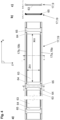
- Fig. 1 shows a door 1, which has a wing with a sash frame 2, which is arranged on a frame 3.
- the sash frame 2 is rotatably mounted on the frame 3.
- the door 1 is shown as a swing door with door hinges.
- the door 1 can also be designed as a sliding door.
- the present invention can also be used for windows or facade elements. If the term “door” is used below, it can therefore also be replaced by the terms “window” or “facade element”.
- the door can be arranged on the frame so that it can rotate (vertical axis of rotation) and/or pivot (horizontal axis of rotation).
- the profile composite forms an at least U-shaped sash frame 2 or a closed sash frame.
- a surface element 8 such as an insulating glass pane or fire protection glazing or a metal or plastic plate is inserted into the casement 2.
- the sash frame 2 and the surface element 8 together form the sash.
- the term “window” also includes fixed glazing with a surface element in a frame 3.
- the frame 3 of the door 1 is also U-shaped here and has a horizontal frame spar 9 and two vertical frame spars 10, 11.
- the sash frame 2 and/or the frame 3 can alternatively also be designed to be closed all around and have further lower horizontal bars.
- each composite profile 300 and / or 400 each has at least one metal, in particular light metal profile - here two profiles 12, 13 or 14, 15 - which are connected by at least one connecting web - here each connected by two connecting webs 16, 17 or 18, 19 - of which in Fig. 2 but only one is shown at a time.
- the composite profile 300 or 400 can also have more than two profiles and more than two connecting webs 16, 17.
- the connecting webs are also referred to as insulating profiles in the context of this application.
- the insulating profiles 16 to 19 also form connecting profiles, which then connect the metal profiles. This is the case with the embodiments described below.
- composite profiles are also conceivable, which consist of only a single metal profile and a single insulating web.
- the outer profile 13 can alternatively also be located on the inside.
- the composite profile 300 can also be part of a door 1 or a window that is located completely inside the building and, for example, divides or closes off a corridor.
- the terms inside and outside are used here only to simplify understanding.
- the respective hollow chamber 20a, 21a can also have fewer than two webs 22a, 22b or 23a, 23b or more than two webs 22a, 22b or 23a, 23b.
- the webs 22a, 22b and 23a, 23b can also extend through the entire hollow chamber 20a, 21a.
- the inner profile 12 and the outer profile 13 can each have more than one hollow chamber 20a, 21a.
- Two insert strips 24a, 24b or 25a, 25b with fire-retardant properties are inserted into the hollow chambers 20a, 21a, which are each held in their position by the webs 22a, 22b or 23a, 23b.
- more than two or less than two insert strips 24a, 24b or 25a, 25b with fire-retardant properties can be inserted into the hollow chamber(s) 20a, 21a.
- the insert strips 24a, 24b or 25a, 25b with fire-retardant properties are strips that can absorb a certain fire heat or energy in the event of a fire and/or can actively cool. They can consist of a molded body with a high heat capacity, for example made of concrete. However, they can also consist of one or more shaped bodies that contain heat-binding hydrophilic adsorbent (see e.g DE 197 00 696 C and DE 4443762 A1 ).
- the inner profile 12 and the outer profile 13 of the composite profile 300 are each in Fig. 2 Example shown made from a light metal by extrusion.
- the inner profile 12 and the outer profile 13 of the composite profile 300 can also be made from other suitable materials for window profiles - such as steel, plastic - or a composite thereof using appropriate manufacturing processes - such as extrusion, through a machining process or roll profiling or roll forming or a combination be made from it.
- the inner profile 12 and the outer profile 13 of the frame are connected by a first connecting web 16 and preferably a second connecting web 17 (see also Fig. 4 ) - connected to each other in a form-fitting and force-fitting manner in the manner of a shear-resistant bond.
- the first connecting web 16 of the frame is oriented towards the masonry when installed ( Fig.2 lower edge of the drawing) and the other connecting web 17 towards a rebate area towards the sash frame 1.
- the composite profile 300 has an interior IR 1 in the manner of an inner chamber between the metal profiles 12, 13 and the connecting webs 16, 17.
- first connecting web 18 and the second connecting web 19 are connected by at least the first connecting web 18 and the second connecting web 19 (see also Fig. 3 ) - connected to each other in a form-fitting and force-fitting manner in the manner of a shear-resistant connection.
- the first connecting web 18 of the sash frame is to Surface element 8 or oriented towards the “glass rebate” and the second connecting web 19 towards the rebate area towards the frame 1.
- the insulating and connecting webs 16, 17, 18, 19 have base areas that are made of a plastic material, for example by extrusion. This gives them good thermal insulation properties. They also point in the main extension direction X (perpendicular to the image plane of the Fig. 2 and 3 ) spaced apart stiffeners 65 (see Fig. 4 ), which extend over the entire width Z of the connecting webs 16 to 19 and which consist of a material that is more heat-resistant than the plastic material, such as a light metal, in particular aluminum, steel or a more heat-resistant plastic.
- the stiffeners 65 engage in the metal profiles 12, 13 or 14 and 15 and are particularly advantageous for the fire protection function because they burn or melt away later than the base areas of the connecting webs 16 - 19. They can have the same heat resistance as the metal profiles. This is the case if they are made of the same metal as the metal profiles.
- the first connecting web 16 and the second connecting web 17 are each held in two first grooves 26a, 26b, and 27a, 27b, which are arranged in the inner profile 12 and in the outer profile 13, respectively.
- the connecting webs 17 and 19 of the window frame 2 and the sash frame 1 facing the fold area between the window frame and the sash frame are in a preferred embodiment Fig. 4 shown.
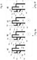
- the connecting web or webs 17, 19 have a main extension direction X. When installed, this is also the main extension direction X of the composite profile (perpendicular to the image plane, for example Fig. 3 ), into which the respective connecting web 17, 19 is installed.
- the respective connecting web 17, 19 has two feet 17a, b; 19a, b in the form of two baseboards, which are preferably completely continuous in the main direction of extension, in the form of preferably advantageously (but not necessarily) widened end regions. These are used for insertion into corresponding grooves 29a, b; please refer Fig. 2 and 3 ) of the metal profiles to be connected to each other. Tongue and groove connections are preferably formed in this way.
- the respective connecting web 17, 19 also has the feet 17a, b; 19a, b connecting transverse webs 64. These transverse webs 64 extend here at an angle, in particular perpendicularly in the Z direction to the two feet 17a, b; 19a, b. The transverse webs 64 are spaced apart from one another in the main extension direction.
- the crossbars 64 and the feet 17a, b; 19a, b are made of the same material from a plastic.
- the recesses 63 are relatively large in terms of area, and are preferably larger than the material area of the crossbars 64.
- the recesses 63 extend in the main extension direction
- the recesses 63 advantageously improve the thermal insulation properties of the at least one connecting web 16. It is particularly advantageous, however, that through the at least one recess 63 fittings, such as hinges or lock cases, can be easily and therefore advantageously integrated into the composite profile 300 or 400 or mounted on it without the composite profile having to be machined.
- At least one, several or each of the transverse webs 64 has/have a stiffener 65 running parallel to it over its entire extension in the direction Z perpendicular to the main extension direction X, which is made of a more heat-resistant material than the base structure made of the less heat-resistant plastic consists. It can be made of a metallic material. This can be the same material as the material of the metal profiles. Alternatively, the stiffener 65 can also be made of a plastic material that is more heat-resistant than that from which the crossbars 64 and the feet 17a, b; 19a, b exist. The stiffener 65 is preferably attached to the respective crossbar 64 in a materially bonded manner, for example by gluing. The stiffener 65 extends into the baseboard areas or feet 17a, b; 19a, b of the respective connecting web 17, 19.
- the recesses 63 preferably have an extension X 63 in the main extension direction X of between 100 mm and 200 mm, particularly preferably between 125 mm and 175 mm.
- the recesses 63 also preferably extend in the direction Z perpendicular thereto, preferably over the entire area between the feet 17a, b; 19a, 19b, so that between the feet 17a, b; 19a, b the entire distance between the metal profiles is covered by the recess 63 in the Z direction. This is particularly preferred and makes it particularly easy to install fittings. Alternatively, the recess 63 can only extend over up to 75%, in particular up to 50%, of the width of the respective connecting web 17, 19.
- the transverse webs 64 preferably have an extension in the main extension direction X of 15 mm to 55 mm, particularly preferably between 20 mm and 35 mm.
- the stiffener 65 also extends in the main extension direction X between 5 mm and 25 mm, particularly preferably between 5 mm and 20 mm.
- the respective connecting web 17, 19 can preferably consist of a combination of simple polyamide as a base structure for the feet 17a, b; 19a, b and with heat-resistant plastic bridge sections as stiffeners 65.
- the at least one connecting web 17, 19 can also be made of a metallic material or can be made of a combination of a metallic material and a plastic material.
- the composite profiles 400 from which the casement 2 of the door 1 is constructed also each have an inner profile 14, which is assigned to an interior of a building, and an outer profile 15, the outer profile 15 generally being assigned to the side of a building exposed to the weather.
- the outer profile 15 can alternatively also be located on the inside.
- the composite profile 400 can also be part of a door 1 or a window that is located completely inside the building and, for example, divides or closes off a corridor.
- the inner profile 14 and the outer profile 15 each have at least one hollow chamber 20b, 21b, into which two second webs 22c, 22d and 23c, 23d protrude.
- the respective hollow chamber 20b, 21b can also have fewer than two webs 22c, 22d or 23c, 23d or more than two webs 22c, 22d or 23c, 23d.
- the webs 22c, 22d and 23c, 23d can also extend through the entire hollow chamber 20b, 21b.
- the inner profile 14 and the outer profile 15 can each have more than one hollow chamber 20b, 21b.
- two insert strips 24c, 24d or 25c, 25d with fire-retardant properties are inserted into the hollow chambers 20b, 21b, which are each held in their position by the webs 22c, 22d or 23c, 23d.
- more than two or less than two insert strips 24c, 24d or 25c, 25d with fire-retardant properties can be inserted into the hollow chamber(s) 20b, 21b.
- the insert strips 24c, 24d or 25c, 25d with fire-retardant properties are strips that absorb a certain amount of fire heat or energy in the event of a fire can and/or actively cool. They can consist of a molded body with a high heat capacity, for example made of concrete. However, they can also consist of one or more shaped bodies that contain heat-binding hydrophilic adsorbent (see e.g DE 197 00 696 C and DE 4443762 A1 ).
- the inner profile 14 and the outer profile 15 of the composite profile 400 are each in Fig. 2 Example shown made from a light metal by extrusion.
- the inner profile 14 and the outer profile 15 of the composite profile 400 can also be made from other suitable materials for window profiles - such as steel or plastic or a composite thereof - using appropriate manufacturing processes - such as extrusion, a machining process or roll profiling or roll forming or a combination thereof - be manufactured.
- the inner profile 14 and the outer profile 15 are connected to one another in a form-fitting and non-positive manner in the manner of a shear-resistant connection by the (already explained) connecting webs 18 and 19.
- the composite profile 400 forms an interior IR 2 .
- the composite profile 400 also has the glass rebate 30, on the side of which the surface element 8, such as an insulating glass pane, is held.
- the outer profile 15 of the composite profile 400 forms a groove 33 in an extension of a web 32 at a free end of the web 32, into which a sealing profile 34 is inserted, which creates a gap between the outer profile 15 of the Composite profile 400 and the outer profile 13 of the composite profile 300, from which the frame 3 is constructed, seals.
- This sealing profile 34 seals the rebate space 31 against the outside of the door 1.
- the inner profile 12 of the composite profile 300 forms a groove 36 in an extension of a web 35 at a free end of the web 35, into which a sealing profile 37 is inserted, which creates a gap between the inner profile 14 of the Composite profile 400 from which the sash frame 3 is constructed and seals the inner profile profile 13 of the composite profile 300.
- This sealing profile 37 seals the rebate space 31 against the inside of the door 1.
- a further groove 38 which forms a web 39 of the outer profile 15 of the composite profile 400, from which the sash frame 2 is constructed, receives a sealing profile 40 with which the outer gap between the surface element 8 and the outer profile 15 of the composite profile 400 is sealed .
- the outside sealing profile 40 is designed as a so-called contact seal.
- a glass retaining strip 42 engages in a further groove 41, which forms the inner profile 14 of the composite profile 400.
- the glass retaining strip 42 is provided with a room-side sealing profile 43, which seals the room-side gap between the surface element 18 and the glass retaining strip 42.
- the room-side sealing profile 43 is designed here as a plug-in seal and has a groove 44 via which the room-side sealing profile 43 is supported on a web 45 of the glass retaining strip 42.
- the inner profile 12 and the outer profile 13 of the composite profile 300 each point on their mutually facing or facing inner sides - i.e. the walls, which are also referred to below as base walls 66a, 66b, the inside of the respective profile 12, 13 - each above the first Grooves 27a, 27b, in which the second connecting web 17 is held, or the side of the first grooves 27a, 27b facing away from the interior IR 1 or the composite profile 300, have functional contours 46a, 46b.
- the inner profile 14 and the outer profile 15 of the composite profile 400 each have their inner sides facing or facing one another - i.e. the base walls 66c, 66d of the inside of the respective profile 14, 15 - each above the first grooves 29a, 29b, in which the second connecting web 19 is held, or on the side of the first grooves 29a, 29b facing away from the interior IR2 or the composite profile 400 (see Fig. 3 ), functional contours 47a, 47b.
- inside means the side or wall that faces the interior IR 1 , IR 2 of the respective composite profile 300, 400.
- the functional contours 47a, 47b and 46a, 46b each comprise at least one transverse leg or a first groove wall 49a, 49b or 48a, 48b, which is perpendicular to the inner sides or walls 66a facing or facing one another , 66b or 66c, 66d of the inner profile 14 or 12 and the outer profile 15 or 13 protrudes.
- a web 51a, 51b or 50a, 50b is formed, which is preferably designed as a parallel web and is parallel to the respective base wall 66a, 66b or 66c, 66d of the inner profile 14 or 12 and the outer profile 15 or 13 extends, but is shorter than this.
- the respective groove walls 49a, 49b or 48a, 48b and the web 51a, 51b or 50a, 50b essentially form an L-shape in cross section.
- the functional contours 47a, 47b and 46a, 46b each form a second groove 67a in interaction with the mutually facing or facing walls 66a, 66b or 66c, 66d of the inner profile 14 or 12 and the outer profile 15 or 13, 67b or 67c, 67d.
- These functional contours 47a, 47b and 46a, 46b are preferably designed as multiple-function contours that fulfill/implement not just one but several functions.
- the functional contours can, for example, form a fastening groove. It is advantageous if the functional contours 47a, 47b or 46a, 46b interact with the respective base walls 66a, 66b or 66c, 66d, at least two of the aforementioned functional grooves 67a, 67b or 67c, 67d limit.
- the functional contours 47a, 47b and 46a, 46b preferably have locking means such as one or more undercuts, which can interact with a corresponding locking means such as one or more locking edges. These undercuts are also referred to below as notches 69.
- the functional contours 47a, 47b or 46a, 46b can also have a thread structure (not shown here).
- the fastening grooves are preferably designed for fastening fastening elements, which preferably act in a positive and/or non-positive manner and which can be fixed in the fastening grooves by a linear movement.
- the functional grooves 67a, 67b and 67c, 67d can alternatively also take on other functions.
- the inner profile 14 and the outer profile 15 of the composite profile 400 each have their inner sides facing or facing one another - i.e. the walls 66c, 66d of the inside of the respective profile 14, 15 - each above the first grooves 27a, 27b, in which the second connecting web 19 is held, or the side of the first grooves 27a, 27b facing away from the interior IR1 or the composite profile 300 (see Fig. 3 ), functional contours 47a, 47b.
- connecting webs 16, 17 and 18, 19 are each directly below the second grooves 67a, 67b or 67c, 67d or in relation to the second grooves 67a, 67b or 67c, 67d in the direction of the interior IR1 or IR2 of the composite profile 300 or 400 are positioned.
- a method is shown with which a connecting web 17 is arranged and fastened to the metal profile 13 of the composite profile 300.
- the outer profile 13 of the composite profile 300 is shown in a detail here.
- the outer profile 13 of the composite profile 300 from which the frame 3 of the door 1 is constructed is therefore described below - in order to avoid repetitions - unless another profile 12, 14, 15 is expressly described.
- the statements therefore also apply analogously to fastening a fastening web or the same fastening web 17 to the inner profile 12 of the composite profile 300 as well as to the assembly of the connecting web 19 to the inner profile 14 and the outer profile 15 of the composite profile 400, from which the sash frame 2 is made, see to that too Fig. 2 .
- the functional contours 46a, 46b which are each formed in one piece on the inner profile 12 and outer profile 13, for example by extrusion, are formed during the assembly of the composite profile 300 in such a way that at least one (here widened) end of the connecting web 17 is positively and non-positively is connected to the inner profile 12 and outer profile 13.
- FIG. 5a the outer profile 13 of the composite profile 300 is shown in a section.
- a first groove 27b which is clearly shown, is clearly visible Fig. 5a However, it is not yet in its usable geometry, but is only brought into its usable geometry by reshaping the functional contour 46b. This unusable geometry is also called the initial contour in the context of the present invention.
- the first groove 27b has a first web-shaped groove wall 48b and a second web-shaped groove wall 52b, which delimits the groove 27b.
- the second groove wall 52b has an undercut here.
- a foot 17a - here in the form of a thickened end region of the connecting web 17 is arranged in the groove 27b.
- the (preferably thickened) end regions of the connecting webs 16, 18 and 19 are each to be understood as an edge-side foot.
- This can preferably be designed as a skirting board, similar to a piping strip and can particularly preferably extend at the edge over the entire length of the connecting web.
- the foot 17a is preferably placed on the second groove wall 52b or lies against it.
- the foot 17a of the connecting web can correspond geometrically with the undercut of the second groove wall 52b and, when resting on the second groove wall 52b, in the horizontal direction with respect to the plane of the drawing Fig. 5a be positioned in a defined manner in the groove 27b.
- the functional contour 46b also has a transverse leg, which on the one hand limits the first groove 27b as the first groove wall 48b.
- the first groove 27b is approximately U-shaped.
- the first groove wall 48b and the second groove wall 52b form the longitudinal legs of the U and a base wall 66b forms the base of the first groove 27b.
- the functional contour 46b i.e. here the first groove wall 48b and the web 50b connected to it, and a correspondingly long section of the base wall 66 together form the second groove 67.
- the base wall 66 extends in an imaginary coordinate system in the X direction. It also extends perpendicular to the plane of the drawing (in its main extension direction, which also corresponds to the direction of extrusion for producing the metal profiles).
- the first groove wall 48b and the web 50b are aligned perpendicularly or substantially perpendicularly to one another.
- the entirety of these two groove walls is inclined towards the base wall by an angle ⁇ >0°, in particular between 5° and 25°, so that the U-shaped second groove 67, starting from its base, which is formed by the first groove wall 48b, tapered towards its open side. This taper is gradually or essentially eliminated during the subsequent production in order to securely anchor the connecting web 17 in the first groove 27b with the hammer, which is formed from the first groove wall 48b and the web 66b.
- the position of the overall L-shaped hammer from the web 50b and the first one is pivoted Groove wall 48b used to reduce the opening width of the first groove 27b in order to anchor the foot of the connecting web 17 in the first groove 27b.
- the second groove 67 is opened further so that it can be easily used.
- the second groove wall 52b of the first groove 27b is located further away in relation to a corresponding outer fold area and the first groove wall 48b faces closer to the respective corresponding fold area.
- the functional contour 46b has an optional projection 53b on a side of the first groove wall 48b facing the first groove 27b, which, after the functional contour 46b has been formed, presses onto the foot 17a or the end region of the connecting web 17 and/or into the end region or engages the foot 17a and thereby ensures a positive and non-positive connection in the manner of a shear-resistant connection.
- the projection 53b can also be arranged on the second groove wall 52b in such a way that it projects into the interior of the first groove 27b, the so-called first groove space.
- the first groove wall 48b has at its transition to one in relation to the plane of the drawing Fig. 5a vertical wall, the base wall 66b, the outer profile 13 here has a wall thickness reduction 54b.
- the wall thickness 54b By reducing the wall thickness 54b as an option, the formability of the groove wall 48b and thus the formability of the functional contour 46b is advantageously improved and the forming is advantageously concentrated at a defined point on the groove wall 48b and thus the functional contour 46b.
- the cross-sectional constriction 54b therefore has the smallest thickness of the first groove wall 48b in relation to its cross section.
- FIG. 5a A first forming tool is also shown, which can be designed as a pair of rollers or rollers or can consist of two rollers. Only a first role 55a is shown here.
- rollers refers to an arrangement of the rolls analogous to a duo roll stand. Ie the rollers are in a vertical direction to the cross section of the composite profile 300 or 400, as shown in, for example Fig. 2 is shown, arranged and release a space between them, through which the parts of the composite profile to be assembled or the composite profile are guided.
- the term “pair of rollers” can also refer to an arrangement of two rollers next to each other, so that each of the two rollers arranged next to one another preferably has one functional contour 46a, 46b or 47a in a time-synchronous manner , 47b reshaped. This advantageously achieves high productivity of the process.
- the profiles can be guided under locally fixed but rotatable rollers or the rollers can also be moved linearly and rolled over the profiles, which are then preferably stationary.
- the L-shaped contour with the first groove wall 48b and the web 46b, which is formed or formed by the roller tools, is also referred to in technical language as a "hammer” because, like those, it acts on the - in corresponding technical terms it is also referred to as an "anvil".
- - Act on the second groove wall 52b and clamp the foot 17a or the thickened end region of the connecting web 17 between them.
- the connecting webs 17, 19 of the composite profiles 300, 400 can be made very long, so that they are advantageous relative to the prior art Achieve improved thermal insulation properties without having to make the composite profiles 300, 400 larger overall in relation to the glass rebate width of the composite profile 400.
- the role 55a has a paragraph 56a, which relates to the drawing level of the Fig. 5a horizontal wall of the outer profile 13 is supported.
- the defined effective diameter or the defined circumference of a first cylinder surface 68a of the roller 55a accordingly presses with a defined excess on the end face of the web 50b of the functional contour 46b, so that the functional contour 46b overall over the wall thickness reduction 54b by a defined amount (see original contour of the Webs 50b before forming in a thin solid line 5a to 5c ) is bent or deformed counterclockwise.
- the respective roller 55a-c, 60a-c and 57a, b can rest on a surface of the respective metal profile or the connecting web and enable the tool to be guided.
- This tool structure is used to produce variants of a composite profile Fig. 5 - 7 usable.
- the roller 55a and/or its counter-roller can advantageously have projections or corrugations, e.g. radial corrugations, through which a secure advance of the parts of the composite profile 300 or the composite profile 300 to be assembled is ensured.
- Fig. 5b the outer profile 13 of the composite profile 300 is shown in a section.
- FIG 5b A second forming tool is also shown, which can also be designed as a pair of rollers or rollers or can consist of two rollers and of which only a first roller 55b is also shown.
- the role 55b also has a paragraph 56b, which relates to the drawing level of the Fig. 5b horizontal wall of the outer profile 13 is supported.
- the defined cylinder circumference 68b of the roller 55b which is larger by a defined amount than the cylinder circumference 68a of the roller 55a, accordingly presses with a defined excess onto the end face of the web 50b of the functional contour 46b, so that the functional contour 46b extends overall over the cross-sectional narrowing 54b a further defined amount (see original contour of the web 50b before forming in a thin solid line) is bent or deformed counterclockwise.
- the roller 55b and / or its counter roller can also have radial corrugations, through which a safe advance of the parts of the composite profile 300 or the composite profile 300 to be assembled is ensured.
- Fig. 5c the outer profile 13 of the composite profile 300 is shown in a section.
- Fig 5c A third forming tool is also shown, which is also designed here as a pair of rollers or rollers and of which only the first roller 55c is also shown.
- the role 55c also has a paragraph 56c, which relates to the drawing level of the Fig. 5c horizontal wall of the outer profile 13 is supported.
- the defined cylinder circumference 68c of the roller 55c which is larger by a defined amount than the cylinder circumference 68b of the roller 55b, accordingly presses with a defined excess on the end face of the web 50b of the functional contour 46b.
- the functional contour 46b is bent or deformed as a whole via the cross-sectional constriction 54b by a defined amount (see original contour of the web 50b before forming in a thin solid line) counterclockwise into its usable position, so that the shape or contour of the final composite profile is achieved.
- This also gives the groove 27b its final geometry and the composite web 17 is positively and non-positively connected to the outer profile 13.
- the second groove 67b is also formed on the functional contour 46b, which can serve, for example, as a corner connector receiving groove for receiving a corner connector or as a fastening groove.
- the roller 55c and / or its counter roller can also have radial projections or corrugations, through which a safe advance of the parts of the composite profile 300 or the composite profile 300 to be assembled is ensured.
- Fig. 5a to Fig. 5c works with a three-stage forming process, whereby each forming stage or pair of rollers has a defined partial amount contributes to the transformation of the functional contour 46b into its usable position.
- the pairs of rollers are here perpendicular to the plane of the drawing in relation to a feed direction of the composite profile 300 5a to 5c arranged one behind the other.
- Fig. 6a to Fig. 6f is an alternative, but fundamentally similar, procedure Fig. 5a to Fig. 5c shown.
- the following essentially only describes deviations, changes or additions to the procedure Fig. 5a to Fig. 5c described.
- Fig. 6e The composite profile 400 shown preferably again has the outer profile 15 and the inner profile 14. The inner profile 14 is shown.
- the functional contour 47a has a projection 53c on its first groove wall 49a, which deviates from the functional contour 46b Fig. 5a to Fig. 5c is arranged in the transition area between groove wall 49b and web 51a.
- the projection 53c is intended here to engage in a geometrically corresponding recess with an undercut that the connecting web 19 has at its thickened end region or the foot 19a.
- the projection 53c preferably has a thorn or a tip or the like, which, after forming, projects into the groove space of the first groove 29a, in which the thickened end region of the connecting web 19 is arranged.
- the connecting web 19 is fixed in a positive and non-positive manner, whereby a connection is created in the manner of a shear-resistant composite perpendicular to the cross-sectional plane/image plane.
- the projection 53a or the mandrel can have a material reinforcement, such as a wire, inside the metal matrix.
- the first groove 29a is also delimited here by a second web-shaped groove wall 52a.
- the necessary reshaping is achieved by reshaping the projection 53c using rollers (pairs), which are formed from two rollers 57a, 57b.
- rollers which are formed from two rollers 57a, 57b.
- the rollers 57a, 57b each have a circumferential section 58a, 58b, which here differs from the rollers 55a, 55b, 55c Fig. 5a to Fig. 5c - Supported on the front side of the web 51a of the functional contour 47a.
- the active geometry of the rollers 57a, 57b, which is involved in the forming, is here a chamfer 59a, 59b, which has the roller 57a, 57b at its largest diameter and which faces the shoulder 58a, 58b. At its largest diameter, this chamfer opens into a cylinder surface 70e
- the chamfer 59a, 59b also generates an axially acting forming force in relation to the roller 57a, 57b, which reshapes the projection 53c of the functional contour 47a in such a way that it engages in the geometrically corresponding recess with an undercut, which the connecting web 19 has at its thickened end region, as shown in Fig. 6d and Fig. 6f is shown.
- rollers 57a, 57b and/or their respective counter rollers can each also have radial corrugations, which ensure a safe advance of the parts of the composite profile 400 to be assembled.
- the procedure according to Fig. 6a to Fig. 6f works differently from the procedure Fig. 5a to Fig. 5c - with a preferably two-stage forming process, whereby each forming stage or a pair of rollers contributes a defined partial amount to the forming of the functional contour 47a into its usable position.
- the pairs of rollers are here perpendicular to the plane of the drawing in relation to a feed direction of the composite profile 400 6b and 6c arranged one behind the other.
- an edge of the groove opening is formed by the projection 53c with a mandrel or projection extending from the edge, which presses into the groove and thus onto or into the foot of the connecting web 19 arranged therein.
- Fig. 7a to Fig. 7e is a similar procedure to that Fig. 5a to Fig. 5c shown.
- the following will therefore be summarized in essence Deviations, changes or additions to the procedure Fig. 5a to Fig. 5c described.
- Fig. 7a the outer profile 13 of the composite profile 300 is shown in a section.
- Fig. 7a shows the outer profile 13 in a state in which the functional contour has not yet reached its usable position.
- the outer profile 13 resembles the outer profile 13 Fig. 5a . Therefore, for a detailed description of the characteristics of the functional contour 46b, we refer to the description of Figures 5a to 5c referred.
- the hammer consisting of the web 46b and the first groove wall is again aligned at an angle ⁇ to the base wall 66, so that in the initial state the groove width decreases towards the open side, which is canceled out again in the course of the subsequent forming process.
- the connecting web 17 is at its foot 17a in relation to the drawing sheet level Fig. 7a fixed in the vertical direction.
- the connecting web 17 is fixed in a positive and non-positive manner, whereby a connection is created in the manner of a shear-resistant composite. This is achieved by shaping the functional contour 46b using pairs of rollers in which the rollers 60a, 60b, 60c are arranged.
- the role 60a in Fig. 7b has a circumferential shoulder 61a, which differs from the rollers 55a, 55b, 55c Fig. 5a to Fig. 5c - Supported on the front side of the web 50b of the functional contour 46b.
- the active geometry of the roller 60a which is involved in the forming, is here the peripheral surface of the shoulder 61a, which acts on the end face of the web 50b, as well as a chamfer 62a, which has the roller 60a at its largest diameter and which faces the shoulder 61a is and also acts on the web 50b.
- the area of the roller 60a with the largest outer diameter, which forms the chamfer 62a, which ends on the shoulder 61a, is here immersed in the not yet usable groove which is formed between a wall of the outer profile 13 and the web 50b of the functional contour 46b .
- the diameter of the shoulder 61a and the chamfer 62a together form a forming geometry on the roller 60a, which generates a radially acting forming force both in relation to the roller 60a through the diameter of the shoulder 61a and also an axially acting forming force through the bevel 62a, which reshape the functional contour 46b so that its projection 53b engages in the thickened end region of the connecting web 17.
- the diameter of the shoulder 61a of the roller 60a accordingly presses with a defined excess on the end face of the web 50b of the functional contour 46b, as does the chamfer 62a, which acts transversely to it, so that the second groove 67b, which connects the functional contour 46b with the wall 66b of the outer profile 13 and the second groove wall 52b of the first groove 27b after production or in the then usable state of the composite profile 300 is enlarged.
- the functional contour 46b is reduced overall over the cross-sectional narrowing 54b by a defined amount (in the Fig. 5 and 6 each example bent or deformed "counterclockwise").
- the roller 60a and / or its counter roller can also have radial projections and / or corrugations, which ensure a safe advance of the parts of the composite profile 300 to be assembled.
- Fig 7c A second forming tool is shown, which is also designed here as a pair of rollers or rollers and of which only a first roller 60b is also shown.
- the active geometry of the roller 60b is geometrically similar to the active geometry of the roller 60a.
- the diameter of the shoulder 61b in the roller 60b is larger by a defined amount than the diameter of the shoulder 61a of the roller 60b.
- the roller 60b accordingly presses with a defined excess onto the end face of the web 50b of the functional contour 46b.
- the axial extent of the shoulder 61b with respect to the roller 60b is reduced compared to the roller 60a, so that the bevel 62b is shifted parallel to the bevel 62a of the roller 60a by a defined amount in the direction of the web 50b of the functional contour 46b.
- the functional contour 46b is bent or deformed overall by a further defined amount counterclockwise via the cross-sectional constriction 54b.
- the roller 60b and / or its counter roller can also have radial corrugations, which ensure a safe advance of the parts of the composite profile 300 to be assembled.
- FIG. 7d A third forming tool is shown, which is also designed here as a pair of rollers or rollers and of which only a first roller 60c is also shown.
- the effective geometry of the roller 60c, which is involved in the forming, is here the peripheral surface of the shoulder 61c, which acts on the end face of the web 50b, as well as the peripheral surface of a cylindrical section 63 of the roller 60c, on which the roller 60c is at its largest Diameter and its largest cylinder circumference and which acts on the first groove wall 48b.
- the shoulder 61a and the section 63 together form a forming geometry on the roller 60c, which generates a radially acting forming force through the shoulder 61c in relation to the roller 60c and also a radially acting forming force through the section 63.
- the diameter of the shoulder 61c of the roller 60c accordingly presses with a defined excess on the end face of the web 50b of the functional contour 46b, just as section 63 of the roller 60c also acts with a defined excess on the first groove wall 48b of the functional contour 46b.
- the functional contour 46b is bent or deformed overall by a defined amount counterclockwise via the wall thickness reduction 54b. This also gives the groove 27b its final geometry and the composite web 17 is positively and non-positively connected to the outer profile 13.
- the functional contour 46b thereby also shapes the second groove 67b between the web 50b and the base wall 66b of the outer profile 13 into a usable state out of.
- the second groove 67b serves, for example, as a corner connector receiving groove for receiving a corner connector or as a fastening groove.
- the roller 60c and / or its counter roller can also have radial corrugations, which ensure a safe advance of the parts of the composite profile 300 to be assembled.
- Fig. 7e the outer profile 13 is shown with the fully assembled composite web 17 without a forming tool.
- Fig. 7a to Fig. 7e works - analogously to the method according to FIGS. 5a to 5d - with a three-stage forming process, with each forming stage or a pair of rollers contributing a defined partial amount to the transformation of the functional contour 46b into its usable position.
- the pairs of rollers are here perpendicular to the plane of the drawing in relation to a feed direction of the composite profile 300 7a to 7e each arranged one behind the other.
- the web end of the web 50b or the web 50b of the functional contour 46b is guided by the two active surfaces of the rollers 60a, 60b, 60c during the respective forming process, so that the forming process takes place with a high degree of dimensional precision.
- the following procedure is given for assembling the composite profile 300, 400: First, the inner profile 12 or 14 and the outer profile 13 or 15, the at least one connecting web 16, 17 or 18, 19 as well as the forming tools, which are each designed here as pairs of rollers according to a preferred but not mandatory variant and which are in the 5a to 5c or 5a to 5d or 7b to 7d are only shown in sections.
- the inner profile 12 or 14 and the outer profile 13 or 15 are prepared together with the at least one connecting web 16, 17 or 18, 19, in which the inner profile 12 or 14, the connecting web 16, 17 or .18, 19 and the outer profile 13 and 15 are in the correct position relative to each other be positioned and aligned so that the connecting web 16, 17 or 18, 19 to be assembled engages in the grooves 27a, 27b or 29a, 29b.
- the inner profile 12 or 14 and the outer profile 13 or 15 are assembled together with the at least one connecting web 16, 17 or 18, 19 in a third method step by at least a first roller in a first forming step, in which the defined effective geometry of the Rollers 55a, 57a, 60a of the first forming tool presses with a defined oversize onto the functional contour 46a, 46b or 47a, 47b, so that the functional contour 46a, 46b or 47a, 47b or at least sections of the functional contour 46a, 46b or 47a, 47b is/are bent or deformed by a defined amount (based on the drawing: “counterclockwise”).
- the functional contours 46a, 46b and 47a, 47b are advantageously designed as multiple-function contours.
- the effective geometry of the respective roller 55a, 57a, 60a can each be an effective diameter or a chamfer 59a or 62a or a combination of the effective diameter and the chamfer 59a or 62a.
- the rollers 55a, 57a, 60a can have their own drive.
- the rollers 55a, 57a, 60a each have radial corrugations, which ensure a safe advance of the parts of the composite profile 300 or the composite profile 300 to be assembled. If the rollers 55a, 57a, 60a do not have their own drive, the parts of the respective composite profile 300, 400 to be assembled or the composite profiles 300, 400 to be assembled are driven, i.e. put into a feed movement, or the rollers are moved over the composite profile(s). guided or rolled along them (moved over them).
- the inner profile 12 or 14 and the outer profile 13 or 15 are assembled together with the at least one connecting web 16, 17 or 18, 19 by the second forming tool in a second forming step in which the defined active geometry of the rollers 55b, 57b, 60b of the second forming tool presses with a defined oversize onto the functional contour 46a, 46b or 47a, 47b, so that the functional contour 46a, 46b or 47a, 47b or at least sections of the functional contour 46a, 46b or 47a, 47b around one a defined amount is/are bent or deformed counterclockwise.
- the functional contours 46a, 46b and 47a, 47b are advantageously designed as multiple-function contours.
- the effective geometry of the respective roller 55b, 57b, 60b can be an effective diameter or a chamfer 59b or 62b or a combination of the effective diameter and the chamfer 59b or 62b.
- the rollers 55b, 57b, 60b can in turn have their own drive.
- the rollers 55b, 57b, 60b each have radial corrugations, which ensure a safe advance of the parts of the composite profile 300 or the composite profile 300 to be assembled. If the rollers 55b, 57b, 60b do not have their own drive, the parts of the respective composite profile 300, 400 or the composite profiles 300, 400 to be assembled are driven, i.e. put into a feed movement or the rollers are guided over the composite profile(s). or rolled along them (moved over them).
- the (partially) assembled composite profile 300 or 400 is removed from the pair of rollers of the last forming step.
- the method works as a recursive method, i.e. for the shaping of one functional contour 46a, 46b or 47a, 47b, the method has to be run through once, with the first method step only being necessary if a further connecting web 16, 17, 18, 19 should be mounted.
- the recursion of the method refers to the reshaping of a functional contour pair 46a, 46b or 47a, 47b when the pairs of rollers are arranged next to one another and thereby reshape a functional contour pair 46a, 46b or 47a, 47b in a time-synchronous manner.
- all process steps are carried out recursively if another connecting web 16, 17, 18, 19 is to be installed.
- One to four further process step(s) can follow the third process step analogously to the third process step, so that the assembly process with at least one single-stage forming process, less preferably with a two- or five-stage forming process and particularly preferably with a three- or four-stage forming process.
Landscapes
- Engineering & Computer Science (AREA)
- Civil Engineering (AREA)
- Structural Engineering (AREA)
- Wing Frames And Configurations (AREA)
- Building Environments (AREA)
Claims (19)
- Profilé composite (300, 400), en particulier profilé composite dans une configuration ignifuge, pour un dormant (3) ou un cadre (2) d'une fenêtre (1), d'une porte ou d'un élément de façade, avec au moins un profilé métallique, en particulier au moins un profilé en métal léger, et une aile isolante reliée au profilé métallique, l'aile isolante présentant au moins un pied (17a) côté bord, lequel est maintenu dans au moins une première rainure (27a, 27b, 29a, 29b) du profilé métallique, une première paroi de rainure (48a, 48b, 49a, 49b) du profilé métallique délimitant la première rainure présentant au moins une nervure intégrée (50a, 50b, 51a, 51b), qui délimite conjointement avec la première paroi de rainure au moins une seconde rainure (67a, 67b, 67c, 67d) avec une paroi de fond, deux parois latérales et une ouverture de rainure, de telle sorte que la première paroi de rainure forme la paroi de fond de la seconde rainure, la première rainure présentant au moins une paroi de fond, deux parois latérales et une ouverture de rainure, la première paroi de rainure formant une branche longitudinale, respectivement une paroi latérale de la première rainure et la seconde rainure présentant une ouverture de rainure qui, lorsque l'aile isolante est orientée horizontalement, est disposée au-dessus ou au-dessous du pied (17a) de l'aile isolante, la première paroi de rainure délimitant la première rainure présentant au moins une saillie (53b) qui pénètre dans la première rainure, la saillie étant pressée sur ou dans le matériau du pied côté bord de l'aile isolante, la première paroi de rainure formant le fond de la seconde rainure, caractérisé en ce que la seconde rainure (67a, 67b, 67c, 67d) présente sur une ou plusieurs parois latérales au moins une encoche (69) pour la fixation par complémentarité de forme d'un élément de cadre.
- Profilé composite selon la revendication 1, caractérisé en ce que le profilé métallique présente une paroi de fond (66a, 66b, 66c, 66d) dont une partie forme le fond de la première rainure et de laquelle font saillie la première paroi de rainure et une seconde paroi de rainure (52a, 52b) de la première rainure, une partie de la paroi de fond formant de préférence la seconde rainure conjointement avec la nervure intégrée (50a, 50b, 51a, 51b) et la première paroi de rainure.
- Profilé composite selon l'une des revendications précédentes, caractérisé en ce que la nervure de liaison (16, 17, 18, 19) présente un renfort de matière intégré, notamment un fil de renfort, au niveau de la saillie (53a, 53b).
- Profilé composite selon l'une des revendications précédentes, caractérisé en ce que ladite au moins une encoche (69) est pourvue d'un centre d'encoche et d'une première paroi d'encoche et d'une seconde paroi d'encoche, ladite première paroi d'encoche étant plus raide que ladite seconde paroi d'encoche.
- Profilé composite selon la revendication 2, caractérisé en ce que la seconde rainure (67a, 67b, 67c, 67d) présente une ouverture de rainure avec un plan d'ouverture qui s'étend perpendiculairement ou sensiblement perpendiculairement à la paroi de fond.
- Profilé composite selon l'une des revendications précédentes, caractérisé en ce que l'aile isolante est disposée en tant que nervure de liaison (16, 17, 18, 19) entre le profilé métallique susmentionné, en tant que premier profilé métallique, et un second profilé métallique, chacun des profilés métalliques présentant la première et la seconde rainures respectives (27a, 27b, 29a, 29b, 67a, 67b, 67c, 67d) et l'aile isolante étant disposée en tant que nervure de liaison entre le profilé métallique susmentionné, en tant que premier profilé métallique, et un second profilé métallique, chacun des profilés métalliques présentant la première et la seconde rainures respectives.
- Profilé composite selon la revendication 6, caractérisé en ce qu'un plan miroir s'étend à travers l'aile isolante, de sorte que la première et la seconde rainures du premier profilé métallique peuvent être mises en correspondance avec la première et la seconde rainures du second profilé métallique lorsqu'elles sont réfléchies au niveau du plan miroir.
- Profilé composite selon l'une des présentes revendications, caractérisé en ce que le pied (17a) de l'aile isolante est réalisé sous la forme d'une plinthe de préférence continue dans la direction d'extension principale (X) du profilé composite.
- Profilé composite selon la revendication 2, caractérisé en ce que la nervure intégrée (50a, 50b, 51a, 51b) s'étend parallèlement ou essentiellement parallèlement à la paroi de fond.
- Profilé composite pour un dormant ou un cadre d'une fenêtre, d'une porte ou d'un élément de façade, notamment selon l'une des revendications précédentes, caractérisé en ce qu'il est prévu une aile isolante (17, 19) qui relie deux profilés métalliques et qui présente deux pieds (17a, 17b, 19a, 19b) à la manière de deux plinthes de préférence entièrement continues dans une direction d'extension principale (X), sous la forme de zones d'extrémité élargies, et en ce que l'au moins une aile isolante présente en outre des entretoises (64) reliant les pieds, des évidements (63) étant formés entre des entretoises voisines et les pieds, les évidements présentant dans la direction d'extension principale (X) une extension (X63) comprise entre 100 mm et 200 mm, tout particulièrement entre 125 mm et 175 mm.
- Profilé composite selon la revendication 10, caractérisé en ce que l'évidement (63) s'étend sur toute la zone entre les pieds (17a, 17b, 19a, 19b), de sorte qu'entre les entretoises (64), toute la distance entre les profilés métalliques est recouverte par l'évidement dans la direction Z.
- Profilé composite selon la revendication 11, caractérisé en ce qu'il est prévu, dans la zone d'une ou de plusieurs des entretoises (64), un ou plusieurs raidisseurs (65) en un matériau plus résistant à la chaleur par rapport au reste du matériau de l'aile isolante respective (17).
- Porte ou fenêtre avec un cadre et/ou un dormant en profilés composites selon une ou plusieurs des revendications 1 à 12, une zone de feuillure étant formée entre le cadre (2) et le dormant (3), caractérisée en ce que les secondes rainures sont ouvertes vers la zone de feuillure et en ce que les premières rainures destinées à recevoir les pieds des ailes isolantes respectives (17, 19) se trouvent directement derrière les secondes rainures à partir de la zone de feuillure.
- Procédé de fabrication d'un profilé composite (300, 400), en particulier d'un profilé composite dans une configuration ignifuge, pour un dormant (3) ou un cadre (2) d'une fenêtre (1), d'une porte ou d'un élément de façade, avec au moins un profilé métallique, en particulier au moins un profilé en métal léger, et une aile isolante reliée au profilé métallique, l'aile isolante présentant au moins un pied (17a) côté bord, lequel est maintenu dans au moins une première rainure (27a, 27b, 29a, 29b) du profilé métallique, une première paroi de rainure (48a, 48b, 49a, 49b) du profilé métallique délimitant la première rainure présentant au moins une nervure intégrée (50a, 50b, 51a, 51b) qui délimite conjointement avec la première paroi de rainure au moins une seconde rainure (67a, 67b, 67c, 67d) avec une paroi de fond, deux parois latérales et une ouverture de rainure, de telle sorte que la première paroi de rainure forme la paroi de fond de la seconde rainure, le profilé métallique présentant une paroi de fond (66a, 66b, 66c, 66d) dont une partie forme le fond de la première rainure et de laquelle font saillie la première paroi de rainure et une seconde paroi de rainure (52a, 52b) de la première rainure, caractérisé par les étapes suivantes :A) Préparation du profilé métallique avec la première et la seconde rainures respectivement dans un contour initial différent du profilé composite final, la première paroi de rainure du profilé métallique délimitant la première rainure présentant au moins une nervure intégrée (50a, 50b, 51a, 51b), qui est réalisée sous un angle par rapport à la première paroi de rainure et qui délimite conjointement avec la première paroi de rainure au moins la seconde rainure sur deux côtés qui est directement adjacente à la première rainure, la nervure intégrée (50a, 50b, 51a, 51b) présentant une extrémité libre, et la première rainure étant en outre délimitée par une seconde nervure (52b),B) Insertion du pied (17a) de l'aile isolante dans la première rainure,C) Fixation du pied par déformation d'au moins l'une des parois de rainure et/ou des nervures délimitant la première et/ou la seconde rainure ou d'au moins une saillie (53b) sur l'une de ces parois de rainure ou sur l'une de ces nervures de telle sorte que la section transversale de la première rainure et/ou la largeur de l'ouverture de rainure de la première rainure soit modifiée,D) La force est appliquée par au moins un rouleau rotatif (55a, 55b, 55c, 57a, 57b, 60a, 60b, 60c) d'un outil, le rouleau présentant au moins une première et une seconde surfaces d'enveloppe cylindrique, la première surface d'enveloppe cylindrique (70a, 70b, 70c, 70d, 70e) repose sur l'extrémité de la nervure et sert au formage, et la seconde surface cylindrique (68a, 68b, 68c) repose sur une surface du profilé composite qui s'étend essentiellement perpendiculairement à la paroi de fond et sert ainsi au guidage.
- Procédé selon la revendication 14, caractérisé en ce que le formage d'au moins la première rainure est effectué en appliquant une force sur la nervure intégrée (50a, 50b, 51a, 51b), qui est réalisée sous un angle par rapport à la première paroi de rainure, de telle sorte que, la section transversale de la première rainure et/ou la largeur de l'ouverture de la première rainure est réduite, ou le formage d'au moins la première rainure est effectué en appliquant une force sur la saillie (53c) sur la nervure intégrée, de sorte que la section transversale de la première rainure et/ou la largeur de l'ouverture de la première rainure est réduite.
- Procédé selon la revendication 15, caractérisé en ce que le formage d'au moins la première rainure est effectué en appliquant une force sur l'extrémité de la nervure intégrée (50a, 50b, 51a, 51b) de telle sorte que la section transversale de la première rainure ou la largeur de l'ouverture de la première rainure est réduite jusqu'à atteindre un contour du profilé composite final dans lequel le pied (17a) n'est plus retirable par l'ouverture de la première rainure.
- Procédé selon l'une des revendications précédentes 14 à 16, caractérisé en ce que, lors du formage au cours duquel la réduction de l'ouverture de la première rainure est effectuée, l'ouverture de la seconde rainure (67a, 67b, 67c, 67d) est élargie et/ou en ce que, pendant le formage, la saillie (53a, 53b) de la première paroi de rainure (48a, 48b, 49a, 49b) est pressée au moins partiellement sur ou dans le matériau du pied (17a) de l'aile isolante.
- Procédé selon l'une des revendications précédentes 14 à 17, caractérisé en ce que la première des deux surfaces d'enveloppe cylindrique (70a, 70b, 70c, 70d, 70e) du rouleau (60a, 60b, 60c) est plus rugueuse que la seconde surface d'enveloppe cylindrique (68a, 68b, 68c) du rouleau (60a, 60b, 60c).
- Procédé selon l'une des revendications précédentes 14 à 18, caractérisé en ce que pour le formage, on utilise au moins deux rouleaux (60a, 60b, 60c) ayant chacun deux surfaces d'enveloppe cylindrique (70a, 70b, 70c), la circonférence d'une première surface d'enveloppe cylindrique étant la même pour les deux rouleaux et la circonférence de la seconde surface cylindrique étant plus grande pour un second des deux rouleaux que pour le premier des deux rouleaux et le premier rouleau (60a, 60b) étant d'abord utilisé pour le formage et ensuite le second rouleau (60c).
Applications Claiming Priority (3)
| Application Number | Priority Date | Filing Date | Title |
|---|---|---|---|
| DE102016103590 | 2016-02-29 | ||
| DE102016121068.4A DE102016121068A1 (de) | 2016-02-29 | 2016-11-04 | Verbundprofil für eine Tür, ein Fenster oder ein Fassadenelement sowie Verfahren zur Herstellung des Verbundprofils |
| PCT/EP2017/054350 WO2017148819A1 (fr) | 2016-02-29 | 2017-02-24 | Profilé composite pour porte, fenêtre ou façade et procédé de fabrication dudit profilé composite |
Publications (2)
| Publication Number | Publication Date |
|---|---|
| EP3423659A1 EP3423659A1 (fr) | 2019-01-09 |
| EP3423659B1 true EP3423659B1 (fr) | 2023-10-25 |
Family
ID=59580334
Family Applications (1)
| Application Number | Title | Priority Date | Filing Date |
|---|---|---|---|
| EP17709603.9A Active EP3423659B1 (fr) | 2016-02-29 | 2017-02-24 | Profilé composite pour porte, fenêtre ou façade et procédé de fabrication dudit profilé composite |
Country Status (4)
| Country | Link |
|---|---|
| EP (1) | EP3423659B1 (fr) |
| CN (1) | CN108699888B (fr) |
| DE (1) | DE102016121068A1 (fr) |
| WO (1) | WO2017148819A1 (fr) |
Families Citing this family (2)
| Publication number | Priority date | Publication date | Assignee | Title |
|---|---|---|---|---|
| CN115637909B (zh) * | 2022-09-27 | 2023-09-22 | 江苏鼎盛铝业股份有限公司 | 一种结构稳定的断桥铝型材 |
| DE102023105033A1 (de) * | 2023-03-01 | 2024-09-05 | SCHÜCO International KG | Verbundprofil, Rahmen und Verfahren zur Herstellung des Verbundprofils |
Citations (3)
| Publication number | Priority date | Publication date | Assignee | Title |
|---|---|---|---|---|
| FR2411950A1 (fr) * | 1977-12-14 | 1979-07-13 | Wieland Werke Ag | Ensemble de profiles calorifuges |
| EP0765989A1 (fr) * | 1995-09-28 | 1997-04-02 | Alumafel, S.A. | Procédé de fabrication d'un profilé composite de menuiserie et profilé composite obtenu |
| EP2045430A2 (fr) * | 2007-10-05 | 2009-04-08 | Norsk Hydro ASA | Demi-coque pour la formation d'une porte et des cadres de fenêtres, ou similaire d'isolation thermique, section correspondante et procédé d'assemblage correspondant |
Family Cites Families (13)
| Publication number | Priority date | Publication date | Assignee | Title |
|---|---|---|---|---|
| DE2755669C2 (de) * | 1977-12-14 | 1980-01-31 | Wieland-Werke Ag, 7900 Ulm | Verfahren zur Herstellung eines wärmegedämmten Verbundprofiles und Vorrichtung zur Durchführung des Verfahrens |
| DE2821096A1 (de) * | 1978-05-13 | 1979-11-15 | Scherer Plastic Werk | Isolierprofilschiene |
| DE3025706A1 (de) | 1980-07-07 | 1982-01-28 | Eberhard 7121 Freudental Keller | Vorrichtung zur herstellung von verbundprofilen, insbesondere fuer fenster, tueren o.dgl. |
| WO1984003326A1 (fr) | 1983-02-23 | 1984-08-30 | Hasselbacher Annemarie | Dispositif de raccord calorifuge pour profiles metalliques |
| DE3734947A1 (de) | 1987-10-15 | 1989-04-27 | Lothar Trier | Verbundprofil, insbes. fuer fenster und tueren |
| DE9422023U1 (de) | 1994-12-08 | 1997-08-14 | Schüco International KG, 33609 Bielefeld | Rahmenwerk aus Metallprofilen in Brandschutzausführung für Fenster, Türen, Fassaden oder Glasdächer |
| DE19700696B4 (de) | 1997-01-13 | 2008-07-31 | SCHÜCO International KG | Fassade oder Glasdach in Brandschutzausführung |
| FI113077B (fi) | 2002-01-09 | 2004-02-27 | Purso Oy | Rakennuselementti |
| DE202006004607U1 (de) | 2006-03-21 | 2006-06-01 | SCHÜCO International KG | Rahmenkonstruktion für ein aus Rahmenholmen zusammengesetztes Bauelement |
| DE102007008346A1 (de) * | 2007-02-20 | 2008-08-21 | Eduard Hueck Gmbh & Co. Kg | Hohlprofil und Hohlprofilanordnung für Brandschutzkonstruktionen |
| DE202007016649U1 (de) * | 2007-04-02 | 2008-04-30 | Technoform Caprano Und Brunnhofer Gmbh & Co. Kg | Leiterförmiger Isoliersteg für ein Verbundprofil für Fenster-, Türen- und Fassadenelemente und Verbundprofil für Fenster-, Türen- und Fassadenelemente |
| ATE532933T1 (de) * | 2008-06-18 | 2011-11-15 | Technoform Bautec Holding Gmbh | Verbundprofil für fenster-, türen-, oder fassadenelement mit vorbestimmten brandschutzeigenschaften und isoliersteg für ein verbundprofil mit brandschutzeigenschaften |
| DE102008047331C5 (de) | 2008-09-16 | 2016-09-08 | Hueck Gmbh & Co. Kg | Verfahren zur Herstellung eines Verbundprofils |
-
2016
- 2016-11-04 DE DE102016121068.4A patent/DE102016121068A1/de active Pending
-
2017
- 2017-02-24 WO PCT/EP2017/054350 patent/WO2017148819A1/fr not_active Ceased
- 2017-02-24 CN CN201780012354.XA patent/CN108699888B/zh active Active
- 2017-02-24 EP EP17709603.9A patent/EP3423659B1/fr active Active
Patent Citations (3)
| Publication number | Priority date | Publication date | Assignee | Title |
|---|---|---|---|---|
| FR2411950A1 (fr) * | 1977-12-14 | 1979-07-13 | Wieland Werke Ag | Ensemble de profiles calorifuges |
| EP0765989A1 (fr) * | 1995-09-28 | 1997-04-02 | Alumafel, S.A. | Procédé de fabrication d'un profilé composite de menuiserie et profilé composite obtenu |
| EP2045430A2 (fr) * | 2007-10-05 | 2009-04-08 | Norsk Hydro ASA | Demi-coque pour la formation d'une porte et des cadres de fenêtres, ou similaire d'isolation thermique, section correspondante et procédé d'assemblage correspondant |
Also Published As
| Publication number | Publication date |
|---|---|
| CN108699888B (zh) | 2021-12-24 |
| CN108699888A (zh) | 2018-10-23 |
| DE102016121068A1 (de) | 2017-08-31 |
| WO2017148819A1 (fr) | 2017-09-08 |
| EP3423659A1 (fr) | 2019-01-09 |
Similar Documents
| Publication | Publication Date | Title |
|---|---|---|
| EP3712368B1 (fr) | Profilé de cadre d'un bâti dormant et/ou de cadre de battant ainsi que son procédé de fabrication | |
| EP2942466B1 (fr) | Profil composite doté de dispositifs de décharge pour moyen de fixation d'un élément fonctionnel, en particulier un élément de bande et methode d'installation d'un élément fonctionnel | |
| EP1555376A1 (fr) | Profilé composite | |
| EP2236720A1 (fr) | Elément de profilé pour fenêtres ou portes | |
| EP3423659B1 (fr) | Profilé composite pour porte, fenêtre ou façade et procédé de fabrication dudit profilé composite | |
| DE202011101654U1 (de) | Thermisch getrenntes Profil | |
| EP3246505B1 (fr) | Profilé composite pour des portes, fenêtres ou éléments de façade | |
| EP2504511B1 (fr) | Elément bande d'une bande de charnière | |
| DE9116873U1 (de) | Verbindungsvorrichtung für eine Sprossenkreuzkonstruktion | |
| EP2930286B1 (fr) | Système de façade | |
| EP2325431B1 (fr) | Procédé de fabrication d'un profilé composite à isolation thermique | |
| EP3140483B1 (fr) | Profilé de liaison pour portes, fenêtres ou éléments de façade | |
| DE19828188C1 (de) | Fassadenprofil | |
| DE20100618U1 (de) | Rahmenprofil | |
| WO1999067495A1 (fr) | Assemblage pour profiles creux en plastique | |
| EP1932998A1 (fr) | Profil d'assemblage et procédé de fabrication d'un profil d'assemblage | |
| EP2990581B1 (fr) | Porte ou fenetre presentant des proprietes ignifuges | |
| EP3048231B1 (fr) | Profilé métallique, profilé composite avec un tel profilé métallique ainsi que procédé de fabrication du profilé métallique | |
| EP4095343B1 (fr) | Élément de renforcement, liaison bout à bout et son procédé de fabrication | |
| EP3048232B1 (fr) | Profilé métallique, profilé composite avec un tel profilé métallique ainsi que procédé de fabrication du profilé métallique | |
| EP4202170B1 (fr) | Connecteur, joint bout à bout et procédé de fabrication associé | |
| EP3859096B1 (fr) | Profilé de fixation et ensemble permettant de fixer un élément garde-corps | |
| DE102021106912B4 (de) | Kopplungseinrichtung für einen Brandschutz-Rohrrahmenabschluss, damit versehener Brandschutz-Rohrrahmenabschluss sowie Montageverfahren | |
| EP1726757B1 (fr) | Dispositif de fixation pour une ferrure | |
| DE202012101061U1 (de) | Blendrahmenprofil zur Herstellung von Blendrahmen |
Legal Events
| Date | Code | Title | Description |
|---|---|---|---|
| STAA | Information on the status of an ep patent application or granted ep patent |
Free format text: STATUS: UNKNOWN |
|
| STAA | Information on the status of an ep patent application or granted ep patent |
Free format text: STATUS: THE INTERNATIONAL PUBLICATION HAS BEEN MADE |
|
| PUAI | Public reference made under article 153(3) epc to a published international application that has entered the european phase |
Free format text: ORIGINAL CODE: 0009012 |
|
| STAA | Information on the status of an ep patent application or granted ep patent |
Free format text: STATUS: REQUEST FOR EXAMINATION WAS MADE |
|
| 17P | Request for examination filed |
Effective date: 20180918 |
|
| AK | Designated contracting states |
Kind code of ref document: A1 Designated state(s): AL AT BE BG CH CY CZ DE DK EE ES FI FR GB GR HR HU IE IS IT LI LT LU LV MC MK MT NL NO PL PT RO RS SE SI SK SM TR |
|
| AX | Request for extension of the european patent |
Extension state: BA ME |
|
| DAV | Request for validation of the european patent (deleted) | ||
| DAX | Request for extension of the european patent (deleted) | ||
| STAA | Information on the status of an ep patent application or granted ep patent |
Free format text: STATUS: EXAMINATION IS IN PROGRESS |
|
| 17Q | First examination report despatched |
Effective date: 20191216 |
|
| GRAP | Despatch of communication of intention to grant a patent |
Free format text: ORIGINAL CODE: EPIDOSNIGR1 |
|
| STAA | Information on the status of an ep patent application or granted ep patent |
Free format text: STATUS: GRANT OF PATENT IS INTENDED |
|
| INTG | Intention to grant announced |
Effective date: 20230517 |
|
| GRAS | Grant fee paid |
Free format text: ORIGINAL CODE: EPIDOSNIGR3 |
|
| GRAA | (expected) grant |
Free format text: ORIGINAL CODE: 0009210 |
|
| STAA | Information on the status of an ep patent application or granted ep patent |
Free format text: STATUS: THE PATENT HAS BEEN GRANTED |
|
| P01 | Opt-out of the competence of the unified patent court (upc) registered |
Effective date: 20230818 |
|
| AK | Designated contracting states |
Kind code of ref document: B1 Designated state(s): AL AT BE BG CH CY CZ DE DK EE ES FI FR GB GR HR HU IE IS IT LI LT LU LV MC MK MT NL NO PL PT RO RS SE SI SK SM TR |
|
| REG | Reference to a national code |
Ref country code: GB Ref legal event code: FG4D Free format text: NOT ENGLISH |
|
| REG | Reference to a national code |
Ref country code: CH Ref legal event code: EP |
|
| REG | Reference to a national code |
Ref country code: DE Ref legal event code: R096 Ref document number: 502017015527 Country of ref document: DE |
|
| REG | Reference to a national code |
Ref country code: IE Ref legal event code: FG4D Free format text: LANGUAGE OF EP DOCUMENT: GERMAN |
|
| REG | Reference to a national code |
Ref country code: LT Ref legal event code: MG9D |
|
| REG | Reference to a national code |
Ref country code: NL Ref legal event code: MP Effective date: 20231025 |
|
| PG25 | Lapsed in a contracting state [announced via postgrant information from national office to epo] |
Ref country code: NL Free format text: LAPSE BECAUSE OF FAILURE TO SUBMIT A TRANSLATION OF THE DESCRIPTION OR TO PAY THE FEE WITHIN THE PRESCRIBED TIME-LIMIT Effective date: 20231025 |
|
| PG25 | Lapsed in a contracting state [announced via postgrant information from national office to epo] |
Ref country code: GR Free format text: LAPSE BECAUSE OF FAILURE TO SUBMIT A TRANSLATION OF THE DESCRIPTION OR TO PAY THE FEE WITHIN THE PRESCRIBED TIME-LIMIT Effective date: 20240126 |
|
| PG25 | Lapsed in a contracting state [announced via postgrant information from national office to epo] |
Ref country code: IS Free format text: LAPSE BECAUSE OF FAILURE TO SUBMIT A TRANSLATION OF THE DESCRIPTION OR TO PAY THE FEE WITHIN THE PRESCRIBED TIME-LIMIT Effective date: 20240225 |
|
| PG25 | Lapsed in a contracting state [announced via postgrant information from national office to epo] |
Ref country code: LT Free format text: LAPSE BECAUSE OF FAILURE TO SUBMIT A TRANSLATION OF THE DESCRIPTION OR TO PAY THE FEE WITHIN THE PRESCRIBED TIME-LIMIT Effective date: 20231025 |
|
| PG25 | Lapsed in a contracting state [announced via postgrant information from national office to epo] |
Ref country code: ES Free format text: LAPSE BECAUSE OF FAILURE TO SUBMIT A TRANSLATION OF THE DESCRIPTION OR TO PAY THE FEE WITHIN THE PRESCRIBED TIME-LIMIT Effective date: 20231025 |
|
| PG25 | Lapsed in a contracting state [announced via postgrant information from national office to epo] |
Ref country code: LT Free format text: LAPSE BECAUSE OF FAILURE TO SUBMIT A TRANSLATION OF THE DESCRIPTION OR TO PAY THE FEE WITHIN THE PRESCRIBED TIME-LIMIT Effective date: 20231025 Ref country code: IS Free format text: LAPSE BECAUSE OF FAILURE TO SUBMIT A TRANSLATION OF THE DESCRIPTION OR TO PAY THE FEE WITHIN THE PRESCRIBED TIME-LIMIT Effective date: 20240225 Ref country code: GR Free format text: LAPSE BECAUSE OF FAILURE TO SUBMIT A TRANSLATION OF THE DESCRIPTION OR TO PAY THE FEE WITHIN THE PRESCRIBED TIME-LIMIT Effective date: 20240126 Ref country code: ES Free format text: LAPSE BECAUSE OF FAILURE TO SUBMIT A TRANSLATION OF THE DESCRIPTION OR TO PAY THE FEE WITHIN THE PRESCRIBED TIME-LIMIT Effective date: 20231025 Ref country code: BG Free format text: LAPSE BECAUSE OF FAILURE TO SUBMIT A TRANSLATION OF THE DESCRIPTION OR TO PAY THE FEE WITHIN THE PRESCRIBED TIME-LIMIT Effective date: 20240125 Ref country code: PT Free format text: LAPSE BECAUSE OF FAILURE TO SUBMIT A TRANSLATION OF THE DESCRIPTION OR TO PAY THE FEE WITHIN THE PRESCRIBED TIME-LIMIT Effective date: 20240226 |
|
| PG25 | Lapsed in a contracting state [announced via postgrant information from national office to epo] |
Ref country code: SE Free format text: LAPSE BECAUSE OF FAILURE TO SUBMIT A TRANSLATION OF THE DESCRIPTION OR TO PAY THE FEE WITHIN THE PRESCRIBED TIME-LIMIT Effective date: 20231025 Ref country code: RS Free format text: LAPSE BECAUSE OF FAILURE TO SUBMIT A TRANSLATION OF THE DESCRIPTION OR TO PAY THE FEE WITHIN THE PRESCRIBED TIME-LIMIT Effective date: 20231025 Ref country code: PL Free format text: LAPSE BECAUSE OF FAILURE TO SUBMIT A TRANSLATION OF THE DESCRIPTION OR TO PAY THE FEE WITHIN THE PRESCRIBED TIME-LIMIT Effective date: 20231025 Ref country code: NO Free format text: LAPSE BECAUSE OF FAILURE TO SUBMIT A TRANSLATION OF THE DESCRIPTION OR TO PAY THE FEE WITHIN THE PRESCRIBED TIME-LIMIT Effective date: 20240125 Ref country code: LV Free format text: LAPSE BECAUSE OF FAILURE TO SUBMIT A TRANSLATION OF THE DESCRIPTION OR TO PAY THE FEE WITHIN THE PRESCRIBED TIME-LIMIT Effective date: 20231025 Ref country code: HR Free format text: LAPSE BECAUSE OF FAILURE TO SUBMIT A TRANSLATION OF THE DESCRIPTION OR TO PAY THE FEE WITHIN THE PRESCRIBED TIME-LIMIT Effective date: 20231025 |
|
| PG25 | Lapsed in a contracting state [announced via postgrant information from national office to epo] |
Ref country code: DK Free format text: LAPSE BECAUSE OF FAILURE TO SUBMIT A TRANSLATION OF THE DESCRIPTION OR TO PAY THE FEE WITHIN THE PRESCRIBED TIME-LIMIT Effective date: 20231025 |
|
| PG25 | Lapsed in a contracting state [announced via postgrant information from national office to epo] |
Ref country code: CZ Free format text: LAPSE BECAUSE OF FAILURE TO SUBMIT A TRANSLATION OF THE DESCRIPTION OR TO PAY THE FEE WITHIN THE PRESCRIBED TIME-LIMIT Effective date: 20231025 |
|
| REG | Reference to a national code |
Ref country code: DE Ref legal event code: R097 Ref document number: 502017015527 Country of ref document: DE |
|
| PG25 | Lapsed in a contracting state [announced via postgrant information from national office to epo] |
Ref country code: SK Free format text: LAPSE BECAUSE OF FAILURE TO SUBMIT A TRANSLATION OF THE DESCRIPTION OR TO PAY THE FEE WITHIN THE PRESCRIBED TIME-LIMIT Effective date: 20231025 |
|
| PG25 | Lapsed in a contracting state [announced via postgrant information from national office to epo] |
Ref country code: SM Free format text: LAPSE BECAUSE OF FAILURE TO SUBMIT A TRANSLATION OF THE DESCRIPTION OR TO PAY THE FEE WITHIN THE PRESCRIBED TIME-LIMIT Effective date: 20231025 Ref country code: SK Free format text: LAPSE BECAUSE OF FAILURE TO SUBMIT A TRANSLATION OF THE DESCRIPTION OR TO PAY THE FEE WITHIN THE PRESCRIBED TIME-LIMIT Effective date: 20231025 Ref country code: RO Free format text: LAPSE BECAUSE OF FAILURE TO SUBMIT A TRANSLATION OF THE DESCRIPTION OR TO PAY THE FEE WITHIN THE PRESCRIBED TIME-LIMIT Effective date: 20231025 Ref country code: IT Free format text: LAPSE BECAUSE OF FAILURE TO SUBMIT A TRANSLATION OF THE DESCRIPTION OR TO PAY THE FEE WITHIN THE PRESCRIBED TIME-LIMIT Effective date: 20231025 Ref country code: EE Free format text: LAPSE BECAUSE OF FAILURE TO SUBMIT A TRANSLATION OF THE DESCRIPTION OR TO PAY THE FEE WITHIN THE PRESCRIBED TIME-LIMIT Effective date: 20231025 Ref country code: DK Free format text: LAPSE BECAUSE OF FAILURE TO SUBMIT A TRANSLATION OF THE DESCRIPTION OR TO PAY THE FEE WITHIN THE PRESCRIBED TIME-LIMIT Effective date: 20231025 Ref country code: CZ Free format text: LAPSE BECAUSE OF FAILURE TO SUBMIT A TRANSLATION OF THE DESCRIPTION OR TO PAY THE FEE WITHIN THE PRESCRIBED TIME-LIMIT Effective date: 20231025 |
|
| PLBE | No opposition filed within time limit |
Free format text: ORIGINAL CODE: 0009261 |
|
| STAA | Information on the status of an ep patent application or granted ep patent |
Free format text: STATUS: NO OPPOSITION FILED WITHIN TIME LIMIT |
|
| PG25 | Lapsed in a contracting state [announced via postgrant information from national office to epo] |
Ref country code: MC Free format text: LAPSE BECAUSE OF FAILURE TO SUBMIT A TRANSLATION OF THE DESCRIPTION OR TO PAY THE FEE WITHIN THE PRESCRIBED TIME-LIMIT Effective date: 20231025 |
|
| 26N | No opposition filed |
Effective date: 20240726 |
|
| PG25 | Lapsed in a contracting state [announced via postgrant information from national office to epo] |
Ref country code: LU Free format text: LAPSE BECAUSE OF NON-PAYMENT OF DUE FEES Effective date: 20240224 |
|
| GBPC | Gb: european patent ceased through non-payment of renewal fee |
Effective date: 20240224 |
|
| PG25 | Lapsed in a contracting state [announced via postgrant information from national office to epo] |
Ref country code: SI Free format text: LAPSE BECAUSE OF FAILURE TO SUBMIT A TRANSLATION OF THE DESCRIPTION OR TO PAY THE FEE WITHIN THE PRESCRIBED TIME-LIMIT Effective date: 20231025 |
|
| PG25 | Lapsed in a contracting state [announced via postgrant information from national office to epo] |
Ref country code: SI Free format text: LAPSE BECAUSE OF FAILURE TO SUBMIT A TRANSLATION OF THE DESCRIPTION OR TO PAY THE FEE WITHIN THE PRESCRIBED TIME-LIMIT Effective date: 20231025 Ref country code: LU Free format text: LAPSE BECAUSE OF NON-PAYMENT OF DUE FEES Effective date: 20240224 |
|
| REG | Reference to a national code |
Ref country code: BE Ref legal event code: MM Effective date: 20240229 |
|
| PG25 | Lapsed in a contracting state [announced via postgrant information from national office to epo] |
Ref country code: BE Free format text: LAPSE BECAUSE OF NON-PAYMENT OF DUE FEES Effective date: 20240229 |
|
| PG25 | Lapsed in a contracting state [announced via postgrant information from national office to epo] |
Ref country code: GB Free format text: LAPSE BECAUSE OF NON-PAYMENT OF DUE FEES Effective date: 20240224 |
|
| PG25 | Lapsed in a contracting state [announced via postgrant information from national office to epo] |
Ref country code: FR Free format text: LAPSE BECAUSE OF NON-PAYMENT OF DUE FEES Effective date: 20240229 |
|
| PG25 | Lapsed in a contracting state [announced via postgrant information from national office to epo] |
Ref country code: IE Free format text: LAPSE BECAUSE OF NON-PAYMENT OF DUE FEES Effective date: 20240224 |
|
| PG25 | Lapsed in a contracting state [announced via postgrant information from national office to epo] |
Ref country code: IE Free format text: LAPSE BECAUSE OF NON-PAYMENT OF DUE FEES Effective date: 20240224 Ref country code: GB Free format text: LAPSE BECAUSE OF NON-PAYMENT OF DUE FEES Effective date: 20240224 Ref country code: FR Free format text: LAPSE BECAUSE OF NON-PAYMENT OF DUE FEES Effective date: 20240229 Ref country code: BE Free format text: LAPSE BECAUSE OF NON-PAYMENT OF DUE FEES Effective date: 20240229 |
|
| PG25 | Lapsed in a contracting state [announced via postgrant information from national office to epo] |
Ref country code: CY Free format text: LAPSE BECAUSE OF FAILURE TO SUBMIT A TRANSLATION OF THE DESCRIPTION OR TO PAY THE FEE WITHIN THE PRESCRIBED TIME-LIMIT; INVALID AB INITIO Effective date: 20170224 |
|
| PG25 | Lapsed in a contracting state [announced via postgrant information from national office to epo] |
Ref country code: HU Free format text: LAPSE BECAUSE OF FAILURE TO SUBMIT A TRANSLATION OF THE DESCRIPTION OR TO PAY THE FEE WITHIN THE PRESCRIBED TIME-LIMIT; INVALID AB INITIO Effective date: 20170224 |
|
| PG25 | Lapsed in a contracting state [announced via postgrant information from national office to epo] |
Ref country code: FI Free format text: LAPSE BECAUSE OF FAILURE TO SUBMIT A TRANSLATION OF THE DESCRIPTION OR TO PAY THE FEE WITHIN THE PRESCRIBED TIME-LIMIT Effective date: 20231025 |
|
| PG25 | Lapsed in a contracting state [announced via postgrant information from national office to epo] |
Ref country code: TR Free format text: LAPSE BECAUSE OF FAILURE TO SUBMIT A TRANSLATION OF THE DESCRIPTION OR TO PAY THE FEE WITHIN THE PRESCRIBED TIME-LIMIT Effective date: 20231025 |
|
| REG | Reference to a national code |
Ref country code: CH Ref legal event code: U11 Free format text: ST27 STATUS EVENT CODE: U-0-0-U10-U11 (AS PROVIDED BY THE NATIONAL OFFICE) Effective date: 20260301 |
|
| PGFP | Annual fee paid to national office [announced via postgrant information from national office to epo] |
Ref country code: DE Payment date: 20260126 Year of fee payment: 10 |
|
| PGFP | Annual fee paid to national office [announced via postgrant information from national office to epo] |
Ref country code: AT Payment date: 20260213 Year of fee payment: 10 |
|
| PGFP | Annual fee paid to national office [announced via postgrant information from national office to epo] |
Ref country code: CH Payment date: 20260301 Year of fee payment: 10 |