EP3049711B1 - Collecteur d'isolement de pression - Google Patents
Collecteur d'isolement de pression Download PDFInfo
- Publication number
- EP3049711B1 EP3049711B1 EP14847191.5A EP14847191A EP3049711B1 EP 3049711 B1 EP3049711 B1 EP 3049711B1 EP 14847191 A EP14847191 A EP 14847191A EP 3049711 B1 EP3049711 B1 EP 3049711B1
- Authority
- EP
- European Patent Office
- Prior art keywords
- pressure
- manifold
- isolation
- passageway
- pressure transmitter
- Prior art date
- Legal status (The legal status is an assumption and is not a legal conclusion. Google has not performed a legal analysis and makes no representation as to the accuracy of the status listed.)
- Active
Links
Images

Classifications
-
- F—MECHANICAL ENGINEERING; LIGHTING; HEATING; WEAPONS; BLASTING
- F16—ENGINEERING ELEMENTS AND UNITS; GENERAL MEASURES FOR PRODUCING AND MAINTAINING EFFECTIVE FUNCTIONING OF MACHINES OR INSTALLATIONS; THERMAL INSULATION IN GENERAL
- F16K—VALVES; TAPS; COCKS; ACTUATING-FLOATS; DEVICES FOR VENTING OR AERATING
- F16K37/00—Special means in or on valves or other cut-off apparatus for indicating or recording operation thereof, or for enabling an alarm to be given
- F16K37/0025—Electrical or magnetic means
- F16K37/005—Electrical or magnetic means for measuring fluid parameters
-
- G—PHYSICS
- G01—MEASURING; TESTING
- G01L—MEASURING FORCE, STRESS, TORQUE, WORK, MECHANICAL POWER, MECHANICAL EFFICIENCY, OR FLUID PRESSURE
- G01L19/00—Details of, or accessories for, apparatus for measuring steady or quasi-steady pressure of a fluent medium insofar as such details or accessories are not special to particular types of pressure gauges
- G01L19/06—Means for preventing overload or deleterious influence of the measured medium on the measuring device or vice versa
- G01L19/0618—Overload protection
-
- F—MECHANICAL ENGINEERING; LIGHTING; HEATING; WEAPONS; BLASTING
- F16—ENGINEERING ELEMENTS AND UNITS; GENERAL MEASURES FOR PRODUCING AND MAINTAINING EFFECTIVE FUNCTIONING OF MACHINES OR INSTALLATIONS; THERMAL INSULATION IN GENERAL
- F16K—VALVES; TAPS; COCKS; ACTUATING-FLOATS; DEVICES FOR VENTING OR AERATING
- F16K17/00—Safety valves; Equalising valves, e.g. pressure relief valves
- F16K17/02—Safety valves; Equalising valves, e.g. pressure relief valves opening on surplus pressure on one side; closing on insufficient pressure on one side
- F16K17/168—Safety valves; Equalising valves, e.g. pressure relief valves opening on surplus pressure on one side; closing on insufficient pressure on one side combined with manually-controlled valves, e.g. a valve combined with a safety valve
-
- F—MECHANICAL ENGINEERING; LIGHTING; HEATING; WEAPONS; BLASTING
- F16—ENGINEERING ELEMENTS AND UNITS; GENERAL MEASURES FOR PRODUCING AND MAINTAINING EFFECTIVE FUNCTIONING OF MACHINES OR INSTALLATIONS; THERMAL INSULATION IN GENERAL
- F16K—VALVES; TAPS; COCKS; ACTUATING-FLOATS; DEVICES FOR VENTING OR AERATING
- F16K17/00—Safety valves; Equalising valves, e.g. pressure relief valves
- F16K17/18—Safety valves; Equalising valves, e.g. pressure relief valves opening on surplus pressure on either side
- F16K17/19—Equalising valves predominantly for tanks
-
- G—PHYSICS
- G01—MEASURING; TESTING
- G01L—MEASURING FORCE, STRESS, TORQUE, WORK, MECHANICAL POWER, MECHANICAL EFFICIENCY, OR FLUID PRESSURE
- G01L19/00—Details of, or accessories for, apparatus for measuring steady or quasi-steady pressure of a fluent medium insofar as such details or accessories are not special to particular types of pressure gauges
- G01L19/0007—Fluidic connecting means
- G01L19/003—Fluidic connecting means using a detachable interface or adapter between the process medium and the pressure gauge
-
- G—PHYSICS
- G01—MEASURING; TESTING
- G01L—MEASURING FORCE, STRESS, TORQUE, WORK, MECHANICAL POWER, MECHANICAL EFFICIENCY, OR FLUID PRESSURE
- G01L19/00—Details of, or accessories for, apparatus for measuring steady or quasi-steady pressure of a fluent medium insofar as such details or accessories are not special to particular types of pressure gauges
- G01L19/06—Means for preventing overload or deleterious influence of the measured medium on the measuring device or vice versa
- G01L19/0609—Pressure pulsation damping arrangements
-
- Y—GENERAL TAGGING OF NEW TECHNOLOGICAL DEVELOPMENTS; GENERAL TAGGING OF CROSS-SECTIONAL TECHNOLOGIES SPANNING OVER SEVERAL SECTIONS OF THE IPC; TECHNICAL SUBJECTS COVERED BY FORMER USPC CROSS-REFERENCE ART COLLECTIONS [XRACs] AND DIGESTS
- Y10—TECHNICAL SUBJECTS COVERED BY FORMER USPC
- Y10T—TECHNICAL SUBJECTS COVERED BY FORMER US CLASSIFICATION
- Y10T137/00—Fluid handling
- Y10T137/8158—With indicator, register, recorder, alarm or inspection means
- Y10T137/8326—Fluid pressure responsive indicator, recorder or alarm
Definitions
- the present invention relates generally to isolation manifolds for use with industrial processes.
- this invention relates to isolation manifolds for use with pressure transmitters.
- Pressure transmitters are used to monitor the pressure of process fluids used in industrial processes.
- a pressure transmitter includes a pressure sensor that produces an electrical output as a function of the pressure of a process fluid, such as water lines, chemical tanks or the like.
- Each pressure transmitter also includes transmitter electronics for receiving and processing the electrical output of the sensor so that the transmitter and process parameter can be monitored locally or remotely.
- Locally monitored transmitters include displays, such as LCD screens, that show the electrical output at the site of the process transmitter.
- Remotely monitored transmitters include electronics that transmit the electrical output over a wired control or monitoring loop or wireless network to a central monitoring location such as a control room. Configured as such, the process parameter can be regulated from the control room by including automated switches, valves, pumps and other similar components in the control loop.
- Pressure transmitters may be connected to the process to be monitored by an isolation manifold.
- An isolation valve (or block valve) in the manifold can be closed to isolate the pressure transmitter from the process for service (e.g. calibration) or removal of the pressure transmitter.
- Isolation manifolds may also include a bleed port to relieve any pressure in the manifold prior to servicing or removing the pressure transmitter.
- the bleed port includes a bleed screw or a bleed valve operable to selectively open or seal the bleed port.
- Isolation manifolds including an isolation valve and a bleed port are also referred to as block and bleed manifolds.
- Patent Document 1 outlines control valves for a plurality of outlets supplied from a single fluid source are combined in a single manifold.
- Each outlet conduit is selectively connected to an inlet conduit by an independently actuatable source valve.
- Each outlet conduit is also provided with an independently actuatable discharge valve and a safety relief valve.
- a pressure gauge may also be connected to each of the outlet conduits.
- the conduits may be channels formed in a solid manifold, and the independently actuatable valves may be manually actuatable push button valves.
- a locking mechanism is provided for each of the push button valves.
- Patent Document 2 relates to an isolation valve manifold body which has an inlet and an outlet, an outlet bleed port and first and second first and second valve cavities.
- the first valve cavity receives a first isolation valve and defines a first isolation valve chamber.
- the second valve cavity receives a bleed valve and defines a bleed valve chamber that forms part of the fluid path.
- the first and second valve cavities are angularly offset and arranged such that the bleed valve and isolation valve chambers intersect one another so as to define a first opening that provides fluid communication between the bleed valve chamber and the isolation valve chamber. This eliminates the need for cross-drillings between the valve chambers and provides a compact arrangement in which the valves can be operated easily without mutual interference.
- Patent Document 3 relates to device to prevent excessive pressures from passing through a line and, more particularly, to a device to prevent excessive pressures from being applied to a pressure gauge.
- Patent Document 4 relates to a manifold assembly for a compressed air storage tank or the like having a main flow passage therethrough, ball valve means and pressure relief means.
- the ball valve means comprises a ball valve member received in a lateral bore extending generally perpendicularly through the passage.
- the ball valve member has a spherical ball portion with an aperture therethrough and a pair of circular sealing heads, one on each side of the ball portion.
- Each of the sealing heads carries a seal which is slidably and sealingly engageable with the walls of the lateral bore.
- the sealing heads are of substantially equal diameter so that pressure forces acting on the ball valve member which tend to move the latter axially within the bore are balanced.
- a seal body is insertable into a main flow passage of the valve body from one end thereof for sealingly engaging the ball portion after the ball valve member has been installed in the lateral bore.
- Patent Document 5 relates to an in-line pressure transmitter for sensing an absolute or gage process pressure of a process fluid includes an in-line process coupling.
- the coupling has a mounting member which includes a substantially flat mounting face and a bore generally aligned with an isolation diaphragm assembly. The member is configured to mount to a flat process coupling.
- Pressure transmitters are typically designed to withstand an overpressure far in excess of the operational range of the transmitter.
- a pressure transmitter designed to measure pressure up to 150 psi may be able to withstand an overpressure condition of up to 1,500 psi without damage.
- Processes to be monitored are carefully designed and controlled such that exceeding the overpressure limit of a process transmitter should not happen. Nevertheless, process phenomena can develop that subject the pressure transmitter to pressures far exceeding the overpressure capability of the process transmitter.
- One phenomenon occurs when process fluid in contact with a process transmitter is sealed off or trapped, and then experiences a temperature change that increases the volume of the sealed process fluid. The volume change may be due to expansion of the process fluid as the temperature increases, or expansion as the process fluid solidifies as the temperature decreases (e.g.
- Embodiments of the present invention overcome the above problem with an isolation manifold that includes a pressure limiting device between an isolation valve and a pressure transmitter connection.
- the pressure limiting device limits the pressure in the isolation valve by automatically providing a volume into which the trapped process fluid can expand before the trapped process fluid exceeds an overpressure limit for an attached pressure transmitter.
- the pressure limiting device may be, for example, a volume expansion compensator or a pressure relief valve.
- fluid hammer Another phenomenon that can subject a pressure transmitter to pressures exceeding the design of the process or the overpressure capability of the process transmitter is fluid hammer.
- This is a pressure impulse created by the sudden stopping or starting of a process fluid flow by, for example, quickly opening or closing a valve.
- the pressure impulse resulting from fluid hammer lasts for only a few milliseconds, but the magnitude of the pressure impulse may exceed the overpressure limit of an attached pressure transmitter.
- fluid hammer may also cause cavitation which can create damaging shock waves in the fluid.
- Some embodiments of the present invention in addition to addressing the trapped fluid problem, overcome the fluid hammer problem as well by including a pressure snubber within the isolation manifold.
- a pressure snubber increases the flow impedance through the isolation manifold, reducing the rate at which a pressure impulse can pass through the isolation manifold to the pressure transmitter, thus reducing the magnitude of the pressure impulse.
- a pressure snubber may be, for example, a porous filter media made of sintered metal or a nozzle having a small diameter hole for process fluid to pass through.
- Isolation manifolds embodying the present invention are easy to install and use, and automatically provide overpressure protection for an attached pressure transmitter from a volume expansion of process fluid trapped within the isolation manifold. By including a pressure snubber, additional protection for the pressure transmitter from fluid hammer is also automatically provided.
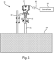
- FIG. 1 is schematic view of a process control or monitoring system in which an isolation manifold embodying the present invention is used.
- Process control or monitoring system 10 includes isolation manifold 12, pressure transmitter 14, impulse line 16, support 18, control or monitoring loop 20, control room 22, and process vessel 24.
- process vessel 24 is illustrated as a tank, it may also be any of a number of process vessels or conduits containing a process fluid, including: process piping, storage tank, heat exchanger, boiler, distillation column, kiln, or reactor.
- isolator manifold 12 is fluidly connected to process vessel 24 by way of impulse line 16, and to pressure transmitter 14.
- Pressure transmitter 14 is held in position by support 18, which may be attached to process vessel 24, as illustrated.
- Control or monitoring loop 20 connects pressure transmitter 14 to control room 22.
- Pressure transmitter 14 includes a pressure sensor and transmitter circuitry for generating an electrical signal based on a sensed pressure of the process fluid. Pressure transmitter 14 also includes other electrical components for transmitting the electrical signal over control or monitoring loop 20 to control room 22 or a local display such as an LCD screen, or both.
- Isolator manifold 12 includes a pressure limiting device that limits the pressure in the isolation manifold by automatically providing a volume into which the trapped process fluid can expand, as discussed with reference to FIG. 2 .
- pressure transmitter 14 is a two-wire transmitter for operating on a 4-20 mA loop.
- control or monitoring loop 20 includes a pair of wires for supplying power to process transmitter 14 from control room 22.
- Control or monitoring loop 20 also enables control room 22 to transmit data to and receive data from pressure transmitter 14.
- Communication over control or monitoring loop 20 can be in the form of an analog current level which varies between 4 and 20 mA, a HART® communication protocol in which digital information is modulated upon a 4-20 mA current, or a Fieldbus or Profibus communication protocol over a digital bus.
- pressure transmitter 14 communicates with control room 22 over a wireless network using a wireless protocol such as, for example, WirelessHART (IEC 62951).
- FIG. 2 is a perspective view of isolation manifold 12 illustrating on embodiment of the present invention.
- Isolation manifold 12 includes manifold body 30, process connection 32, pressure transmitter connection 34, isolation valve 36, bleed valve 38, and pressure limiting device 42.
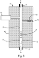
- FIG. 3 is a schematic view of the isolation manifold shown in FIG. 2 . As shown in FIG. 3 , isolation manifold 12 further includes bleed port 40 and passageway 44.
- process connection 32 is at a first end of manifold body 30
- pressure transmitter connection 34 is at a second end of manifold body 30
- passageway 44 fluidly connects process connection 32 to process transmitter connection 34.
- isolation valve 36 may be operated to selectively block passageway 44 to isolate pressure transmitter connection 34 from process connection 32.
- Pressure limiting device 42 is fluidly connected to passageway 44 between isolation valve 36 and process transmitter connection 34.
- Bleed port 40 is fluidly connected to passageway 44 between isolation valve 36 and process transmitter connection 34.
- Bleed valve 38 is fluidly connected to bleed port 40 and may be operated to selectively open bleed port 40.
- bleed valve 38 is operated to close bleed port 40.
- Isolation valve 36 is operated to open passageway 44, so that pressure transmitter 14 senses a process pressure of process vessel 24 by way of impulse line 16 and passageway 44 in isolation manifold 12.
- Pressure limiting device 42 is fluidly connected to passageway 44, but does not typically activate during normal operation because the process pressure of process vessel 24 is typically controlled such that it is well below an overpressure limit for pressure transmitter 14.
- isolation valve 36 When it is desired to take pressure transmitter 14 is out of service, isolation valve 36 is operated to block passageway 44. This isolates process connection 32 from process transmitter connection 34, thus isolating pressure transmitter 14 from impulse line 16 and process vessel 24. Process fluid pressure within passageway 44 may be relieved by operating bleed valve 38 to open bleed port 40.
- process fluid may become trapped within passageway 44 because, for example, bleed valve 38 is inadvertently not operated to open bleed port 40, or bleed port 40 includes a plug (not shown) that is inadvertently not removed.
- Process fluid thus trapped within passageway 44 may increase in volume due to, for example, a temperature change, resulting in an increase in the pressure of the trapped process fluid.
- pressure limiting device 42 automatically operates to prevent a further increase in the trapped process fluid pressure.
- Pressure limiting device 42 limits the pressure in isolation valve by automatically providing a volume into which the trapped process fluid can expand before the trapped process fluid exceeds the overpressure limit for pressure transmitter 14.
- the pressure limiting device 42 is a volume expansion compensator which provides a contained volume into which the trapped process fluid may expand against a known pressure.
- a volume expansion compensator is essentially a pressure containment structure containing within a flexible membrane that separates the process fluid from a volume of pressurized inert gas. By adjusting, or charging, the inert gas volume to a desired pressure, the volume expansion compensator is able to accommodate an increasing volume of process fluid as the process fluid pressure increases above a desired level.
- the flexible membrane is selected such that is it non-reactive with the process fluid and able to remain flexible over an anticipated range of temperatures. Such devices are commercially available and may also be referred to as thermal expansion compensators.
- pressure limiting device 42 may be a pressure relief valve and the trapped process fluid may expand into an uncontained volume ambient to isolation manifold 12, or into a contained volume attached to the outflow of the pressure relief valve.
- pressure limiting device 42 is calibrated to automatically provide pressure relief before the overpressure limit of pressure transmitter 14 is reached, thus protecting pressure transmitter 14 from damage due to the expansion of process fluid trapped within isolation manifold 12.
- Pressure limiting device 42 may also provide some protection of process transmitter 14 from fluid hammer by absorbing some effect of a damaging pressure impulse.
- the pressure impulse resulting from fluid hammer lasts for only a few milliseconds and the automatic operation of pressure limiting device 42 may not be able to fully react in such a short period of time.
- isolation manifold 12 preferably includes pressure snubber 46 within passageway 44.
- Pressure snubber 46 increases flow impedance through isolation manifold 12, reducing the rate at which a pressure impulse can pass through passageway 44 and the magnitude of the pressure impulse.
- Pressure snubber 46 increases the flow impedance through passageway 44, reducing the rate at which a pressure impulse can pass through isolation manifold 12 to pressure transmitter 14, thus reducing the magnitude of the pressure impulse.
- Pressure snubber 46 may be, for example, a porous filter media made of sintered metal or a nozzle that restricts process fluid flow to an orifice having a diameter smaller than passageway 44.
- pressure snubber 46 is disposed in a portion of passageway 44 between process connection 32 and isolation valve 36. While this location facilitates assembly of isolation manifold 12 to include pressure snubber 46, it is understood that embodiments of the present invention include those having pressure snubber 46 anywhere within passageway 44, provided that pressure snubber 46 increases flow impedance between process connection 32 and pressure transmitter connection 34.
- isolation manifold for use with an inline pressure transmitter
- present invention encompasses embodiments of isolation manifolds for use with differential pressure transmitters.
- embodiments above are shown with a bleed valve (sometimes referred to as a two-valve configuration), it is understood that the invention encompasses embodiments including a bleed screw instead of a bleed valve (sometimes referred to as a block-and-bleed configuration).
- Embodiments of the present invention overcome the problem of damage to a pressure transmitter due to expansion of a trapped volume within an attached isolation manifold by including a pressure limiting device in the isolation manifold between an isolation valve and the pressure transmitter.
- the pressure limiting device limits the pressure in the isolation valve by automatically providing a volume into which the trapped process fluid can expand before the trapped process fluid exceeds an overpressure limit for the attached pressure transmitter.
- Isolation manifolds embodying the present invention are easy to install and use, thus no additional training or action is required to provide automatic protection from damage due to trapped process fluid.
- Some embodiments of the present invention also prevent damage to the process transmitter due to fluid hammer by including a pressure snubber within the isolation manifold.
- a pressure snubber increases the flow impedance through the isolation manifold, reducing the rate at which a pressure impulse can pass through the isolation manifold to the pressure transmitter, thus reducing the magnitude of the pressure impulse.
Landscapes
- Engineering & Computer Science (AREA)
- General Engineering & Computer Science (AREA)
- Physics & Mathematics (AREA)
- General Physics & Mathematics (AREA)
- Mechanical Engineering (AREA)
- Measuring Fluid Pressure (AREA)
- Control Of Fluid Pressure (AREA)
Claims (11)
- Collecteur d'isolement (12) destiné à être utilisé avec un transmetteur de pression qui inclut un capteur de pression et un circuit de transmetteur pour générer un signal électrique sur la base d'une pression détectée d'un fluide de processus, le collecteur d'isolement comprenant :un corps de collecteur (30) ;un raccord de processus (32) à une première extrémité du corps de collecteur (30) pour connecter fluidiquement le collecteur d'isolement (12) à un récipient de processus (24) ou à un conduit contenant un fluide de processus ;un raccord de transmetteur de pression (34) à une deuxième extrémité du corps de collecteur (30) pour connecter fluidiquement le collecteur d'isolement (12) au transmetteur de pression (14) ;un passage (44) à travers le corps de collecteur (30) connectant fluidiquement le raccord de processus (32) au raccord de transmetteur de pression (34) ;une vanne d'isolement (36) actionnable pour bloquer sélectivement le passage (44) pour isoler le raccord de processus (32) du raccord de transmetteur de pression (34) ; etun dispositif limiteur de pression (42) connecté fluidiquement au passage (44) entre la vanne d'isolement (36) et le raccord de transmetteur de pression (34), sachant que le dispositif limiteur de pression est un compensateur à dilatation de volume,sachant que le compensateur à dilatation de volume comprend une membrane flexible qui sépare le fluide de processus d'un volume de gaz inerte sous pression.
- Le collecteur de la revendication 1, comprenant en outre :
un amortisseur de pression (46) à l'intérieur du passage (44) pour augmenter une impédance de flux du passage (44). - Le collecteur de la revendication 2, sachant que l'amortisseur de pression (46) inclut soit :a) un support de filtre poreux composé de métal fritté, soitb) une tuyère qui restreint un flux de fluide de processus à un orifice ayant un diamètre plus petit que le passage (44).
- Le collecteur de la revendication 1, comprenant en outre :
un orifice de purge (40) connecté fluidiquement au passage (44) entre la vanne d'isolement (36) et le raccord de transmetteur de pression (34). - Le collecteur de la revendication 4, comprenant en outre :
une vis de purge connectée fluidiquement à l'orifice de purge (40) et actionnable pour ouvrir sélectivement l'orifice de purge (40). - Le collecteur de la revendication 4, comprenant en outre :
une vanne de purge (38) connectée fluidiquement à l'orifice de purge (40) et actionnable pour ouvrir sélectivement l'orifice de purge (40). - Système de mesure de pression comprenant :un transmetteur de pression (14) ; etle collecteur d'isolement (12) de la revendication 1 connectant fluidiquement le transmetteur de pression (14) à un récipient de processus (24) ou à un conduit contenant un fluide de processus.
- Le système de la revendication 7, sachant que le collecteur inclut en outre :
un amortisseur de pression (46) à l'intérieur du passage (44) pour augmenter une impédance de flux du passage (44). - Le système de la revendication 7, sachant que le collecteur inclut en outre :
un orifice de purge (40) connecté fluidiquement au passage (44) entre la vanne d'isolement (36) et le raccord de transmetteur de pression (34). - Le système de la revendication 9, sachant que le collecteur inclut en outre :
une vis de purge connectée fluidiquement à l'orifice de purge (40) et actionnable pour ouvrir sélectivement l'orifice de purge (40). - Le système de la revendication 9, sachant que le collecteur inclut en outre :
une vanne de purge (38) connectée fluidiquement à l'orifice de purge (40) et actionnable pour ouvrir sélectivement l'orifice de purge (40).
Applications Claiming Priority (2)
| Application Number | Priority Date | Filing Date | Title |
|---|---|---|---|
| US14/037,856 US9086167B2 (en) | 2013-09-26 | 2013-09-26 | Pressure isolation manifold |
| PCT/US2014/057792 WO2015048500A1 (fr) | 2013-09-26 | 2014-09-26 | Collecteur d'isolement de pression |
Publications (3)
| Publication Number | Publication Date |
|---|---|
| EP3049711A1 EP3049711A1 (fr) | 2016-08-03 |
| EP3049711A4 EP3049711A4 (fr) | 2017-05-17 |
| EP3049711B1 true EP3049711B1 (fr) | 2020-08-05 |
Family
ID=51344911
Family Applications (1)
| Application Number | Title | Priority Date | Filing Date |
|---|---|---|---|
| EP14847191.5A Active EP3049711B1 (fr) | 2013-09-26 | 2014-09-26 | Collecteur d'isolement de pression |
Country Status (6)
| Country | Link |
|---|---|
| US (1) | US9086167B2 (fr) |
| EP (1) | EP3049711B1 (fr) |
| JP (1) | JP6461112B2 (fr) |
| CN (2) | CN203745125U (fr) |
| CA (1) | CA2920223A1 (fr) |
| WO (1) | WO2015048500A1 (fr) |
Families Citing this family (9)
| Publication number | Priority date | Publication date | Assignee | Title |
|---|---|---|---|---|
| US9086167B2 (en) * | 2013-09-26 | 2015-07-21 | Rosemount Inc. | Pressure isolation manifold |
| US10655752B2 (en) | 2017-03-01 | 2020-05-19 | Rosemount Inc. | Internal valve manifold |
| CN106908354A (zh) * | 2017-03-09 | 2017-06-30 | 陕西科技大学 | 一种滑溜水压裂液摩阻测试装置及其测试方法 |
| CN108106770B (zh) * | 2017-11-10 | 2019-05-03 | 华中科技大学 | 一种用于离心铸造物理模拟的充型流体压力在线测量系统 |
| US20190323924A1 (en) * | 2018-04-20 | 2019-10-24 | Kai-Ee Inc. | Testing device for vehicles |
| US11428593B2 (en) * | 2019-11-20 | 2022-08-30 | Honeywell International Inc. | Methods and apparatuses for providing freeze resistant sensing assembly |
| CN111174968A (zh) * | 2020-03-03 | 2020-05-19 | 浙江奥新仪表有限公司 | 一种超高压高精度压力变送器 |
| CN113339553B (zh) * | 2021-04-30 | 2023-03-10 | 中国东方电气集团有限公司 | 一种爆破片安全装置 |
| CN116919791A (zh) * | 2023-08-10 | 2023-10-24 | 逸航汽车零部件无锡有限公司 | 一种按摩系统及包含其的汽车按摩座椅 |
Family Cites Families (17)
| Publication number | Priority date | Publication date | Assignee | Title |
|---|---|---|---|---|
| US3145733A (en) * | 1960-07-07 | 1964-08-25 | Bastian Blessing Co | Swivel ring valve |
| US3207179A (en) * | 1962-11-23 | 1965-09-21 | Schulz Tool & Mfg Co | Gauge saver |
| JPS5057027U (fr) * | 1974-05-27 | 1975-05-28 | ||
| US4076211A (en) * | 1975-10-14 | 1978-02-28 | Control Devices, Incorporated | Ball valve |
| US4120206A (en) | 1977-01-17 | 1978-10-17 | Rosemount Inc. | Differential pressure sensor capsule with low acceleration sensitivity |
| JPS5829865B2 (ja) * | 1977-06-07 | 1983-06-25 | テイサン株式会社 | ブルドン管圧力計の安全装置 |
| US4616677A (en) * | 1983-03-14 | 1986-10-14 | Control Devices, Incorporated | Manifold fitting for a compressed air tank |
| US4570677A (en) * | 1983-03-31 | 1986-02-18 | Paratech Incorporated | Unitary multiple control valve assembly |
| US4644972A (en) * | 1985-07-12 | 1987-02-24 | Precision Plumbing Products, Inc. | Floating seal valve assembly |
| US5583294A (en) * | 1994-08-22 | 1996-12-10 | The Foxboro Company | Differential pressure transmitter having an integral flame arresting body and overrange diaphragm |
| JP3476199B2 (ja) | 1995-04-28 | 2003-12-10 | ローズマウント インコーポレイテッド | 高圧隔離マウント組立体を有する圧力トランスミッタ |
| DK0915326T3 (da) | 1997-10-10 | 2002-03-25 | Wika Alexander Wiegand Gmbh | Fremgangsmåde til fremstilling af en trykmåletransducer samt trykmåletransducer |
| AU2002234163A1 (en) | 2000-10-24 | 2002-05-06 | Rosemount, Inc. | Process connection for in-line pressure transmitter |
| US7231831B1 (en) | 2006-01-17 | 2007-06-19 | Noshok, Inc. | Manifold valve and pressure transducer assembly |
| GB2457473A (en) | 2008-02-14 | 2009-08-19 | Bifold Fluidpower Ltd | Isolation valve manifold |
| BR112012030042B1 (pt) | 2010-05-26 | 2020-09-29 | Petrolvalves S.P.A | Dispositivo de alívio de pressão inteligente para uma válvula de isolamento duplo |
| US9086167B2 (en) * | 2013-09-26 | 2015-07-21 | Rosemount Inc. | Pressure isolation manifold |
-
2013
- 2013-09-26 US US14/037,856 patent/US9086167B2/en active Active
-
2014
- 2014-01-15 CN CN201420023710.1U patent/CN203745125U/zh not_active Expired - Fee Related
- 2014-01-15 CN CN201410018377.XA patent/CN104515642B/zh active Active
- 2014-09-26 CA CA2920223A patent/CA2920223A1/fr not_active Abandoned
- 2014-09-26 WO PCT/US2014/057792 patent/WO2015048500A1/fr not_active Ceased
- 2014-09-26 JP JP2016517336A patent/JP6461112B2/ja active Active
- 2014-09-26 EP EP14847191.5A patent/EP3049711B1/fr active Active
Non-Patent Citations (1)
| Title |
|---|
| None * |
Also Published As
| Publication number | Publication date |
|---|---|
| WO2015048500A1 (fr) | 2015-04-02 |
| JP6461112B2 (ja) | 2019-01-30 |
| EP3049711A1 (fr) | 2016-08-03 |
| JP2016532851A (ja) | 2016-10-20 |
| CA2920223A1 (fr) | 2015-04-02 |
| CN104515642B (zh) | 2019-07-23 |
| US20150083245A1 (en) | 2015-03-26 |
| US9086167B2 (en) | 2015-07-21 |
| CN104515642A (zh) | 2015-04-15 |
| CN203745125U (zh) | 2014-07-30 |
| EP3049711A4 (fr) | 2017-05-17 |
Similar Documents
| Publication | Publication Date | Title |
|---|---|---|
| EP3049711B1 (fr) | Collecteur d'isolement de pression | |
| EP2132532B1 (fr) | Module de capteur de pression differentielle sans brides pour systemes de commande de procede industriel | |
| CA2971269C (fr) | Vannes d'installations d'extinction d'incendie et installations d'extinction d'incendie equipees de ces vannes | |
| EP1214540B1 (fr) | Soupape pour bouteilles a gaz haute pression | |
| CN102883782B (zh) | 阀门 | |
| AU2008266600B2 (en) | Methods and apparatus to determine a position of a valve | |
| JP4975040B2 (ja) | 過剰圧力ベントを備えるプロセストランスミッタ | |
| EP1328784B1 (fr) | Transmetteur de pression en ligne | |
| EP3011293B1 (fr) | Sonde récupérable et méthode correspondante | |
| CN104048796B (zh) | 用于压力变送器的可独立更换的密封系统 | |
| US7251985B2 (en) | Safety module and measuring arrangement with safety module | |
| CN100494940C (zh) | 用于测量容置在箱中的或流经导管的流体的压力的装置 | |
| KR20180002187A (ko) | 커넥팅부가 구비된 소방용 버터플라이밸브 | |
| CN220137588U (zh) | 压力控制装置及压力控制系统 | |
| US20190234822A1 (en) | Hot-swappable access/retrieval plug for high pressure fluid systems | |
| CN119597036A (zh) | 具有动态参考压力的控制系统 | |
| KR20080066657A (ko) | 안테나 모듈 |
Legal Events
| Date | Code | Title | Description |
|---|---|---|---|
| PUAI | Public reference made under article 153(3) epc to a published international application that has entered the european phase |
Free format text: ORIGINAL CODE: 0009012 |
|
| 17P | Request for examination filed |
Effective date: 20160211 |
|
| AK | Designated contracting states |
Kind code of ref document: A1 Designated state(s): AL AT BE BG CH CY CZ DE DK EE ES FI FR GB GR HR HU IE IS IT LI LT LU LV MC MK MT NL NO PL PT RO RS SE SI SK SM TR |
|
| AX | Request for extension of the european patent |
Extension state: BA ME |
|
| DAX | Request for extension of the european patent (deleted) | ||
| A4 | Supplementary search report drawn up and despatched |
Effective date: 20170420 |
|
| RIC1 | Information provided on ipc code assigned before grant |
Ipc: G01L 19/06 20060101ALI20170412BHEP Ipc: F17D 5/00 20060101ALI20170412BHEP Ipc: G01L 19/00 20060101ALI20170412BHEP Ipc: F17C 13/02 20060101AFI20170412BHEP |
|
| STAA | Information on the status of an ep patent application or granted ep patent |
Free format text: STATUS: EXAMINATION IS IN PROGRESS |
|
| 17Q | First examination report despatched |
Effective date: 20180416 |
|
| GRAP | Despatch of communication of intention to grant a patent |
Free format text: ORIGINAL CODE: EPIDOSNIGR1 |
|
| STAA | Information on the status of an ep patent application or granted ep patent |
Free format text: STATUS: GRANT OF PATENT IS INTENDED |
|
| INTG | Intention to grant announced |
Effective date: 20200218 |
|
| GRAS | Grant fee paid |
Free format text: ORIGINAL CODE: EPIDOSNIGR3 |
|
| GRAA | (expected) grant |
Free format text: ORIGINAL CODE: 0009210 |
|
| STAA | Information on the status of an ep patent application or granted ep patent |
Free format text: STATUS: THE PATENT HAS BEEN GRANTED |
|
| AK | Designated contracting states |
Kind code of ref document: B1 Designated state(s): AL AT BE BG CH CY CZ DE DK EE ES FI FR GB GR HR HU IE IS IT LI LT LU LV MC MK MT NL NO PL PT RO RS SE SI SK SM TR |
|
| REG | Reference to a national code |
Ref country code: GB Ref legal event code: FG4D |
|
| REG | Reference to a national code |
Ref country code: CH Ref legal event code: EP Ref country code: CH Ref legal event code: NV Representative=s name: FELBER UND PARTNER AG, CH |
|
| REG | Reference to a national code |
Ref country code: AT Ref legal event code: REF Ref document number: 1299190 Country of ref document: AT Kind code of ref document: T Effective date: 20200815 |
|
| REG | Reference to a national code |
Ref country code: DE Ref legal event code: R096 Ref document number: 602014068710 Country of ref document: DE |
|
| REG | Reference to a national code |
Ref country code: IE Ref legal event code: FG4D |
|
| PGFP | Annual fee paid to national office [announced via postgrant information from national office to epo] |
Ref country code: CH Payment date: 20200917 Year of fee payment: 7 |
|
| REG | Reference to a national code |
Ref country code: LT Ref legal event code: MG4D |
|
| REG | Reference to a national code |
Ref country code: NL Ref legal event code: MP Effective date: 20200805 |
|
| REG | Reference to a national code |
Ref country code: AT Ref legal event code: MK05 Ref document number: 1299190 Country of ref document: AT Kind code of ref document: T Effective date: 20200805 |
|
| PG25 | Lapsed in a contracting state [announced via postgrant information from national office to epo] |
Ref country code: FI Free format text: LAPSE BECAUSE OF FAILURE TO SUBMIT A TRANSLATION OF THE DESCRIPTION OR TO PAY THE FEE WITHIN THE PRESCRIBED TIME-LIMIT Effective date: 20200805 Ref country code: ES Free format text: LAPSE BECAUSE OF FAILURE TO SUBMIT A TRANSLATION OF THE DESCRIPTION OR TO PAY THE FEE WITHIN THE PRESCRIBED TIME-LIMIT Effective date: 20200805 Ref country code: PT Free format text: LAPSE BECAUSE OF FAILURE TO SUBMIT A TRANSLATION OF THE DESCRIPTION OR TO PAY THE FEE WITHIN THE PRESCRIBED TIME-LIMIT Effective date: 20201207 Ref country code: HR Free format text: LAPSE BECAUSE OF FAILURE TO SUBMIT A TRANSLATION OF THE DESCRIPTION OR TO PAY THE FEE WITHIN THE PRESCRIBED TIME-LIMIT Effective date: 20200805 Ref country code: SE Free format text: LAPSE BECAUSE OF FAILURE TO SUBMIT A TRANSLATION OF THE DESCRIPTION OR TO PAY THE FEE WITHIN THE PRESCRIBED TIME-LIMIT Effective date: 20200805 Ref country code: LT Free format text: LAPSE BECAUSE OF FAILURE TO SUBMIT A TRANSLATION OF THE DESCRIPTION OR TO PAY THE FEE WITHIN THE PRESCRIBED TIME-LIMIT Effective date: 20200805 Ref country code: BG Free format text: LAPSE BECAUSE OF FAILURE TO SUBMIT A TRANSLATION OF THE DESCRIPTION OR TO PAY THE FEE WITHIN THE PRESCRIBED TIME-LIMIT Effective date: 20201105 Ref country code: GR Free format text: LAPSE BECAUSE OF FAILURE TO SUBMIT A TRANSLATION OF THE DESCRIPTION OR TO PAY THE FEE WITHIN THE PRESCRIBED TIME-LIMIT Effective date: 20201106 Ref country code: NO Free format text: LAPSE BECAUSE OF FAILURE TO SUBMIT A TRANSLATION OF THE DESCRIPTION OR TO PAY THE FEE WITHIN THE PRESCRIBED TIME-LIMIT Effective date: 20201105 Ref country code: AT Free format text: LAPSE BECAUSE OF FAILURE TO SUBMIT A TRANSLATION OF THE DESCRIPTION OR TO PAY THE FEE WITHIN THE PRESCRIBED TIME-LIMIT Effective date: 20200805 |
|
| PG25 | Lapsed in a contracting state [announced via postgrant information from national office to epo] |
Ref country code: LV Free format text: LAPSE BECAUSE OF FAILURE TO SUBMIT A TRANSLATION OF THE DESCRIPTION OR TO PAY THE FEE WITHIN THE PRESCRIBED TIME-LIMIT Effective date: 20200805 Ref country code: NL Free format text: LAPSE BECAUSE OF FAILURE TO SUBMIT A TRANSLATION OF THE DESCRIPTION OR TO PAY THE FEE WITHIN THE PRESCRIBED TIME-LIMIT Effective date: 20200805 Ref country code: RS Free format text: LAPSE BECAUSE OF FAILURE TO SUBMIT A TRANSLATION OF THE DESCRIPTION OR TO PAY THE FEE WITHIN THE PRESCRIBED TIME-LIMIT Effective date: 20200805 Ref country code: PL Free format text: LAPSE BECAUSE OF FAILURE TO SUBMIT A TRANSLATION OF THE DESCRIPTION OR TO PAY THE FEE WITHIN THE PRESCRIBED TIME-LIMIT Effective date: 20200805 Ref country code: IS Free format text: LAPSE BECAUSE OF FAILURE TO SUBMIT A TRANSLATION OF THE DESCRIPTION OR TO PAY THE FEE WITHIN THE PRESCRIBED TIME-LIMIT Effective date: 20201205 |
|
| PG25 | Lapsed in a contracting state [announced via postgrant information from national office to epo] |
Ref country code: CZ Free format text: LAPSE BECAUSE OF FAILURE TO SUBMIT A TRANSLATION OF THE DESCRIPTION OR TO PAY THE FEE WITHIN THE PRESCRIBED TIME-LIMIT Effective date: 20200805 Ref country code: DK Free format text: LAPSE BECAUSE OF FAILURE TO SUBMIT A TRANSLATION OF THE DESCRIPTION OR TO PAY THE FEE WITHIN THE PRESCRIBED TIME-LIMIT Effective date: 20200805 Ref country code: RO Free format text: LAPSE BECAUSE OF FAILURE TO SUBMIT A TRANSLATION OF THE DESCRIPTION OR TO PAY THE FEE WITHIN THE PRESCRIBED TIME-LIMIT Effective date: 20200805 Ref country code: SM Free format text: LAPSE BECAUSE OF FAILURE TO SUBMIT A TRANSLATION OF THE DESCRIPTION OR TO PAY THE FEE WITHIN THE PRESCRIBED TIME-LIMIT Effective date: 20200805 Ref country code: EE Free format text: LAPSE BECAUSE OF FAILURE TO SUBMIT A TRANSLATION OF THE DESCRIPTION OR TO PAY THE FEE WITHIN THE PRESCRIBED TIME-LIMIT Effective date: 20200805 |
|
| REG | Reference to a national code |
Ref country code: DE Ref legal event code: R097 Ref document number: 602014068710 Country of ref document: DE |
|
| PG25 | Lapsed in a contracting state [announced via postgrant information from national office to epo] |
Ref country code: MC Free format text: LAPSE BECAUSE OF FAILURE TO SUBMIT A TRANSLATION OF THE DESCRIPTION OR TO PAY THE FEE WITHIN THE PRESCRIBED TIME-LIMIT Effective date: 20200805 Ref country code: AL Free format text: LAPSE BECAUSE OF FAILURE TO SUBMIT A TRANSLATION OF THE DESCRIPTION OR TO PAY THE FEE WITHIN THE PRESCRIBED TIME-LIMIT Effective date: 20200805 |
|
| PLBE | No opposition filed within time limit |
Free format text: ORIGINAL CODE: 0009261 |
|
| STAA | Information on the status of an ep patent application or granted ep patent |
Free format text: STATUS: NO OPPOSITION FILED WITHIN TIME LIMIT |
|
| REG | Reference to a national code |
Ref country code: BE Ref legal event code: MM Effective date: 20200930 |
|
| PG25 | Lapsed in a contracting state [announced via postgrant information from national office to epo] |
Ref country code: SK Free format text: LAPSE BECAUSE OF FAILURE TO SUBMIT A TRANSLATION OF THE DESCRIPTION OR TO PAY THE FEE WITHIN THE PRESCRIBED TIME-LIMIT Effective date: 20200805 Ref country code: LU Free format text: LAPSE BECAUSE OF NON-PAYMENT OF DUE FEES Effective date: 20200926 |
|
| 26N | No opposition filed |
Effective date: 20210507 |
|
| GBPC | Gb: european patent ceased through non-payment of renewal fee |
Effective date: 20201105 |
|
| PG25 | Lapsed in a contracting state [announced via postgrant information from national office to epo] |
Ref country code: IT Free format text: LAPSE BECAUSE OF FAILURE TO SUBMIT A TRANSLATION OF THE DESCRIPTION OR TO PAY THE FEE WITHIN THE PRESCRIBED TIME-LIMIT Effective date: 20200805 Ref country code: FR Free format text: LAPSE BECAUSE OF NON-PAYMENT OF DUE FEES Effective date: 20201005 |
|
| PG25 | Lapsed in a contracting state [announced via postgrant information from national office to epo] |
Ref country code: IE Free format text: LAPSE BECAUSE OF NON-PAYMENT OF DUE FEES Effective date: 20200926 Ref country code: SI Free format text: LAPSE BECAUSE OF FAILURE TO SUBMIT A TRANSLATION OF THE DESCRIPTION OR TO PAY THE FEE WITHIN THE PRESCRIBED TIME-LIMIT Effective date: 20200805 Ref country code: BE Free format text: LAPSE BECAUSE OF NON-PAYMENT OF DUE FEES Effective date: 20200930 |
|
| PG25 | Lapsed in a contracting state [announced via postgrant information from national office to epo] |
Ref country code: GB Free format text: LAPSE BECAUSE OF NON-PAYMENT OF DUE FEES Effective date: 20201105 |
|
| REG | Reference to a national code |
Ref country code: CH Ref legal event code: PL |
|
| PG25 | Lapsed in a contracting state [announced via postgrant information from national office to epo] |
Ref country code: IS Free format text: LAPSE BECAUSE OF FAILURE TO SUBMIT A TRANSLATION OF THE DESCRIPTION OR TO PAY THE FEE WITHIN THE PRESCRIBED TIME-LIMIT Effective date: 20201205 Ref country code: TR Free format text: LAPSE BECAUSE OF FAILURE TO SUBMIT A TRANSLATION OF THE DESCRIPTION OR TO PAY THE FEE WITHIN THE PRESCRIBED TIME-LIMIT Effective date: 20200805 Ref country code: MT Free format text: LAPSE BECAUSE OF FAILURE TO SUBMIT A TRANSLATION OF THE DESCRIPTION OR TO PAY THE FEE WITHIN THE PRESCRIBED TIME-LIMIT Effective date: 20200805 Ref country code: CY Free format text: LAPSE BECAUSE OF FAILURE TO SUBMIT A TRANSLATION OF THE DESCRIPTION OR TO PAY THE FEE WITHIN THE PRESCRIBED TIME-LIMIT Effective date: 20200805 |
|
| PG25 | Lapsed in a contracting state [announced via postgrant information from national office to epo] |
Ref country code: MK Free format text: LAPSE BECAUSE OF FAILURE TO SUBMIT A TRANSLATION OF THE DESCRIPTION OR TO PAY THE FEE WITHIN THE PRESCRIBED TIME-LIMIT Effective date: 20200805 |
|
| PG25 | Lapsed in a contracting state [announced via postgrant information from national office to epo] |
Ref country code: LI Free format text: LAPSE BECAUSE OF NON-PAYMENT OF DUE FEES Effective date: 20210930 Ref country code: CH Free format text: LAPSE BECAUSE OF NON-PAYMENT OF DUE FEES Effective date: 20210930 |
|
| P01 | Opt-out of the competence of the unified patent court (upc) registered |
Effective date: 20231218 |
|
| PGFP | Annual fee paid to national office [announced via postgrant information from national office to epo] |
Ref country code: DE Payment date: 20250820 Year of fee payment: 12 |