EP3054800B1 - Procédés et appareils de manipulation de température - Google Patents
Procédés et appareils de manipulation de température Download PDFInfo
- Publication number
- EP3054800B1 EP3054800B1 EP14851667.7A EP14851667A EP3054800B1 EP 3054800 B1 EP3054800 B1 EP 3054800B1 EP 14851667 A EP14851667 A EP 14851667A EP 3054800 B1 EP3054800 B1 EP 3054800B1
- Authority
- EP
- European Patent Office
- Prior art keywords
- temperature
- thermoelectric material
- thermal
- less
- adjacent
- Prior art date
- Legal status (The legal status is an assumption and is not a legal conclusion. Google has not performed a legal analysis and makes no representation as to the accuracy of the status listed.)
- Active
Links
Images



Classifications
-
- A—HUMAN NECESSITIES
- A44—HABERDASHERY; JEWELLERY
- A44C—PERSONAL ADORNMENTS, e.g. JEWELLERY; COINS
- A44C5/00—Bracelets; Wrist-watch straps; Fastenings for bracelets or wrist-watch straps
- A44C5/0007—Bracelets specially adapted for other functions or with means for attaching other articles
-
- A—HUMAN NECESSITIES
- A61—MEDICAL OR VETERINARY SCIENCE; HYGIENE
- A61F—FILTERS IMPLANTABLE INTO BLOOD VESSELS; PROSTHESES; DEVICES PROVIDING PATENCY TO, OR PREVENTING COLLAPSING OF, TUBULAR STRUCTURES OF THE BODY, e.g. STENTS; ORTHOPAEDIC, NURSING OR CONTRACEPTIVE DEVICES; FOMENTATION; TREATMENT OR PROTECTION OF EYES OR EARS; BANDAGES, DRESSINGS OR ABSORBENT PADS; FIRST-AID KITS
- A61F7/00—Heating or cooling appliances for medical or therapeutic treatment of the human body
- A61F7/007—Heating or cooling appliances for medical or therapeutic treatment of the human body characterised by electric heating
-
- G—PHYSICS
- G01—MEASURING; TESTING
- G01K—MEASURING TEMPERATURE; MEASURING QUANTITY OF HEAT; THERMALLY-SENSITIVE ELEMENTS NOT OTHERWISE PROVIDED FOR
- G01K1/00—Details of thermometers not specially adapted for particular types of thermometer
- G01K1/14—Supports; Fastening devices; Arrangements for mounting thermometers in particular locations
- G01K1/143—Supports; Fastening devices; Arrangements for mounting thermometers in particular locations for measuring surface temperatures
-
- G—PHYSICS
- G01—MEASURING; TESTING
- G01K—MEASURING TEMPERATURE; MEASURING QUANTITY OF HEAT; THERMALLY-SENSITIVE ELEMENTS NOT OTHERWISE PROVIDED FOR
- G01K13/00—Thermometers specially adapted for specific purposes
- G01K13/20—Clinical contact thermometers for use with humans or animals
-
- A—HUMAN NECESSITIES
- A41—WEARING APPAREL
- A41D—OUTERWEAR; PROTECTIVE GARMENTS; ACCESSORIES
- A41D13/00—Professional, industrial or sporting protective garments, e.g. surgeons' gowns or garments protecting against blows or punches
- A41D13/002—Professional, industrial or sporting protective garments, e.g. surgeons' gowns or garments protecting against blows or punches with controlled internal environment
- A41D13/005—Professional, industrial or sporting protective garments, e.g. surgeons' gowns or garments protecting against blows or punches with controlled internal environment with controlled temperature
-
- A—HUMAN NECESSITIES
- A61—MEDICAL OR VETERINARY SCIENCE; HYGIENE
- A61F—FILTERS IMPLANTABLE INTO BLOOD VESSELS; PROSTHESES; DEVICES PROVIDING PATENCY TO, OR PREVENTING COLLAPSING OF, TUBULAR STRUCTURES OF THE BODY, e.g. STENTS; ORTHOPAEDIC, NURSING OR CONTRACEPTIVE DEVICES; FOMENTATION; TREATMENT OR PROTECTION OF EYES OR EARS; BANDAGES, DRESSINGS OR ABSORBENT PADS; FIRST-AID KITS
- A61F7/00—Heating or cooling appliances for medical or therapeutic treatment of the human body
- A61F2007/0001—Body part
- A61F2007/0029—Arm or parts thereof
- A61F2007/0035—Wrist
-
- A—HUMAN NECESSITIES
- A61—MEDICAL OR VETERINARY SCIENCE; HYGIENE
- A61F—FILTERS IMPLANTABLE INTO BLOOD VESSELS; PROSTHESES; DEVICES PROVIDING PATENCY TO, OR PREVENTING COLLAPSING OF, TUBULAR STRUCTURES OF THE BODY, e.g. STENTS; ORTHOPAEDIC, NURSING OR CONTRACEPTIVE DEVICES; FOMENTATION; TREATMENT OR PROTECTION OF EYES OR EARS; BANDAGES, DRESSINGS OR ABSORBENT PADS; FIRST-AID KITS
- A61F7/00—Heating or cooling appliances for medical or therapeutic treatment of the human body
- A61F7/007—Heating or cooling appliances for medical or therapeutic treatment of the human body characterised by electric heating
- A61F2007/0075—Heating or cooling appliances for medical or therapeutic treatment of the human body characterised by electric heating using a Peltier element, e.g. near the spot to be heated or cooled
-
- A—HUMAN NECESSITIES
- A61—MEDICAL OR VETERINARY SCIENCE; HYGIENE
- A61F—FILTERS IMPLANTABLE INTO BLOOD VESSELS; PROSTHESES; DEVICES PROVIDING PATENCY TO, OR PREVENTING COLLAPSING OF, TUBULAR STRUCTURES OF THE BODY, e.g. STENTS; ORTHOPAEDIC, NURSING OR CONTRACEPTIVE DEVICES; FOMENTATION; TREATMENT OR PROTECTION OF EYES OR EARS; BANDAGES, DRESSINGS OR ABSORBENT PADS; FIRST-AID KITS
- A61F7/00—Heating or cooling appliances for medical or therapeutic treatment of the human body
- A61F2007/0093—Heating or cooling appliances for medical or therapeutic treatment of the human body programmed
-
- A—HUMAN NECESSITIES
- A61—MEDICAL OR VETERINARY SCIENCE; HYGIENE
- A61F—FILTERS IMPLANTABLE INTO BLOOD VESSELS; PROSTHESES; DEVICES PROVIDING PATENCY TO, OR PREVENTING COLLAPSING OF, TUBULAR STRUCTURES OF THE BODY, e.g. STENTS; ORTHOPAEDIC, NURSING OR CONTRACEPTIVE DEVICES; FOMENTATION; TREATMENT OR PROTECTION OF EYES OR EARS; BANDAGES, DRESSINGS OR ABSORBENT PADS; FIRST-AID KITS
- A61F7/00—Heating or cooling appliances for medical or therapeutic treatment of the human body
- A61F7/02—Compresses or poultices for effecting heating or cooling
- A61F2007/0295—Compresses or poultices for effecting heating or cooling for heating or cooling or use at more than one temperature
- A61F2007/0296—Intervals of heating alternated with intervals of cooling
Definitions
- the present disclosure relates generally to methods and apparatuses for manipulating temperature of a surface.
- HVAC heating, ventilation and air conditioning
- Existing wearable devices for thermal regulation are generally passive in that they do not generate or absorb heat but merely serve to insulate the wearer from the outside temperature.
- active wearable devices including watches, accelerometers, motion sensors, etc.
- US 5 746 702 A discloses a device for local massage of the skin.
- the device comprises identical massaging heads, each of which consists of the following: heating elements which are in contact with a thermal contact plate; a heat dissipation system designed, for example, in the form of an air radiator; a housing with a convex spherical surface and a holder made up of the plates with an aperture whose wall has a spherical concave surface, the aperture forming an articulated joint with the surface and thereby ensuring close contact throughout the massage session between the thermal contact plate and the area being massaged.
- the device is provided with an automatic contrasting thermocycling unit consisting of a voltage stabilizer and a pulse generator connected in series, the switching component being connected between the direct current source and the heating elements in the massaging heads.
- the thermal contact plate in contact with the massaged area is periodically cooled and heated by changing the direction of current passing through the heating elements.
- the clamp units are designed preferably in the form of a headpiece consisting of arched spring units whose end sections fit into slots in the holder, thereby allowing the massaging heads to be moved along the clamp units.
- US 2010/198318 A1 teaches neurophysiological activation by vestibular or cranial nerve stimulation, where a method of treating a disorder may include positioning a thermoelectric device in the ear canal of a subject and activating the thermoelectric device to deliver caloric vestibular stimulation and/or cranial nerve stimulation effective to treat the disorder.
- US 8 397 518 B1 provides a device for and method of heating or cooling a portion of a body of a user.
- the device includes a thermoelectric module, a heat sink thermally coupled to the thermoelectric module, a wetting material in thermal communication with the heat sink, and a controller for cycling the thermoelectric module in accordance with a duty cycle.
- a method of heating or cooling a portion of a body of a user is provided. The method includes cycling electrical power to a thermoelectric module at a duty cycle, transferring heat from the thermoelectric module to a heat sink, and evaporating a liquid from a wetted material disposed on the heat sink.
- US 6 739 138 B2 discloses a heating and cooling apparatus to be applied to an object to control its temperature, in which a number of thermoelectric modules are adapted to be positioned in contact with the object in a pattern and a voltage source is adapted to apply a voltage to the thermoelectric modules to cause a temperature change in each thermoelectric module so as to control the temperature of the object in accordance with the pattern and with the voltage applied to thermoelectric modules.
- EP 1 737 052 A1 teaches a heat adjustment device which can be mounted in clothes. After the temperature variation is conducted by the thermoelectric chips to the heat conductive substrate, a corresponding temperature variation is produced on the heat conductive substrate, so that the area of the temperature variation is increased and the temperature is uniformly distributed on the heat conductive substrate.
- US 2009/221943 A1 teaches devices and methods for treating restless leg syndrome.
- a device for manipulating a temperature of a surface includes at least one thermoelectric material constructed and arranged to be disposed adjacent the surface.
- the device also includes a controller in electrical communication with the at least one thermoelectric material, the controller configured to cause the at least one thermoelectric material to generate a thermal pulse at a region of the at least one thermoelectric material adjacent the surface, the thermal pulse including a first temperature adjustment at the region of the at least one thermoelectric material adjacent the surface from a first temperature to a second temperature at a first average rate of between about 0.1°C/sec and about 10.0°C/sec, and a second temperature adjustment at the region of the at least one thermoelectric material adjacent the surface from the second temperature to a third temperature at a second average rate of between about 0.1°C/sec and about 10.0°C/sec, wherein a difference in magnitude between the first temperature and the third temperature is less than 25% of a difference in magnitude between the first temperature and the second temperature.
- a method for manipulating a temperature of a surface includes positioning a region of at least one thermoelectric material adjacent to the surface; and generating a thermal pulse at the region of the at least one thermoelectric material adjacent the surface.
- Generating the thermal pulse may include adjusting temperature at the region of the at least one thermoelectric material adjacent the surface from a first temperature to a second temperature at a first average rate of between about 0.1°C/sec and about 10.0°C/sec, and adjusting temperature at the region of the at least one thermoelectric material adjacent the surface from the second temperature to a third temperature at a second average rate of between about 0.1°C/sec and about 10.0°C/sec, wherein a difference in magnitude between the first temperature and the third temperature is less than 25% of a difference in magnitude between the first temperature and the second temperature.
- a device for manipulating a temperature of a surface includes a thermal adjustment apparatus constructed and arranged to be disposed adjacent the surface, the thermal adjustment apparatus configured to generate a thermal pulse over a time period of less than 120 seconds at a region of the temperature adjustment apparatus adjacent the surface, the thermal pulse including a first temperature adjustment at the region of the thermal adjustment apparatus adjacent the surface from a first temperature to a second temperature at a first average rate of between about 0.1°C/sec and about 10.0°C/sec, and a second temperature adjustment at the region of the thermal adjustment apparatus adjacent the surface from the second temperature to a third temperature at a second average rate of between about 0.1°C/sec and about 10.0°C/sec, wherein a difference in magnitude between the first temperature and the third temperature is less than 25% of a difference in magnitude between the first temperature and the second temperature, and a magnitude of the first average rate is greater than a magnitude of the second average rate.
- a method for manipulating a temperature of a surface includes positioning a region of a thermal adjustment apparatus adjacent to the surface; and generating a thermal pulse over a time period of less than 120 seconds at the region of the thermal adjustment apparatus adjacent the surface.
- Generating the thermal pulse may include adjusting temperature at the region of the thermal adjustment apparatus adjacent the surface from a first temperature to a second temperature at a first average rate of between about 0.1°C/sec and about 10.0°C/sec, and adjusting temperature at the region of the thermal adjustment apparatus adjacent the surface from the second temperature to a third temperature at a second average rate of between about 0.1°C/sec and about 10.0°C/sec, wherein a difference in magnitude between the first temperature and the third temperature is less than 25% of a difference in magnitude between the first temperature and the second temperature, and a magnitude of the first average rate is greater than a magnitude of the second average rate.
- thermoelectric materials or other suitable thermal adjustment apparatus(es)
- the device may be configured to generate a series of thermal pulses in succession at the surface. This thermal pulsing, when suitably applied, may result in an enhanced thermal sensation for a user which, in some cases, may provide the user with a more pleasurable thermal experience than would otherwise be the case without the thermal pulsing.
- a thermal pulse may include a first temperature adjustment at a surface from a first temperature to a second temperature (e.g., at an average rate of 0.1°-10.0°C/sec), and a second temperature adjustment at the surface from the second temperature to a third temperature (e.g., also at an average rate of 0.1°-10.0°C/sec).
- the difference in magnitude between the first temperature and the third temperature may be less than 25% of the difference in magnitude between the first temperature and the second temperature.
- the magnitude of the first average rate may be greater than the magnitude of the second average rate.
- thermoelectric materials, or other temperature adjustment devices, for heating or cooling are generally operated in steady-state, i.e., under constant applied temperature and/or electrical signal modes, so as to maintain long-time scale applications of heating or cooling.
- such conventional methods are typically used for hot or cold pack compression therapy where it is desirable for the temperature to remain the same for long periods of time.
- aspects of the present disclosure involve generating thermal pulses that are substantially reversible and transient, which may result in continuous thermal stimulation for the human skin.
- the inventors have recognized, unexpectedly, that varying the temperature at the surface of human skin in a certain manner, for example, by generating thermal pulses according to particular temperature profiles, may give rise to an enhanced heating or cooling effect for the individual.
- This enhanced thermal effect may be perceived by the individual in a way that is more pronounced when the temperature is pulsed back and forth in a reversible manner at the surface under short time durations (e.g., less than 120 seconds, less than 30 seconds), in comparison to if the temperature is gradually changed from one temperature to another at the surface over longer periods of time (e.g., over several minutes or hours). That is, when subject to thermal pulses in accordance with embodiments of the present disclosure, the perceived strength of this heating/cooling effect is comparable to actual changes in temperature that are much larger in magnitude and which may be applied, for example, at steady state.
- thermoreceptors of the skin may be continuously stimulated.
- the inventors have appreciated that, in responding to heating and/or cooling at the surface of the skin, thermoreceptors may have a tendency to adapt and, once accustomed to the immediate environment, become desensitized to the initial stimulus. This is analogous to the desensitization of skin to the touch of an external stimuli, such as clothing or some other stimulus to which the senses may become accustomed.
- a user may experience, or feel, a temperature sensation that is perceived to be greater in magnitude as compared to the actual magnitude in temperature change of the device at the surface of the skin.
- the thermal adjustment apparatus includes one or more thermoelectric materials that may be positioned directly adjacent to the skin of a user.
- An electrical signal may be applied to the thermoelectric material(s) so as to manipulate the temperature of the surface of the skin, for example, in the form of a thermal pulse, and/or a plurality of thermal pulses in succession, one after another.
- any suitable thermal adjustment apparatus may be employed; for example, a laser-powered device, convective thermal device, or any other suitable apparatus that may be able to generate a series of thermal pulses.
- each thermal pulse generated by the device may last for a time period of less than 120 seconds (e.g., 1-30 seconds) and may include a first initial temperature adjustment at a region of the thermoelectric material(s) (or suitable thermal adjustment apparatus) adjacent the surface from a first (initial) temperature to a second (pulsed) temperature, and a second return temperature adjustment at the region adjacent the surface, from the second (pulsed) temperature to a third (return) temperature.
- the first temperature adjustment involves a heating step while the second temperature adjustment involves a cooling step.
- the second temperature adjustment may involve a heating step. That is, the thermal pulse may be characterized by an initial temperature variation followed by a return to a temperature that is substantially the same or close to the initial temperature at the surface.
- the difference in magnitude between the first (initial) temperature and the third (return) temperature may be less than 25% of a difference in magnitude between the first (initial) temperature and the second (pulsed) temperature.
- Each of the first and second temperature adjustments may be characterized by an average rate of between about 0.1°C/sec and about 10.0°C/sec.
- the magnitude of the average rate of the first temperature adjustment is greater than the magnitude of the average rate of the second temperature adjustment. That is, the time period under which the surface adjacent the thermal adjustment apparatus to thermally relax or otherwise adjust from the second (pulsed) temperature to the third (return) temperature may be longer than the time period for the surface to initially step from the first (initial) temperature to the second (pulsed) temperature.
- temperature profiles at the surface of the skin may provide a person with an enhanced thermal experience, resulting in a perceived heating or cooling sensation for the person.
- a user may set the device to a suitable heating mode where a series of thermal pulses generated at the surface of the user's skin cause the user to feel warmer within that environment.
- the user may set the device to a suitable cooling mode, generating a series of thermal pulses at the surface of the skin so as to cause the user to feel cooler.
- the user may also adjust various parameters (e.g., magnitude of temperature change, rate of change, duration of each pulse, steady-state temperature, etc.) based on preference.
- Embodiments of the present disclosure are estimated to significantly reduce energy consumption related to HVAC usage. For example, outfitting a 1,000 person office building with devices as described herein may consume only 5 kWh a day, as compared to 200 kWh which may be required to adjust a particular region of the building by 1°C. Moreover, methods and devices described herein may provide a user with personal control over his/her level of thermal comfort. By providing a more localized manner of control over a person's thermal comfort, office buildings are estimated to be able to save up to 40% of their HVAC energy usage through a generally reduced HVAC load.
- thermoelectric material is given its ordinary meaning in the art and refers to materials in which a temperature change is generated at a surface of the material upon application of an electric potential (e.g., voltage and corresponding current), in accordance with the thermoelectric effect (e.g., often referred to by other names such as the Peltier, Thomson, and Seebeck effects). Any suitable thermoelectric may be employed, a number of which are described further below. It should be understood that, while a portion of the description herein describes thermoelectric materials, the present disclosure is not limited to thermoelectric materials, and other thermal adjustment apparatuses may be employed where appropriate.
- FIGs. 1A-1C depict an embodiment of a device 100 that includes a thermoelectric material 110 that, during use, is configured to be positioned adjacent to the surface of the user's skin 102.
- the device may include multiple thermoelectric materials positioned at the surface of the skin.
- the device 100 may optionally include a thermally conductive material 120 (e.g., heat sink) located on the side of the thermoelectric opposite the skin in a manner that covers the thermoelectric material 110.
- a thermally conductive material 120 e.g., heat sink
- the thermally conductive material 120 may dissipate heat to and/or from the thermoelectric material(s), as desired.
- the thermally conductive material may include any suitable material, such as metal (e.g., aluminum, copper, stainless steel, etc.), thermally conductive polymer, porous ceramic, or another appropriate material.
- thermoelectric material(s) may be located on the side of the thermoelectric opposite the skin, covering the thermoelectric material(s).
- a thermally insulative material may enhance the effects of thermal pulsing at the surface of the skin.
- thermoelectric material(s) it is not required for the thermoelectric material(s) to be covered by a thermally conductive or insulative material.
- a thermal dissipation apparatus may be spaced from or located adjacent to the thermoelectric material(s), without covering the thermoelectric material(s).
- the thermally conductive or insulative material may be arranged so as to cover a portion of the thermoelectric material(s).
- the thermoelectric may be connected to a power source 130 (e.g., battery, plug-in outlet, etc.) and a controller 140, for applying appropriate signals to the thermoelectric, for manipulating the temperature at the surface of the skin.
- a power source 130 e.g., battery, plug-in outlet, etc.
- the controller may have, one or more inputs and/or outputs to accommodate user control of the device in a suitable and convenient manner.
- each of the elements of the device i.e., the thermoelectric material 110, thermally conductive material 120, power source 130 and controller 140, may be suitably held together by an appropriate band 150.
- the band 150 may be flexibly adjustable so as to allow for the thermoelectric material 110 to be comfortably and suitably positioned against or otherwise adjacent the surface of the skin such that thermal pulses generated by the thermoelectric are effective to provide the user with a preferred thermal sensation.
- the band 150 may exhibit relatively rigid mechanical behavior, providing support for the overall device. It can be appreciated that the band 150 may have any suitable structure and, in some cases, may have stylistic aspects which may lend the device to be worn as a bracelet, anklet, necklace, etc.
- the band may include any suitable material, such as, but not limited to, metal, plastic, rubber, leather, synthetic leather, or combinations thereof.
- thermoelectric material(s) may be positioned directly adjacent to a surface of the user's skin, in accordance with aspects of the present disclosure, the thermoelectric material(s) are not required to be in direct contact with the user's skin; for example, an additional layer (not shown in the figures) may be placed between the thermoelectric material(s) and the surface of the skin.
- an additional layer may be placed between the thermoelectric material(s) and the surface of the skin.
- FIGs. 2-3 show embodiments where the device 100 includes a thermally insulative material 122 located on the side of the thermoelectric opposite the skin, covering the thermoelectric material(s).
- the thermally insulative material 122 substantially maintains the overall level of heat generated by the thermoelectric material(s), located at the surface of the skin.
- the thermally insulative material enhances the effect of the thermal pulses generated by the thermoelectric material(s).
- the thermally insulative material may include any suitable material, for example, polymer, plastic, elastomer (e.g., rubber, neoprene, etc.), and/or another appropriate material.
- thermoelectric material(s) may also lend themselves to a device that is less bulky and more flexibility than, for example, if a large heat sink were placed over the thermoelectric material(s). Accordingly, covering the thermoelectric material(s) with a suitable insulative layer such as neoprene, other rubbers or cloth or textile-based materials may allow the device to be more desirable to wear. For some embodiments, the thermoelectric material(s) may be exposed to air, without a covering or other material located thereon.
- the device 100 may include a number of thermoelectric materials.
- the device 100 may include a plurality of smaller thermoelectric materials 110A, 110B, 110C, 110D located adjacent to one another.
- the thermoelectric materials 110A, 110B, 110C, 110D of Figs. 2-3 may be sized and arranged in a manner so as to accommodate flexing of the device, for example, around a wrist or other part of the body.
- the plurality of thermoelectric materials may be relatively small, yet arranged in a manner that allows for flexibility and overall wearability of the wristband 150. Accordingly, the relatively small thermoelectric materials may be arranged so as to accommodate the curvature of certain body parts.
- the wristband, together with the thermoelectric materials may provide the ability for the device to be adjustably and, hence, snugly fit to the user.
- the device may include any suitable number of thermoelectric materials.
- the device may include 2 or more, 3 or more, 4 or more, 5 or more, 10 or more, etc. such thermoelectric materials.
- the thermoelectric materials may be arranged in any appropriate pattern along the surface of the device, for example, aligned along a row, arranged in a grid-like formation, positioned in an irregular pattern, arranged to form a particular shape (e.g., ellipse, circular, quadrilateral, hexagonal, etc.), or may be configured in another appropriate way.
- thermoelectric materials may be located in relatively close proximity to one another, so that the cluster of thermoelectrics is able to generate thermal pulses in a suitable manner, for example, thermal pulses that are more concentrated at the surface, so as to elicit a more pronounced response, than if the thermoelectrics are spaced further apart from one another.
- thermoelectric materials may be in electrical communication with one another.
- the thermoelectric materials may be arranged so as to have an electrical connection in series with each other. Accordingly, an electrical signal applied to one of the thermoelectric materials may also be applied to the others to which it is connected.
- the thermoelectric materials may be electrically isolated from one another, for example, so as to be separately stimulated by a controller, with electrical signals appropriately tailored for each thermoelectric material, for example, at preferred times, magnitudes, and/or rates, as desired.
- the device may be incorporated into a fabric (e.g., article of clothing).
- a scarf, necklace, armband, wristband, or any other suitable wearable article may incorporate the device as described herein.
- the size of the device may be selected, in some embodiments, such that the device fits comfortably on a wrist, on an ankle, within an article of clothing, within the palm of a user's hand, etc.
- the device may include a controller that is in electrical communication with the thermoelectric material(s), or other appropriate thermal adjustment apparatus.
- the controller is configured to apply a series of electrical signals to the thermoelectric material(s) to cause a thermal pulse to be generated at a region of the thermoelectric material(s) adjacent the surface.
- the controller may be configured to cause the thermoelectric material(s) to generate a plurality of thermal pulses in succession (e.g., at the region of the thermoelectric material(s) adjacent the surface of the skin of a user).
- the thermoelectric material(s) may generate at least one thermal pulse, or at least 2, at least 5, at least 10, at least 20, at least 50, at least 100, at least 200, at least 300, at least 400, or at least 500 thermal pulses in succession, one after another. It can be appreciated that the device may be configured to operate continuously, as there is no limit to how many thermal pulses may be generated at the surface of the skin.
- the controller may be in separate electrical communication with each of the thermoelectric materials.
- the controller may be configured to cause two or more thermoelectric materials to generate two or more thermal pulses, respectively, that are separate and distinct from one another; for example, a first thermoelectric material generating a first thermal pulse and a second thermoelectric material generating a second thermal pulse.
- respective thermal pulses may be generated in a substantially simultaneous manner.
- the first thermal pulse and the second thermal pulse may be generated at different times.
- the controller may be configured to cause the thermoelectric material(s) to generate a plurality of respective thermal pulses in succession, in any suitable pattern.
- the controller is configured to cause the thermoelectric material(s) to produce a number of suitable time-varying, temperature profiles at the surface of human skin, so as to provide an enhanced thermal sensation to the user, which may be tailored to provide the user with a greater degree of thermal comfort and pleasure.
- the use of multiple thermal pulses may be particularly effective in applying continuous thermal stimulation to the thermoreceptors associated with the skin, as compared to applying a thermal adjustment over a longer steady-state period of time.
- the application of thermal pulses may provide a continuous level of stimulation, which decreases the likelihood for thermoreceptors to become desensitized to thermal variations.
- thermal pulsing may allow the user to experience an overall enhanced perceived thermal feeling. Accordingly, by modulating and/or adjusting the thermal pulses in an appropriate manner, the overall thermal comfort, or perceived comfort, of a user may be manipulated, as desired.
- the device may be configured to generate thermal pulses having appropriate characteristics.
- the thermal pulse(s) may include a thermal change (e.g., at the region of the thermoelectric material(s) adjacent the surface of the skin) that is substantially reversible over a short period of time.
- the thermal change includes a first temperature adjustment of the surface from a first initial temperature to a second pulsed temperature, followed by a second temperature adjustment of the surface from the second pulsed temperature to a third return temperature.
- the magnitude difference between the first and third temperatures may be less than 25% of a magnitude difference between the first and second temperatures.
- FIGs. 4A-5B depict schematic examples of a thermal pulse which may, in some cases, include a number of regimes. As illustratively shown, the thermal pulse may include a first regime I, an optional second regime II and a third regime III.
- the first regime I may involve an initial temperature adjustment at a surface from a first temperature T 1 to a second temperature T 2 .
- the optional second regime II may involve a slight change in temperature at the surface from the second temperature T 2 to a modified second temperature T 2 '.
- the third regime III may involve a subsequent temperature adjustment at the surface from the second temperature T 2 , or a modified second temperature T 2 ' (as shown), to a third temperature T 3 .
- the first temperature T 1 and the third temperature T 3 at the surface are shown to be the same, though, it should be understood that the first temperature T 1 and the third temperature T 3 may differ, though, not significantly.
- the third temperature T 3 may be greater or less than the first temperature T 1 , yet the difference between the first and third temperatures may be less than 25%, or less.
- the regimes described herein are merely examples of the profile of a thermal pulse, and that other profiles having different behavior and/or regimes may be possible.
- the optional second regime II may involve an additional adjustment of the second temperature T 2 to a modified second temperature T 2 '.
- the modified second temperature T 2 ' may be greater or less than the (initial) second temperature T 2 .
- the modified second temperature T 2 ' may arise during the optional second regime (rather than at the end), as the temperature profile within this regime may be non-linear. That is, the maximum temperature of the surface during the thermal pulse may occur at a time in the middle of the optional second regime II.
- a controller may be configured to apply an electrical signal to the thermoelectric material(s), for creating a preferred temperature profile at the surface of the thermoelectric and, hence, the skin.
- FIGs. 4A-5B also show the corresponding electrical signal (i.e., amount of voltage applied over particular period of time, which may have any suitable profile and is not limited by that specifically shown in the figures) that may be applied from the controller to the corresponding thermoelectric material, variations of which will be discussed in more detail below.
- the device e.g., controller in electrical communication with thermoelectric material(s)
- the device may be configured to generate a heating pulse that gives rise to a perceived heating experience for the user. That is, the user may feel the sensation of being heated (e.g., locally heated at the surface to which the thermal pulsing is applied, or at other regions of the body), while the actual temperature of the body is generally maintained.
- a heating pulse may involve an increase in temperature at the surface of the skin of the user (e.g., region of the thermoelectric material(s) adjacent the surface of the skin), and a subsequent decrease in temperature at the surface of the skin, over a short period of time (e.g., less than 30 seconds, less than 10 seconds).
- FIGs. 4A-4B depict schematic representations of a heating pulse generated at the surface of the skin where the second temperatures T 2 , T 2 ' are greater than the first temperature T 1 and the third temperature T 3 .
- the device may be configured to generate a cooling pulse for inducing a perceived cooling effect to the user.
- a cooling pulse for inducing a perceived cooling effect to the user.
- the user may feel the sensation of being cooled locally or in other areas of the body, while the actual temperature of the body is generally maintained.
- the cooling pulse may involve a decrease in temperature at the surface of the skin of the user, quickly followed by an increase in temperature.
- FIGs. 5A-5B depict schematic representations of a cooling pulse generated at the surface of the skin where the second temperatures T 2 , T 2 ' are less than the first temperature T 1 and the third temperature T 3 .
- the temperature at a surface may fall within any appropriate range.
- the first temperature T 1 may be room temperature (e.g., ambient temperature), or normothermia (e.g., resting body temperature).
- the first temperature T 1 is greater than or equal to about 0°C, greater than or equal to about 5°C, greater than or equal to about 10°C, greater than or equal to about 15°C, greater than or equal to about 20°C, greater than or equal to about 22°C, greater than or equal to about 23°C, greater than or equal to about 24°C, greater than or equal to about 25°C, greater than or equal to about 27°C, greater than or equal to about 29°C, greater than or equal to about 30°C, greater than or equal to about 32°C, greater than or equal to about 34°C, greater than or equal to about 35°C, greater than or equal to about 36°C, greater than or equal to about 37°C, greater than or equal to about 38°C, or greater than or equal to about 40°C.
- the first temperature T 1 is less than about 45°C, less than about 40 °C, less than about 38 °C, less than about 37 °C, less than about 36 °C, less than about 35 °C, less than about 34 °C, less than about 32 °C, less than about 30 °C, less than about 29 °C, less than about 27 °C, less than about 25 °C, less than about 24 °C, less than about 23 °C, less than about 22°C, less than about 20 °C, less than about 15 °C, less than about 10 °C, or less than about 5 °C. Combinations of the above referenced ranges are also possible (e.g., between about 22°C and about 29 °C, between about 34 °C and about 38 °C). Other temperatures are also possible.
- the difference in magnitude between two temperatures may fall within a suitable range.
- T 2 is greater than T 1
- the difference in magnitude is determined by taking the magnitude of the difference after subtracting T 1 from T 2 .
- T 1 is greater than T 2
- the difference in magnitude is determined by taking the magnitude of the difference after subtracting T 2 from T 1 .
- the difference in magnitude between the second (pulsed) temperature T 2 , or modified second (pulsed) temperature T 2 ' (whichever is further from the first temperature T 1 ), and the first (initial) temperature T 1 is between about 1 °C and about 10 °C.
- the modified second temperature T 2 ' is not required to be reached at the end of the optional second regime II. That is, in some cases, the modified second temperature T 2 ' may be characterized as a temperature within the profile that is furthest from the initial temperature T 1 .
- the difference in magnitude between whichever of the second temperatures T 2 , T 2 ' that is greater in value and the first temperature T 1 is greater than or equal to about 1 °C, greater than or equal to about 1.2 °C , greater than or equal to about 1.4 °C, greater than or equal to about 1.5 °C, greater than or equal to about 1.6 °C , greater than or equal to about 1.8 °C, greater than or equal to about 2 °C, greater than or equal to about 2.5 °C, greater than or equal to about 3 °C, greater than or equal to about 4 °C, greater than or equal to about 5 °C, greater than or equal to about 6 °C, greater than or equal to about 7 °C, greater than or equal to about 8 °C, or greater than or equal to about 9 °C.
- the difference in magnitude between whichever of the second temperatures T 2 , T 2 ' that is greater in value and the first temperature T 1 is less than about 10°C, less than about 9°C, less than about 8°C, less than about 7°C, less than about 6°C, less than about 5°C, less than about 4°C, less than about 3°C, less than about 2.5 °C, less than about 2°C, less than about 1.8 °C, less than about 1.6 °C, less than about 1.5 °C, less than about 1.4 °C, or less than about 1.2 °C.
- Combinations of the above referenced ranges are also possible (e.g., between about 1 °C and about 10°C, between about 1 °C and about 8°C, between about 2°C and about 8 °C, between about 1 °C and about 7°C, between about 1 °C and about 6°C, between about 1 °C and about 3°C). Other ranges are also possible.
- the difference in magnitude between the second temperature T 2 , T 2 ' and the third temperature T 3 may fall between about 1 °C and about 10°C, certain ranges disclosed above, or other ranges outside of the ranges disclosed.
- the third temperature T 3 at the surface of the skin may approximate the first temperature T 1 at the surface of the skin (at the beginning of the thermal pulse).
- the first temperature T 1 at the surface of the skin, prior to application of a thermal pulse may be greater or less than the third temperature T 3 at the surface of the skin, after application of the thermal pulse.
- the third (return) temperature T 3 varies from the first (initial) temperature T 1 by a relatively small amount.
- a difference in magnitude between the first temperature T 1 and the third temperature T 3 at the surface of the skin may be less than or equal to about 10 °C, less than or equal to about 8 °C, less than or equal to about 6 °C, less than or equal to about 4°C, less or equal to about than about 2°C, less than or equal to about 1 °C, less than or equal to about 0.8 °C, less than or equal to about 0.5 °C, less than or equal to about 0.2 °C, or less than or equal to about 0.1 °C, or outside of the above noted ranges.
- the third (return) temperature T 3 varies from the first (initial) T 1 by a small percentage, as compared to the difference between the first temperature T 1 and whichever of the second (pulsed) temperatures T 2 , T 2 ' that is further from the first temperature T 1 .
- the difference in magnitude between the first (initial) temperature T 1 and the third (return) temperature T 3 at the surface of the skin may be less than or equal to about 25% of the difference in magnitude between the first (initial) temperature T 1 and the second (pulsed) temperature T 2 , T 2 ', i.e.
- T 3 -T 1 the magnitude of T 2 -T 1 is greater than the magnitude of T 2 '-T 1 , then the former equation is used; though, if the magnitude of T 2 -T 1 is less than the magnitude of T 2 '-T 1 , then the latter equation is used.
- the difference in magnitude between the first (initial) temperature and the third (return) temperature may be less than or equal to about 25%, less than or equal to about 20%, less than or equal to about 15%, less than or equal to about 10%, less than or equal to about 5%, less than or equal to about 2%, or less than or equal to about 1% of the difference in magnitude between the first (initial) temperature and the second (pulsed) temperature.
- the first temperature and the third temperature may be about equal (i.e., a reversible thermal pulse) which, in some cases, may occur during steady-state operation of the device.
- the third temperature T 3 may be determined at a time point at which the temperature adjustment between the second temperature T 2 , T 2 'and the third temperature T 3 has stopped (e.g., the temperature at the surface of the skin reaches a substantially steady state, or when a new pulse has been initiated).
- the third temperature T 3 may be determined at the time point when the next thermal pulse begins.
- the third temperature T 3 may be determined at a time point at which the temperature has reached a substantially steady state (e.g., the third temperature does not change in magnitude by more than about 5% over 5 seconds).
- the device may adjust the temperature at the surface of the skin so as to change during various regimes of a thermal pulse, according to a preferred shape or profile.
- the temperature profile may exhibit a behavior that is substantially linear, non-linear, exponential (e.g., exponential growth, exponential decay), polynomial (quadratic, cubed, etc.), irregular (e.g., following a piecewise function), or another suitable behavior.
- the first regime I of the thermal profile may exhibit a substantially linear behavior. That is, for these embodiments, the controller is configured to apply an electrical signal (e.g., square wave voltage) that results in a substantially linear temperature profile over time, for the first regime I.
- an electrical signal e.g., square wave voltage
- the third regime III of the temperature profile may also exhibit substantially linear behavior, such as that shown in FIGs. 4A and 5A . That is, in some embodiments, the thermal pulse generated by the thermoelectric material(s), or other thermal adjustment apparatus, may be characterized by at least a portion of the temperature adjustment at the surface of the skin exhibiting a behavior between one of the second temperatures T 2 , T 2 ' and the third temperature T 3 that is substantially linear over time.
- the temperature adjustment at the surface of the skin between one of the second temperatures T 2 , T 2 ' and the third temperature T 3 may exhibit a behavior that is not substantially linear over time.
- the temperature adjustment at the surface of the skin from the thermal pulse between the second temperature T 2 , T 2 ' and the third temperature T 3 may exhibit a substantially exponential decay behavior over time.
- the duration of time of each thermal pulse may suitably vary.
- the degree of the enhanced thermal sensation and, hence, overall thermal comfort, of a user may depend, at least in part, on the particular duration of the thermal pulse(s), which may be tailored as appropriate. That is, in some cases, a thermal pulse that is too long or too short might not result in a desired level of thermal sensation for a user.
- the time period may be measured as the time elapsed during a thermal cycle at the surface of the skin from the first temperature T 1 to the third temperature T 3 , as illustrated in FIGs. 4A-5B .
- the time period may be measured as the difference between a time point at the start of a first pulse t 1 and a time point at the start of a second pulse t 2 .
- the thermal adjustment apparatus, or controller configured to apply an electrical signal to the thermoelectric material(s), may generate a thermal pulse over a time period of less than or equal to about 120 seconds.
- the time period of an entire thermal pulse from an initial temperature to another, pulsed temperature and substantially returning to the initial temperature (with negligible difference between the initial temperature and the final temperature of the pulse) is less than or equal to about 90 seconds, less than or equal to about 75 seconds, less than or equal to about 60 seconds, less than or equal to about 50 seconds, less than or equal to about 45 seconds, less than or equal to about 40 seconds, less than or equal to about 30 seconds, less than or equal to about 20 seconds, less than or equal to about 15 seconds, less than or equal to about 10 seconds, less than or equal to about 7 seconds, less than or equal to about 5 seconds, less than or equal to about 4 seconds, less than or equal to about 3 seconds, less than or equal to about 2 seconds, or less than or equal to about 1 second.
- the time period of a thermal pulse is greater than about 2 seconds, greater than about 3 seconds, greater than about 4 seconds, greater than about 5 seconds, greater than about 6 seconds, greater than about 7 seconds, greater than about 10 seconds, greater than about 15 seconds, greater than about 20 seconds, greater than about 30 seconds, greater than about 40 seconds, greater than about 50 seconds, greater than about 60 seconds, greater than about 75 seconds, or greater than about 90 seconds. Combinations of the above-referenced ranges are also possible (e.g., between about 2 seconds and about 5 seconds, between about 3 seconds and about 10 seconds, between about 10 seconds and about 30 seconds, between about 10 seconds and about 60 seconds, or between about 15 seconds and about 90 seconds). Other ranges are also possible.
- the initial temperature adjustment of the thermal pulse (e.g., regime I shown in FIGs. 4A-5B and 8-9 , period in which the temperature at the surface of the skin undergoes a sharp, continuous increase or decrease) may last for a suitable duration.
- the initial temperature adjustment of a thermal pulse may last for less than or equal to about 60 seconds, less than or equal to about 50 seconds, less than or equal to about 40 seconds, less than or equal to about 35 seconds, less than or equal to about 30 seconds, less than or equal to about 25 seconds, less than or equal to about 20 seconds, less than or equal to about 15 seconds, less than or equal to about 10 seconds, less than or equal to about 5 seconds, less than or equal to about 4 seconds, less than or equal to about 3 seconds, or less than or equal to about 2 seconds.
- the time period of the initial temperature adjustment of a thermal pulse is between about 1 second and about 30 seconds, between about 1 second and about 10 seconds, between about 2 seconds and about 5 seconds, or between about 2.5 seconds and about 4 seconds. Other ranges are also possible.
- the temperature adjustment of the thermal pulse on return may last for a suitable period of time.
- the temperature adjustment of the thermal pulse on return may last for less than or equal to about 60 seconds, less than or equal to about 50 seconds, less than or equal to about 40 seconds, less than or equal to about 30 seconds, less than or equal to about 20 seconds, less than or equal to about 10 seconds, or less than or equal to about 5 seconds.
- the time period of the temperature adjustment on return may be between about 1 second and about 60 seconds, between about 1 second and about 5 seconds, between about 2 seconds and about 3 seconds, between about 5 seconds and about 30 seconds, between about 5 seconds and about 20 seconds, or between about 5 seconds and about 10 seconds. Other ranges are also possible.
- Temperature adjustments of the thermal pulse may exhibit a suitable rate of change of the temperature over time.
- the temperature adjustment e.g., the temperature adjustment from the first initial temperature to the second pulsed temperature, the temperature adjustment from the second pulsed temperature (or the optional modified second pulsed temperature to the third return temperature), the optional temperature adjustment from the second temperature to the modified second temperature
- the temperature adjustment occurs over a particular period of time.
- the first temperature adjustment e.g., thermal change on the initial pulse, between the first initial temperature and the second pulsed temperature
- the second temperature adjustment e.g., thermal change on return, between the second pulsed temperature (or the optional modified second pulsed temperature) and the third return temperature. That is, in some embodiments, the magnitude of the average rate of the first temperature adjustment at the beginning of the thermal pulse may be greater than the magnitude of the average rate of the second temperature adjustment at the end of the thermal pulse.
- the magnitude of the average rate may be determined by calculating the difference in magnitude between temperature limits (e.g., magnitude of the difference between the first initial temperature and the second pulsed temperature for the first adjustment, magnitude of the difference between the second pulsed temperature and the third return temperature for the second adjustment) and dividing this difference in magnitude between temperature limits by the time over which the temperature is adjusted.
- the duration of the first temperature adjustment upon initiation of the pulse is 5 seconds, where the first initial temperature is 28 °C and the second pulsed temperature is 23 °C, the magnitude of the average rate of temperature change for this portion of the pulse is 1 °C/sec.
- the duration of the second temperature adjustment upon return of the pulse is 10 seconds, where the second pulsed temperature is 23 °C and the third return temperature is 28 °C, the magnitude of the average rate of temperature change for this portion of the pulse is 0.5 °C/sec.
- the average rate of the first temperature adjustment, upon initiation of the thermal pulse, between the first initial temperature and the second pulsed temperature may range between about 0.1 °C/sec and about 10.0 °C/sec. In some embodiments, the average rate of temperature adjustment on initiation of the thermal pulse is greater than or equal to about 0.1 °C/sec, greater than or equal to about 0.2 °C/sec, greater than or equal to about 0.3 °C/sec, greater than or equal to about 0.5 °C/sec, greater than or equal to about 0.7 °C/sec, greater than or equal to about 1.0 °C/sec, greater than or equal to about 1.5 °C/sec, greater than or equal to about 2.0 °C/sec, greater than or equal to about 3.0 °C/sec, greater than or equal to about 5.0 °C/sec, or greater than or equal to about 7.0 °C/sec.
- the average rate of the temperature adjustment on initiation of the thermal pulse is less than about 10.0 °C/sec, less than about 7.0 °C/sec, less than about 5.0 °C/sec, less than about 3.0 °C/sec, less than about 2.0 °C/sec, less than about 1.5 °C/sec, less than about 1.0 °C/sec, less than about 0.7 °C/sec, less than about 0.5 °C/sec, less than about 0.3 °C/sec, or less than about 0.2 °C/sec.
- Combinations of the above-referenced ranges are possible (e.g., between about 0.1 °C/sec and about 10.0 °C/sec, between about 0.1 °C/sec and about 5.0 °C/sec, between about 0.3 °C/sec and about 3.0 °C/sec, between about 0.3 °C/sec and about 1.0 °C/sec, between about 0.3 °C/sec and about 0.8 °C/sec, between about 0.5 °C/sec and about 3.0 °C/sec).
- Other ranges are also possible.
- the average rate of second temperature adjustment, upon return of the thermal pulse, between the second pulsed temperature and the third return temperature, may fall within a similar range as that of the first temperature adjustment.
- the average rate of the second temperature adjustment, on return of the thermal pulse may range between about 0.1 °C/sec and about 10.0 °C/sec.
- the average rate of temperature adjustment on return of the thermal pulse is greater than or equal to about 0.1 °C/sec, greater than or equal to about 0.2 °C/sec, greater than or equal to about 0.3 °C/sec, greater than or equal to about 0.5 °C/sec, greater than or equal to about 0.7 °C/sec, greater than or equal to about 1.0 °C/sec, greater than or equal to about 1.5 °C/sec, greater than or equal to about 2.0 °C/sec, greater than or equal to about 3.0 °C/sec, greater than or equal to about 5.0 °C/sec, or greater than or equal to about 7.0 °C/sec.
- the average rate of the temperature adjustment on return of the thermal pulse is less than about 10.0 °C/sec, less than about 7.0 °C/sec, less than about 5.0 °C/sec, less than about 3.0 °C/sec, less than about 2.0 °C/sec, less than about 1.5 °C/sec, less than about 1.0 °C/sec, less than about 0.7 °C/sec, less than about 0.5 °C/sec, less than about 0.3 °C/sec, or less than about 0.2 °C/sec.
- Other ranges as well as combinations of the above-referenced ranges are also possible.
- the average rate of temperature change upon initiation of the pulse may be greater in magnitude than the average rate of temperature change on return of the pulse.
- the magnitude of the average rate of the first temperature adjustment is greater than the magnitude of the average rate of the second temperature adjustment by at least 10%, at least 20%, at least 30%, at least 40%, at least 50%, at least 60%, at least 70%, or at least 80% of the first average rate.
- a user may experience an overall increase in thermal sensation, hence, an enhanced level of thermal comfort, as compared to embodiments wherein the first average rate is equal to, or less than, the second average rate of temperature adjustment.
- thermal pulses that incorporate the above-referenced ranges of average rates of temperature change, and rate differences at certain portions of the thermal pulse, are able to enhance the effects of the thermal pulsing, resulting in the ability to increase levels of localized thermal comfort to the average user.
- This is in stark contrast to the use of large scale heating or cooling systems (e.g., HVACs, or the like), which are non-localized, and longer term heating or cooling systems (e.g., cold packs, hot packs, or the like), which fail to provide the desired thermal sensation.
- the thermal adjustment apparatus may include a controller that applies an appropriate electrical signal to the thermoelectric material(s), for generating the appropriate thermal pulse(s).
- the electrical signal may include a suitable step up/down in voltage, current, etc.
- the controller includes a voltage source, for generating a suitable electrical signal.
- the voltage source applies a voltage to the thermoelectric material(s) suitable to create a thermal pulse at the surface of the skin of a user.
- the controller may be configured to apply a first voltage V 1 , a second voltage V 2 , and/or a third voltage V 3 . Though, it can be appreciated that other voltages may be applied in accordance with any appropriate signal pattern.
- the electrical signal may employ pulse width modulation, where the width of the pulse is modulated according to a suitable duty cycle (e.g., 10-50% duty cycle), for example, for modulating (and conserving) the power provided to the device.
- a suitable duty cycle e.g. 10-50% duty cycle
- pulse width modulation may be applied using suitable duty cycles having relatively short timescales (>100Hz). Any suitable form of pulse width modulation may be employed.
- whether the potential that is applied is positive or negative may correspond to whether a heating pulse or cooling pulse is desired.
- FIGs. 4A-4B correspond to a heating pulse, where the voltage applied results in an increase in temperature at the surface of the skin.
- FIGs. 5A-5B correspond to a cooling pulse; here, the voltage applied results in a decrease in temperature at the surface of the skin.
- certain heating or cooling pulses may involve both positive and negative voltages being applied to the thermoelectric material(s) (e.g., via pulse width modulation where voltages are pulsed at an appropriate duty cycle).
- the average magnitude of a voltage applied to the thermoelectric material(s) at any given point may fall within a suitable range.
- the average magnitude of the voltage applied to the thermoelectric material(s) may be between about 0.1 V and about 10.0 V, between about 1.0 V and about 8.0 V, between about 2.0 V and about 5.0 V, between about 0.1 V and about 5.0 V, between about 0.1 V and about 1.5 V, between about 0.1 V and about 1.0 V, between about 1.0 V and about 3.0 V, between about 3.0 V and about 8.0 V, or any other appropriate range.
- the average magnitude of the first voltage may be greater than respective average magnitudes of subsequent voltages (e.g., second voltage, third voltage, etc.) applied during the thermal pulse, for example, to create a sharp temperature adjustment at the surface of the skin from a first initial temperature to a second pulsed temperature.
- the average magnitude of the step voltage applied may drop off, for example, to a second voltage V 2 and a third voltage V 3 , so as to allow for temperature reversibility of the thermal pulse in a manner that is more gradual on return.
- the third voltage is given by a lack of applied electrical signal, and is depicted to be essentially zero.
- the average magnitude of the third voltage V 3 may be substantially non-zero, for example, while also being less than the average magnitude of the first voltage V 1 and/or the average magnitude of the second voltage V 2 .
- a voltage e.g., step voltage
- the first voltage V 1 applied to the thermoelectric material(s) may be positive (e.g., during a heating thermal pulse) and the second voltage V 2 may be negative (e.g., to cause the temperature at the surface of the skin to decrease more sharply); or vice versa where the first voltage V 1 applied to the thermoelectric material(s) is negative and the second voltage V 2 is positive.
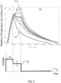
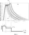
- FIGs. 8-9 show a number of temperature measurements at the surface of the thermoelectric.
- the voltage applied during the second regime II of the thermal pulse is varied, by magnitude (shown in FIG. 8 ) and duration (shown in FIG. 9 ).
- This demonstrates an ability for the thermal pulse(s) generated at the surface of the skin to be controlled and varied as desired.
- the temperature profile of a thermal pulse may be appropriately tailored to suit the thermal needs of the user.
- any suitable voltage profile may be applied to the thermoelectric material(s), according to any appropriate pattern.
- FIG. 8 shows a group of waveforms where the duration in which the optional second voltage V 2 was applied was kept constant, and the magnitude of the second applied voltage V 2 was varied.
- waveform 200 corresponds to the instance where no second voltage V 2 was applied (i.e., second voltage V 2 applied was zero) and waveform 210 corresponds to the case where the second voltage V 2 is greatest in magnitude amongst the group.
- the second voltage V 2 when the second voltage V 2 is effectively zero, the temperature relaxes in accordance with an exponential decay, as if a single square voltage V 1 was applied.
- the temperature at the surface may still increase, albeit not as sharply as in the case where the initial voltage V 1 is applied.
- the second voltage V 2 is no longer applied, the temperature profile exhibits relaxation decay behavior.
- the magnitude of the optional second voltage V 2 was kept constant and the duration of the second applied voltage V 2 was varied.
- the length of time between the second applied voltage V 2 and the third applied voltage V 3 was varied between 0 seconds and about 10 seconds.
- the waveform 300 corresponds to the instance where no second voltage V 2 was applied (applied for 0 seconds) and waveform 310 corresponds to the case where the second voltage V 2 is applied for the longest period of time (applied for 10 seconds) amongst the group.
- the second voltage V 2 may continue to increase or hover around a particular temperature range. And, as application of the second voltage V 2 ceases, the temperature at the surface decays back toward the initial temperature.
- the controller includes a current source, for generating a suitable electrical signal.
- the current source may apply a current to the thermoelectric material(s), for generating a thermal pulse at the surface of the skin of a user.
- the magnitude of a current applied to the thermoelectric material(s) at any given point may fall within a suitable range.
- the magnitude of a current applied to the thermoelectric material(s) may be between about 0.1 A and about 4.0 A, between about 0.1 A and about 3.5 A, between about 0.1 A and about 3.0 A, between about 0.2 A and about 2.5 A, between about 0.5 A and about 2.0 A, between about 1.0 A and about 2.0 A, between about 0.1 A and about 1.5 A, between about 0.1 A and about 1.0 A, between about 0.5 A and about 1.0 A, between about 0.1 A and about 0.5 A, between about 1.0 A and about 1.5 A, or any other appropriate range.
- the electrical signal(s) may be applied to the thermoelectric material(s) in accordance with any suitable form or pattern.
- the electrical signal(s) may be applied to the thermoelectric material(s) as one or more square waves (i.e., a constant voltage/current applied for a period of time), which may result in a particular rate of temperature change, depending on how the electrical signal is applied.
- the electrical signal(s) may exhibit more complex behavior, for example, the electrical signal(s) may be applied as a linear ramp function, non-linear, exponential, polynomial function, piecewise function, etc.
- a first square wave voltage is applied to the thermoelectric material(s), resulting in a sharp linear temperature adjustment at the surface of the skin from the first temperature T 1 to the second temperature T 2 .
- a second square wave voltage is applied, the magnitude of which is less than the magnitude of the first square wave, resulting in a relatively constant, insubstantial change in the temperature T 2 , T 2 ' at the surface of the skin.
- no voltage is applied, resulting in a thermal adjustment to the third temperature T 3 , which may be different from the first initial temperature T 1 by a small amount/percentage.
- the sensation of warming or cooling may be enhanced by generating a series of asymmetric thermal pulses (e.g., thermal pulses which have a faster average rate of temperature change on initiation than the average rate of temperature change on return) at the surface of the skin of a user.
- steady-state operation of the device may also include generating a series of thermal pulses in succession. That is, during steady-state operation, the temperature profile of thermal pulses generated in succession may be substantially identical.
- non-steady state thermal pulses may be suitable to enhance thermal sensation and/or comfort of the user and/or prevent desensitization to temperature changes.
- the duty cycle of the applied signal may be varied.
- the baseline average of the electrical signal may be gradually increased, as illustrated in FIG. 7 , or may gradually decrease, as desired.
- the average baseline signal may be adjusted as desired.
- non-steady state operation i.e., when operation of the device is first initiated, or when more/less power is applied to the thermoelectric at a given time
- non-steady state operation may allow for an increased amount of cooling or heating at the surface (e.g., more than the device may be designed to dissipate) for a temporary period of time.
- the controller may apply an electrical signal to the thermoelectric material(s) according to a suitable duty cycle.
- duty cycle as known in the art generally refers to the percentage of a time period in which an electrical signal is active.
- the electrical signal applied to the thermoelectric material(s) by the controller may exhibit a duty cycle of between about 10% and about 50%, greater than or equal to about 10%, greater than or equal to about 20%, greater than or equal to about 30%, greater than or equal to about 40%, or greater than or equal to about 50%.
- the duty cycle applied by the controller may be less than about 50%, less than about 40%, less than about 30%, less than about 20%, or less than about 10%. Combinations of the above referenced ranges are also possible (e.g., between about 10% and about 50%).
- the particular ranges of electrical signal are non-limiting and may suitably vary depending, in part, on the overall configuration of the device, particular materials selected (e.g., thermoelectric materials, number of thermoelectric materials), intrinsic resistances of various components within the device, or other aspects that may contribute to the functionality of the device.
- the thermal adjustment portion of the device may include one or more thermoelectric materials.
- the thermoelectric materials may, in some embodiments, be preferable for generating rapid, reversible thermal transients (i.e. thermal pulses).
- suitable thermoelectric materials may include columns of p-type and n-type doped semiconductor materials, bismuth chalcogenides (e.g., Bi 2 Te 3 , Bi 2 Se 3 ), lead selenide, Si-Ge alloys, skutterudites (e.g., including the formula LM 4 X 12 , wherein L is a rare earth metal, M is a transition metal, and X is a metalloid), or any other suitable thermoelectric materials.
- the thermoelectric material(s) may have any suitable thickness.
- the thickness may be selected such that the thermoelectric material(s) may be comfortably held against the wrist, arm, leg, ankle, neck, or any other suitable part of the body.
- the thickness of each of the thermoelectric materials may be between about 1 millimeter and about 5 millimeters (e.g., between about 1 millimeter and about 3 millimeters). Other thicknesses are also possible.
- each of the thermoelectric materials, or modules that include the thermoelectric material(s) may have a largest average cross-sectional dimension of between about 10 mm and about 4 cm (e.g., between about 30 mm and about 500 mm). Other average cross-sectional dimensions are also possible. Those skilled in the art would be capable of selecting an appropriate size for the thermoelectric material based upon the configuration of the device.
- Thermoelectric materials, or modules thereof, may be provided in any suitable configuration.
- a module may include thermoelectric materials sandwiched between ceramic plates, in some cases, for protection and support, as well as to provide thermal conductivity to the surface of the skin.
- the device may include a thermally insulative material 122 that is positioned so as to cover the thermoelectric material(s) 110.
- the thermoelectric material(s) may be located between the thermally insulative material and the surface of the skin.
- the thermally insulative material may be effective to retain the level of heat (or cooling) generated by the thermoelectric material(s), adjacent the surface.
- the thermally insulative material may increase the overall magnitude of temperature change for a given electrical signal, as compared to the use of thermally conductive materials.
- incorporation of a thermally insulative material may give rise to stronger or otherwise enhanced thermal pulsing, for example, increasing the overall sensation of temperature change for a user, and/or a reduction in power consumption by the device.
- FIG. 10 depicts an example where a series of thermal heating pulses are observed, with the same application of electrical signal, for a thermoelectric material covered by a thermally insulative material (e.g., neoprene), as compared to a thermoelectric material covered by a thermally conductive material (e.g., aluminum, other metal(s)).
- a thermally insulative material e.g., neoprene
- a thermally conductive material e.g., aluminum, other metal(s)
- the device may incorporate a thermally conductive material, for example, for thermal dissipation of the generated heating or cooling.
- a thermally conductive material for example, for thermal dissipation of the generated heating or cooling.
- it may be desirable to switch rapidly between heating and cooling modes. Accordingly, the ability to dissipate heat may allow for residual heating or cooling to be reduced.
- any suitable dissipation unit may be employed, for example, a heat sink, a fan, a phase change material, a heat exchanger, or combinations thereof.
- the thermal dissipation unit has a size and/or weight such that it can be mounted comfortably on the device and, in turn, for example, on a wrist, as illustrated in FIGs. 1A-1C .
- the device includes a suitable power source.
- the power source may include any appropriate materials, such as one or more batteries, photovoltaic cells, etc.
- suitable batteries include Li-polymer (e.g., with between about 100 and about 1000 mAh of battery life), Li-ion, nickel cadmium, nickel metal hydride, or the like.
- the battery may output a constant voltage and the controller may be configured to apply an appropriate degree of pulse-width modulation to generate time-varying voltage profiles.
- the device may be further configured to use relatively low amounts of power, in contrast with HVAC systems or other localized electronic thermal sources such as heaters, fans, or the like.
- the device may include one or more sensors arranged to collect information at the region of the thermoelectric material(s) adjacent the surface. Any suitable sensor(s) may be employed, for example, temperature sensors (e.g., thermistors, thermocouples), humidity and/or moisture sensors, barometers, etc., in any appropriate configuration.
- the device includes one or more temperature sensors for monitoring the temperature at the surface of the thermoelectric material(s) and/or skin.
- the senor may send a signal to the controller to adjust the applied electrical signal (e.g., apply a negative (or lower) voltage to reduce the temperature, apply a positive (or higher) voltage to increase the temperature) to result in a preferred temperature profile.
- the applied electrical signal e.g., apply a negative (or lower) voltage to reduce the temperature, apply a positive (or higher) voltage to increase the temperature
- the temperature sensor may be incorporated with the controller, for monitoring the temperature of the controller.
- one or more temperature sensors may be placed directly adjacent one or more surfaces of the thermoelectric material(s).
- the temperature sensor(s) may be arranged for sensing the temperature of ambient air.
- the temperature sensor(s) may measure the temperature difference across different components of the device (e.g., between the surface of the skin and the thermoelectric material(s), between the thermoelectric material(s) and ambient air).
- the temperature sensor(s) in some embodiments, may be configured with the controller to operate in accordance with a feedback loop, for example, to prevent excessive heating or cooling of the device and/or to maintain the temperature at the surface within a preferred range.
- the device may include additional control features, as desired, for example, wireless capabilities for enabling suitable communication with other devices/systems (e.g., for controlling aspects of the device, controlling/monitoring the temperature at the surface of the skin, etc.).
- Wireless devices are generally known in the art and may include, in some cases, wifi and/or Bluetooth systems.
- the device may be used for therapeutic applications.
- the device may be used to alleviate hot flashes (e.g., during pregnancy, during menopause), or provide thermal comfort in humid or arid environments Accordingly, the foregoing description and drawings are by way of example only.
Landscapes
- Health & Medical Sciences (AREA)
- Engineering & Computer Science (AREA)
- General Health & Medical Sciences (AREA)
- Physics & Mathematics (AREA)
- General Physics & Mathematics (AREA)
- Animal Behavior & Ethology (AREA)
- Vascular Medicine (AREA)
- Life Sciences & Earth Sciences (AREA)
- Heart & Thoracic Surgery (AREA)
- Biomedical Technology (AREA)
- Public Health (AREA)
- Veterinary Medicine (AREA)
- Environmental & Geological Engineering (AREA)
- Physical Education & Sports Medicine (AREA)
- Textile Engineering (AREA)
- Thermotherapy And Cooling Therapy Devices (AREA)
- Measuring And Recording Apparatus For Diagnosis (AREA)
- Control Of Temperature (AREA)
Claims (15)
- Dispositif (100) de manipulation d'une température d'une surface cutanée (102) d'un corps, comprenant :au moins un matériau thermoélectrique (110, 110A à 110D) fabriqué et agencé pour être disposé de manière adjacente à la surface (102) ; etun dispositif de commande (140) en communication électrique avec l'au moins un matériau thermoélectrique (110, 110A à 110D),le dispositif de commande (140) étant configuré pour amener l'au moins un matériau thermoélectrique (110, 110A à 110D) à générer une impulsion thermique d'une durée inférieure à 10 secondes au niveau d'une région de l'au moins un matériau thermoélectrique (110, 110A à 110D) adjacent à la surface (102), l'impulsion thermique incluant un premier réglage de température au niveau de la région de l'au moins un matériau thermoélectrique (110, 110A à 110D) adjacent à la surface (102) d'une première température (T1) à une deuxième température (T2) à une première vitesse moyenne d'entre environ 0,1 °C/sec et environ 10,0 °C/sec, et un second réglage de température au niveau de la région de l'au moins un matériau thermoélectrique (110, 110A à 110D) adjacent à la surface (102) de la deuxième température (T2) à une troisième température (T3) à une seconde vitesse moyenne d'entre environ 0,1 °C/sec et environ 10,0 °C/sec,dans lequel le premier et le second réglage de température sont entre 1 °C et 6 °C etdans lequel le dispositif est incorporé dans un vêtement ou dans lequel le dispositif comporte une bande portable reliée à l'au moins un matériau thermoélectrique.
- Dispositif (100) selon la revendication 1, dans lequel le dispositif de commande (140) est configuré pour amener l'au moins un matériau thermoélectrique (110, 110A à 110D) à générer l'impulsion thermique :i) sur une durée inférieure à 30 secondes ; et/ouii) de telle sorte qu'une amplitude de la première vitesse moyenne soit supérieure à une amplitude de la seconde vitesse moyenne.
- Dispositif (100) selon l'une quelconque des revendications précédentes, dans lequel le premier réglage de température se produit sur une durée plus courte que le second réglage de température.
- Dispositif (100) selon l'une quelconque des revendications précédentes, dans lequel le dispositif de commande (140) est configuré pour
amener l'au moins un matériau thermoélectrique (110, 110A à 110D) à générer l'impulsion thermique de sorte que :i) la différence d'amplitude entre la première température et la deuxième température soit inférieure à 10 °C ; et/ouii) la différence d'amplitude entre la première température et la troisième température (T3) soit inférieure à 10 % de la différence d'amplitude entre la première température et la deuxième température. - Dispositif (100) selon l'une quelconque des revendications précédentes, dans lequel le dispositif de commande (140) est configuré pour
amener l'au moins un matériau thermoélectrique (110, 110A à 110D) à générer l'impulsion thermique de telle sorte qu'au moins une partie du premier réglage de température présente :i) un comportement sensiblement linéaire dans le temps ; ouii) un comportement de décroissance sensiblement exponentielle dans le temps. - Dispositif (100) selon l'une quelconque des revendications précédentes, dans lequel le dispositif de commande (140) est configuré pouramener l'au moins un matériau thermoélectrique (110, 110A à 110D) à générer l'impulsion thermiquede telle sorte que le premier réglage de température inclut :i) une augmentation de température au niveau de la région de l'au moins un matériau thermoélectrique (110, 110A à 110D) adjacent à la surface (102) de la première température (T1) à la deuxième température (T2), et le second réglage de température inclut une diminution de température au niveau de la région de l'au moins un matériau thermoélectrique (110, 110A à 110D) adjacent à la surface (102) de la deuxième température (T2) à la troisième température (T3), dans lequel la deuxième température (T2) est supérieure à la première température et la troisième température (T3) est inférieure à la deuxième température (T2) ; ouii) une diminution de température au niveau de la région de l'au moins un matériau thermoélectrique (110A à 110D) adjacent à la surface (102) de la première température (T1) à la deuxième température, et le second réglage de température inclut une augmentation de température au niveau de la région de l'au moins un matériau thermoélectrique (110, 110A à 110D) adjacent à la surface (102) de la deuxième température (T2) à la troisième température (T3), dans lequel la deuxième température (T2) est inférieure à la première température et la troisième température (T3) est supérieure à la deuxième température (T2).
- Dispositif (100) selon l'une quelconque des revendications précédentes, dans lequel le dispositif de commande (140) est configuré pour
appliquer le signal électrique à l'au moins un matériau thermoélectrique (110, 110A à 110D) à un cycle de service d'entre environ 1 % et environ 50 %. - Dispositif (100) selon l'une quelconque des revendications précédentes, dans lequel la surface (102) inclut de la peau vivante (102).
- Dispositif (100) selon l'une quelconque des revendications précédentes, dans lequel l'au moins un matériau thermoélectrique inclut une pluralité de matériaux thermoélectriques (110, 110A à 110D) situés de manière adjacente les uns aux autres le long de la surface (102).
- Dispositif (100) selon l'une quelconque des revendications précédentes, comprenant en outre un matériau thermiquement isolant (122) situé de manière adjacente à l'au moins un matériau thermoélectrique (110, 110A à 110D), le matériau thermiquement isolant (122) étant configuré pour retenir de la chaleur au niveau de la région de l'au moins un matériau thermoélectrique adjacent à la surface (102).
- Dispositif (100) selon l'une quelconque des revendications précédentes, dans lequel le dispositif de commande (140) est configuré pour amener l'au moins un matériau thermoélectrique (110, 110A à 110D) à générer une pluralité d'impulsions thermiques successives au niveau de la région de l'au moins un matériau thermoélectrique (110, 110A à 110D) adjacent à la surface (102).
- Procédé de manipulation d'une température d'une surface cutanée (102) d'un corps pour améliorer une sensation thermique d'un utilisateur et fournir à l'utilisateur une expérience thermique améliorée grâce à une impulsion thermique, comprenant :le fait de positionner une région de l'au moins un matériau thermoélectrique (110, 110A à 110D) adjacent à la surface (102) avec un vêtement ou une bande portable accouplée à l'au moins un matériau thermoélectrique ; etle fait de générer une impulsion thermique d'une durée inférieure à 10 secondes au niveau d'une région de l'au moins un matériau thermoélectrique (110, 110A à 110D) adjacent à la surface (102), dans lequel la génération de l'impulsion thermique inclut :le fait de régler la température au niveau de la région de l'au moins un matériau thermoélectrique (110, 110A à 110D) adjacent à la surface (102) d'une première température (T1) à une deuxième température (T2) à une première vitesse moyenne d'entre environ 0,1 °C/sec et environ 10,0 °C/sec, etle fait de régler la température au niveau de la région de l'au moins un matériau thermoélectrique (110, 110A à 110D) adjacent à la surface (102) de la deuxième température (T2) à une troisième température (T3) à une seconde vitesse moyenne d'entre environ 0,1 °C/sec et environ 10,0 °C/sec,dans lequel le premier et le second réglage de température est entre 1 °C et 6 °C.
- Procédé selon la revendication 12, dans lequel la génération de l'impulsion thermique se produit sur une durée inférieure à 30 secondes.
- Procédé selon l'une quelconque des revendications 12 et 13, dans lequel l'amplitude de la première vitesse moyenne est supérieure à l'amplitude de la seconde vitesse moyenne d'au moins 10 % de la première vitesse moyenne.
- Procédé selon l'une quelconque des revendications 12 à 14, dans lequel le réglage de température de la première température (T1) à la deuxième température (T2) inclut :i) une augmentation de température au niveau de la région de l'au moins un matériau thermoélectrique (110, 110A à 110D) adjacent à la surface (102) de la première température (T1) à la deuxième température (T2) et
le réglage de température de la deuxième température (T2) à la troisième température (T3) inclut une diminution de température au niveau de la région de l'au moins un matériau thermoélectrique (110, 110A à 110D) adjacent à la surface (102) de la deuxième température (T2) à la troisième température (T3), dans lequel la deuxième température (T2) est supérieure à la première température (T1) et la troisième température (T3) est inférieure à la deuxième température (T2) ; ouii) une diminution de température au niveau de la région de l'au moins un matériau thermoélectrique (110, 110A à 110D) adjacent à la surface (102) de la première température (T1) à la deuxième température (T2), et un réglage de température de la deuxième température (T2) à la troisième température (T3) inclut une augmentation de température au niveau de la région de l'au moins un matériau thermoélectrique (110, 110A à 110D) adjacent à la surface (102) de la deuxième température (T2) à la troisième température, dans lequel la deuxième température est inférieure à la première température (T1) et la troisième température (T3) est supérieure à la deuxième température (T2).
Priority Applications (1)
| Application Number | Priority Date | Filing Date | Title |
|---|---|---|---|
| EP25152534.1A EP4566575A3 (fr) | 2013-10-11 | 2014-10-10 | Procédés et appareils de manipulation de température |
Applications Claiming Priority (2)
| Application Number | Priority Date | Filing Date | Title |
|---|---|---|---|
| US201361889996P | 2013-10-11 | 2013-10-11 | |
| PCT/US2014/060100 WO2015054615A1 (fr) | 2013-10-11 | 2014-10-10 | Procédés et appareils de manipulation de température |
Related Child Applications (1)
| Application Number | Title | Priority Date | Filing Date |
|---|---|---|---|
| EP25152534.1A Division EP4566575A3 (fr) | 2013-10-11 | 2014-10-10 | Procédés et appareils de manipulation de température |
Publications (4)
| Publication Number | Publication Date |
|---|---|
| EP3054800A1 EP3054800A1 (fr) | 2016-08-17 |
| EP3054800A4 EP3054800A4 (fr) | 2017-07-19 |
| EP3054800C0 EP3054800C0 (fr) | 2025-01-29 |
| EP3054800B1 true EP3054800B1 (fr) | 2025-01-29 |
Family
ID=52813676
Family Applications (2)
| Application Number | Title | Priority Date | Filing Date |
|---|---|---|---|
| EP25152534.1A Pending EP4566575A3 (fr) | 2013-10-11 | 2014-10-10 | Procédés et appareils de manipulation de température |
| EP14851667.7A Active EP3054800B1 (fr) | 2013-10-11 | 2014-10-10 | Procédés et appareils de manipulation de température |
Family Applications Before (1)
| Application Number | Title | Priority Date | Filing Date |
|---|---|---|---|
| EP25152534.1A Pending EP4566575A3 (fr) | 2013-10-11 | 2014-10-10 | Procédés et appareils de manipulation de température |
Country Status (4)
| Country | Link |
|---|---|
| US (1) | US12390361B2 (fr) |
| EP (2) | EP4566575A3 (fr) |
| JP (2) | JP2016538972A (fr) |
| WO (1) | WO2015054615A1 (fr) |
Families Citing this family (11)
| Publication number | Priority date | Publication date | Assignee | Title |
|---|---|---|---|---|
| AU2012271323C1 (en) * | 2011-06-17 | 2017-05-25 | My Core Control, LLC | Electronic personal thermal control apparatus and system |
| WO2016209834A1 (fr) | 2015-06-22 | 2016-12-29 | Quantum Dynamics L.L.C. | Dispositif permettant de fournir une régulation de la température corporelle et/ou une lumière thérapeutique dirigée vers le système vasculaire |
| US10842205B2 (en) * | 2016-10-20 | 2020-11-24 | Nike, Inc. | Apparel thermo-regulatory system |
| JP2020057031A (ja) * | 2017-02-06 | 2020-04-09 | アルプスアルパイン株式会社 | 触覚呈示装置 |
| WO2018194471A2 (fr) * | 2017-02-16 | 2018-10-25 | Universidad Tecnológica De Panamá | Accessoire vestimentaire réfrigéré pour la tête |
| EP4325518A3 (fr) | 2017-10-12 | 2024-06-26 | EMBR Labs IP LLC | Actionneurs haptiques et leurs procédés d'utilisation |
| WO2019152172A1 (fr) | 2018-01-31 | 2019-08-08 | Embr Labs Inc. | Procédés et systèmes de dissipation de charges thermiques dans des dispositifs techno vestimentaires |
| US12296129B2 (en) | 2018-03-07 | 2025-05-13 | Soovu Labs, Inc. | Systems and methods for improved pain relief from stimulation of thermal fibers |
| JP7631885B2 (ja) * | 2021-02-24 | 2025-02-19 | オムロン株式会社 | ヘッドフォン |
| CN114217649A (zh) * | 2021-11-22 | 2022-03-22 | 中国安全生产科学研究院 | 一种基于热电器件的消防手套降温系统及方法 |
| GB2640675A (en) * | 2024-04-30 | 2025-11-05 | Kum Florence | Thermoelectric cooling device for enhanced human exercise performance |
Family Cites Families (109)
| Publication number | Priority date | Publication date | Assignee | Title |
|---|---|---|---|---|
| US1941173A (en) | 1931-11-21 | 1933-12-26 | Purdue Research Foundation | Process and device for cooling the animal body |
| US2715315A (en) | 1954-06-11 | 1955-08-16 | Gino A Giardini | Localized applicator for cooling body temperatures |
| US2798494A (en) | 1955-08-11 | 1957-07-09 | Sukacev Lev | Devices for transferring thermoelectric power effects to the skin of a human |
| GB1430627A (en) | 1972-03-29 | 1976-03-31 | Int Promotion Eng Sa | Apparatus for producing cold for localized application to a living body |
| US4470263A (en) | 1980-10-14 | 1984-09-11 | Kurt Lehovec | Peltier-cooled garment |
| DE3128107C2 (de) | 1981-07-16 | 1983-07-21 | GMS, Gesellschaft für medizinische Sondentechnik mbH, 2300 Kiel | Impulsbeheizte thermoelektrische Strömungsmeßeinrichtung für lebendes Gewebe |
| US4640284A (en) | 1985-07-22 | 1987-02-03 | Ruderian Max J | Hot and cold direct contact applicator |
| US4585002A (en) | 1985-04-22 | 1986-04-29 | Igor Kissin | Method and apparatus for treatment of pain by frequently alternating temperature stimulation |
| JPS6282963A (ja) * | 1985-10-07 | 1987-04-16 | オムロン株式会社 | 温冷治療装置 |
| USD298458S (en) | 1986-04-03 | 1988-11-08 | Ely Margolin | Thermoelectric device for heating and cooling the skin |
| JPS63229047A (ja) * | 1987-03-17 | 1988-09-22 | 大竹 直 | 温度誘発痛による過剰刺激鎮痛装置 |
| US4860748A (en) * | 1988-02-23 | 1989-08-29 | Thermapeutics, Inc. | Thermal pattern generator for pain relief |
| US4930317A (en) | 1988-05-20 | 1990-06-05 | Temperature Research Corporation | Apparatus for localized heat and cold therapy |
| DE3905570A1 (de) | 1989-02-06 | 1990-08-23 | Wilfried Geiselhart | Elektronische heiz- und kuehlmanschette fuer heilzwecke |
| US5092129A (en) | 1989-03-20 | 1992-03-03 | United Technologies Corporation | Space suit cooling apparatus |
| US5097829A (en) | 1990-03-19 | 1992-03-24 | Tony Quisenberry | Temperature controlled cooling system |
| US5097828A (en) | 1990-09-25 | 1992-03-24 | Richard Deutsch | Thermoelectric therapy device |
| US5269369A (en) | 1991-11-18 | 1993-12-14 | Wright State University | Temperature regulation system for the human body using heat pipes |
| US5374123A (en) | 1992-05-20 | 1994-12-20 | Goldstar Co., Ltd. | Thermal comfort sensing device |
| RU2047298C1 (ru) * | 1993-05-27 | 1995-11-10 | Специализированное конструкторско-технологическое бюро "Норд" | Устройство для криомассажа |
| US5447530A (en) | 1994-03-28 | 1995-09-05 | Guibert; Raul | Periodic pulsed heat technique for inducing analgesic effects |
| US5628769A (en) | 1994-09-30 | 1997-05-13 | Saringer Research, Inc. | Method and devices for producing somatosensory stimulation using temperature |
| FR2732113B1 (fr) * | 1995-03-23 | 1997-04-30 | Imra Europe Sa | Procede pour detecter de facon precoce un risque de condensation d'eau sur une surface se trouvant au contact d'un volume d'air humide |
| EP0854696B1 (fr) | 1995-10-11 | 2002-01-30 | Kool Limited | Commande de chaleur personnelle |
| US5800481A (en) | 1995-12-28 | 1998-09-01 | Loos; Hendricus G. | Thermal excitation of sensory resonances |
| US6091994A (en) | 1995-12-28 | 2000-07-18 | Loos; Hendricus G. | Pulsative manipulation of nervous systems |
| US5956963A (en) | 1996-01-18 | 1999-09-28 | Lerner; Irene K. | Wrist cooler for relief of hot flashes and similar symptoms |
| US5800490A (en) | 1996-11-07 | 1998-09-01 | Patz; Herbert Samuel | Lightweight portable cooling or heating device with multiple applications |
| JPH1142282A (ja) * | 1997-07-28 | 1999-02-16 | Matsushita Electric Works Ltd | 額温制御装置とこれを用いた覚醒維持装置及び入眠促進装置 |
| CA2245606A1 (fr) | 1997-08-25 | 1999-02-25 | Robert Johnston | Dispositif de refroidissement topique |
| US6407965B1 (en) | 1997-10-14 | 2002-06-18 | Seiko Instruments Inc. | Timepiece having thermoelectric generator unit |
| WO1999035626A1 (fr) | 1998-01-09 | 1999-07-15 | Gert Rippbauer | Procede et dispositif pour empecher des personnes de s'endormir |
| JP3051919B2 (ja) | 1998-11-13 | 2000-06-12 | セイコーインスツルメンツ株式会社 | 熱発電式電子機器 |
| JP3079375B2 (ja) | 1998-11-13 | 2000-08-21 | セイコーインスツルメンツ株式会社 | 腕携帯機器 |
| US6125636A (en) | 1999-01-14 | 2000-10-03 | Sharper Image Corporation | Thermo-voltaic personal cooling/heating device |
| US7744640B1 (en) | 1999-08-11 | 2010-06-29 | Medical Products, Inc. | Thermal treatment garment and method of thermally treating body portions |
| KR100346196B1 (ko) | 1999-11-11 | 2002-07-26 | 삼성전자 주식회사 | 피부접촉형 단말기에서 열형태 경보신호를 제공하는 장치및그 제어방법 |
| JP2001190586A (ja) | 2000-01-11 | 2001-07-17 | Ohiro Seisakusho:Kk | 美顔器 |
| US6840955B2 (en) | 2000-01-27 | 2005-01-11 | Robert J. Ein | Therapeutic apparatus |
| US6311497B1 (en) | 2000-03-22 | 2001-11-06 | Young-Chun Chung | Device for cold and warm formentations |
| JP4663208B2 (ja) | 2000-05-31 | 2011-04-06 | シチズンホールディングス株式会社 | 熱発電時計 |
| DE10141083B4 (de) | 2001-08-22 | 2006-02-16 | Siemens Ag | Verfahren und Anordnung zur Temperaturregelung eines Peltier-Elements |
| US6438964B1 (en) | 2001-09-10 | 2002-08-27 | Percy Giblin | Thermoelectric heat pump appliance with carbon foam heat sink |
| US6739138B2 (en) | 2001-11-26 | 2004-05-25 | Innovations Inc. | Thermoelectric modules and a heating and cooling apparatus incorporating same |
| US8840608B2 (en) | 2002-03-15 | 2014-09-23 | The General Hospital Corporation | Methods and devices for selective disruption of fatty tissue by controlled cooling |
| WO2004014169A2 (fr) | 2002-08-07 | 2004-02-19 | Phoenix Consultants, Ltd | Vêtement à régulation de température |
| US6735083B2 (en) | 2002-08-07 | 2004-05-11 | Inventec Corporation | Porous CPU cooler |
| US20040059400A1 (en) | 2002-09-25 | 2004-03-25 | Ray-Ming Lin | Electric fever relief device |
| JP2004173750A (ja) * | 2002-11-25 | 2004-06-24 | Omron Healthcare Co Ltd | 電気温熱式治療器 |
| US6915641B2 (en) | 2003-01-14 | 2005-07-12 | Mark R. Harvie | Personal cooling and heating system |
| US7037326B2 (en) | 2003-03-14 | 2006-05-02 | Hee-Young Lee | Skin cooling device using thermoelectric element |
| DE10314138A1 (de) | 2003-03-25 | 2004-10-07 | Krüger & Gothe GmbH | Wärme/Kältevorrichtung |
| EP1631222B1 (fr) | 2003-05-22 | 2007-01-03 | Medoc Ltd. | Sonde et procede de stimulation thermique |
| KR20040100763A (ko) | 2003-05-24 | 2004-12-02 | 안문휘 | 혈압 강하기 |
| CA2432860A1 (fr) | 2003-06-16 | 2004-12-16 | Dupont Canada Inc. | Systeme electronique personnel reparti de gestion de la chaleur |
| KR100519343B1 (ko) | 2003-07-02 | 2005-10-07 | 엘지전자 주식회사 | 기능성 의복 |
| US7124593B2 (en) | 2003-09-02 | 2006-10-24 | Steve Feher | Temperature conditioning apparatus for the trunk of a human body |
| PT103030A (pt) | 2003-10-17 | 2005-04-29 | Bruno Manuel Nunes Ra Carvalho | Vestuario autonomo, alimentado por paineis solares e com controlo activo da temperatura |
| US7347060B2 (en) | 2003-11-14 | 2008-03-25 | Aqueduct Medical, Inc. | Systems for regulating the temperature of a heating or cooling device using non-electric controllers and non-electric controllers therefor |
| US6823678B1 (en) | 2003-12-22 | 2004-11-30 | Ferrotec (Usa) Corporation | Air conditioner system for flexible material-based devices |
| US20050193742A1 (en) | 2004-02-10 | 2005-09-08 | Its Kool, Llc | Personal heat control devicee and method |
| US8062797B2 (en) | 2004-05-07 | 2011-11-22 | Ardica Technologies, Inc. | Articles of clothing and personal gear with on-demand power supply for electrical devices |
| US20060141308A1 (en) | 2004-12-23 | 2006-06-29 | Becerra Juan J | Apparatus and method for variable conductance temperature control |
| GB2422109B (en) | 2005-01-13 | 2007-02-21 | Richard Mills | Apparatus for providing a heating and cooling effect |
| WO2006086513A2 (fr) | 2005-02-08 | 2006-08-17 | Carewave, Inc. | Appareil et procede d'utilisation d'un dispositif thermique portatif pour reduire l'adaptation de recepteurs nerveux |
| EP1737052A1 (fr) * | 2005-06-20 | 2006-12-27 | Well &David Corporation | Dispositif de réglage de la chaleur |
| US7331183B2 (en) | 2005-10-03 | 2008-02-19 | The United States Of America As Represented By The Secretary Of The Navy | Personal portable environmental control system |
| CA2642886A1 (fr) | 2006-02-16 | 2007-08-30 | Denise C. Polacek | Dispositif et procede de refroidissement |
| ES1062854Y (es) | 2006-05-12 | 2006-11-01 | Del Castillo Arturo Melian | Dispositivo personal para producir frio o calor |
| EP2056686B1 (fr) | 2006-07-26 | 2013-03-06 | Fathallah Nahhas | Appareil de refroidissement pour réduire le risque de stérilité mâle dans des environnements réchauffés |
| US8147533B2 (en) | 2006-10-04 | 2012-04-03 | Mmj Labs, Llc | Device and method for the reduction of pain associated with needle sticks |
| US7816628B2 (en) | 2006-11-22 | 2010-10-19 | Products Of Tomorrow, Inc. | Heated garment |
| US8257414B2 (en) | 2006-11-28 | 2012-09-04 | Stryker Corporation | Thermal pumps with features |
| JP2008142108A (ja) * | 2006-12-06 | 2008-06-26 | Yamaha Corp | マッサージ装置 |
| US8267983B2 (en) | 2007-01-11 | 2012-09-18 | Scion Neurostim, Llc. | Medical devices incorporating thermoelectric transducer and controller |
| US8267984B2 (en) * | 2007-08-03 | 2012-09-18 | Scion Neurostim, Llc. | Neurophysiological activation by vestibular or cranial nerve stimulation |
| ES2277577B2 (es) | 2007-02-06 | 2010-01-18 | Sunilei Tecnologia Solar, S.A. | "elemento con acondicionamiento termico". |
| US20080314429A1 (en) | 2007-02-09 | 2008-12-25 | Stichting Imec Nederland | Method for Thermal Matching of a Thermoelectric Generator with a Heat Source Having High Thermal Resistance and Thermoelectric Generator thus Obtained |
| WO2008103742A2 (fr) | 2007-02-23 | 2008-08-28 | Dhama Apparel Innovations Private Ltd | Appareil présentant des capacités de chauffage et de refroidissement |
| EP1976034A3 (fr) | 2007-03-29 | 2011-11-09 | Stichting IMEC Nederland | Procédé de fabrication d'une thermopile, thermopile ainsi obtenue et générateur thermoélectrique comportant de telles thermopiles |
| AU2008284042B2 (en) | 2007-08-03 | 2013-06-27 | Scion NeuroStim, Inc. | Vestibular stimulation apparatus and associated methods of use |
| CA2716407C (fr) | 2008-02-29 | 2018-04-03 | Sensory Medical, Inc. | Dispositifs et procedes de traitement du syndrome des jambes sans repos |
| US8397158B1 (en) | 2008-03-31 | 2013-03-12 | Sonoa Networks India (PVT) Ltd | System and method for partial parsing of XML documents and modification thereof |
| JP2009278575A (ja) | 2008-05-19 | 2009-11-26 | Sharp Corp | 温度通知装置を備えた機器 |
| US8087823B2 (en) | 2008-08-18 | 2012-01-03 | International Business Machines Corporation | Method for monitoring thermal control |
| CN101444447B (zh) | 2008-12-23 | 2013-06-19 | 陈齐武 | 冷热敷保健装置 |
| US20100185267A1 (en) | 2009-01-22 | 2010-07-22 | Dickie Robert G | Method and apparatus for controlling menopausal hot flashes |
| PT104357A (pt) | 2009-01-26 | 2010-07-26 | Inocam Solua Es De Manufactura | Sistema actuador para controlo activo e autënomo da temperatura no interior do calãado |
| US20100198322A1 (en) | 2009-02-05 | 2010-08-05 | Disney Enterprises, Inc. | Personal temperature regulator |
| US20100204764A1 (en) | 2009-02-11 | 2010-08-12 | Garetz Bruce A | Method for Treating Hot Flashes Associated with Menopause During Sleep |
| US8255004B2 (en) | 2009-02-18 | 2012-08-28 | Qualcomm Incorporated | Methods and systems for communicating using variable temperature control |
| US8676168B2 (en) | 2009-02-20 | 2014-03-18 | Blackberry Limited | Method and apparatus for managing message notifications |
| US20100262135A1 (en) | 2009-04-14 | 2010-10-14 | Primaeva Medical, Inc. | Controlled delivery of therapeutic energy to tissue |
| WO2011075573A1 (fr) | 2009-12-18 | 2011-06-23 | Scion Neurostim, Llc | Dispositifs et méthodes pour la stimulation des nerfs vestibulaires et/ou crâniens |
| US20110071603A1 (en) | 2009-09-24 | 2011-03-24 | Joshua John Edward Moore | Cyclic Heat Therapy Device |
| EP2912974A3 (fr) | 2010-05-28 | 2015-12-09 | Marlow Industries, Inc. | Système de literie thermoélectrique commandée par un système de confort personnel |
| WO2011156643A1 (fr) | 2010-06-11 | 2011-12-15 | Mandel William R | Appareil pour le refroidissement et le réchauffement thérapeutiques d'une partie du corps d'un humain ou d'un mammifère |
| JP5723131B2 (ja) * | 2010-10-01 | 2015-05-27 | 株式会社自立コム | 警報方法および装置 |
| US9861519B2 (en) | 2010-12-16 | 2018-01-09 | Scion Neurostim, Llc | Apparatus and methods for titrating caloric vestibular stimulation |
| AU2012271323C1 (en) * | 2011-06-17 | 2017-05-25 | My Core Control, LLC | Electronic personal thermal control apparatus and system |
| US20120018418A1 (en) | 2011-09-30 | 2012-01-26 | Shantha Todata R | Temperature controllable shoes |
| US20130087180A1 (en) | 2011-10-10 | 2013-04-11 | Perpetua Power Source Technologies, Inc. | Wearable thermoelectric generator system |
| US8850206B2 (en) | 2011-11-15 | 2014-09-30 | Apple Inc. | Client-server system with security for untrusted server |
| US8397518B1 (en) * | 2012-02-20 | 2013-03-19 | Dhama Innovations PVT. Ltd. | Apparel with integral heating and cooling device |
| US20130333394A1 (en) | 2012-06-18 | 2013-12-19 | Felix Chow | Method and apparutus for performance enhancing body cooling with thermoelectric |
| US10182937B2 (en) | 2013-10-11 | 2019-01-22 | Embr Labs Inc. | Methods and apparatuses for manipulating temperature |
| JP2017511233A (ja) | 2014-03-03 | 2017-04-20 | フィジオキュー インコーポレイテッドPhysiocue, Inc. | 刺激システム、デバイス、使用方法について |
| EP3122295A1 (fr) | 2014-03-28 | 2017-02-01 | Lini, Mario | Dispositif et procédé de régulation de température corporelle |
| US20180042761A1 (en) | 2015-03-13 | 2018-02-15 | Embr Labs Inc. | Methods and apparatuses for manipulating temperature |
-
2014
- 2014-10-10 WO PCT/US2014/060100 patent/WO2015054615A1/fr not_active Ceased
- 2014-10-10 EP EP25152534.1A patent/EP4566575A3/fr active Pending
- 2014-10-10 JP JP2016547981A patent/JP2016538972A/ja active Pending
- 2014-10-10 EP EP14851667.7A patent/EP3054800B1/fr active Active
-
2019
- 2019-03-05 JP JP2019039628A patent/JP7333575B2/ja active Active
-
2023
- 2023-08-11 US US18/448,292 patent/US12390361B2/en active Active
Also Published As
| Publication number | Publication date |
|---|---|
| WO2015054615A1 (fr) | 2015-04-16 |
| US20240050272A1 (en) | 2024-02-15 |
| EP3054800A4 (fr) | 2017-07-19 |
| EP4566575A2 (fr) | 2025-06-11 |
| EP4566575A3 (fr) | 2025-09-24 |
| JP7333575B2 (ja) | 2023-08-25 |
| JP2022058461A (ja) | 2022-04-12 |
| US12390361B2 (en) | 2025-08-19 |
| JP2016538972A (ja) | 2016-12-15 |
| EP3054800C0 (fr) | 2025-01-29 |
| EP3054800A1 (fr) | 2016-08-17 |
| JP2019130319A (ja) | 2019-08-08 |
Similar Documents
| Publication | Publication Date | Title |
|---|---|---|
| US11759350B2 (en) | Methods and apparatuses for manipulating temperature | |
| US12390361B2 (en) | Methods and apparatuses for manipulating temperature | |
| US12213908B2 (en) | Methods and apparatuses for manipulating temperature | |
| US12169427B2 (en) | Methods and devices for manipulating temperature | |
| US20200345971A1 (en) | Wearable thermal devices and methods of using them | |
| US9849024B2 (en) | Apparatus for therapeutic cooling and warming of a body portion of a human or mammal | |
| EP3493776B1 (fr) | Dispositif de traitement thermique de la peau | |
| JP7319691B2 (ja) | ウェアラブルデバイスにおける熱負荷を放散する方法及びシステム | |
| US20180250159A1 (en) | Personal Microclimate Systems And Methods | |
| US10652993B2 (en) | Thermoelectric device cooling system | |
| CA2382928A1 (fr) | Vetement pour la thermoregulation | |
| WO2021087047A1 (fr) | Bandeau de refroidisseur thermoélectrique | |
| Lopez et al. | Development of a wrist-band type device for low-energy consumption and personalized thermal comfort | |
| JP7859823B2 (ja) | 温度を操作する方法及び装置 | |
| JP2004263325A (ja) | ペルチェ素子を用いた冷暖房服 | |
| KR101412630B1 (ko) | 열전소자를 이용한 냉온 찜질 기구 | |
| KR20040021829A (ko) | 열전소자를 이용한 냉온 겸용 찜질 기구 | |
| US20230168010A1 (en) | Temperature control device | |
| JP2019100676A (ja) | 温調装置および温調方法 | |
| KR20140066901A (ko) | 펠티어 소자를 구비한 냉온 찜질 장치 | |
| JP2025159913A (ja) | 電気刺激用装着具を温めるための加温庫 | |
| JP2020014698A (ja) | 人体加熱装置 |
Legal Events
| Date | Code | Title | Description |
|---|---|---|---|
| PUAI | Public reference made under article 153(3) epc to a published international application that has entered the european phase |
Free format text: ORIGINAL CODE: 0009012 |
|
| 17P | Request for examination filed |
Effective date: 20160426 |
|
| AK | Designated contracting states |
Kind code of ref document: A1 Designated state(s): AL AT BE BG CH CY CZ DE DK EE ES FI FR GB GR HR HU IE IS IT LI LT LU LV MC MK MT NL NO PL PT RO RS SE SI SK SM TR |
|
| AX | Request for extension of the european patent |
Extension state: BA ME |
|
| A4 | Supplementary search report drawn up and despatched |
Effective date: 20170616 |
|
| RIC1 | Information provided on ipc code assigned before grant |
Ipc: A41D 13/005 20060101AFI20170609BHEP Ipc: A61F 7/02 20060101ALI20170609BHEP Ipc: A61F 7/00 20060101ALI20170609BHEP Ipc: A44C 5/00 20060101ALI20170609BHEP |
|
| STAA | Information on the status of an ep patent application or granted ep patent |
Free format text: STATUS: EXAMINATION IS IN PROGRESS |
|
| RIC1 | Information provided on ipc code assigned before grant |
Ipc: A61F 7/00 20060101ALI20190709BHEP Ipc: A44C 5/00 20060101ALI20190709BHEP Ipc: A61F 7/02 20060101ALI20190709BHEP Ipc: A41D 13/005 20060101AFI20190709BHEP |
|
| 17Q | First examination report despatched |
Effective date: 20190719 |
|
| RAP1 | Party data changed (applicant data changed or rights of an application transferred) |
Owner name: EMBR LABS IP LLC |
|
| GRAP | Despatch of communication of intention to grant a patent |
Free format text: ORIGINAL CODE: EPIDOSNIGR1 |
|
| STAA | Information on the status of an ep patent application or granted ep patent |
Free format text: STATUS: GRANT OF PATENT IS INTENDED |
|
| INTG | Intention to grant announced |
Effective date: 20240821 |
|
| GRAS | Grant fee paid |
Free format text: ORIGINAL CODE: EPIDOSNIGR3 |
|
| GRAA | (expected) grant |
Free format text: ORIGINAL CODE: 0009210 |
|
| STAA | Information on the status of an ep patent application or granted ep patent |
Free format text: STATUS: THE PATENT HAS BEEN GRANTED |
|
| AK | Designated contracting states |
Kind code of ref document: B1 Designated state(s): AL AT BE BG CH CY CZ DE DK EE ES FI FR GB GR HR HU IE IS IT LI LT LU LV MC MK MT NL NO PL PT RO RS SE SI SK SM TR |
|
| REG | Reference to a national code |
Ref country code: GB Ref legal event code: FG4D |
|
| REG | Reference to a national code |
Ref country code: CH Ref legal event code: EP |
|
| REG | Reference to a national code |
Ref country code: DE Ref legal event code: R096 Ref document number: 602014091508 Country of ref document: DE |
|
| REG | Reference to a national code |
Ref country code: IE Ref legal event code: FG4D |
|
| U01 | Request for unitary effect filed |
Effective date: 20250210 |
|
| U07 | Unitary effect registered |
Designated state(s): AT BE BG DE DK EE FI FR IT LT LU LV MT NL PT RO SE SI Effective date: 20250214 |
|
| PG25 | Lapsed in a contracting state [announced via postgrant information from national office to epo] |
Ref country code: RS Free format text: LAPSE BECAUSE OF FAILURE TO SUBMIT A TRANSLATION OF THE DESCRIPTION OR TO PAY THE FEE WITHIN THE PRESCRIBED TIME-LIMIT Effective date: 20250429 |
|
| PG25 | Lapsed in a contracting state [announced via postgrant information from national office to epo] |
Ref country code: PL Free format text: LAPSE BECAUSE OF FAILURE TO SUBMIT A TRANSLATION OF THE DESCRIPTION OR TO PAY THE FEE WITHIN THE PRESCRIBED TIME-LIMIT Effective date: 20250129 |
|
| PG25 | Lapsed in a contracting state [announced via postgrant information from national office to epo] |
Ref country code: ES Free format text: LAPSE BECAUSE OF FAILURE TO SUBMIT A TRANSLATION OF THE DESCRIPTION OR TO PAY THE FEE WITHIN THE PRESCRIBED TIME-LIMIT Effective date: 20250129 |
|
| PG25 | Lapsed in a contracting state [announced via postgrant information from national office to epo] |
Ref country code: IS Free format text: LAPSE BECAUSE OF FAILURE TO SUBMIT A TRANSLATION OF THE DESCRIPTION OR TO PAY THE FEE WITHIN THE PRESCRIBED TIME-LIMIT Effective date: 20250529 Ref country code: NO Free format text: LAPSE BECAUSE OF FAILURE TO SUBMIT A TRANSLATION OF THE DESCRIPTION OR TO PAY THE FEE WITHIN THE PRESCRIBED TIME-LIMIT Effective date: 20250429 |
|
| PG25 | Lapsed in a contracting state [announced via postgrant information from national office to epo] |
Ref country code: HR Free format text: LAPSE BECAUSE OF FAILURE TO SUBMIT A TRANSLATION OF THE DESCRIPTION OR TO PAY THE FEE WITHIN THE PRESCRIBED TIME-LIMIT Effective date: 20250129 |
|
| PG25 | Lapsed in a contracting state [announced via postgrant information from national office to epo] |
Ref country code: GR Free format text: LAPSE BECAUSE OF FAILURE TO SUBMIT A TRANSLATION OF THE DESCRIPTION OR TO PAY THE FEE WITHIN THE PRESCRIBED TIME-LIMIT Effective date: 20250430 |
|
| PG25 | Lapsed in a contracting state [announced via postgrant information from national office to epo] |
Ref country code: SM Free format text: LAPSE BECAUSE OF FAILURE TO SUBMIT A TRANSLATION OF THE DESCRIPTION OR TO PAY THE FEE WITHIN THE PRESCRIBED TIME-LIMIT Effective date: 20250129 |
|
| PG25 | Lapsed in a contracting state [announced via postgrant information from national office to epo] |
Ref country code: CZ Free format text: LAPSE BECAUSE OF FAILURE TO SUBMIT A TRANSLATION OF THE DESCRIPTION OR TO PAY THE FEE WITHIN THE PRESCRIBED TIME-LIMIT Effective date: 20250129 |
|
| PG25 | Lapsed in a contracting state [announced via postgrant information from national office to epo] |
Ref country code: SK Free format text: LAPSE BECAUSE OF FAILURE TO SUBMIT A TRANSLATION OF THE DESCRIPTION OR TO PAY THE FEE WITHIN THE PRESCRIBED TIME-LIMIT Effective date: 20250129 |
|
| U20 | Renewal fee for the european patent with unitary effect paid |
Year of fee payment: 12 Effective date: 20251027 |
|
| PLBE | No opposition filed within time limit |
Free format text: ORIGINAL CODE: 0009261 |
|
| STAA | Information on the status of an ep patent application or granted ep patent |
Free format text: STATUS: NO OPPOSITION FILED WITHIN TIME LIMIT |
|
| 26N | No opposition filed |
Effective date: 20251030 |
|
| PGFP | Annual fee paid to national office [announced via postgrant information from national office to epo] |
Ref country code: GB Payment date: 20251027 Year of fee payment: 12 |