EP3058921A1 - Robot - Google Patents
Robot Download PDFInfo
- Publication number
- EP3058921A1 EP3058921A1 EP14854784.7A EP14854784A EP3058921A1 EP 3058921 A1 EP3058921 A1 EP 3058921A1 EP 14854784 A EP14854784 A EP 14854784A EP 3058921 A1 EP3058921 A1 EP 3058921A1
- Authority
- EP
- European Patent Office
- Prior art keywords
- tilting
- block
- rising
- falling
- main
- Prior art date
- Legal status (The legal status is an assumption and is not a legal conclusion. Google has not performed a legal analysis and makes no representation as to the accuracy of the status listed.)
- Granted
Links
Images


Classifications
-
- A—HUMAN NECESSITIES
- A61—MEDICAL OR VETERINARY SCIENCE; HYGIENE
- A61G—TRANSPORT, PERSONAL CONVEYANCES, OR ACCOMMODATION SPECIALLY ADAPTED FOR PATIENTS OR DISABLED PERSONS; OPERATING TABLES OR CHAIRS; CHAIRS FOR DENTISTRY; FUNERAL DEVICES
- A61G7/00—Beds specially adapted for nursing; Devices for lifting patients or disabled persons
- A61G7/10—Devices for lifting patients or disabled persons, e.g. special adaptations of hoists thereto
- A61G7/1013—Lifting of patients by
- A61G7/1019—Vertical extending columns or mechanisms
-
- A—HUMAN NECESSITIES
- A61—MEDICAL OR VETERINARY SCIENCE; HYGIENE
- A61G—TRANSPORT, PERSONAL CONVEYANCES, OR ACCOMMODATION SPECIALLY ADAPTED FOR PATIENTS OR DISABLED PERSONS; OPERATING TABLES OR CHAIRS; CHAIRS FOR DENTISTRY; FUNERAL DEVICES
- A61G7/00—Beds specially adapted for nursing; Devices for lifting patients or disabled persons
- A61G7/10—Devices for lifting patients or disabled persons, e.g. special adaptations of hoists thereto
- A61G7/1013—Lifting of patients by
- A61G7/1017—Pivoting arms, e.g. crane type mechanisms
-
- A—HUMAN NECESSITIES
- A61—MEDICAL OR VETERINARY SCIENCE; HYGIENE
- A61G—TRANSPORT, PERSONAL CONVEYANCES, OR ACCOMMODATION SPECIALLY ADAPTED FOR PATIENTS OR DISABLED PERSONS; OPERATING TABLES OR CHAIRS; CHAIRS FOR DENTISTRY; FUNERAL DEVICES
- A61G7/00—Beds specially adapted for nursing; Devices for lifting patients or disabled persons
- A61G7/10—Devices for lifting patients or disabled persons, e.g. special adaptations of hoists thereto
- A61G7/104—Devices carried or supported by
- A61G7/1046—Mobile bases, e.g. having wheels
-
- B—PERFORMING OPERATIONS; TRANSPORTING
- B25—HAND TOOLS; PORTABLE POWER-DRIVEN TOOLS; MANIPULATORS
- B25J—MANIPULATORS; CHAMBERS PROVIDED WITH MANIPULATION DEVICES
- B25J11/00—Manipulators not otherwise provided for
- B25J11/008—Manipulators for service tasks
- B25J11/009—Nursing, e.g. carrying sick persons, pushing wheelchairs, distributing drugs
-
- B—PERFORMING OPERATIONS; TRANSPORTING
- B25—HAND TOOLS; PORTABLE POWER-DRIVEN TOOLS; MANIPULATORS
- B25J—MANIPULATORS; CHAMBERS PROVIDED WITH MANIPULATION DEVICES
- B25J5/00—Manipulators mounted on wheels or on carriages
- B25J5/007—Manipulators mounted on wheels or on carriages mounted on wheels
-
- A—HUMAN NECESSITIES
- A61—MEDICAL OR VETERINARY SCIENCE; HYGIENE
- A61G—TRANSPORT, PERSONAL CONVEYANCES, OR ACCOMMODATION SPECIALLY ADAPTED FOR PATIENTS OR DISABLED PERSONS; OPERATING TABLES OR CHAIRS; CHAIRS FOR DENTISTRY; FUNERAL DEVICES
- A61G2203/00—General characteristics of devices
- A61G2203/10—General characteristics of devices characterised by specific control means, e.g. for adjustment or steering
Definitions
- the present invention is related to a robot. More specifically, the present invention is mainly related to a robot which is able to reduce burden of caregivers at a time of tranfering care receivers.
- care receivers life support for aged persons and physically handicapped persons
- caregivers such as care helpers
- the care receivers are transferred to wheelchairs from beds or to beds from wheelchairs to go to a restroom or to take a bath.
- the patent document No.1 discloses a carrier used in care.
- the carrier has a complex construction, so that the carrier cannot handle easily.
- Patent document No.1 Japanese Laid-open patent publication 2002-136549
- the purpose of the present invention is to provide a robot which is operated easily and is able to transfer a care receiver by one caregiver alone.
- the robot of the present invention comprises a movable block, a rising & falling block arranged on the movable block, a tilting block set to the rising & falling block, an operating block arranged on the tilting block and a pair of arms; wherein the tilting block has a main tilting part and an auxiliary tilting part arranged on the main tilting block; and the auxiliary tilting part has auxiliary tilting elements, holding the arms, rotatably set at the both ends of a main element of the main tilting part respectively.
- the main tilting part has a planetary gear mechanism including a sun gear and a pair of planetary gears arranged symmetrically to the sun gear; wherein the sun gear is supported by the top of the central rising & falling shaft of the rising & falling block and the main tilting element of the main tilting part in condition that the sun gear is unable to be rotated; one of the planetary gears is supported by the top of the one-side rising & falling shaft, which is set at one side of the central rising & falling shaft tiltably set on the base and at one side of the main tilting element of the main tilting part, in condition that the planetary gear is able to be rotated; and the other of the planetary gears is supported by the top of the other-side rising & falling shaft, which is set at the other side of the central rising & falling shaft tiltably set on the base and at the other side of the main tilting element of the main tilting part, in condition that the planetary gear is able to be rotated.
- the sun gear is supported by the top of the central
- the rising & falling block has a pair of rising & falling shafts; wherein the main tilting element is tilted by the rising & falling shafts.
- the auxiliary tilting element of the auxiliary tilting part is tilted by the rotating force of the planetary gear through a force transmitting mechanism arranged in the main tilting element.
- the auxiliary tilting element is rotated in the same direction as the tilting direction of the main tilting element.
- the arm is solid or hollow cylinder.
- the arm is supported by the auxiliary tilting element in condition that the arm is able to be moved forward and backward.
- the auxiliary tilting element has a locking mechanism which locks the arm at a prescribed position.
- the robot of the present invention it is preferable that the robot is covered with a decorative cover.
- the operating block has operating levers, an operating panel, and a control device; wherein the operating levers have actuating command means generating actuating command for the rising & falling block.
- the operating panel has a head position indicating means indicating position of a head, and a head position indicating display displaying position of the head in response to an indicating signal from the head position indicating means.
- control device has a signal input block, an input signal managing block, an arithmetic processing block, a driving command generation block and a signal output block; wherein the arithmetic processing block has a tilting processing section which has tilting command generation means and a limit processing means.
- the input signal managing block has a polarity discriminating means discriminating the polarity of the actuating command, a comparing means comparing the amplitude of the actuating command and a head position discriminating means discriminating head position based on a signal from the head position indicating means.
- the comparing means selects a smaller absolute value of the input signal.
- the limit processing means calculates the tilting angle based on the acceleration.
- the present invention is comprised as described above, so that one caregiver is able to move a care receiver from bed alone.
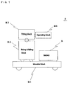
- Fig. 1 shows a functional block diagram of a robot R
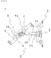
- Fig. 2 shows a schematic drawing of the robot R
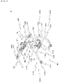
- Fig. 3 shows a tilting block in condition that the tilting block is tilted.
- the right-side and the left-side mean the right-side and the left-side of the robot in case of viewing the robot R from the rear thereof respectively.
- the robot R comprises a movable block M1, a rising & falling block M2 arranged on the movable block M1, a tilting block M3 set to the rising & falling block M2, and an operating block M4 arranged on the tilting block M3 as main components.
- the robot R has a base 100, movably constructed, composing the movable block M1, and a rising & falling shaft 3, arranged on the base 100 and composing the rising & falling block M2, tilting the tilting block M3 and rising and falling the tilting block M3.
- the base 100 is equipped with a battery B.
- the battery B supplies the operating block M4, the rising & falling block M2, and the tilting block M3 with electric power.
- the rising & falling shaft 3 includes a central rising & falling shaft 3C arranged at the center of the base 100, a right-side rising & falling shaft 3R near-by arranged at the right-side of the central rising & falling shaft 3C, and a left-side rising & falling shaft 3L near by arranged at the left-side of the central rising & falling shaft 3C.
- the right-side rising & falling shaft 3R and the left-side rising & falling shaft 3L are driving shaft
- the central rising & falling shaft 3C is driven shaft driven by the right-side rising & falling shaft 3R and the left-side rising & falling shaft 3L.
- the driving shafts are screw shafts so that the shafts are able to hold their position when the shafts are stopped, and the shafts have internal sensors (not shown) at the upper limit and the lower limit thereof so that the shafts are automatically stopped at the upper limit and the lower limit thereof respectively.
- Tilting of the tilting block M3 is carried out by tilting a tilting element 2 of the tilting block M3 with a tilting mechanism composed of a planetary gear unit 4, as a central component, comprising a sun gear arranged at the top of the central rising & falling shaft 3C, a right-side planetary gear arranged at the top of the right-side rising & falling shaft 3R and a left-side planetary gear arranged at the top of the left-side rising & falling shaft 3L
- Rising and falling of the tilting block M3 is carried out by rising and falling the tilting element 2 of the tilting block M3 with rising and falling the right-side rising & falling shaft 3R and the left-side rising & falling shaft 3L synchronously. Detail of the planetary gear unit 4 is described later.
- the movement range of the tilting block M3 by the rising & falling shaft 3 is restricted in the range of 750 mm to 1150 mm, and tilting angle of the head-side of the tilting block M3 is restricted in the range of +45 degrees to 0 degrees.
- the movement range and the tilting angle are not limited to the above-described range.
- the tilting angle is able to be freely selected not to exceed +90 degrees.
- the robot R includes the base 100 movably constructed, the rising & falling block M2 arranged on the base 100, and the tilting block M3 set to the rising & falling block M2.
- the tilting element 2 of the tilting block M3 is equipped with a pair of arm elements 20, 20 at the both ends thereof. Namely, the right-side end thereof is equipped with a right-side arm element 21, and the left-side end thereof is equipped with a left-side arm element 22.
- the base 100 includes a carrying block 110 arranged on the center of the base 100, and moving mechanisms 160 set at the both sides of the carrying block 110.
- the carrying block 110 includes a carrying element 120 arranged at the center of the carrying block 110, and a horizontal support element 130 supporting the carrying element 120 elongated right and left directions.
- the carrying block 110 more concretely, the carrying element 120 is equipped with the rising & falling block M2 and so on.
- the moving mechanism 160 includes a front moving mechanism 170, a middle moving mechanism 180 and a rear moving mechanism 190.
- the front moving mechanism 170 includes front wheels 171 and front wheel support elements 172.
- the front wheel support element 172 is set to the front end of a front wheel support element holding element 175 including a front horizontal part 173 and a rear upslope part 174. More concretely, the front wheel support element 172 is set to the front end of the front horizontal part 173.
- the middle moving mechanism 180 includes middle wheels 181 and middle wheel support elements 182.
- the rear moving mechanism 190 includes rear wheels 191 and rear wheel support elements 192.
- the front wheel support element holding elements 175, the middle wheel support elements 182 and the rear wheel support elements 192 are connected to the horizontal support element 130 by suitable means respectively.
- the diameter of the front wheel 171 and the diameter of the middle wheel 181 are smaller than that of the rear wheel 191, and the diameter of the front wheel 171 is smaller than that of the middle wheel 181.
- the diameter of the front wheel 171 is small, and the front wheel support element holding element 175 has the above-described construction, so that the front moving mechanism 170 is able to get under a bed.
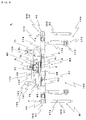
- the tilting block M3 comprises the tilting element 2, including a main tilting part 30 having a main tilting element 31, and an auxiliary tilting part 40.
- the main tilting part 30 is constructed by the planetary gear unit 4 as a central component.
- the planetary gear unit 4 includes the non-movable sun gear 5, and the right-side planetary gear 6R and the left-side planetary gear 6L symmetrically arranged to the sun gear 5.
- the auxiliary tilting part 40 includes a right-side auxiliary tilting section 41 having a right-side timing belt mechanism 42 driven by the right-side planetary gear 6R, and a left-side auxiliary tilting section 45 having a left-side timing belt mechanism 46 driven by the left-side planetary gear 6L.
- the sun gear 5 is set to the top-front of the central rising & falling shaft 3C stood on the center of the base 100. More concretely, a rear shaft 5a of the sun gear 5 projected backward is set to a bearing (not shown) arranged to the central rising & falling shaft 3C. On the other hand, a front shaft 5b of the sun gear 5 projected forward is fixed to the main tilting element 31, thereby the main tilting element 31 is able to be tilted around the front shaft 5b as tilting center.
- the central rising & falling shaft 3C has a connecting element connecting to the carrying element 120 at the bottom thereof, and has a connecting part connecting to the rear shaft 5a of the sun gear 5 set to the main tilting part 30 at the top thereof as described above. It is preferable that the central rising & falling shaft 3C is hollow in view of light-weight of the robot R.
- a reinforcing rib 3Ca is provided to the front-bottom of the central rising & falling shaft 3C in order to prevent the central rising & falling shaft 3C from bending forward when the central rising & falling shaft 3C is loaded.
- the right-side planetary gear 6R is set to the top of the right-side rising & falling shaft 3R stood at the right-side of the central rising & falling shaft 3C stood on the base 100. More concretely, a rear shaft 6Ra of the right-side planetary gear 6R projected backward is rotatably set to the top of the right-side rising & falling shaft 3R. On the other hand, the bottom of the front shaft 6Rb of the right-side planetary gear 6R projected forward is rotatably set to the main tilting element 31. Also, the top of the front shaft 6Rb is connected to a driving pulley 43 of the right-side timing belt mechanism 42 so as to be rotated integrally with the driving pulley 43.
- the right-side rising & falling shaft 3R is, for example, an electric cylinder including a right-side rising & falling body 3Ra, and a right-side actuator 3Rb rising and falling the right-side rising & falling shaft 3R.
- Bottom of an outer casing of the right-side rising & falling body 3Ra is tiltably connected to a connecting part 121 arranged on the carrying element 120.
- the bottom of the outer casing of the right-side rising & falling body 3Ra is connected by pin-joint.
- the right-side actuator 3Rb rising and falling the right-side rising & falling shaft 3R is connected to the right-side rising & falling body 3Ra so as for the right-side rising & falling body 3Ra is to be tilted.
- the left-side planetary gear 6L is set to the top of the left-side rising & falling shaft 3L stood at the left-side of the central rising & falling shaft 3C stood on the base 100. More concretely, a rear shaft 6La of the left-side planetary gear 6L projected backward is rotatably set to the top of the left-side riding & falling shaft 3L. On the other hand, the bottom of the front shaft 6Lb of the left-side planetary gear projected forward is rotatably set to the main tilting element 31. Also, the top of the front shaft 6Lb is connected to a driving pulley 47 of the left-side timing belt mechanism 46 so as to be rotated integrally with the driving pulley 47.
- the left-side rising & falling shaft 3L similar to the right-side rising & falling shaft 3R, includes a left-side rising & falling body 3La, and a left-side actuator 3Lb rising and falling the left-side rising & falling shaft 3L.
- Bottom of an outer casing of the left-side rising & falling body 3La is tiltably connected to a connecting part 121 arranged on the carrying element 120.
- the bottom of the outer casing of the left-side rising & falling body 3La is connected by pin-joint.
- the left-side actuator 3Lb rising & falling the left-side rising & falling shaft 3L is connected to the left-side rising & falling body 3La so as for the left-side rising & falling body 3La is to be rotated.
- the main tilting element 31 is a rectangular box 32, and houses the right-side timing belt mechanism 42 right-side thereof and the left-side timing belt mechanism 46 left-side thereof.
- sun gear 5 the front shaft 6Rb of the right-side planetary gear 6R and the front shaft 6Lb of the left-side planetary gear 6L are connected to the rear face 32a of the box 32.
- the right-end of the box 32 is equipped with a right-side auxiliary tilting element 44 of the right-side auxiliary tilting section 41 and the left-end of the box 32 is equipped with a left-side auxiliary tilting element 48 of the left-side auxiliary tilting section 45.
- the right-side auxiliary tilting element 44 and the left-side auxiliary tilting element 48 have the same construction except that they are bilateral symmetry, herein, the right-side auxiliary tilting element 44 is described and the description of the left-side auxiliary tilting element 48 is omitted.
- the right-side auxiliary tilting element 44 includes a driven pulley 43b driven by the driving pulley 43 through the timing belt 43a, a rear connecting piece 44a and a front connecting piece 44b connected to the rear shaft and the front shaft of the driven pulley 43b respectively, and a right-arm holding part 44c supported by the rear connecting piece 44a and the front connecting piece 44b.
- the rear connecting piece 44a and the front connecting piece 44b are connected to the rear shaft and the front shaft of the driven pulley 43b so that the rear connecting piece 44a and the front connecting piece 44b are rotated together with the driven pulley 43b.
- the front shaft and the rear shaft of the driven pulley 43b are rotatably supported by the end of the front part 32b and the end of the rear face 32a of the box 32 respectively.
- the front shaft and the rear shaft of the driven pulley 43b are rotatably supported through bearings.
- the timing belt 43a is provided with a tension adjuster in order to prevent the timing belt 43a from loosing. It is preferable that any known structure is able to be adopted as the tension adjuster. Namely, there is no limitation to the construction of the tension adjuster.
- the right-arm holding part 44c has a through-hole formed back and forth direction for the right-side arm element 21 to be inserted.
- the right-side arm element 21 is a hollow cylinder of which length is adjusted so that the right-side arm element 21 is projected forward from the robot R at prescribed distance, and a brim is formed at the rear end thereof to prevent the right-side arm element 21 from slipping off.
- the left-side arm element 22 has similar construction and is formed a brim at the rear end thereof.
- Such construction is acceptable for the right-side arm element 21 and the left-side arm element 22.
- the right-side arm element 21 is inserted so as to be moved freely backward and forward and that stopping groove 21a is ring-likely formed about midway thereof.
- the right-arm holding part 44c of the right-side auxiliary tilting element 44 is provided with a locking piece of a locking mechanism, for example, a latch locking mechanism F to be entered into the groove 21a so that the right-side arm element 21 is locked.
- the right-side arm element 21 and the left-side arm element 22 are constructed as such, it becomes easy for the right-side arm element 21 and the left-side arm element 22 are inserted into holding parts 61 of a custom care sheet 60 described later.
- the tilting block M3 is constructed as such, for example, the right-side of the main tilting part 30 is tilted up by synchronously raising the right-side rising & falling shaft 3R and falling the left-side rising & falling shaft 3L. Namely, the main tilting element 31 is inclined right-side up.
- the right-side planetary gear 6R and the left-side planetary gear 6L are rotated, and the right-side planetary gear 6R and the left-side planetary gear 6L are held by the rear face 32a of the box 32 composing the main tilting element 31, the right-side planetary gear 6R and the left-side planetary gear 6L are rotated in the same direction.
- Fig.9 shows one example of the custom care sheet 60.
- the custom care sheet 60 has cylindrical holding parts 61 at both end thereof.
- the right-side arm element 21 of the robot R is inserted into one of the holding part 61 and the left-side arm element 22 of the robot R is inserted into the other of the holding part 61.
- the holding part 61 comprises a base layer 62, a cushion layer 63 made of cushioned material arranged outside of the base layer 62 and a surface layer 64 made of synthetic resin sheet.
- Fig.10 shows the robot R is covered with a decorative cover.
- the decorative cover C includes a base cover C1 covering the base 100, a body cover C2 covering the central rising & falling shaft 3C, the right-side rising & falling shaft 3R and the left-side rising & falling shaft 3L, a main tilting element cover C3 covering the main tilting element 31, a right-side auxiliary tilting section cover C4 covering the right-side auxiliary tilting section 41, and a left-side auxiliary tilting section cover C6 covering the left-side auxiliary tilting section 45.
- the right-side arm element 21 is inserted into one of the holding parts 61 and the left-side arm element 22 is inserted into the other of the holding parts 61 of the custom care sheet 60 on which a care receiver is laid, and then the robot R is moved backward in condition that the care receiver is raised above the bed by raising the right-side rising & falling shaft 3R and the left-side using & falling shaft 3L synchronously. Thereafter, the main tilting element 31 is tilted so as for the head of the care receiver is moved upward, and then the care receiver is transferred to a wheelchair by the caregiver keeping such posture. Namely, the care receiver is able to be transferred to a wheelchair by one caregiver alone.
- the operating block M4 includes an operating levers 7, an operating panel 70, and a control device 200.
- the operating lever 7 has an actuating command knob (actuating command means generating actuating command) 8 at the front end thereof which generates actuating command for rising & falling shafts 3.
- actuating command knob actuating command means generating actuating command
- the operating levers 7 includes a right-side lever 7R set at the right-side of the tilting block M3, and a left-side lever 7L set at the left-side of the tilting block M3.
- the front end of the right-side lever 7R is provided with an actuating command knob 8 generating actuating command, i.e. a right-side knob 8R
- the front end of the left-side lever 7L is provided with an actuating command knob 8 for actuating command means generating actuating command, i.e. a left-side knob 8L (refer to Fig.4 to Fig.7 ).
- the right-side knob 8R and the left-side knob 8L generate input signals for a signal input block 210 of the control device 200.
- the operating panel 70 includes a head position indicating switches (head position indicating means) 71 indicating position of a head, head position indicating lamps (head position indicating displays) 72 displaying position of the head in response to an indicating signal from the head position indicating switch (the head position indicating means) 71, an emergency stop switch 73.
- the head position indicating switches 71 include a right-side indicating switch 71R indicating that the head is positioned at the right-side, and a left-side indicating switch 71L indicating that the head is positioned at the left-side.
- the head position indicating lamps 72 include a right-side indicating lamp 72R indicating that the head is positioned at the right-side, and a left-side lamp 72L indicating that the head is positioned at the left-side.
- the head position indicating switches 71 namely the right-side indicating switch 71R. and the left-side indicating switch 71L generate input signals for the signal input block 210 of the control device 200.
- a circuit of the right-side indicating switch 71R and left-side indicating switch 71L is made so that the other is turned off when one of them is turned on.
- the control device 200 is provided with the signal input block 210, an input signal managing block 220, a memory block 230, an arithmetic processing block 240, an electric current command generating block 250, and a signal output block 260 as main components.
- the control device 200 constructed as such is composed of a microcomputer installed programs performing functions described later.
- a circuit of the control device 200 is shown in Fig.14 .
- Signals from the actuating command knobs (the actuating command means) 8 generating actuating commands for rising & falling shafts 3 set to the robot R, the switches 71, and the acceleration sensor (acceleration detecting means) are inputted into the signal input block 210, and then inputted signals are outputted to the input signal managing block 220 and/or the memory block 230.
- the acceleration sensor is a three dimensional sensor.
- the acceleration sensor is not limited to the three dimensional sensor, any sensor which calculates at least tilt angle of the tilting block M3 based on acceleration thereof is acceptable.
- the three dimensional sensor not shown in the drawings, is set on the center of the top of the main tilting element 31.
- the input signal managing block 220 manages input signals inputted from the signal input block 210 and outputs the signals to the arithmetic processing block 240. As shown in Fig.15 , the input signal managing block 220 has polarity discriminating means 222 discriminating the polarity of the actuating command, and comparing means 224 comparing the amplitude of the absolute value of the actuating command and deciding the actuating command output to the arithmetic processing block 240, and head position discriminating means 226 discriminating head position.
- the polarity discriminating means 222 discriminates the polarity of the actuating commands from the right-side knob 8R and the left-side knob 8L, and decides raising or falling of the right-side rising & falling shaft 3R and the left-side rising & falling shaft 3L, thereafter the polarity discriminating means 222 outputs the decision to the arithmetic processing block 240.
- the polarity discriminating means 222 outputs raising commands for the right-side rising & falling shaft 3R and the left-side rising & falling shaft 3L.
- the polarity discriminating means 222 outputs falling commands for the right-side rising & falling shaft 3R and the left-side rising & falling shaft 3L.
- the polarity discriminating means 222 When the polarity of the actuating command from the right-side knob 8R is plus and the polarity of the actuating command from the left-side knob 8L is minus, the polarity discriminating means 222 outputs a raising command for the right-side rising & falling shaft 3R, while the polarity discriminating means 222 outputs a falling command for the left-side rising & falling shaft 3L.
- the polarity discriminating means 222 when the polarity of the actuating command from the right-side knob 8R is minus and the polarity of the actuating command from the left-side knob 8L is plus, the polarity discriminating means 222 outputs a falling command for the right-side rising & falling shaft 3R, while the polarity discriminating means 222 outputs a raising command for the left-side rising & falling shaft 3L.
- the comparing means 224 compares the amplitude of absolute value of the actuating command from the right-side knob 8R and the amplitude of absolute value of the actuating command from the left-side knob 8L, and then outputs the small one as the actuating command (the decided actuating command). Therefore, when either the actuating command from the right-side knob 8R or the actuating command from the left-side knob 8L is not inputted, rising & falling or tilting are not carried out because the decided actuating command becomes zero. As a result, the operation is carried out safely.
- the head position discriminating means 226 discriminates that the head position is the right-side or the left-side based on a signal from the head position indicating switch 71, and then the decision is outputted to the arithmetic processing block 240. Namely, the head position discriminating means 226 outputs a command indicating the head is the right-side based on the signal from the right-side indicating switch 71R to the arithmetic processing block 240, and the head position discriminating means 226 outputs a command indicating the head is left-side based on the signal from the left-side indicating switch 71L to the arithmetic processing block 240.
- the memory block 230 stores signals from the signal input block 210 and date for range of movement of the tilting block M3.
- the arithmetic processing block 240 processes based on signals inputted from the input signal managing block 220 and data stored in the memory block 230, thereafter the arithmetic processing block 240 outputs the result to the electric current command generating block 250, for example, as command for speed.
- the arithmetic processing block 240 includes a tilting processing section 242.
- the arithmetic processing block 240 outputs the processed raising or falling speed to the electric current command generating block 250, for example, as command for speed.
- the tilting processing section 242 having tilting speed command generating means (tilting command generating means) 244 and limit processing means 245 processes the following arithmetic processing:
- the limit processing means 245 performs limiting processing for the speed command signal generated by the tilting speed command generating means 244 as follows:
- the limit processing means 245 performs limiting processing for the speed command signal generated by the tilting speed command generating means 244 as follows:
- the electric current command generating block 250 generates electric current commands for the right-side rising & falling shaft 3R and the left-side rising & falling shaft 3L based on the speed command signals from the arithmetic processing block 240, and then outputs them to the signal output block 260.
- generation of the electric current commands are made by known method using the necessary data for generation of electric current commands stored in the memory block 230.
- the tilting block M3 is tilted by simple handling of only turning the right-side knob 8R set at the front end of the right-side operating lever 7R and the left-side knob 8L set at the front end of the left-side operating lever 7L, caregivers are not required to lift up care receivers from beds and the burden of caregivers are lightened. For example, the lower back pain so-called the occupational disorder is got rid of.
- auxiliary tilting elements 44, 48 are tilted by the timing belt mechanism 42, 46.
- the auxiliary tilting elements 44, 48 may be tilted by a chain mechanism.
- the actuating command means for the rising & falling shaft 3 are not limited to the embodiment, and numerous variants are possible.
- the actuating command means for the rising & falling shaft 3 are not limited to the knob 8R arranged at the front end of the right-side lever 7R, and the knob 8L arranged at the front end of the left-side lever 7L, and any type of signal input means is acceptable.
- any suitable setting position of the signal input means is acceptable. It is possible for a force sensor to be joined the signal input means.
- the present invention is applicable for use in the care business and the robot industry.
Landscapes
- Health & Medical Sciences (AREA)
- General Health & Medical Sciences (AREA)
- Nursing (AREA)
- Engineering & Computer Science (AREA)
- Life Sciences & Earth Sciences (AREA)
- Animal Behavior & Ethology (AREA)
- Public Health (AREA)
- Veterinary Medicine (AREA)
- Robotics (AREA)
- Mechanical Engineering (AREA)
- Manipulator (AREA)
- Invalid Beds And Related Equipment (AREA)
Applications Claiming Priority (3)
| Application Number | Priority Date | Filing Date | Title |
|---|---|---|---|
| JP2013216861A JP6340709B2 (ja) | 2013-10-18 | 2013-10-18 | ロボット |
| JP2013258661A JP6539016B2 (ja) | 2013-12-13 | 2013-12-13 | 制御装置 |
| PCT/JP2014/057950 WO2015056460A1 (fr) | 2013-10-18 | 2014-03-14 | Robot |
Publications (3)
| Publication Number | Publication Date |
|---|---|
| EP3058921A1 true EP3058921A1 (fr) | 2016-08-24 |
| EP3058921A4 EP3058921A4 (fr) | 2017-06-14 |
| EP3058921B1 EP3058921B1 (fr) | 2019-12-11 |
Family
ID=52827915
Family Applications (1)
| Application Number | Title | Priority Date | Filing Date |
|---|---|---|---|
| EP14854784.7A Active EP3058921B1 (fr) | 2013-10-18 | 2014-03-14 | Robot pour transfert de patient |
Country Status (8)
| Country | Link |
|---|---|
| US (1) | US10045898B2 (fr) |
| EP (1) | EP3058921B1 (fr) |
| KR (1) | KR102197894B1 (fr) |
| CN (1) | CN105636567B (fr) |
| AU (1) | AU2014335557B2 (fr) |
| CA (1) | CA2920283C (fr) |
| DK (1) | DK3058921T3 (fr) |
| WO (1) | WO2015056460A1 (fr) |
Cited By (1)
| Publication number | Priority date | Publication date | Assignee | Title |
|---|---|---|---|---|
| CN108890660A (zh) * | 2018-07-17 | 2018-11-27 | 东莞市奇趣机器人科技有限公司 | 一种具有托运功能的服务型智能机器人 |
Families Citing this family (10)
| Publication number | Priority date | Publication date | Assignee | Title |
|---|---|---|---|---|
| US9901500B2 (en) * | 2015-07-10 | 2018-02-27 | Michael Nordvik | Lifting assembly |
| CN106137612A (zh) * | 2016-07-28 | 2016-11-23 | 江苏若博机器人科技有限公司 | 一种无线双核双轮驱动自由升降机器人电动病床控制器 |
| CN106074035A (zh) * | 2016-07-28 | 2016-11-09 | 江苏若博机器人科技有限公司 | 一种双核双轮驱动机器人电动病床控制系统 |
| CN105997392A (zh) * | 2016-07-28 | 2016-10-12 | 江苏若博机器人科技有限公司 | 一种无线双核双轮驱动机器人电动病床控制系统 |
| DE102016224627A1 (de) | 2016-12-09 | 2018-06-14 | Fresenius Medical Care Deutschland Gmbh | Hohlfasermembran mit verbesserter Trennleistung und Herstellung einer Hohlfasermembran mit verbesserter Trennleistung |
| CN107951566A (zh) * | 2017-12-27 | 2018-04-24 | 邱敏敏 | 一种精确定位开口的医疗手术机器人 |
| KR102148029B1 (ko) * | 2018-06-25 | 2020-08-26 | 엘지전자 주식회사 | 로봇 |
| KR102507726B1 (ko) | 2020-12-31 | 2023-03-09 | (주)맨엔텔 | 추락방지, 전동주행 및 중력보상 기능을 포함한 통합제어 및 이에 대한 모니터링이 가능한 이승 로봇 시스템 |
| WO2025101550A1 (fr) | 2023-11-07 | 2025-05-15 | Fresenius Medical Care Holdings, Inc. | Membrane à fibres creuses de petit diamètre et procédés de fabrication de celle-ci |
| WO2025101552A1 (fr) | 2023-11-07 | 2025-05-15 | Fresenius Medical Care Holdings, Inc. | Dialyseurs utilisant des membranes à fibres creuses de petit diamètre |
Family Cites Families (22)
| Publication number | Priority date | Publication date | Assignee | Title |
|---|---|---|---|---|
| EP0365455B1 (fr) * | 1988-10-18 | 1993-01-20 | Bernard Marchand | Appareil de manutention de patients |
| SE9000037D0 (sv) * | 1990-01-05 | 1990-01-05 | Sinpro Ab | Anordning foerlyftning och transport av objekt |
| US5084921A (en) * | 1991-01-18 | 1992-02-04 | Hicks Jr George W | Supine patient lift and transfer apparatus |
| JP2775028B2 (ja) * | 1995-04-11 | 1998-07-09 | 保 岸 | 介護用リフター |
| JPH09117478A (ja) * | 1995-10-25 | 1997-05-06 | Kyoei Process Kk | 介護用ミニトランスファ装置 |
| JPH09168566A (ja) * | 1995-12-18 | 1997-06-30 | Shinmeiwa Auto Eng Kk | 車椅子 |
| US5892180A (en) | 1997-02-03 | 1999-04-06 | Medcare Products, L.C. | Patient hoist and scale |
| JPH1156928A (ja) * | 1997-08-18 | 1999-03-02 | Takayoshi Noguchi | 抱起こし用介護台車 |
| JPH11137615A (ja) * | 1997-11-13 | 1999-05-25 | Takayoshi Noguchi | 抱起こし用車椅子 |
| JP2002136549A (ja) | 2000-11-06 | 2002-05-14 | Okuma Seisakusho:Kk | 介護用キャリア |
| FI117820B (fi) * | 2002-09-23 | 2007-03-15 | Tuomo Uusitalo | Potilaan siirtotuoli |
| JP2004223078A (ja) | 2003-01-24 | 2004-08-12 | Sanwa Denshi:Kk | 介護用リフト装置 |
| JP2009515560A (ja) | 2005-03-14 | 2009-04-16 | エルゴ アシスト テクノロジー リミテッド ライアビリティ カンパニー | 関連フレーム及びリフトカート付き患者移動システム |
| AU2006302675B2 (en) * | 2005-10-07 | 2012-05-24 | Conmedisys, Inc. | Patient lift and transfer device |
| US8214943B2 (en) | 2005-10-07 | 2012-07-10 | Conmedisys, Inc. | Steering system for patient transfer device |
| CN101568317A (zh) * | 2007-03-28 | 2009-10-28 | 松下电器产业株式会社 | 移乘辅助设备及具有多个支撑器机构的移乘辅助设备 |
| EP2259764A2 (fr) * | 2008-04-04 | 2010-12-15 | Ergo-Asyst Technology LLC | Dispositif multifonction de transfert de patient |
| US8401702B2 (en) | 2008-06-06 | 2013-03-19 | Panasonic Corporation | Robot, and control apparatus, control method, and control program for robot |
| JP2011172898A (ja) * | 2010-01-29 | 2011-09-08 | Nobuo Ueda | 介護用リフト |
| CN202386897U (zh) * | 2011-09-22 | 2012-08-22 | 天津市长亭假肢公司 | 手臂式护理移位机 |
| WO2014046292A1 (fr) * | 2012-09-19 | 2014-03-27 | マッスル株式会社 | Méthode de soins et robot de soins |
| US20150182403A1 (en) * | 2013-01-18 | 2015-07-02 | Yi-Je Lim | A Mobile Robotic Lifting and Transferring System for Bariatric Patients |
-
2014
- 2014-03-14 CA CA2920283A patent/CA2920283C/fr active Active
- 2014-03-14 WO PCT/JP2014/057950 patent/WO2015056460A1/fr not_active Ceased
- 2014-03-14 AU AU2014335557A patent/AU2014335557B2/en active Active
- 2014-03-14 EP EP14854784.7A patent/EP3058921B1/fr active Active
- 2014-03-14 US US15/021,721 patent/US10045898B2/en active Active
- 2014-03-14 DK DK14854784.7T patent/DK3058921T3/da active
- 2014-03-14 CN CN201480056908.2A patent/CN105636567B/zh active Active
- 2014-03-14 KR KR1020167007684A patent/KR102197894B1/ko active Active
Cited By (1)
| Publication number | Priority date | Publication date | Assignee | Title |
|---|---|---|---|---|
| CN108890660A (zh) * | 2018-07-17 | 2018-11-27 | 东莞市奇趣机器人科技有限公司 | 一种具有托运功能的服务型智能机器人 |
Also Published As
| Publication number | Publication date |
|---|---|
| EP3058921A4 (fr) | 2017-06-14 |
| US10045898B2 (en) | 2018-08-14 |
| CA2920283A1 (fr) | 2015-04-23 |
| AU2014335557B2 (en) | 2019-06-27 |
| KR102197894B1 (ko) | 2021-01-04 |
| DK3058921T3 (da) | 2020-02-24 |
| AU2014335557A1 (en) | 2016-03-03 |
| CA2920283C (fr) | 2020-07-14 |
| KR20160072098A (ko) | 2016-06-22 |
| WO2015056460A1 (fr) | 2015-04-23 |
| CN105636567A (zh) | 2016-06-01 |
| CN105636567B (zh) | 2018-10-09 |
| US20160228314A1 (en) | 2016-08-11 |
| EP3058921B1 (fr) | 2019-12-11 |
Similar Documents
| Publication | Publication Date | Title |
|---|---|---|
| EP3058921B1 (fr) | Robot pour transfert de patient | |
| US12377005B2 (en) | Patient support apparatus control systems | |
| US11723825B2 (en) | Lift assembly for patient support apparatus | |
| WO2004026211A1 (fr) | Lit mobile | |
| EP3512381B1 (fr) | Dispositifs de support d'enfant utilisant un matériau à maillage stratifié | |
| JP2010088786A (ja) | 移乗装置 | |
| KR102502756B1 (ko) | 틸팅 가능한 구조를 지닌 전동 휠체어 | |
| JP2010088799A (ja) | 車いす | |
| US11440601B2 (en) | Motor vehicle and method for operating a motor vehicle | |
| JP2012115603A (ja) | 移乗支援装置、移乗支援方法、及び保持具 | |
| JP6340709B2 (ja) | ロボット | |
| JP2010279582A (ja) | 移乗支援装置 | |
| JP2013009849A (ja) | 車椅子に備える姿勢制御機構 | |
| JP6539016B2 (ja) | 制御装置 | |
| KR20210043838A (ko) | 침상 환자 이송장치 | |
| JP2013090647A (ja) | 移乗支援装置及び移乗支援装置の制御方法 | |
| JPS6031749A (ja) | 身体不自由者移送装置 | |
| JP6361257B2 (ja) | 搬送補助装置 | |
| JP3066285U (ja) | 座席安定装置付車椅子 | |
| JP2023128689A (ja) | 車椅子 | |
| JP2017170017A (ja) | 移乗支援装置 | |
| JP2008161628A (ja) | 電動車椅子 | |
| JP2019097914A (ja) | 昇降ベッド |
Legal Events
| Date | Code | Title | Description |
|---|---|---|---|
| PUAI | Public reference made under article 153(3) epc to a published international application that has entered the european phase |
Free format text: ORIGINAL CODE: 0009012 |
|
| 17P | Request for examination filed |
Effective date: 20160331 |
|
| AK | Designated contracting states |
Kind code of ref document: A1 Designated state(s): AL AT BE BG CH CY CZ DE DK EE ES FI FR GB GR HR HU IE IS IT LI LT LU LV MC MK MT NL NO PL PT RO RS SE SI SK SM TR |
|
| AX | Request for extension of the european patent |
Extension state: BA ME |
|
| DAX | Request for extension of the european patent (deleted) | ||
| A4 | Supplementary search report drawn up and despatched |
Effective date: 20170515 |
|
| RIC1 | Information provided on ipc code assigned before grant |
Ipc: B25J 5/00 20060101ALN20170509BHEP Ipc: A61G 7/10 20060101AFI20170509BHEP Ipc: B25J 11/00 20060101ALN20170509BHEP |
|
| STAA | Information on the status of an ep patent application or granted ep patent |
Free format text: STATUS: EXAMINATION IS IN PROGRESS |
|
| 17Q | First examination report despatched |
Effective date: 20180808 |
|
| REG | Reference to a national code |
Ref country code: DE Ref legal event code: R079 Ref document number: 602014058385 Country of ref document: DE Free format text: PREVIOUS MAIN CLASS: A61G0005000000 Ipc: A61G0007100000 |
|
| GRAP | Despatch of communication of intention to grant a patent |
Free format text: ORIGINAL CODE: EPIDOSNIGR1 |
|
| STAA | Information on the status of an ep patent application or granted ep patent |
Free format text: STATUS: GRANT OF PATENT IS INTENDED |
|
| RIC1 | Information provided on ipc code assigned before grant |
Ipc: B25J 11/00 20060101ALN20190517BHEP Ipc: A61G 7/10 20060101AFI20190517BHEP Ipc: B25J 5/00 20060101ALN20190517BHEP |
|
| INTG | Intention to grant announced |
Effective date: 20190619 |
|
| GRAS | Grant fee paid |
Free format text: ORIGINAL CODE: EPIDOSNIGR3 |
|
| GRAA | (expected) grant |
Free format text: ORIGINAL CODE: 0009210 |
|
| STAA | Information on the status of an ep patent application or granted ep patent |
Free format text: STATUS: THE PATENT HAS BEEN GRANTED |
|
| AK | Designated contracting states |
Kind code of ref document: B1 Designated state(s): AL AT BE BG CH CY CZ DE DK EE ES FI FR GB GR HR HU IE IS IT LI LT LU LV MC MK MT NL NO PL PT RO RS SE SI SK SM TR |
|
| REG | Reference to a national code |
Ref country code: GB Ref legal event code: FG4D |
|
| REG | Reference to a national code |
Ref country code: CH Ref legal event code: EP |
|
| REG | Reference to a national code |
Ref country code: AT Ref legal event code: REF Ref document number: 1211433 Country of ref document: AT Kind code of ref document: T Effective date: 20191215 |
|
| REG | Reference to a national code |
Ref country code: DE Ref legal event code: R096 Ref document number: 602014058385 Country of ref document: DE |
|
| REG | Reference to a national code |
Ref country code: IE Ref legal event code: FG4D |
|
| REG | Reference to a national code |
Ref country code: DK Ref legal event code: T3 Effective date: 20200217 |
|
| REG | Reference to a national code |
Ref country code: NL Ref legal event code: MP Effective date: 20191211 |
|
| REG | Reference to a national code |
Ref country code: LT Ref legal event code: MG4D |
|
| PG25 | Lapsed in a contracting state [announced via postgrant information from national office to epo] |
Ref country code: LT Free format text: LAPSE BECAUSE OF FAILURE TO SUBMIT A TRANSLATION OF THE DESCRIPTION OR TO PAY THE FEE WITHIN THE PRESCRIBED TIME-LIMIT Effective date: 20191211 Ref country code: GR Free format text: LAPSE BECAUSE OF FAILURE TO SUBMIT A TRANSLATION OF THE DESCRIPTION OR TO PAY THE FEE WITHIN THE PRESCRIBED TIME-LIMIT Effective date: 20200312 Ref country code: NO Free format text: LAPSE BECAUSE OF FAILURE TO SUBMIT A TRANSLATION OF THE DESCRIPTION OR TO PAY THE FEE WITHIN THE PRESCRIBED TIME-LIMIT Effective date: 20200311 Ref country code: SE Free format text: LAPSE BECAUSE OF FAILURE TO SUBMIT A TRANSLATION OF THE DESCRIPTION OR TO PAY THE FEE WITHIN THE PRESCRIBED TIME-LIMIT Effective date: 20191211 Ref country code: LV Free format text: LAPSE BECAUSE OF FAILURE TO SUBMIT A TRANSLATION OF THE DESCRIPTION OR TO PAY THE FEE WITHIN THE PRESCRIBED TIME-LIMIT Effective date: 20191211 Ref country code: FI Free format text: LAPSE BECAUSE OF FAILURE TO SUBMIT A TRANSLATION OF THE DESCRIPTION OR TO PAY THE FEE WITHIN THE PRESCRIBED TIME-LIMIT Effective date: 20191211 Ref country code: BG Free format text: LAPSE BECAUSE OF FAILURE TO SUBMIT A TRANSLATION OF THE DESCRIPTION OR TO PAY THE FEE WITHIN THE PRESCRIBED TIME-LIMIT Effective date: 20200311 |
|
| PG25 | Lapsed in a contracting state [announced via postgrant information from national office to epo] |
Ref country code: RS Free format text: LAPSE BECAUSE OF FAILURE TO SUBMIT A TRANSLATION OF THE DESCRIPTION OR TO PAY THE FEE WITHIN THE PRESCRIBED TIME-LIMIT Effective date: 20191211 Ref country code: HR Free format text: LAPSE BECAUSE OF FAILURE TO SUBMIT A TRANSLATION OF THE DESCRIPTION OR TO PAY THE FEE WITHIN THE PRESCRIBED TIME-LIMIT Effective date: 20191211 |
|
| PG25 | Lapsed in a contracting state [announced via postgrant information from national office to epo] |
Ref country code: AL Free format text: LAPSE BECAUSE OF FAILURE TO SUBMIT A TRANSLATION OF THE DESCRIPTION OR TO PAY THE FEE WITHIN THE PRESCRIBED TIME-LIMIT Effective date: 20191211 |
|
| PG25 | Lapsed in a contracting state [announced via postgrant information from national office to epo] |
Ref country code: PT Free format text: LAPSE BECAUSE OF FAILURE TO SUBMIT A TRANSLATION OF THE DESCRIPTION OR TO PAY THE FEE WITHIN THE PRESCRIBED TIME-LIMIT Effective date: 20200506 Ref country code: ES Free format text: LAPSE BECAUSE OF FAILURE TO SUBMIT A TRANSLATION OF THE DESCRIPTION OR TO PAY THE FEE WITHIN THE PRESCRIBED TIME-LIMIT Effective date: 20191211 Ref country code: CZ Free format text: LAPSE BECAUSE OF FAILURE TO SUBMIT A TRANSLATION OF THE DESCRIPTION OR TO PAY THE FEE WITHIN THE PRESCRIBED TIME-LIMIT Effective date: 20191211 Ref country code: EE Free format text: LAPSE BECAUSE OF FAILURE TO SUBMIT A TRANSLATION OF THE DESCRIPTION OR TO PAY THE FEE WITHIN THE PRESCRIBED TIME-LIMIT Effective date: 20191211 Ref country code: NL Free format text: LAPSE BECAUSE OF FAILURE TO SUBMIT A TRANSLATION OF THE DESCRIPTION OR TO PAY THE FEE WITHIN THE PRESCRIBED TIME-LIMIT Effective date: 20191211 Ref country code: RO Free format text: LAPSE BECAUSE OF FAILURE TO SUBMIT A TRANSLATION OF THE DESCRIPTION OR TO PAY THE FEE WITHIN THE PRESCRIBED TIME-LIMIT Effective date: 20191211 |
|
| PG25 | Lapsed in a contracting state [announced via postgrant information from national office to epo] |
Ref country code: SM Free format text: LAPSE BECAUSE OF FAILURE TO SUBMIT A TRANSLATION OF THE DESCRIPTION OR TO PAY THE FEE WITHIN THE PRESCRIBED TIME-LIMIT Effective date: 20191211 Ref country code: IS Free format text: LAPSE BECAUSE OF FAILURE TO SUBMIT A TRANSLATION OF THE DESCRIPTION OR TO PAY THE FEE WITHIN THE PRESCRIBED TIME-LIMIT Effective date: 20200411 Ref country code: SK Free format text: LAPSE BECAUSE OF FAILURE TO SUBMIT A TRANSLATION OF THE DESCRIPTION OR TO PAY THE FEE WITHIN THE PRESCRIBED TIME-LIMIT Effective date: 20191211 |
|
| REG | Reference to a national code |
Ref country code: DE Ref legal event code: R097 Ref document number: 602014058385 Country of ref document: DE |
|
| REG | Reference to a national code |
Ref country code: AT Ref legal event code: MK05 Ref document number: 1211433 Country of ref document: AT Kind code of ref document: T Effective date: 20191211 |
|
| PLBE | No opposition filed within time limit |
Free format text: ORIGINAL CODE: 0009261 |
|
| STAA | Information on the status of an ep patent application or granted ep patent |
Free format text: STATUS: NO OPPOSITION FILED WITHIN TIME LIMIT |
|
| PG25 | Lapsed in a contracting state [announced via postgrant information from national office to epo] |
Ref country code: MC Free format text: LAPSE BECAUSE OF FAILURE TO SUBMIT A TRANSLATION OF THE DESCRIPTION OR TO PAY THE FEE WITHIN THE PRESCRIBED TIME-LIMIT Effective date: 20191211 |
|
| REG | Reference to a national code |
Ref country code: CH Ref legal event code: PL |
|
| 26N | No opposition filed |
Effective date: 20200914 |
|
| PG25 | Lapsed in a contracting state [announced via postgrant information from national office to epo] |
Ref country code: SI Free format text: LAPSE BECAUSE OF FAILURE TO SUBMIT A TRANSLATION OF THE DESCRIPTION OR TO PAY THE FEE WITHIN THE PRESCRIBED TIME-LIMIT Effective date: 20191211 Ref country code: AT Free format text: LAPSE BECAUSE OF FAILURE TO SUBMIT A TRANSLATION OF THE DESCRIPTION OR TO PAY THE FEE WITHIN THE PRESCRIBED TIME-LIMIT Effective date: 20191211 |
|
| REG | Reference to a national code |
Ref country code: BE Ref legal event code: MM Effective date: 20200331 |
|
| PG25 | Lapsed in a contracting state [announced via postgrant information from national office to epo] |
Ref country code: LU Free format text: LAPSE BECAUSE OF NON-PAYMENT OF DUE FEES Effective date: 20200314 |
|
| PG25 | Lapsed in a contracting state [announced via postgrant information from national office to epo] |
Ref country code: LI Free format text: LAPSE BECAUSE OF NON-PAYMENT OF DUE FEES Effective date: 20200331 Ref country code: CH Free format text: LAPSE BECAUSE OF NON-PAYMENT OF DUE FEES Effective date: 20200331 Ref country code: IE Free format text: LAPSE BECAUSE OF NON-PAYMENT OF DUE FEES Effective date: 20200314 |
|
| PG25 | Lapsed in a contracting state [announced via postgrant information from national office to epo] |
Ref country code: PL Free format text: LAPSE BECAUSE OF FAILURE TO SUBMIT A TRANSLATION OF THE DESCRIPTION OR TO PAY THE FEE WITHIN THE PRESCRIBED TIME-LIMIT Effective date: 20191211 Ref country code: BE Free format text: LAPSE BECAUSE OF NON-PAYMENT OF DUE FEES Effective date: 20200331 |
|
| PG25 | Lapsed in a contracting state [announced via postgrant information from national office to epo] |
Ref country code: TR Free format text: LAPSE BECAUSE OF FAILURE TO SUBMIT A TRANSLATION OF THE DESCRIPTION OR TO PAY THE FEE WITHIN THE PRESCRIBED TIME-LIMIT Effective date: 20191211 Ref country code: MT Free format text: LAPSE BECAUSE OF FAILURE TO SUBMIT A TRANSLATION OF THE DESCRIPTION OR TO PAY THE FEE WITHIN THE PRESCRIBED TIME-LIMIT Effective date: 20191211 Ref country code: CY Free format text: LAPSE BECAUSE OF FAILURE TO SUBMIT A TRANSLATION OF THE DESCRIPTION OR TO PAY THE FEE WITHIN THE PRESCRIBED TIME-LIMIT Effective date: 20191211 |
|
| PG25 | Lapsed in a contracting state [announced via postgrant information from national office to epo] |
Ref country code: MK Free format text: LAPSE BECAUSE OF FAILURE TO SUBMIT A TRANSLATION OF THE DESCRIPTION OR TO PAY THE FEE WITHIN THE PRESCRIBED TIME-LIMIT Effective date: 20191211 |
|
| PGFP | Annual fee paid to national office [announced via postgrant information from national office to epo] |
Ref country code: GB Payment date: 20260202 Year of fee payment: 13 |
|
| PGFP | Annual fee paid to national office [announced via postgrant information from national office to epo] |
Ref country code: DE Payment date: 20260128 Year of fee payment: 13 Ref country code: DK Payment date: 20260313 Year of fee payment: 13 |
|
| PGFP | Annual fee paid to national office [announced via postgrant information from national office to epo] |
Ref country code: IT Payment date: 20260220 Year of fee payment: 13 |
|
| PGFP | Annual fee paid to national office [announced via postgrant information from national office to epo] |
Ref country code: FR Payment date: 20260209 Year of fee payment: 13 |