EP3062364A1 - Batteriepack - Google Patents
Batteriepack Download PDFInfo
- Publication number
- EP3062364A1 EP3062364A1 EP16157333.2A EP16157333A EP3062364A1 EP 3062364 A1 EP3062364 A1 EP 3062364A1 EP 16157333 A EP16157333 A EP 16157333A EP 3062364 A1 EP3062364 A1 EP 3062364A1
- Authority
- EP
- European Patent Office
- Prior art keywords
- battery pack
- cell holder
- fume discharge
- connection
- tabs
- Prior art date
- Legal status (The legal status is an assumption and is not a legal conclusion. Google has not performed a legal analysis and makes no representation as to the accuracy of the status listed.)
- Granted
Links
Images





Classifications
-
- H—ELECTRICITY
- H01—ELECTRIC ELEMENTS
- H01M—PROCESSES OR MEANS, e.g. BATTERIES, FOR THE DIRECT CONVERSION OF CHEMICAL ENERGY INTO ELECTRICAL ENERGY
- H01M50/00—Constructional details or processes of manufacture of the non-active parts of electrochemical cells other than fuel cells, e.g. hybrid cells
- H01M50/20—Mountings; Secondary casings or frames; Racks, modules or packs; Suspension devices; Shock absorbers; Transport or carrying devices; Holders
- H01M50/233—Mountings; Secondary casings or frames; Racks, modules or packs; Suspension devices; Shock absorbers; Transport or carrying devices; Holders characterised by physical properties of casings or racks, e.g. dimensions
- H01M50/24—Mountings; Secondary casings or frames; Racks, modules or packs; Suspension devices; Shock absorbers; Transport or carrying devices; Holders characterised by physical properties of casings or racks, e.g. dimensions adapted for protecting batteries from their environment, e.g. from corrosion
-
- H—ELECTRICITY
- H01—ELECTRIC ELEMENTS
- H01M—PROCESSES OR MEANS, e.g. BATTERIES, FOR THE DIRECT CONVERSION OF CHEMICAL ENERGY INTO ELECTRICAL ENERGY
- H01M50/00—Constructional details or processes of manufacture of the non-active parts of electrochemical cells other than fuel cells, e.g. hybrid cells
- H01M50/50—Current conducting connections for cells or batteries
- H01M50/502—Interconnectors for connecting terminals of adjacent batteries; Interconnectors for connecting cells outside a battery casing
-
- H—ELECTRICITY
- H01—ELECTRIC ELEMENTS
- H01M—PROCESSES OR MEANS, e.g. BATTERIES, FOR THE DIRECT CONVERSION OF CHEMICAL ENERGY INTO ELECTRICAL ENERGY
- H01M50/00—Constructional details or processes of manufacture of the non-active parts of electrochemical cells other than fuel cells, e.g. hybrid cells
- H01M50/10—Primary casings; Jackets or wrappings
- H01M50/102—Primary casings; Jackets or wrappings characterised by their shape or physical structure
- H01M50/103—Primary casings; Jackets or wrappings characterised by their shape or physical structure prismatic or rectangular
-
- H—ELECTRICITY
- H01—ELECTRIC ELEMENTS
- H01M—PROCESSES OR MEANS, e.g. BATTERIES, FOR THE DIRECT CONVERSION OF CHEMICAL ENERGY INTO ELECTRICAL ENERGY
- H01M50/00—Constructional details or processes of manufacture of the non-active parts of electrochemical cells other than fuel cells, e.g. hybrid cells
- H01M50/10—Primary casings; Jackets or wrappings
- H01M50/147—Lids or covers
- H01M50/148—Lids or covers characterised by their shape
- H01M50/15—Lids or covers characterised by their shape for prismatic or rectangular cells
-
- H—ELECTRICITY
- H01—ELECTRIC ELEMENTS
- H01M—PROCESSES OR MEANS, e.g. BATTERIES, FOR THE DIRECT CONVERSION OF CHEMICAL ENERGY INTO ELECTRICAL ENERGY
- H01M50/00—Constructional details or processes of manufacture of the non-active parts of electrochemical cells other than fuel cells, e.g. hybrid cells
- H01M50/20—Mountings; Secondary casings or frames; Racks, modules or packs; Suspension devices; Shock absorbers; Transport or carrying devices; Holders
- H01M50/204—Racks, modules or packs for multiple batteries or multiple cells
- H01M50/207—Racks, modules or packs for multiple batteries or multiple cells characterised by their shape
- H01M50/211—Racks, modules or packs for multiple batteries or multiple cells characterised by their shape adapted for pouch cells
-
- H—ELECTRICITY
- H01—ELECTRIC ELEMENTS
- H01M—PROCESSES OR MEANS, e.g. BATTERIES, FOR THE DIRECT CONVERSION OF CHEMICAL ENERGY INTO ELECTRICAL ENERGY
- H01M50/00—Constructional details or processes of manufacture of the non-active parts of electrochemical cells other than fuel cells, e.g. hybrid cells
- H01M50/20—Mountings; Secondary casings or frames; Racks, modules or packs; Suspension devices; Shock absorbers; Transport or carrying devices; Holders
- H01M50/256—Carrying devices, e.g. belts
-
- H—ELECTRICITY
- H01—ELECTRIC ELEMENTS
- H01M—PROCESSES OR MEANS, e.g. BATTERIES, FOR THE DIRECT CONVERSION OF CHEMICAL ENERGY INTO ELECTRICAL ENERGY
- H01M50/00—Constructional details or processes of manufacture of the non-active parts of electrochemical cells other than fuel cells, e.g. hybrid cells
- H01M50/30—Arrangements for facilitating escape of gases
-
- H—ELECTRICITY
- H01—ELECTRIC ELEMENTS
- H01M—PROCESSES OR MEANS, e.g. BATTERIES, FOR THE DIRECT CONVERSION OF CHEMICAL ENERGY INTO ELECTRICAL ENERGY
- H01M50/00—Constructional details or processes of manufacture of the non-active parts of electrochemical cells other than fuel cells, e.g. hybrid cells
- H01M50/30—Arrangements for facilitating escape of gases
- H01M50/35—Gas exhaust passages comprising elongated, tortuous or labyrinth-shaped exhaust passages
-
- H—ELECTRICITY
- H01—ELECTRIC ELEMENTS
- H01M—PROCESSES OR MEANS, e.g. BATTERIES, FOR THE DIRECT CONVERSION OF CHEMICAL ENERGY INTO ELECTRICAL ENERGY
- H01M50/00—Constructional details or processes of manufacture of the non-active parts of electrochemical cells other than fuel cells, e.g. hybrid cells
- H01M50/50—Current conducting connections for cells or batteries
-
- H—ELECTRICITY
- H01—ELECTRIC ELEMENTS
- H01M—PROCESSES OR MEANS, e.g. BATTERIES, FOR THE DIRECT CONVERSION OF CHEMICAL ENERGY INTO ELECTRICAL ENERGY
- H01M50/00—Constructional details or processes of manufacture of the non-active parts of electrochemical cells other than fuel cells, e.g. hybrid cells
- H01M50/50—Current conducting connections for cells or batteries
- H01M50/502—Interconnectors for connecting terminals of adjacent batteries; Interconnectors for connecting cells outside a battery casing
- H01M50/514—Methods for interconnecting adjacent batteries or cells
- H01M50/516—Methods for interconnecting adjacent batteries or cells by welding, soldering or brazing
-
- H—ELECTRICITY
- H01—ELECTRIC ELEMENTS
- H01M—PROCESSES OR MEANS, e.g. BATTERIES, FOR THE DIRECT CONVERSION OF CHEMICAL ENERGY INTO ELECTRICAL ENERGY
- H01M50/00—Constructional details or processes of manufacture of the non-active parts of electrochemical cells other than fuel cells, e.g. hybrid cells
- H01M50/50—Current conducting connections for cells or batteries
- H01M50/531—Electrode connections inside a battery casing
- H01M50/54—Connection of several leads or tabs of plate-like electrode stacks, e.g. electrode pole straps or bridges
-
- H—ELECTRICITY
- H01—ELECTRIC ELEMENTS
- H01M—PROCESSES OR MEANS, e.g. BATTERIES, FOR THE DIRECT CONVERSION OF CHEMICAL ENERGY INTO ELECTRICAL ENERGY
- H01M50/00—Constructional details or processes of manufacture of the non-active parts of electrochemical cells other than fuel cells, e.g. hybrid cells
- H01M50/50—Current conducting connections for cells or batteries
- H01M50/543—Terminals
- H01M50/547—Terminals characterised by the disposition of the terminals on the cells
- H01M50/55—Terminals characterised by the disposition of the terminals on the cells on the same side of the cell
-
- H—ELECTRICITY
- H01—ELECTRIC ELEMENTS
- H01M—PROCESSES OR MEANS, e.g. BATTERIES, FOR THE DIRECT CONVERSION OF CHEMICAL ENERGY INTO ELECTRICAL ENERGY
- H01M50/00—Constructional details or processes of manufacture of the non-active parts of electrochemical cells other than fuel cells, e.g. hybrid cells
- H01M50/50—Current conducting connections for cells or batteries
- H01M50/543—Terminals
- H01M50/552—Terminals characterised by their shape
- H01M50/553—Terminals adapted for prismatic, pouch or rectangular cells
-
- H—ELECTRICITY
- H01—ELECTRIC ELEMENTS
- H01M—PROCESSES OR MEANS, e.g. BATTERIES, FOR THE DIRECT CONVERSION OF CHEMICAL ENERGY INTO ELECTRICAL ENERGY
- H01M50/00—Constructional details or processes of manufacture of the non-active parts of electrochemical cells other than fuel cells, e.g. hybrid cells
- H01M50/50—Current conducting connections for cells or batteries
- H01M50/543—Terminals
- H01M50/564—Terminals characterised by their manufacturing process
- H01M50/566—Terminals characterised by their manufacturing process by welding, soldering or brazing
-
- H—ELECTRICITY
- H01—ELECTRIC ELEMENTS
- H01M—PROCESSES OR MEANS, e.g. BATTERIES, FOR THE DIRECT CONVERSION OF CHEMICAL ENERGY INTO ELECTRICAL ENERGY
- H01M50/00—Constructional details or processes of manufacture of the non-active parts of electrochemical cells other than fuel cells, e.g. hybrid cells
- H01M50/50—Current conducting connections for cells or batteries
- H01M50/569—Constructional details of current conducting connections for detecting conditions inside cells or batteries, e.g. details of voltage sensing terminals
-
- H—ELECTRICITY
- H01—ELECTRIC ELEMENTS
- H01M—PROCESSES OR MEANS, e.g. BATTERIES, FOR THE DIRECT CONVERSION OF CHEMICAL ENERGY INTO ELECTRICAL ENERGY
- H01M50/00—Constructional details or processes of manufacture of the non-active parts of electrochemical cells other than fuel cells, e.g. hybrid cells
- H01M50/10—Primary casings; Jackets or wrappings
- H01M50/172—Arrangements of electric connectors penetrating the casing
- H01M50/174—Arrangements of electric connectors penetrating the casing adapted for the shape of the cells
- H01M50/178—Arrangements of electric connectors penetrating the casing adapted for the shape of the cells for pouch or flexible bag cells
-
- Y—GENERAL TAGGING OF NEW TECHNOLOGICAL DEVELOPMENTS; GENERAL TAGGING OF CROSS-SECTIONAL TECHNOLOGIES SPANNING OVER SEVERAL SECTIONS OF THE IPC; TECHNICAL SUBJECTS COVERED BY FORMER USPC CROSS-REFERENCE ART COLLECTIONS [XRACs] AND DIGESTS
- Y02—TECHNOLOGIES OR APPLICATIONS FOR MITIGATION OR ADAPTATION AGAINST CLIMATE CHANGE
- Y02E—REDUCTION OF GREENHOUSE GAS [GHG] EMISSIONS, RELATED TO ENERGY GENERATION, TRANSMISSION OR DISTRIBUTION
- Y02E60/00—Enabling technologies; Technologies with a potential or indirect contribution to GHG emissions mitigation
- Y02E60/10—Energy storage using batteries
Definitions
- Embodiments of the invention relate to a battery pack.
- Secondary batteries are rechargeable. Secondary batteries are used as energy sources of devices such as mobile devices, electric vehicles, hybrid electric vehicles, electric bicycles, and uninterruptible power supplies. Single-cell secondary batteries or multi-cell secondary batteries (secondary battery packs) in which a plurality of battery cells are electrically connected are used according to the types of external devices using the secondary batteries.
- the present invention sets out to provide a secondary battery pack comprising a plurality of battery cells that are electrically combined using a connection tab having improved coupling characteristics without damaging a cell holder.
- Embodiments are directed to a battery pack including a battery cell including an electrode tab, a cell holder through which the electrode tab is inserted, a connection tab welded to the electrode tab and providing a welded portion above the cell holder, and a fume discharge groove located in a region of the cell holder under the welded portion.
- the fume discharge groove may extend across a bottom side of the connection tab.
- the fume discharge groove may be a channel that extends across a bottom side of the connection tab between first and second points of the cell holder.
- the fume discharge groove may extend to an outside of the cell holder.
- the cell holder may be rectangular shaped and may include a pair of parallel long sides and a pair of parallel short sides.
- the fume discharge groove may include a first fume discharge groove extending in a direction parallel to the long sides and a second fume discharge groove extending in a direction parallel to the short sides.
- the battery pack may include a plurality of battery cells.
- the first fume discharge groove may successively cross bottom sides of two or more connection tabs arranged in the direction parallel to the long sides.
- the battery cells may be arranged in the direction parallel to the short sides.
- the first and second fume discharge grooves may be connected to each other in a region of the connection tab or in a region close to the connection tab.
- the cell holder and the connection tab may include position aligning portions that provide alignment between the cell holder and the connection tab.
- the position aligning portions may include a protrusion extending upward from the cell holder toward the connection tab and a hole in the connection tab to receive the protrusion.
- a guide rib may be located on the cell holder to guide a sensing line.
- the sensing line may be a wire connected to the connection tab or the electrode tab to transmit information about a state of the battery cell.
- the battery pack may include a plurality of connection tabs. At least one of the connection tabs may include an output terminal extending to a lateral side of the cell holder.
- a threaded part may be coupleable to the output terminal to connect an output cable to the output terminal.
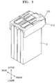
- FIG. 1 illustrates a view depicting a battery pack according to an embodiment of the invention.
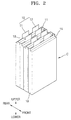
- FIG. 2 illustrates a perspective view of battery cells depicted in FIG. 1 .
- FIG. 3 illustrates an exploded perspective view of the battery pack depicted in FIG. 1 .
- the battery pack may include at least two battery cells C and a cell holder 110 to which the battery cells C are coupleable.
- the battery cells C may include lithium-ion battery cells.
- Each of the battery cells C may include an electrode assembly having a stacked structure formed by first and second electrode plates having different polarities and a separator disposed between the first and second electrode plates. A plurality of first and second electrode plates and a plurality of separators may be stacked in the electrode assembly to increase the output power and capacity of the battery cell C.
- the each of the battery cells C may include a case 13 to seal the electrode assembly.
- the battery cells C may be pouch type battery cells, each including a relatively flexible case 13 instead of a metal can.
- the battery cells C may include electrode tabs 10 electrically connected to the electrode assemblies (not shown) and extending outward from the cases 13.
- Each of the battery cells C may include first and second electrode tabs 11 and 12 respectively making electrical connection with the first and second electrode plates and thus having different polarities.
- the term "electrode tab(s) 10" refers to one or both of the first and second electrode tabs 11 and 12.
- the battery cells C may include terraces 15 from which the electrode tabs 10 outwardly extend.
- the battery cells C may be coupleable to the cell holder 110.
- the battery cells C may be coupleable to the cell holder 110 in such a manner that the electrode tabs 10 of the battery cells C are exposed on an upper surface of the cell holder 110.
- the cell holder 110 may support and hold the battery cells C.
- the battery cells C may be maintained at proper positions when inserted into the cell holder 110.
- the cell holder 110 may structurally combine the battery cells C into a single module.
- the cell holder 110 may include a plurality of tab holes 110' corresponding to the battery cells C.
- the electrode tabs 10 extending from the battery cells C may be inserted through the tab holes 110' and exposed to the outside.
- the tab holes 110' may be paired such that the first and second electrode tabs 11 and 12 extending from each of the battery cells C may be inserted through a pair of the tab holes 110'.
- the first and second electrode tabs 11 and 12 extending from one of the battery cells C may be inserted through a pair of the tab holes 110', and then the first and second electrode tabs 11 and 12 may be bent forward or backward in opposite directions to make electrical connection with neighboring battery cells C disposed in front and rear directions.
- Battery cells C neighboring each other in a front-to-rear direction may be electrically connected to each other through connection tabs 120 superposed on the first and second electrode tabs 11 and 12 of the battery cells.
- battery cells C arranged in the front-to-rear direction may be structurally modularized by the cell holder 110 and then may be electrically modularized by the connection tabs 120.
- connection tabs 120 may be superposed on the electrode tabs 10 that extend from the cell holder 110 through the tab holes 110'.
- the connection tabs 120 may be coupleable to the electrode tabs 10 by, for example, welding.
- connection tabs 120 may include pairs of first and second connection tabs 121 and 122. Each pair of first and second connection tabs 121 and 122 may be disposed on lower and upper sides of the electrode tabs 10 to place the electrode tabs 10 therebetween. As described above, when the electrode tabs 10 are sandwiched between the first and second connection tabs 121 and 122 of the connection tabs 120 disposed on the lower and upper sides of the electrode tabs 10, electric connection between the electrode tabs 10 and the connection tabs 120 may be made more smoothly. For example, the electric contact area between the connection tabs 120 and the electrode tabs 10 may be increased. Moreover, the coupling strength between the connection tabs 120 and the electrode tabs 10 may be improved.
- the electrode tabs 10 extending from the battery cells C may be inserted through the tab holes 110' of the cell holder 110 and tab holes 121' of the first connection tabs 121 and exposed on upper surfaces of the first connection tabs 121.
- the second connection tabs 122 may be superposed on the upper surfaces of the first connection tabs 121 on which the electrode tabs 10 are exposed.
- connection tabs 120 and the electrode tabs 10 may be coupled to each other by welding.
- the connection tabs 120 and the electrode tabs 10 may be coupled to each other by soldering.
- soldering is a manual process using a large amount of solder. Accordingly, the quality of soldering may not be uniform, and the coupling between the connection tabs 120 and the electrode tabs 10 could be broken at a weak point.
- solder were to scatter to another conductive part from a coupling portion, a short circuit could occur.
- the electrode tabs 10 could exhibit poor bonding characteristics.
- the electrode tabs 10 are formed of an aluminum material, bonding errors could arise due to galvanic corrosion. In this embodiment, however, welding is used. Thus, process automation may be possible, and coupling quality may be uniformly maintained without electrical connection errors or a short circuit.
- connection tabs 120 and the cell holder 110 may include position aligning portions 121 a, 122a, and 110a for position alignment therebetween.
- the position aligning portions 110a, 121 a, and 122a may include protrusions 110a1 formed on the cell holder 110 and holes 121a and 122a formed in the connection tabs 120 for receiving the protrusions 110a1.
- the connection tabs 120 may be disposed at proper positions. In this state, the connection tabs 120 may be aligned with the electrode tabs 10 exposed on the upper surface of the cell holder 110 and may be connected to the electrode tabs 10.
- connection tabs 120 may include the pairs of first and second connection tabs 121 and 122 disposed on the lower and upper sides of the electrode tabs 10.
- the first and second connection tabs 121 and 122 to be superposed at the same position may be aligned with each other by coupling the first and second connection tabs 121 and 122 to the same protrusions 110a1 formed on the cell holder 110.
- the position aligning portions 110a, 121a, and 122a may have suitable shapes such that the position aligning portions 110a, 121a, and 122a may regulate relative assembling positions of the connection tabs 120 and the cell holder 110.
- the position aligning portions 110a, 121a, and 122a may include ribs 110a2 formed on the cell holder 110.
- the ribs 110a2 may extend on the cell holder 110 in one direction, and edges of the connection tabs 120 may be inserted between the ribs 110a2.
- the ribs 110a2 may include ribs extending in different directions and aligned with sides of the connection tabs 120.
- the cell holder 110 may include support ribs 115 protruding toward the battery cells C.
- the support ribs 115 may protrude downwardly toward the battery cells C.
- the support ribs 115 may support portions of the battery cells C, for example, the terraces 15 of the battery cells C.
- the support ribs 115 may help to prevent the terraces 15 of the battery cells C from colliding with a lower surface of the cell holder 110 and may maintain a proper distance between the cell holder 110 and the terraces 15 of the battery cells C, thereby helping to prevent the electrode tabs 10 from being damaged during a welding process.
- the support ribs 115 may protrude from the cell holder 110 toward the terraces 15 of the battery cells C. Accordingly, the coupling height of the battery cells C may be regulated to maintain a proper distance between the cell holder 110 and the battery cells C.
- the cell holder 110 may be less likely to be damaged by collision, and the electrode tabs 10 may be less likely to be damaged during welding.
- FIG. 4 is a perspective view illustrating output terminals 130.
- connection tabs 120 electrically connecting pairs of the electrode tabs 10 may include the output terminals 130.
- a connection tab 120 disposed at a forefront position and a connection tab 120 disposed at a rearmost position may include the output terminals 130.
- the output terminals 130 and the connection tabs 120 may be formed as one-piece parts extending from the upper surface of the cell holder 110 to form a lateral side of the cell holder 110.
- Output cables 155 (only one is shown in FIG. 4 ) may be connected to the output terminals 130 to form a charging and discharging current path.
- the output cables 155 may be connected to the output terminals 130 using threaded parts 150.
- a connection process may be simply performed within a short time.
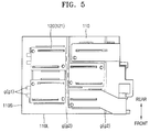
- FIGS. 5 and 6 illustrate a plan view and a perspective view of an upper side of the cell holder 110 for explaining fume discharge grooves (g). For clarity of illustration, elements of the cell holder 110 other than the fume discharge grooves (g) are not shown in FIG. 6 .
- the fume discharge grooves (g) may be formed in the cell holder 110.
- the fume discharge grooves (g) may be formed to discharge welding gas and contaminants when the connection tabs 120 and the electrode tabs 10 are welded.
- the term "fumes" may refer to welding gas and contaminants generated as byproducts during a welding process.
- the fume discharge grooves (g) may be formed under welded portions (coupling portions) between the connection tabs 120 and the electrode tabs 10.
- the fume discharge grooves (g) may be formed in regions overlapping the connection tabs 120 (regions under the connection tabs 120) or regions close to the connection tabs 120.
- the fume discharge grooves (g) may be channels extending from first points to second points of the cell holder 110.
- the fume discharge grooves (g) may be channels crossing bottom sides of the connection tabs 120 and extending away from the bottom sides of the connection tabs 120. In this case, fumes generated during welding of the connection tabs 120 may be easily discharged to the outside.
- the fume discharge grooves (g) may extend to the outside of the cell holder 110 such that fumes generated during welding may easily discharged to the outside of the cell holder 110.
- the fume discharge grooves (g) may extend on the cell holder 110 in two directions.
- the cell holder 110 may include a pair of parallel long sides 110L and a pair of parallel short sides 110S
- the fume discharge grooves (g) may include first and second fume discharge grooves g1 and g2 extending in parallel with the long sides 110L and the short sides 110S.
- the first and second fume discharge grooves g1 and g2 may be formed at a plurality of positions corresponding to the connection tabs 120.
- a plurality of battery cells C may be arranged along the short sides 110S of the cell holder 110 and coupled to the cell holder 110.
- the first fume discharge grooves g1 may extend across the connection tabs 120.
- the first fume discharge grooves g1 may extend across the connection tabs 120 in a direction parallel to the long sides 110L.
- the first fume discharge grooves g1 and the second fume discharge grooves g2 may extend in mutually crossing directions such that the first and second fume discharge grooves g1 and g2 may be connected to each other.
- each of the second fume discharge grooves g2 may extend to the outside of the cell holder 110.
- the second fume discharge grooves g2 may extend in parallel with the short sides 110S, and ends of the second fume discharge grooves g2 may reach the outside of the cell holder 110.
- the first and second fume discharge grooves g1 and g2 may extend in different directions and may meet each other in regions of the connection tabs 120 or regions close to the connection tabs 120.
- the first and second fume discharge grooves g1 and g2 may be connected to each other in regions close the connection tabs 120. In this case, when the connection tabs 120 are welded, fumes may be rapidly discharged in two directions.
- the fume discharge grooves (g) may extend across regions of the connection tabs 120 or regions close to the connection tabs 120.
- the terms “regions of the connection tabs 120" or “regions close to the connection tabs 120” may refer to welded portions between the connection tabs 120 and the electrode tabs 10 or regions close to the welded portions. If the fume discharge grooves (g) extend across the connection tabs 120, fumes may be efficiently discharged. In this case, however, if the connection tabs 120 and the electrode tabs 10 are suspended above the fume discharge grooves (g), a support area for a welding process could be reduced. Therefore, some of the fume discharge grooves (g) may be formed outside welding portions. For example, the second fume discharge grooves g2 may be formed at positions slightly away from the connection tabs 120.
- Fumes may be rapidly discharged through the fume discharge grooves (g) when the connection tabs 120 are welded. Accordingly, the connection tabs 120 may be properly welded. For example, if fumes were to accumulate in welded portions between the connection tabs 120 and the electrode tabs 10, the quality the welded portions could be lowered, and the cell holder 110 could be damaged by the fumes having a high temperature.
- the output power of the battery pack may be increased by increasing the number of battery cells C included in the battery pack.
- the battery pack may be expanded by repeatedly arranging unit packs, each being a group of battery cells C.
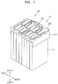
- FIG. 7 illustrates a view depicting a battery pack according to another embodiment of the invention.
- FIG. 8 illustrates an exploded perspective view of the battery pack depicted in FIG. 7 .
- the battery pack may include a first unit pack N1 and a second unit pack N2 coupleable to each other.
- the battery pack may be made up of only one of the first and second unit packs N1 and N2 or may be made up of the first and second unit packs N1 and N2 according to a desired output power or capacity level.
- the first and second unit packs N1 and N2 may have substantially the same structure.
- the first and second unit packs N1 and N2 having substantially the same structure may be connected together to double the output power or capacity of the battery pack.
- the first and second unit packs N1 and N2 may have substantially the same structure. Accordingly, various performance requirements may be flexibly handled.
- the battery pack may be constituted by a single unit pack such as the first unit pack N1 or the second unit pack N2 for applications requiring relatively low power levels or may be constituted by connecting the first and second unit packs N1 and N2 for applications requiring relatively high power levels.
- the battery pack may be constituted according to power requirements with one or more unit packs having substantially the same structure. Accordingly, the efficiency of processes for manufacturing the battery pack may be increased. Investments with respect to designs and production equipment for producing battery packs having different structures and output power levels may be avoided.
- the first and second unit packs N1 and N2 may have substantially the same structure.
- the expression “substantially the same structure” indicates that although the first and second unit packs N1 and N2 do not have completely the same structure, the first and second unit packs N1 and N2 have almost identical structures.
- the designs of the first and second unit packs N1 and N2 may be identical except for some parts such as expansion connection parts NC (described below).
- cell holders 210 may include expansion connection parts NC.
- the expansion connection parts NC may be used to connect the first and second unit packs N1 and N2.
- the expansion connection parts NC may be formed on edge portions or outer portions of the cell holders 210.
- the expansion connection parts NC of the first and second unit packs N1 and N2 may be coupleable to each other.
- the cell holder 210 of the first unit pack N1 may include expansion connection parts N1a and N1b to couple with the cell holder 210 of the second unit pack N2
- the cell holder 210 of the second unit pack N2 may include expansion connection parts N2a and N2b to couple with the cell holder 210 of the first unit pack N1.
- the cell holders 210 may include support ribs 215 protruding downwardly from the cell holders 210 for supporting terraces 15 of battery cells C.
- the support ribs 215 may be brought into direct contact with the terraces 15 of the battery cells C.
- Connection tabs 220 for electrically connecting the battery cells C may include first and second connection tabs 221 and 222.
- the first and second connection tabs 221 and 222 may be disposed on lower and upper sides of electrode tabs 10 of the battery cells C such that the electrode tabs 10 may be sandwiched between the first and second connection tabs 221 and 222.
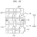
- FIGS. 9 and 10 illustrate a plan view and a perspective view of upper sides of the cell holders 210 for explaining fume discharge grooves (g). For clarity of illustration, elements of the cell holders 210 other than the fume discharge grooves (g) are not shown in FIG. 10 .
- the fume discharge grooves (g) may be formed in the cell holders 210.
- the fume discharge grooves (g) may be formed under welded portions (coupling portions) between the connection tabs 220 and the electrode tabs 10.
- the fume discharge grooves (g) may be formed in regions overlapping the connection tabs 220 (regions under the connection tabs 220) or regions close to the connection tabs 220.
- the fume discharge grooves (g) may be channels extending from first points to second points of the cell holders 210.
- the fume discharge grooves (g) may be channels crossing bottom sides of the connection tabs 220 and extending away from the bottom sides of the connection tabs 220.
- the fume discharge grooves (g) may extend to the outside of the cell holders 210 such that fumes generated during welding may easily discharged to the outside of the cell holders 210.
- the fume discharge grooves (g) may extend on the cell holders 210 in two directions.
- each of the cell holders 210 (that is, each of the cell holder 210 of the first unit pack N1 and the cell holder 210 of the second unit pack N2) may include a pair of parallel long sides 210L and a pair of parallel short sides 210S
- the fume discharge grooves (g) may include first and second fume discharge grooves g1 and g2 extending in parallel with the long sides 210L and the short sides 210S.
- the first and second fume discharge grooves g1 and g2 may be formed at a plurality of positions corresponding to the connection tabs 120.
- a plurality of battery cells C may be arranged along the short sides 110S of each of the cell holders 210 and coupled to each of the cell holders 210.
- a plurality of unit packs such as the first and second unit packs N1 and N2 may be coupled together according to a desired number of battery cells C of the battery pack.
- the battery pack may be configured to have a high degree of output power. If a large number of battery cells were to be coupled to one cell holder 210, it could be difficult to align the battery cells and the cell holder 210.
- unit packs each including a relatively small number of battery cells such as the first and second unit packs N1 and N2 according to embodiments are used, the battery pack may be easily assembled.
- the first fume discharge grooves g1 may extend across one or more of the connection tabs 220. At least one of both ends of each of the first fume discharge grooves g1 may extend to the outside of the cell holders 210.
- the first fume discharge grooves g1 may extend across two or more of the connection tabs 220 in a direction parallel to the long sides 210L, and ends of the first fume discharge grooves g1 may reach the outside of the cell holders 210.
- the second fume discharge grooves g2 may extend across the connection tabs 220. At least one of both ends of each of the second fume discharge grooves g2 may extend to the outside of the cell holders 210. For example, the second fume discharge grooves g2 may extend in parallel with the short sides 210S, and ends of the second fume discharge grooves g2 may reach the outside of the cell holders 210.
- the first and second fume discharge grooves g1 and g2 may extend in different directions and may meet each other in regions of the connection tabs 220 or in regions close the connection tabs 220. Accordingly, when the connection tabs 220 are welded, fumes may be rapidly discharged in two directions.
- the battery pack may include a protective circuit module to control charging and discharging operations of the battery cells C.
- the protective circuit module may monitor the states of the battery cells C.
- the protective circuit module may measure status variables such as temperature, voltage, and current of the battery cells C and may control charging and discharging operations of the battery cells C based on results of the measurement.
- a plurality of sensing lines may be arranged on the cell holders 210.
- the sensing lines may transmit information regarding the states of the battery cells C to the protective circuit module.
- Guide ribs R may be formed on the cell holders 210.
- the guide ribs R may guide the sensing lines.
- the sensing lines used to obtain status information of the battery cells C may be easily arranged without tangles.
- the guide ribs R may guide the assembling positions of the sensing lines. Accordingly, interference between components or a short circuit may be prevented.
- the guide ribs R may guide the sensing lines to bypass paths to prevent overlapping between the connection tabs 220 and the sensing lines.
- the battery cells of the battery pack may be electrically coupled to each other using the connection tabs having an improved degree of coupling strength. For example, owing to the fume discharge grooves formed to rapidly discharge gas and contaminants when the connection tabs are welded, gas or contaminants may not accumulate in welded portions between the connection tabs and the electrode tabs of the battery cells, and damage to the cell holders during a welding process may be avoided.
Landscapes
- Chemical & Material Sciences (AREA)
- Chemical Kinetics & Catalysis (AREA)
- Electrochemistry (AREA)
- General Chemical & Material Sciences (AREA)
- Engineering & Computer Science (AREA)
- Manufacturing & Machinery (AREA)
- Connection Of Batteries Or Terminals (AREA)
- Battery Mounting, Suspending (AREA)
Applications Claiming Priority (1)
| Application Number | Priority Date | Filing Date | Title |
|---|---|---|---|
| KR1020150026745A KR102379562B1 (ko) | 2015-02-25 | 2015-02-25 | 배터리 팩 |
Publications (2)
| Publication Number | Publication Date |
|---|---|
| EP3062364A1 true EP3062364A1 (de) | 2016-08-31 |
| EP3062364B1 EP3062364B1 (de) | 2018-02-21 |
Family
ID=55411318
Family Applications (1)
| Application Number | Title | Priority Date | Filing Date |
|---|---|---|---|
| EP16157333.2A Active EP3062364B1 (de) | 2015-02-25 | 2016-02-25 | Batteriepack |
Country Status (4)
| Country | Link |
|---|---|
| US (1) | US10128483B2 (de) |
| EP (1) | EP3062364B1 (de) |
| KR (1) | KR102379562B1 (de) |
| CN (1) | CN105914327B (de) |
Cited By (4)
| Publication number | Priority date | Publication date | Assignee | Title |
|---|---|---|---|---|
| CN109473572A (zh) * | 2017-09-08 | 2019-03-15 | 株式会社Lg化学 | 具有利用排出气体断开连接器的结构的电池模块 |
| CN109844986A (zh) * | 2016-09-26 | 2019-06-04 | 日产自动车株式会社 | 间隔件和组电池 |
| WO2019179710A1 (de) * | 2018-03-22 | 2019-09-26 | Bayerische Motoren Werke Aktiengesellschaft | Zellverbinder für ein batteriemodul einer hochvoltbatterie eines kraftfahrzeugs, batteriemodul, kraftfahrzeug sowie verfahren zum herstellen eines batteriemoduls |
| EP4018494A4 (de) * | 2019-06-17 | 2023-08-09 | Dongguan Amperex Technology Limited | Batterieanordnung und elektrochemische vorrichtung |
Families Citing this family (18)
| Publication number | Priority date | Publication date | Assignee | Title |
|---|---|---|---|---|
| US9007015B1 (en) | 2014-07-03 | 2015-04-14 | The Noco Company | Portable vehicle battery jump start apparatus with safety protection |
| US11458851B2 (en) | 2014-07-03 | 2022-10-04 | The Noco Company | Jump starting apparatus |
| US11788500B2 (en) * | 2016-02-11 | 2023-10-17 | The Noco Company | Battery device for a battery jump starting device |
| KR102117859B1 (ko) * | 2016-12-23 | 2020-06-02 | 에스케이이노베이션 주식회사 | 배터리 모듈 |
| US11088410B2 (en) | 2016-12-23 | 2021-08-10 | Sk Innovation Co., Ltd. | Battery module |
| JP6350721B1 (ja) * | 2017-06-12 | 2018-07-04 | 株式会社オートネットワーク技術研究所 | 外部接続バスバー保持モジュール、接続モジュールおよび蓄電モジュール |
| US12074434B2 (en) | 2017-09-22 | 2024-08-27 | The Noco Company | Portable vehicle battery jump starter with air pump |
| JP6985103B2 (ja) * | 2017-10-31 | 2021-12-22 | 株式会社エンビジョンAescジャパン | バスバーモジュール |
| JP7018507B2 (ja) | 2017-12-14 | 2022-02-10 | ザ・ノコ・カンパニー | エアポンプを備えた携帯型車両バッテリジャンプスタート装置 |
| KR102892839B1 (ko) * | 2019-02-08 | 2025-11-27 | 에스케이온 주식회사 | 배터리 모듈 및 이의 제조방법 |
| KR102825806B1 (ko) * | 2019-02-08 | 2025-06-25 | 에스케이온 주식회사 | 배터리 모듈 |
| CN117578035A (zh) * | 2019-06-17 | 2024-02-20 | 东莞新能安科技有限公司 | 电池组件及电化学装置 |
| CN210006810U (zh) * | 2019-08-20 | 2020-01-31 | 宁德时代新能源科技股份有限公司 | 电池模组 |
| KR102844252B1 (ko) * | 2021-07-07 | 2025-08-07 | 주식회사 엘지에너지솔루션 | 전지 모듈 및 이를 포함하는 전지 팩 |
| CN113540704B (zh) * | 2021-07-14 | 2023-06-20 | 东莞新能安科技有限公司 | 电池模组及用电设备 |
| CN116964837A (zh) * | 2022-01-14 | 2023-10-27 | 宁德时代新能源科技股份有限公司 | 电池单体、电池、用电设备、制造电池单体的方法和设备 |
| CN216872125U (zh) * | 2022-02-21 | 2022-07-01 | 宁德时代新能源科技股份有限公司 | 电池单体、电池和用电设备 |
| KR20240022061A (ko) * | 2022-08-11 | 2024-02-20 | 주식회사 엘지에너지솔루션 | 셀 용량이 향상된 스택형 전극 조립체 |
Citations (2)
| Publication number | Priority date | Publication date | Assignee | Title |
|---|---|---|---|---|
| US20070141457A1 (en) * | 2005-12-19 | 2007-06-21 | Nissan Motor Co., Ltd. | Battery module |
| CN102055002B (zh) * | 2009-11-10 | 2014-11-26 | 曲志程 | 一种蓄电池及其制造工艺 |
Family Cites Families (27)
| Publication number | Priority date | Publication date | Assignee | Title |
|---|---|---|---|---|
| JP3738202B2 (ja) * | 2001-06-29 | 2006-01-25 | 三洋電機株式会社 | パック電池とその製造方法 |
| JP4433650B2 (ja) | 2001-10-03 | 2010-03-17 | 日本碍子株式会社 | リチウム二次単電池及びリチウム二次単電池の接続構造体 |
| KR100891079B1 (ko) * | 2005-02-07 | 2009-03-30 | 주식회사 엘지화학 | 전지 모듈용 전지 카트리지 연결 시스템 |
| US20070048603A1 (en) * | 2005-08-26 | 2007-03-01 | Amita Technologies Inc Ltd. | Low resistance lithium battery set |
| KR100840380B1 (ko) | 2006-02-13 | 2008-06-20 | 주식회사 엘지화학 | 코어 팩의 제조를 위한 용접용 지그 |
| JP2007265945A (ja) | 2006-03-30 | 2007-10-11 | Tokyo R & D Co Ltd | ラミネートセル集積型バッテリ及びバッテリモジュール |
| WO2007121445A2 (en) | 2006-04-18 | 2007-10-25 | Securaplane Technologies, Inc. | Battery busing scheme |
| KR101140449B1 (ko) | 2007-09-19 | 2012-04-30 | 에스케이이노베이션 주식회사 | 이차전지 모듈팩 |
| KR101054833B1 (ko) | 2007-10-29 | 2011-08-05 | 에스케이이노베이션 주식회사 | 리튬 2차 전지 단위 셋 및 리튬 2차 전지 셋 |
| JP5321783B2 (ja) * | 2008-03-04 | 2013-10-23 | 株式会社東芝 | 非水電解質二次電池および組電池 |
| JP2010009225A (ja) | 2008-06-25 | 2010-01-14 | Panasonic Electric Works Co Ltd | 煙感知器検査装置 |
| JP5340676B2 (ja) | 2008-08-29 | 2013-11-13 | 三洋電機株式会社 | バッテリシステム |
| JP5305837B2 (ja) * | 2008-10-30 | 2013-10-02 | 株式会社東芝 | 電池モジュール |
| JP5284053B2 (ja) | 2008-11-17 | 2013-09-11 | 株式会社東芝 | 二次電池パック |
| CN201430167Y (zh) | 2009-05-13 | 2010-03-24 | 比亚迪股份有限公司 | 电池隔圈、电芯保护结构以及动力电池 |
| US8557411B2 (en) | 2009-08-14 | 2013-10-15 | Samsung Sdi Co., Ltd. | Secondary battery with a connection tab folded around an insulator and method of manufacturing the same |
| JP2011233319A (ja) | 2010-04-27 | 2011-11-17 | Sanyo Electric Co Ltd | 電池パック |
| KR101201748B1 (ko) | 2010-11-05 | 2012-11-15 | 에스비리모티브 주식회사 | 전지 모듈 |
| KR101252952B1 (ko) | 2011-05-02 | 2013-04-15 | 로베르트 보쉬 게엠베하 | 배터리 셀의 유동을 방지하는 배터리 모듈 |
| US20120295150A1 (en) | 2011-05-17 | 2012-11-22 | GM Global Technology Operations LLC | Battery module and method of manufacturing the same |
| US8609276B2 (en) * | 2011-06-23 | 2013-12-17 | Samsung Sdi Co., Ltd. | Battery pack |
| JP2013092840A (ja) | 2011-10-24 | 2013-05-16 | System 45 Co Ltd | 車両点検整備システム |
| CN204391179U (zh) | 2012-07-10 | 2015-06-10 | A123系统有限责任公司 | 包括一体式母线支撑件的母线组件 |
| US20150125720A1 (en) * | 2012-08-09 | 2015-05-07 | Sanyo Electric Co., Ltd. | Power source device, electric vehicle provided with same, and electricity storage device |
| JP2014053104A (ja) | 2012-09-05 | 2014-03-20 | Captex Co Ltd | 電極接続構造 |
| US9774023B2 (en) * | 2013-05-21 | 2017-09-26 | Samsung Sdi Co., Ltd. | Battery module |
| US20150037662A1 (en) | 2013-07-30 | 2015-02-05 | Johnson Controls Technology Company | System and method for sealing a battery cell |
-
2015
- 2015-02-25 KR KR1020150026745A patent/KR102379562B1/ko active Active
-
2016
- 2016-01-21 US US15/002,712 patent/US10128483B2/en active Active
- 2016-02-19 CN CN201610094460.4A patent/CN105914327B/zh active Active
- 2016-02-25 EP EP16157333.2A patent/EP3062364B1/de active Active
Patent Citations (2)
| Publication number | Priority date | Publication date | Assignee | Title |
|---|---|---|---|---|
| US20070141457A1 (en) * | 2005-12-19 | 2007-06-21 | Nissan Motor Co., Ltd. | Battery module |
| CN102055002B (zh) * | 2009-11-10 | 2014-11-26 | 曲志程 | 一种蓄电池及其制造工艺 |
Cited By (11)
| Publication number | Priority date | Publication date | Assignee | Title |
|---|---|---|---|---|
| CN109844986A (zh) * | 2016-09-26 | 2019-06-04 | 日产自动车株式会社 | 间隔件和组电池 |
| EP3518310A4 (de) * | 2016-09-26 | 2019-09-18 | Nissan Motor Co., Ltd. | Abstandshalter und batteriepack |
| CN109844986B (zh) * | 2016-09-26 | 2020-06-30 | 远景Aesc 日本有限公司 | 间隔件和组电池 |
| US11145940B2 (en) | 2016-09-26 | 2021-10-12 | Envision Aesc Japan Ltd. | Spacer and battery pack |
| CN109473572A (zh) * | 2017-09-08 | 2019-03-15 | 株式会社Lg化学 | 具有利用排出气体断开连接器的结构的电池模块 |
| JP2020509549A (ja) * | 2017-09-08 | 2020-03-26 | エルジー・ケム・リミテッド | ベンティングガスを用いてコネクターを破断する構造を有するバッテリーモジュール |
| EP3618148A4 (de) * | 2017-09-08 | 2020-06-03 | LG Chem, Ltd. | Batteriemodul mit strukturdurchbruchverbinder unter verwendung von entlüftungsgas |
| CN109473572B (zh) * | 2017-09-08 | 2020-07-10 | 株式会社Lg化学 | 具有利用排出气体断开连接器的结构的电池模块 |
| US10985433B2 (en) | 2017-09-08 | 2021-04-20 | Lg Chem, Ltd. | Battery module having structure breaking connector by using venting gas |
| WO2019179710A1 (de) * | 2018-03-22 | 2019-09-26 | Bayerische Motoren Werke Aktiengesellschaft | Zellverbinder für ein batteriemodul einer hochvoltbatterie eines kraftfahrzeugs, batteriemodul, kraftfahrzeug sowie verfahren zum herstellen eines batteriemoduls |
| EP4018494A4 (de) * | 2019-06-17 | 2023-08-09 | Dongguan Amperex Technology Limited | Batterieanordnung und elektrochemische vorrichtung |
Also Published As
| Publication number | Publication date |
|---|---|
| CN105914327A (zh) | 2016-08-31 |
| KR102379562B1 (ko) | 2022-03-28 |
| US20160248062A1 (en) | 2016-08-25 |
| CN105914327B (zh) | 2020-10-02 |
| EP3062364B1 (de) | 2018-02-21 |
| US10128483B2 (en) | 2018-11-13 |
| KR20160103845A (ko) | 2016-09-02 |
Similar Documents
| Publication | Publication Date | Title |
|---|---|---|
| EP3062364B1 (de) | Batteriepack | |
| EP3062365B1 (de) | Batteriepack | |
| EP2624335B1 (de) | Wiederaufladbare Batterieanordnung und Batteriepack damit | |
| CN102244225B (zh) | 电池组及形成该电池组的方法 | |
| US20190348661A1 (en) | Battery pack | |
| KR102317503B1 (ko) | 배터리 팩 | |
| US10305073B2 (en) | Battery pack including battery cells with terraces supported by support ribs | |
| KR20150047417A (ko) | 퓨즈부를 갖는 이차 전지 및 전지 모듈 | |
| KR102214538B1 (ko) | 단위전지모듈 및 이를 포함하는 전지모듈 | |
| US20210036300A1 (en) | Battery pack | |
| KR20140037902A (ko) | 이차 전지 어셈블리 및 이를 포함하는 이차 전지 팩 | |
| KR20130118407A (ko) | 배터리 모듈 | |
| KR20170028069A (ko) | 전지 모듈 | |
| KR101816708B1 (ko) | 배터리팩 | |
| KR101074992B1 (ko) | 이차전지용 배터리 셀 단자 | |
| KR20160124545A (ko) | 배터리 모듈 | |
| KR102167430B1 (ko) | 배터리 팩 | |
| KR102448298B1 (ko) | 배터리 팩 및 그의 제조방법 | |
| KR101936418B1 (ko) | 배터리 홀더를 구비하는 배터리 팩 | |
| KR101727286B1 (ko) | 용접점을 갖는 배터리 모듈 |
Legal Events
| Date | Code | Title | Description |
|---|---|---|---|
| PUAI | Public reference made under article 153(3) epc to a published international application that has entered the european phase |
Free format text: ORIGINAL CODE: 0009012 |
|
| AK | Designated contracting states |
Kind code of ref document: A1 Designated state(s): AL AT BE BG CH CY CZ DE DK EE ES FI FR GB GR HR HU IE IS IT LI LT LU LV MC MK MT NL NO PL PT RO RS SE SI SK SM TR |
|
| AX | Request for extension of the european patent |
Extension state: BA ME |
|
| 17P | Request for examination filed |
Effective date: 20170228 |
|
| RBV | Designated contracting states (corrected) |
Designated state(s): AL AT BE BG CH CY CZ DE DK EE ES FI FR GB GR HR HU IE IS IT LI LT LU LV MC MK MT NL NO PL PT RO RS SE SI SK SM TR |
|
| 17Q | First examination report despatched |
Effective date: 20170407 |
|
| REG | Reference to a national code |
Ref country code: DE Ref legal event code: R079 Ref document number: 602016001657 Country of ref document: DE Free format text: PREVIOUS MAIN CLASS: H01M0002100000 Ipc: H01M0002300000 |
|
| GRAP | Despatch of communication of intention to grant a patent |
Free format text: ORIGINAL CODE: EPIDOSNIGR1 |
|
| RIC1 | Information provided on ipc code assigned before grant |
Ipc: H01M 2/10 20060101ALI20170810BHEP Ipc: H01M 2/30 20060101AFI20170810BHEP Ipc: H01M 2/06 20060101ALN20170810BHEP Ipc: H01M 2/26 20060101ALI20170810BHEP Ipc: H01M 2/20 20060101ALI20170810BHEP |
|
| INTG | Intention to grant announced |
Effective date: 20170901 |
|
| GRAS | Grant fee paid |
Free format text: ORIGINAL CODE: EPIDOSNIGR3 |
|
| GRAA | (expected) grant |
Free format text: ORIGINAL CODE: 0009210 |
|
| AK | Designated contracting states |
Kind code of ref document: B1 Designated state(s): AL AT BE BG CH CY CZ DE DK EE ES FI FR GB GR HR HU IE IS IT LI LT LU LV MC MK MT NL NO PL PT RO RS SE SI SK SM TR |
|
| REG | Reference to a national code |
Ref country code: GB Ref legal event code: FG4D |
|
| REG | Reference to a national code |
Ref country code: FR Ref legal event code: PLFP Year of fee payment: 3 |
|
| REG | Reference to a national code |
Ref country code: CH Ref legal event code: EP |
|
| REG | Reference to a national code |
Ref country code: DE Ref legal event code: R096 Ref document number: 602016001657 Country of ref document: DE Ref country code: AT Ref legal event code: REF Ref document number: 972625 Country of ref document: AT Kind code of ref document: T Effective date: 20180315 |
|
| REG | Reference to a national code |
Ref country code: IE Ref legal event code: FG4D |
|
| REG | Reference to a national code |
Ref country code: NL Ref legal event code: MP Effective date: 20180221 |
|
| REG | Reference to a national code |
Ref country code: LT Ref legal event code: MG4D |
|
| REG | Reference to a national code |
Ref country code: AT Ref legal event code: MK05 Ref document number: 972625 Country of ref document: AT Kind code of ref document: T Effective date: 20180221 |
|
| PG25 | Lapsed in a contracting state [announced via postgrant information from national office to epo] |
Ref country code: ES Free format text: LAPSE BECAUSE OF FAILURE TO SUBMIT A TRANSLATION OF THE DESCRIPTION OR TO PAY THE FEE WITHIN THE PRESCRIBED TIME-LIMIT Effective date: 20180221 Ref country code: NL Free format text: LAPSE BECAUSE OF FAILURE TO SUBMIT A TRANSLATION OF THE DESCRIPTION OR TO PAY THE FEE WITHIN THE PRESCRIBED TIME-LIMIT Effective date: 20180221 Ref country code: CY Free format text: LAPSE BECAUSE OF FAILURE TO SUBMIT A TRANSLATION OF THE DESCRIPTION OR TO PAY THE FEE WITHIN THE PRESCRIBED TIME-LIMIT Effective date: 20180221 Ref country code: FI Free format text: LAPSE BECAUSE OF FAILURE TO SUBMIT A TRANSLATION OF THE DESCRIPTION OR TO PAY THE FEE WITHIN THE PRESCRIBED TIME-LIMIT Effective date: 20180221 Ref country code: NO Free format text: LAPSE BECAUSE OF FAILURE TO SUBMIT A TRANSLATION OF THE DESCRIPTION OR TO PAY THE FEE WITHIN THE PRESCRIBED TIME-LIMIT Effective date: 20180521 Ref country code: LT Free format text: LAPSE BECAUSE OF FAILURE TO SUBMIT A TRANSLATION OF THE DESCRIPTION OR TO PAY THE FEE WITHIN THE PRESCRIBED TIME-LIMIT Effective date: 20180221 Ref country code: HR Free format text: LAPSE BECAUSE OF FAILURE TO SUBMIT A TRANSLATION OF THE DESCRIPTION OR TO PAY THE FEE WITHIN THE PRESCRIBED TIME-LIMIT Effective date: 20180221 |
|
| PG25 | Lapsed in a contracting state [announced via postgrant information from national office to epo] |
Ref country code: LV Free format text: LAPSE BECAUSE OF FAILURE TO SUBMIT A TRANSLATION OF THE DESCRIPTION OR TO PAY THE FEE WITHIN THE PRESCRIBED TIME-LIMIT Effective date: 20180221 Ref country code: SE Free format text: LAPSE BECAUSE OF FAILURE TO SUBMIT A TRANSLATION OF THE DESCRIPTION OR TO PAY THE FEE WITHIN THE PRESCRIBED TIME-LIMIT Effective date: 20180221 Ref country code: RS Free format text: LAPSE BECAUSE OF FAILURE TO SUBMIT A TRANSLATION OF THE DESCRIPTION OR TO PAY THE FEE WITHIN THE PRESCRIBED TIME-LIMIT Effective date: 20180221 Ref country code: AT Free format text: LAPSE BECAUSE OF FAILURE TO SUBMIT A TRANSLATION OF THE DESCRIPTION OR TO PAY THE FEE WITHIN THE PRESCRIBED TIME-LIMIT Effective date: 20180221 Ref country code: GR Free format text: LAPSE BECAUSE OF FAILURE TO SUBMIT A TRANSLATION OF THE DESCRIPTION OR TO PAY THE FEE WITHIN THE PRESCRIBED TIME-LIMIT Effective date: 20180522 Ref country code: BG Free format text: LAPSE BECAUSE OF FAILURE TO SUBMIT A TRANSLATION OF THE DESCRIPTION OR TO PAY THE FEE WITHIN THE PRESCRIBED TIME-LIMIT Effective date: 20180521 |
|
| PG25 | Lapsed in a contracting state [announced via postgrant information from national office to epo] |
Ref country code: IT Free format text: LAPSE BECAUSE OF FAILURE TO SUBMIT A TRANSLATION OF THE DESCRIPTION OR TO PAY THE FEE WITHIN THE PRESCRIBED TIME-LIMIT Effective date: 20180221 Ref country code: RO Free format text: LAPSE BECAUSE OF FAILURE TO SUBMIT A TRANSLATION OF THE DESCRIPTION OR TO PAY THE FEE WITHIN THE PRESCRIBED TIME-LIMIT Effective date: 20180221 Ref country code: EE Free format text: LAPSE BECAUSE OF FAILURE TO SUBMIT A TRANSLATION OF THE DESCRIPTION OR TO PAY THE FEE WITHIN THE PRESCRIBED TIME-LIMIT Effective date: 20180221 Ref country code: PL Free format text: LAPSE BECAUSE OF FAILURE TO SUBMIT A TRANSLATION OF THE DESCRIPTION OR TO PAY THE FEE WITHIN THE PRESCRIBED TIME-LIMIT Effective date: 20180221 Ref country code: AL Free format text: LAPSE BECAUSE OF FAILURE TO SUBMIT A TRANSLATION OF THE DESCRIPTION OR TO PAY THE FEE WITHIN THE PRESCRIBED TIME-LIMIT Effective date: 20180221 |
|
| REG | Reference to a national code |
Ref country code: DE Ref legal event code: R097 Ref document number: 602016001657 Country of ref document: DE |
|
| REG | Reference to a national code |
Ref country code: IE Ref legal event code: MM4A |
|
| REG | Reference to a national code |
Ref country code: BE Ref legal event code: MM Effective date: 20180228 |
|
| PG25 | Lapsed in a contracting state [announced via postgrant information from national office to epo] |
Ref country code: SM Free format text: LAPSE BECAUSE OF FAILURE TO SUBMIT A TRANSLATION OF THE DESCRIPTION OR TO PAY THE FEE WITHIN THE PRESCRIBED TIME-LIMIT Effective date: 20180221 Ref country code: MC Free format text: LAPSE BECAUSE OF FAILURE TO SUBMIT A TRANSLATION OF THE DESCRIPTION OR TO PAY THE FEE WITHIN THE PRESCRIBED TIME-LIMIT Effective date: 20180221 Ref country code: SK Free format text: LAPSE BECAUSE OF FAILURE TO SUBMIT A TRANSLATION OF THE DESCRIPTION OR TO PAY THE FEE WITHIN THE PRESCRIBED TIME-LIMIT Effective date: 20180221 Ref country code: DK Free format text: LAPSE BECAUSE OF FAILURE TO SUBMIT A TRANSLATION OF THE DESCRIPTION OR TO PAY THE FEE WITHIN THE PRESCRIBED TIME-LIMIT Effective date: 20180221 Ref country code: CZ Free format text: LAPSE BECAUSE OF FAILURE TO SUBMIT A TRANSLATION OF THE DESCRIPTION OR TO PAY THE FEE WITHIN THE PRESCRIBED TIME-LIMIT Effective date: 20180221 Ref country code: LU Free format text: LAPSE BECAUSE OF NON-PAYMENT OF DUE FEES Effective date: 20180225 |
|
| PLBE | No opposition filed within time limit |
Free format text: ORIGINAL CODE: 0009261 |
|
| STAA | Information on the status of an ep patent application or granted ep patent |
Free format text: STATUS: NO OPPOSITION FILED WITHIN TIME LIMIT |
|
| 26N | No opposition filed |
Effective date: 20181122 |
|
| PG25 | Lapsed in a contracting state [announced via postgrant information from national office to epo] |
Ref country code: IE Free format text: LAPSE BECAUSE OF NON-PAYMENT OF DUE FEES Effective date: 20180225 |
|
| PG25 | Lapsed in a contracting state [announced via postgrant information from national office to epo] |
Ref country code: SI Free format text: LAPSE BECAUSE OF FAILURE TO SUBMIT A TRANSLATION OF THE DESCRIPTION OR TO PAY THE FEE WITHIN THE PRESCRIBED TIME-LIMIT Effective date: 20180221 Ref country code: BE Free format text: LAPSE BECAUSE OF NON-PAYMENT OF DUE FEES Effective date: 20180228 |
|
| REG | Reference to a national code |
Ref country code: CH Ref legal event code: PL |
|
| PG25 | Lapsed in a contracting state [announced via postgrant information from national office to epo] |
Ref country code: LI Free format text: LAPSE BECAUSE OF NON-PAYMENT OF DUE FEES Effective date: 20190228 Ref country code: CH Free format text: LAPSE BECAUSE OF NON-PAYMENT OF DUE FEES Effective date: 20190228 |
|
| PG25 | Lapsed in a contracting state [announced via postgrant information from national office to epo] |
Ref country code: MT Free format text: LAPSE BECAUSE OF NON-PAYMENT OF DUE FEES Effective date: 20180225 |
|
| PG25 | Lapsed in a contracting state [announced via postgrant information from national office to epo] |
Ref country code: TR Free format text: LAPSE BECAUSE OF FAILURE TO SUBMIT A TRANSLATION OF THE DESCRIPTION OR TO PAY THE FEE WITHIN THE PRESCRIBED TIME-LIMIT Effective date: 20180221 |
|
| PG25 | Lapsed in a contracting state [announced via postgrant information from national office to epo] |
Ref country code: PT Free format text: LAPSE BECAUSE OF FAILURE TO SUBMIT A TRANSLATION OF THE DESCRIPTION OR TO PAY THE FEE WITHIN THE PRESCRIBED TIME-LIMIT Effective date: 20180221 |
|
| PG25 | Lapsed in a contracting state [announced via postgrant information from national office to epo] |
Ref country code: MK Free format text: LAPSE BECAUSE OF NON-PAYMENT OF DUE FEES Effective date: 20180221 Ref country code: HU Free format text: LAPSE BECAUSE OF FAILURE TO SUBMIT A TRANSLATION OF THE DESCRIPTION OR TO PAY THE FEE WITHIN THE PRESCRIBED TIME-LIMIT; INVALID AB INITIO Effective date: 20160225 |
|
| PG25 | Lapsed in a contracting state [announced via postgrant information from national office to epo] |
Ref country code: IS Free format text: LAPSE BECAUSE OF FAILURE TO SUBMIT A TRANSLATION OF THE DESCRIPTION OR TO PAY THE FEE WITHIN THE PRESCRIBED TIME-LIMIT Effective date: 20180621 |
|
| REG | Reference to a national code |
Ref country code: DE Ref legal event code: R079 Ref document number: 602016001657 Country of ref document: DE Free format text: PREVIOUS MAIN CLASS: H01M0002300000 Ipc: H01M0050543000 |
|
| P01 | Opt-out of the competence of the unified patent court (upc) registered |
Effective date: 20230528 |
|
| PGFP | Annual fee paid to national office [announced via postgrant information from national office to epo] |
Ref country code: GB Payment date: 20260128 Year of fee payment: 11 |
|
| PGFP | Annual fee paid to national office [announced via postgrant information from national office to epo] |
Ref country code: DE Payment date: 20260128 Year of fee payment: 11 |
|
| PGFP | Annual fee paid to national office [announced via postgrant information from national office to epo] |
Ref country code: FR Payment date: 20260121 Year of fee payment: 11 |