EP3066971A1 - Appareil de nettoyage - Google Patents
Appareil de nettoyage Download PDFInfo
- Publication number
- EP3066971A1 EP3066971A1 EP16159733.1A EP16159733A EP3066971A1 EP 3066971 A1 EP3066971 A1 EP 3066971A1 EP 16159733 A EP16159733 A EP 16159733A EP 3066971 A1 EP3066971 A1 EP 3066971A1
- Authority
- EP
- European Patent Office
- Prior art keywords
- cleaning
- rollers
- cleaning device
- cleaned
- cleaning rollers
- Prior art date
- Legal status (The legal status is an assumption and is not a legal conclusion. Google has not performed a legal analysis and makes no representation as to the accuracy of the status listed.)
- Granted
Links
Images


Classifications
-
- A—HUMAN NECESSITIES
- A47—FURNITURE; DOMESTIC ARTICLES OR APPLIANCES; COFFEE MILLS; SPICE MILLS; SUCTION CLEANERS IN GENERAL
- A47L—DOMESTIC WASHING OR CLEANING; SUCTION CLEANERS IN GENERAL
- A47L11/00—Machines for cleaning floors, carpets, furniture, walls, or wall coverings
- A47L11/02—Floor surfacing or polishing machines
- A47L11/10—Floor surfacing or polishing machines motor-driven
- A47L11/14—Floor surfacing or polishing machines motor-driven with rotating tools
- A47L11/18—Floor surfacing or polishing machines motor-driven with rotating tools the tools being roll brushes
-
- A—HUMAN NECESSITIES
- A47—FURNITURE; DOMESTIC ARTICLES OR APPLIANCES; COFFEE MILLS; SPICE MILLS; SUCTION CLEANERS IN GENERAL
- A47L—DOMESTIC WASHING OR CLEANING; SUCTION CLEANERS IN GENERAL
- A47L11/00—Machines for cleaning floors, carpets, furniture, walls, or wall coverings
- A47L11/02—Floor surfacing or polishing machines
- A47L11/20—Floor surfacing or polishing machines combined with vacuum cleaning devices
-
- A—HUMAN NECESSITIES
- A47—FURNITURE; DOMESTIC ARTICLES OR APPLIANCES; COFFEE MILLS; SPICE MILLS; SUCTION CLEANERS IN GENERAL
- A47L—DOMESTIC WASHING OR CLEANING; SUCTION CLEANERS IN GENERAL
- A47L11/00—Machines for cleaning floors, carpets, furniture, walls, or wall coverings
- A47L11/40—Parts or details of machines not provided for in groups A47L11/02 - A47L11/38, or not restricted to one of these groups, e.g. handles, arrangements of switches, skirts, buffers, levers
- A47L11/4036—Parts or details of the surface treating tools
- A47L11/4041—Roll shaped surface treating tools
-
- A—HUMAN NECESSITIES
- A47—FURNITURE; DOMESTIC ARTICLES OR APPLIANCES; COFFEE MILLS; SPICE MILLS; SUCTION CLEANERS IN GENERAL
- A47L—DOMESTIC WASHING OR CLEANING; SUCTION CLEANERS IN GENERAL
- A47L11/00—Machines for cleaning floors, carpets, furniture, walls, or wall coverings
- A47L11/40—Parts or details of machines not provided for in groups A47L11/02 - A47L11/38, or not restricted to one of these groups, e.g. handles, arrangements of switches, skirts, buffers, levers
- A47L11/4061—Steering means; Means for avoiding obstacles; Details related to the place where the driver is accommodated
-
- A—HUMAN NECESSITIES
- A47—FURNITURE; DOMESTIC ARTICLES OR APPLIANCES; COFFEE MILLS; SPICE MILLS; SUCTION CLEANERS IN GENERAL
- A47L—DOMESTIC WASHING OR CLEANING; SUCTION CLEANERS IN GENERAL
- A47L11/00—Machines for cleaning floors, carpets, furniture, walls, or wall coverings
- A47L11/40—Parts or details of machines not provided for in groups A47L11/02 - A47L11/38, or not restricted to one of these groups, e.g. handles, arrangements of switches, skirts, buffers, levers
- A47L11/4063—Driving means; Transmission means therefor
- A47L11/4069—Driving or transmission means for the cleaning tools
Definitions
- the invention relates to a cleaning device for cleaning surfaces with two juxtaposed cleaning rollers, wherein the cleaning rollers are arranged on a bearing device and wherein the cleaning rollers rotatably mounted on the bearing means about axes of rotation which are aligned parallel to a surface to be cleaned when using the cleaning device are and can be driven by a drive device.
- the cleaning devices have one or more cleaning rollers which can be applied to a surface to be cleaned, so that dirt particles adhering to the surface to be cleaned can be removed by the rotation of the cleaning rollers.
- a guide unit for example in the form of an elongated handle, the cleaning device can be performed on the surface to be cleaned.
- An axis of rotation of the cleaning rollers can be aligned substantially perpendicular to a surface to be cleaned, so that the surface is cleaned with a front side of the cleaning roller, which often has an annular stocking with bristles for this purpose.
- the axis of rotation of the cleaning rollers can also be aligned parallel to a surface to be cleaned, wherein the cleaning roller distributed over its peripheral surface has a bristle facing, so that the rotating cleaning roller passes over the surface with its peripheral surface and cleans.
- Such cleaning devices usually also have a manual or automatic rotary drive for the cleaning rollers.
- the cleaning rollers are usually driven by a centrally arranged drive motor.
- a guide direction of the cleaning device is predetermined, in which the cleaning device moves, if no user intervention takes place.
- a desired by a user steering of the cleaning device is made difficult in a different direction.
- the cleaning device can be performed only with a considerable force by a user in one of the predetermined by the rotation of the cleaning rollers guide direction deviating direction.
- the cleaning device has a control device, with which drive powers transmitted by the drive device to the cleaning rollers can be predetermined separately from each other, so that a directional guidance of the cleaning device can be facilitated by a different rotational speed of the cleaning rollers.
- a control device with which drive powers transmitted by the drive device to the cleaning rollers can be predetermined separately from each other, so that a directional guidance of the cleaning device can be facilitated by a different rotational speed of the cleaning rollers.
- the cleaning rollers can be driven according to the invention, for example, by a single electric drive motor, wherein the separate control of the cleaning rollers is made possible by two transmission arrangements.
- the transmission arrangements may comprise, for example, belts, gears or flexible drive shafts and be designed so that a separate, or mutually independent transmission of the drive power and thus an independent specification of the rotational speed for the two cleaning rollers can be carried out.
- the rotational speed of the cleaning rollers can be specified either stepwise or continuously.
- the drive motor can be wired connected to a power supply network and supplied with electrical drive energy during operation of the cleaning device.
- a wireless power supply is advantageous, wherein the cleaning device may have, for example, an optionally multi-cell battery or a rechargeable accumulator device.
- the cleaning rollers have a common axis of rotation.
- the common axis of rotation of the cleaning rollers is arranged in a purposeful arrangement of the cleaning device parallel to the surface to be cleaned and the cleaning rollers are arranged expediently projecting at a centrally disposed storage device in opposite directions.
- the axis of rotation is advantageously aligned transversely to a straight direction of movement of the cleaning device, so that the two cleaning rollers are arranged on the right and left of a center axis of the cleaning device.
- the control of the cleaning rollers can be facilitated and also a large cleaning surface to be cleaned in a cleaning process.
- the cleaning rollers have free end faces at opposite ends.
- the cleaning rollers are mounted according to the invention at the ends facing each other at the centrally arranged storage device, so that the respective opposite ends of the cleaning rollers are cantilevered.
- Such an arrangement of the cleaning rollers on the storage device a cleaning of the surface to be cleaned even in hard to reach places, such as along floor edges and in corners can be performed in a simple manner.
- the cleaning rollers may, for example, have radially projecting bristles or individual brush sections arranged distributed over the peripheral surface.
- the cleaning rollers may also have an envelope of the peripheral surface of a suitable foam material or textile material.
- the cleaning rollers or their cover can be detachably fixed to the cleaning device, so that the cleaning rollers or their cover are interchangeable and can be selected, for example, depending on properties of the surface to be cleaned or replaced if necessary due to wear.
- the cleaning rollers may be configured such that the cleaning rollers at the adjacent and mounted on the bearing means ends laterally projecting flexible cleaning roller sections, which together abut or cover each other, the Surround storage device and allow cleaning of the surface to be cleaned in an area around the storage device around.
- the cleaning rollers designed in the form of a cylindrical brush may have a plurality of bristles arranged at an angle to the axis of rotation of the respective cleaning roller, which overlap one another at the adjacent ends of the cleaning rollers and thus allow a cleaning of the surface to be cleaned directly under the mounting device.
- the juxtaposed ends of the cleaning rollers may also have laterally projecting flexible regions which allow continuous cleaning of the surface to be cleaned and yet do not prevent rotation of the cleaning rollers mounted on the bearing device.
- the cleaning device can have two drive motors.
- two drive motors By two drive motors, the separate control of the cleaning rollers in a simple manner and the change in the rotational speed of the cleaning rollers can also be made continuously. It can also be used more than two drive motors, each cleaning roller can be assigned to two or possibly more than two drive motors. Through the use of multiple drive motors, which are each associated with a cleaning roller, the available space can possibly better utilized and with low production costs a high drive power can be generated.
- the drive motors can preferably be operated with electrical energy.
- the power supply of the drive motors can either be wired via a connection to a power grid or wirelessly by a battery or a rechargeable battery.
- the drive motors are arranged within the respective associated cleaning roller.
- the arrangement of the drive motors in the respective cleaning rollers both a compact design of the cleaning device allows as well as facilitated directional guidance of the cleaning device.
- the cleaning device has a data-directionally connected to the drive motors control device. By means of the control device, the drive motors can be controlled and, depending on the desired guide direction, the deviating rotational speeds of the cleaning rollers can also be predetermined.
- the control device can be arranged, for example, on a guide unit, which is designed in the form of an elongated rod, in a manner accessible to a user, in order to allow easier directional guidance of the cleaning device by the user.
- the Control device can be configured, for example, in the form of a control panel with buttons and / or buttons or as a joystick.
- the control device can also be linked to the movement of the guide unit such that a change in the rotational speed of the cleaning rollers can be predetermined by changing an inclination angle of the rod-shaped guide unit relative to the axis of rotation of the cleaning rollers.
- the cleaning device may have at least one pivotable support wheel.
- the support wheel may conveniently be arranged in the direction of movement behind the cleaning rollers and follow the movement of the cleaning rollers.
- the pivoting of the Abstützrads supports the directional guidance of the cleaning device, which will facilitate the directional guidance of the cleaning device significantly.
- the support wheel is adjustable in height.
- the Abstützrads may for example have a locking unit that allows a determination of the Abstützrads at different heights.
- the cleaning device has a roller fixing arrangement with which the cleaning rollers are non-positively and / or positively releasably secured to the cleaning device.
- the roller fixing arrangement can be arranged both at the opposite ends and at the adjacent ends of the cleaning rollers.
- the roller fixing arrangement on the cleaning device releasably fixed cleaning rollers laterally at the opposite ends of the cleaning device and replaced.
- different cleaning rollers such as brushes, foam or cloth rolls, can be fixed to the cleaning device by the roller fixing arrangement and be replaced depending on properties of the surface to be cleaned or the desired intensity of cleaning in a simple manner.
- the cleaning rollers can be inventively non-positively and / or positively fixed to the cleaning device.
- the roller fixing arrangement for example, a Magnetic, clamping, Rastfestlegü or the like, to allow a releasable fixing of the cleaning rollers on the cleaning device.
- the invention provides that the cleaning device has a cleaning agent device with at least one makesstoffsprühdüse.
- a liquid detergent can be sprayed onto the surface to be cleaned or on the cleaning rollers to thereby allow a particularly intensive cleaning of the surface to be cleaned and to remove even fine or strongly adhering dirt particles from the surface to be cleaned reliably.
- a cleaning agent for example, water, but also a liquid detergent or water can be used with a detergent additive. It is also possible to use, for example, a powdery or granular detergent.
- the cleaning agent device can have one or more cleaning agent spray nozzles, which spray the cleaning agent onto the surface to be cleaned or directly onto the cleaning rollers. After moistening the cleaning rollers or the surface to be cleaned, dirt particles adhering strongly to the surface to be cleaned can also be removed in a simple manner, so that intensive cleaning even of heavily soiled surfaces becomes possible.
- the cleaning agent device can have a storage tank, wherein the cleaning agent is conducted from the storage tank to the cleaning agent spray nozzle and sprayed there.
- the storage tank can be arranged for example on the guide unit and filled with detergent before cleaning.
- the cleaning agent device has at least one liquid suction nozzle.
- the cleaning agent device with the cartesffenabsaugdüse allows intensive cleaning of the surface to be cleaned, with no subsequent wiping or drying of the surface to be cleaned is necessary.
- the consumersstoffabsaugdüse the cleaning means is arranged according to the invention near the surface to be cleaned, so that an effective suction of the previously sprayed liquid cleaning agent is possible.
- the extracted dirty cleaning agent can be passed according to the invention in a dirt tank to be disposed of subsequently.
- the cleaning agent device has a wiper lip, so that during cleaning the cleaning agent can be wiped off the surface to be cleaned.
- the wiper lip can according to the invention of a flexible Be made of plastic material to allow for a non-uniform surface stripping of liquid.
- the wiper lip can be arranged close to the cleaning agent suction nozzle in order to be able to vacuum the cleaning agent collected by the wiper lip.
- the wiper lip can also be made adjustable in height, for example by a catch unit, in order to be able to vary the intensity of the cleaning.
- the height adjustment of the wiper lip can be combined with the height adjustment of the support wheel so that the height adjustment of the support wheel and the height of the wiper lip relative to the surface to be cleaned can be changed uniformly and with a single user intervention.
- the wiper lip can also be releasably fixed to the cleaning device.
- the wiper lip can be removed as desired by the cleaning device, for example, to perform a dry cleaning of the surface to be cleaned with the cleaning device without damaging the wiper lip can.
- the wiper lip can be positively or non-positively fixed to the cleaning device, so that repeated loosening and restoring the connection of the wiper lip with the cleaning device is possible.
- the cleaning agent device has a cleaning agent tank, wherein the cleaning agent suction nozzle and the cleaning agent spray nozzle respectively communicate with the cleaning tank stand.
- a storage tank and a dirt tank can be combined in the cleaning tank to allow a compact design of the cleaning device.
- the cleaning tank according to the invention can be detachably fixed to the guide unit in order to facilitate subsequent emptying and also a cleaning of the cleaning tank.
- the cleaning tank may have a filter unit which filters the dirty cleaning agent out of the dirt tank, or cleans it and transfers it to the storage tank.
- a heating unit may also be provided in the cleaning tank or in the storage tank in order to preheat the cleaning agent conducted to the cleaning agent spray nozzle in advance, thereby possibly allowing a more intensive cleaning of particularly demanding surfaces.
- the invention provides that the cleaning device has a coarse dirt container which is arranged relative to the cleaning rollers such that by a rotation of the cleaning rollers detached from the surface to be cleaned dirt particles can be collected in the coarse dirt container.
- the coarse dirt container can according to the invention to the or be arranged immediately adjacent to the cleaning rollers to collect as many dirt particles can.
- a coarse dirt container opening of the coarse dirt container is aligned in the direction of the cleaning rollers.
- a shape of the coarse dirt container in the area of the coarse dirt container opening is adapted to the circular cross section of the cleaning rollers so that the coarse dirt container can be arranged over the entire opening area of the coarse dirt container at a constant and as close as possible distance to the cleaning rollers. In this way, the coarse dirt swirled up by the cleaning rollers by the rotation of the cleaning rollers or dissolving from the cleaning rollers can be reliably transferred into the coarse dirt container.
- the invention provides that a cross section of the coarse dirt container in the Grobschmutz sinceerö Stamm has a quarter-circle cutout, so that the coarse dirt container can be arranged on the cleaning device that the coarse dirt container opening covers a lower portion of the cleaning rollers extending at a small distance from the floor to be cleaned to about a horizontal plane passing through a center of the cleaning rollers.
- the Coarse dirt container arranged spaced from a lower support surface of the cleaning rollers to the floor to be cleaned on the cleaning device, so that the cleaning container does not touch even when cleaning uneven surfaces on the ground.
- the invention provides that at least a portion of the coarse dirt container opening at a lower edge of the coarse dirt container opening extending elastic collecting lip is arranged.
- a stripping element is arranged in the area of the coarse dirt container opening in engagement or engagement with the cleaning rollers the coarse dirt particles are stripped off the cleaning rollers by the wiping element and transported into the coarse dirt container.
- the wiping element may be one, depending on the material used, of the cleaning roller Wiper lip or a stripper brush or the like act.
- the invention provides that the coarse dirt container is detachably arranged on the cleaning device.
- a closable emptying opening can also be provided, through which dirt particles trapped in the coarse dirt container can be removed.
- the coarse dirt container can be used particularly advantageously in combination with the cleaning agent device.
- the wiper lip is used, it is advantageously arranged at a distance from the cleaning rollers on the cleaning device such that the coarse dirt container lies between the cleaning rollers and the wiper lip. In this way, the coarse dirt container can be brought as close to the cleaning rollers. Since the coarse dirt container does not rest on the ground, the cleaning liquid applied to the ground can be picked up by the wiper lip arranged from the cleaning rollers behind the coarse dirt container.
- the cleaning device has a cleaning module that is releasably fixed to the cleaning device by a coupling device.
- the cleaning module can according to the invention the cleaning rollers and / or the wiper lip and / or the detergent injection nozzle and / or the Detergent suction and / or the coarse dirt container include.
- the cleaning module can be easily detached from the cleaning device and fixed to the cleaning device by the coupling device, so that a replacement of the example configured with different cleaning rollers cleaning modules is possible.
- the coupling device can thereby releasably fix the cleaning module to the cleaning device, for example by a screw connection, by a tongue and groove connection, by a clamping connection or the like, so that the cleaning module can be released at any time by the cleaning device and replaced with a further cleaning module ,
- the cleaning rollers and / or the wiper lip and / or the detergent injection nozzle and / or the coarse dirt container and / or the coarse dirt container on the cleaning module can be releasably fixed to allow adjustment of the cleaning module to the desired cleaning type.
- the cleaning device may have a power, water and / or signal connection unit to the to disconnect cleaning module specified on the cleaning device and individual components of the cleaning module from the power source, from the water tank and from the control device and to be able to reconnect with these.
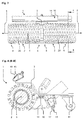
- FIG. 1 is a schematic side view of a cleaning device 1 according to the invention and in Fig. 2 is the sectional view AA of in Fig. 1 shown cleaning device 1 shown.
- the cleaning device 1 has two juxtaposed cleaning rollers 2, which are arranged on a bearing device 3 in opposite directions 4 and 5 projecting about a common axis of rotation 6 rotatably mounted.
- the cleaning device 1 has two drive motors 7, which are each arranged within the cleaning rollers 2. By the drive motors 7, the cleaning rollers 2 can be driven and rotate about the common axis of rotation 6.
- the drive motors 7 are controlled separately, so that the cleaning rollers 2 may have a different rotational speed from each other to facilitate a directional guidance of the cleaning device 1 and to allow in a simple manner without a considerable expenditure of force.
- the cleaning rollers 2 are mounted according to the invention at mutually facing ends 8 on the storage device 3.
- the mutually facing ends 8 opposite ends 9 of the cleaning rollers 2 thus remain free.
- free end faces of the cleaning rollers 2 at the outwardly directed ends 9, a surface 10 to be cleaned can be cleaned effectively along edges and in corners.
- the cleaning device 1 has a pivotable support wheel 11.
- Abstützrad 11 the weight of the cleaning device 1 between the cleaning rollers 2 and the support wheel 11 distributed.
- the cleaning device 1 also has a coarse dirt container 12, in which by the rotation of the cleaning rollers 2 from the surface to be cleaned 10 detached coarse dirt particles 13 can be collected.
- the coarse dirt container 12 has a container fixing arrangement 14, which removably fixes the coarse dirt container 12 to the cleaning appliance 1.
- the coarse dirt container 12 can be released at any time by the cleaning device 1 and emptied in a simple manner.
- the cleaning device 1 In order to be able to moisten the surface 10 to be cleaned with a cleaning agent, the cleaning device 1 according to the invention has a cleaning agent device 15 with a cleaning agent spray nozzle 16 and with a cleaning agent suction nozzle 17.
- a cleaning agent device 15 with a cleaning agent spray nozzle 16 and with a cleaning agent suction nozzle 17.
- the cleaning means 15 By the cleaning means 15, a particularly intensive cleaning of the surface to be cleaned 10 can be made and also fine or strongly adhering dirt particles 13 are removed from the surface 10 to be cleaned.
- the cleaning agent is sprayed onto the surface 10 to be cleaned or directly to the cleaning rollers 2 and then the excess cleaning agent by the enters, the enters, the crevice 17 of the cleaned Surface 10 sucked off.
- the entersstoffabsaugdüse 17 is arranged according to the invention near the surface to be cleaned 10 to allow the most effective extraction of detergent and to accelerate drying of the surface 10 to be cleaned when using a liquid detergent.
- the cleaning agent direction 15 has a wiper lip 18.
- the wiper lip 18 is made according to the invention of a flexible plastic material and can effectively wipe the water even at the uneven surface 10 to be cleaned.
- the Wasserabsaugdüse 17 is disposed on the wiper lip 18 to remove the water more effectively from the surface 10 to be cleaned.
- the cleaning device 1 also has a roller fixing arrangement 19, with which the cleaning rollers 2 are non-positively and / or positively releasably fixed to the cleaning device 1.
- the roller fixing arrangement 19 can have a magnetic, clamping, latching fastening unit or the like in order to enable a releasable fixing of the cleaning rollers 2 to the cleaning device 1.
- Fig. 3 shows a front view
- Fig. 4 shows the sectional view BB of in Fig. 3
- the cleaning device 1 has two cleaning rollers 2, which are designed in the form of brushes 20.
- the cleaning rollers 2 can also be foam or fabric rolls, so that depending on the surface to be cleaned 10 and the appropriate cleaning rollers 2 can be used.
- FIG. 5 is a schematic view of the cleaning device 1 according to the invention shown.
- the cleaning device 1 has a guide unit 21, through which the cleaning device 1 can be guided on the surface 10 to be cleaned by a user.
- a control device 22 connected to the drive motors 7 is arranged, by means of which the drive motors 7 are controlled and the rotational speed can be predetermined to the cleaning rollers 2, depending on the desired guide direction.
- the control device 22 is configured in the form of a control panel 23 with a push-button in order to design a directional guidance and a control of the cleaning device 1 for the user in a particularly simple manner.
- a storage tank 24 and a dirt tank 25 are arranged, which are interconnected by a cleaning unit 26.
- the cleaning unit 26 cleans the soiled cleaning agent from the dirty tank 25 and transfers the cleaned cleaning agent back into the storage tank 24.
- Such a configuration of the cleaning agent device 15 can reduce the consumption of cleaning agent and larger surfaces can be cleaned without adding detergent.
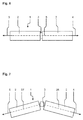
- FIG. 6 and in Fig. 7 are shown plan view of possible arrangement of the cleaning rollers 2 on the storage device 3.
- the cleaning rollers 2 are arranged side by side on the common axis of rotation 6 and according to the invention rotatably mounted on the bearing means 3.
- the cleaning rollers 2 are arranged on two axes of rotation 27 and 28 and also rotatably mounted on the bearing means 3. Due to the inventive arrangement of the cleaning rollers 2 on the two different axes of rotation 27 and 28, the directional guidance of the cleaning device 1 according to the invention can be additionally influenced and specified.
Landscapes
- Cleaning In General (AREA)
Applications Claiming Priority (1)
| Application Number | Priority Date | Filing Date | Title |
|---|---|---|---|
| DE102015103500.6A DE102015103500A1 (de) | 2015-03-10 | 2015-03-10 | Reinigungsgerät |
Publications (2)
| Publication Number | Publication Date |
|---|---|
| EP3066971A1 true EP3066971A1 (fr) | 2016-09-14 |
| EP3066971B1 EP3066971B1 (fr) | 2018-03-07 |
Family
ID=55524254
Family Applications (1)
| Application Number | Title | Priority Date | Filing Date |
|---|---|---|---|
| EP16159733.1A Not-in-force EP3066971B1 (fr) | 2015-03-10 | 2016-03-10 | Appareil de nettoyage |
Country Status (2)
| Country | Link |
|---|---|
| EP (1) | EP3066971B1 (fr) |
| DE (1) | DE102015103500A1 (fr) |
Cited By (7)
| Publication number | Priority date | Publication date | Assignee | Title |
|---|---|---|---|---|
| CN108937750A (zh) * | 2018-07-17 | 2018-12-07 | 中山市金舜家庭用品有限公司 | 一种表面清洁机 |
| CN109259675A (zh) * | 2018-11-12 | 2019-01-25 | 中山市金舜家庭用品有限公司 | 一种洗地机 |
| EP3569128A3 (fr) * | 2018-05-14 | 2019-12-11 | i-mop GmbH | Dispositif de nettoyage humide destiné au nettoyage humide d'une surface de plancher |
| CN114305253A (zh) * | 2021-12-30 | 2022-04-12 | 广东博智林机器人有限公司 | 清洁装置以及清洁设备 |
| CN114652216A (zh) * | 2020-12-24 | 2022-06-24 | 石家庄清流科技有限公司 | 一种双清洁辊扫拖一体设备及冲洗基座 |
| US11484174B2 (en) | 2018-09-21 | 2022-11-01 | Techtronic Floor Care Technology Limited | Cleaning tool for an extractor |
| US20240306869A1 (en) * | 2021-02-26 | 2024-09-19 | Dyson Technology Limited | Cleaner head |
Families Citing this family (3)
| Publication number | Priority date | Publication date | Assignee | Title |
|---|---|---|---|---|
| CN108378790B (zh) * | 2018-03-02 | 2021-03-12 | 漯河市第一人民医院 | 一种护理用清理装置的调节方法 |
| DE102018113574A1 (de) | 2018-06-07 | 2019-12-12 | Alfred Kärcher SE & Co. KG | Handgeführte Flächen-Reinigungsmaschine mit Sensoreinrichtung und Verfahren zum Betreiben einer handgeführten Flächen-Reinigungsmaschine |
| CN114468851B (zh) * | 2020-11-04 | 2024-03-19 | 添可智能科技有限公司 | 清洗机 |
Citations (3)
| Publication number | Priority date | Publication date | Assignee | Title |
|---|---|---|---|---|
| US4094032A (en) * | 1975-01-24 | 1978-06-13 | Leifheit International Gunter Leifheit Gmbh | Cleaning device |
| US8726441B1 (en) * | 2009-09-28 | 2014-05-20 | Bissell Homecare, Inc. | Floor sweeper with split brush assembly |
| CN105212841A (zh) * | 2014-06-06 | 2016-01-06 | 苏州科沃斯商用机器人有限公司 | 清洁设备 |
Family Cites Families (5)
| Publication number | Priority date | Publication date | Assignee | Title |
|---|---|---|---|---|
| GB287914A (en) * | 1927-03-29 | 1929-05-23 | Andrea Giambertoni | Improvements in or relating to electrically driven floor brushes |
| CH151622A (de) * | 1931-07-22 | 1931-12-31 | Mueller Gustav | Apparat zum Aufreiben und Blochen von Böden, sowie zum Staubsaugen. |
| US2508452A (en) * | 1945-05-10 | 1950-05-23 | George F Dwyer | Floor-sanding apparatus |
| DE102012002894A1 (de) * | 2012-02-14 | 2013-08-14 | Anton Jäger | Reinigungsvorrichtung |
| DE102013215198A1 (de) * | 2013-08-02 | 2015-02-05 | I-Mop Gmbh | Handgeführtes Bodenbearbeitungsgerät |
-
2015
- 2015-03-10 DE DE102015103500.6A patent/DE102015103500A1/de not_active Withdrawn
-
2016
- 2016-03-10 EP EP16159733.1A patent/EP3066971B1/fr not_active Not-in-force
Patent Citations (3)
| Publication number | Priority date | Publication date | Assignee | Title |
|---|---|---|---|---|
| US4094032A (en) * | 1975-01-24 | 1978-06-13 | Leifheit International Gunter Leifheit Gmbh | Cleaning device |
| US8726441B1 (en) * | 2009-09-28 | 2014-05-20 | Bissell Homecare, Inc. | Floor sweeper with split brush assembly |
| CN105212841A (zh) * | 2014-06-06 | 2016-01-06 | 苏州科沃斯商用机器人有限公司 | 清洁设备 |
Cited By (8)
| Publication number | Priority date | Publication date | Assignee | Title |
|---|---|---|---|---|
| EP3569128A3 (fr) * | 2018-05-14 | 2019-12-11 | i-mop GmbH | Dispositif de nettoyage humide destiné au nettoyage humide d'une surface de plancher |
| US11297993B2 (en) | 2018-05-14 | 2022-04-12 | I-Mop Gmbh | Wet-cleaning apparatus for the wet cleaning of a floor surface |
| CN108937750A (zh) * | 2018-07-17 | 2018-12-07 | 中山市金舜家庭用品有限公司 | 一种表面清洁机 |
| US11484174B2 (en) | 2018-09-21 | 2022-11-01 | Techtronic Floor Care Technology Limited | Cleaning tool for an extractor |
| CN109259675A (zh) * | 2018-11-12 | 2019-01-25 | 中山市金舜家庭用品有限公司 | 一种洗地机 |
| CN114652216A (zh) * | 2020-12-24 | 2022-06-24 | 石家庄清流科技有限公司 | 一种双清洁辊扫拖一体设备及冲洗基座 |
| US20240306869A1 (en) * | 2021-02-26 | 2024-09-19 | Dyson Technology Limited | Cleaner head |
| CN114305253A (zh) * | 2021-12-30 | 2022-04-12 | 广东博智林机器人有限公司 | 清洁装置以及清洁设备 |
Also Published As
| Publication number | Publication date |
|---|---|
| EP3066971B1 (fr) | 2018-03-07 |
| DE102015103500A1 (de) | 2016-09-15 |
Similar Documents
| Publication | Publication Date | Title |
|---|---|---|
| EP3066971B1 (fr) | Appareil de nettoyage | |
| DE102022102918A1 (de) | Bodenreinigungsgerät mit Kassette | |
| EP3206548B1 (fr) | Machine de nettoyage de surfaces et procédé permettant de faire fonctionner une machine de nettoyage de surfaces | |
| EP3426122B1 (fr) | Machine de nettoyage de surfaces | |
| EP3426124B1 (fr) | Nouveau dispositif de nettoyage et procédé de nettoyage | |
| EP2012642A2 (fr) | Dispositif de nettoyage des surfaces de sol | |
| EP3426121A1 (fr) | Machine de nettoyage de surfaces | |
| DE102022102924A1 (de) | Bodenreinigungsgerät mit beweglichem Abstreifelement | |
| EP2521477B1 (fr) | Appareil de nettoyage des sols | |
| DE202022101313U1 (de) | Bodenreinigungsgerät mit beweglichem Abstreifelement | |
| EP2832277A2 (fr) | Appareil portatif de traitement des sols | |
| EP4201284A1 (fr) | Machine de nettoyage de sol dotée d'une languette de préhension et procédé de retrait d'un dispositif de réservoir de fluide sale à partir d'une tête de nettoyage | |
| EP2278907B1 (fr) | Balayeuse mobile | |
| DE202022101312U1 (de) | Bodenreinigungsgerät mit Kassette | |
| WO2023151833A1 (fr) | Dispositif de nettoyage de plancher avec dispositif de balayage et procédé de fonctionnement d'un dispositif de nettoyage de plancher | |
| DE102023136194A1 (de) | Flächenbehandlungssystem | |
| AT409333B (de) | Mobile textilbelags-reinigungsmaschine | |
| EP4201285A1 (fr) | Machine de nettoyage de sol dotée d'une articulation pivotante et procédé de fonctionnement d'une machine de nettoyage de sol | |
| DE102022133009A1 (de) | Bodenreinigungsgerät mit Drehlagereinrichtung mit Widerlager | |
| DE69202868T2 (de) | Fussbodenreinigungsmaschine zum mehrfachen Gebrauch. | |
| DE19835185A1 (de) | Vorrichtung zum Behandeln von Oberflächen | |
| DE29513474U1 (de) | Applikationsorgan eines Dampfreinigungsgerätes | |
| DE102022133004A1 (de) | Bodenreinigungsgerät mit Bodenkopf mit Wandung | |
| EP4201283A1 (fr) | Machine de nettoyage du sol dotée d'au moins un élément de support | |
| EP4452034A1 (fr) | Machine de nettoyage de surface dotée d'un élément racleur incurvé |
Legal Events
| Date | Code | Title | Description |
|---|---|---|---|
| PUAI | Public reference made under article 153(3) epc to a published international application that has entered the european phase |
Free format text: ORIGINAL CODE: 0009012 |
|
| AK | Designated contracting states |
Kind code of ref document: A1 Designated state(s): AL AT BE BG CH CY CZ DE DK EE ES FI FR GB GR HR HU IE IS IT LI LT LU LV MC MK MT NL NO PL PT RO RS SE SI SK SM TR |
|
| AX | Request for extension of the european patent |
Extension state: BA ME |
|
| RIN1 | Information on inventor provided before grant (corrected) |
Inventor name: AREND, JENS Inventor name: GOTTWALD, MARCUS Inventor name: SCHNUR, JENS |
|
| RIN1 | Information on inventor provided before grant (corrected) |
Inventor name: AREND, JENS Inventor name: GOTTWALD, MARCUS Inventor name: SCHNUR, JENS |
|
| 17P | Request for examination filed |
Effective date: 20170313 |
|
| RBV | Designated contracting states (corrected) |
Designated state(s): AL AT BE BG CH CY CZ DE DK EE ES FI FR GB GR HR HU IE IS IT LI LT LU LV MC MK MT NL NO PL PT RO RS SE SI SK SM TR |
|
| REG | Reference to a national code |
Ref country code: DE Ref legal event code: R079 Ref document number: 502016000622 Country of ref document: DE Free format text: PREVIOUS MAIN CLASS: A47L0011180000 Ipc: A47L0011400000 |
|
| RIC1 | Information provided on ipc code assigned before grant |
Ipc: A47L 11/40 20060101AFI20170728BHEP Ipc: A47L 11/20 20060101ALI20170728BHEP Ipc: A47L 11/18 20060101ALI20170728BHEP |
|
| GRAP | Despatch of communication of intention to grant a patent |
Free format text: ORIGINAL CODE: EPIDOSNIGR1 |
|
| INTG | Intention to grant announced |
Effective date: 20170920 |
|
| GRAS | Grant fee paid |
Free format text: ORIGINAL CODE: EPIDOSNIGR3 |
|
| GRAA | (expected) grant |
Free format text: ORIGINAL CODE: 0009210 |
|
| AK | Designated contracting states |
Kind code of ref document: B1 Designated state(s): AL AT BE BG CH CY CZ DE DK EE ES FI FR GB GR HR HU IE IS IT LI LT LU LV MC MK MT NL NO PL PT RO RS SE SI SK SM TR |
|
| REG | Reference to a national code |
Ref country code: GB Ref legal event code: FG4D Free format text: NOT ENGLISH |
|
| REG | Reference to a national code |
Ref country code: CH Ref legal event code: EP Ref country code: AT Ref legal event code: REF Ref document number: 975619 Country of ref document: AT Kind code of ref document: T Effective date: 20180315 |
|
| REG | Reference to a national code |
Ref country code: IE Ref legal event code: FG4D Free format text: LANGUAGE OF EP DOCUMENT: GERMAN |
|
| REG | Reference to a national code |
Ref country code: DE Ref legal event code: R096 Ref document number: 502016000622 Country of ref document: DE |
|
| REG | Reference to a national code |
Ref country code: FR Ref legal event code: PLFP Year of fee payment: 3 |
|
| REG | Reference to a national code |
Ref country code: NL Ref legal event code: MP Effective date: 20180307 |
|
| REG | Reference to a national code |
Ref country code: LT Ref legal event code: MG4D |
|
| PG25 | Lapsed in a contracting state [announced via postgrant information from national office to epo] |
Ref country code: HR Free format text: LAPSE BECAUSE OF FAILURE TO SUBMIT A TRANSLATION OF THE DESCRIPTION OR TO PAY THE FEE WITHIN THE PRESCRIBED TIME-LIMIT Effective date: 20180307 Ref country code: LT Free format text: LAPSE BECAUSE OF FAILURE TO SUBMIT A TRANSLATION OF THE DESCRIPTION OR TO PAY THE FEE WITHIN THE PRESCRIBED TIME-LIMIT Effective date: 20180307 Ref country code: CY Free format text: LAPSE BECAUSE OF FAILURE TO SUBMIT A TRANSLATION OF THE DESCRIPTION OR TO PAY THE FEE WITHIN THE PRESCRIBED TIME-LIMIT Effective date: 20180307 Ref country code: NO Free format text: LAPSE BECAUSE OF FAILURE TO SUBMIT A TRANSLATION OF THE DESCRIPTION OR TO PAY THE FEE WITHIN THE PRESCRIBED TIME-LIMIT Effective date: 20180607 Ref country code: FI Free format text: LAPSE BECAUSE OF FAILURE TO SUBMIT A TRANSLATION OF THE DESCRIPTION OR TO PAY THE FEE WITHIN THE PRESCRIBED TIME-LIMIT Effective date: 20180307 Ref country code: ES Free format text: LAPSE BECAUSE OF FAILURE TO SUBMIT A TRANSLATION OF THE DESCRIPTION OR TO PAY THE FEE WITHIN THE PRESCRIBED TIME-LIMIT Effective date: 20180307 |
|
| PGFP | Annual fee paid to national office [announced via postgrant information from national office to epo] |
Ref country code: DE Payment date: 20180601 Year of fee payment: 3 |
|
| PG25 | Lapsed in a contracting state [announced via postgrant information from national office to epo] |
Ref country code: LV Free format text: LAPSE BECAUSE OF FAILURE TO SUBMIT A TRANSLATION OF THE DESCRIPTION OR TO PAY THE FEE WITHIN THE PRESCRIBED TIME-LIMIT Effective date: 20180307 Ref country code: SE Free format text: LAPSE BECAUSE OF FAILURE TO SUBMIT A TRANSLATION OF THE DESCRIPTION OR TO PAY THE FEE WITHIN THE PRESCRIBED TIME-LIMIT Effective date: 20180307 Ref country code: BG Free format text: LAPSE BECAUSE OF FAILURE TO SUBMIT A TRANSLATION OF THE DESCRIPTION OR TO PAY THE FEE WITHIN THE PRESCRIBED TIME-LIMIT Effective date: 20180607 Ref country code: RS Free format text: LAPSE BECAUSE OF FAILURE TO SUBMIT A TRANSLATION OF THE DESCRIPTION OR TO PAY THE FEE WITHIN THE PRESCRIBED TIME-LIMIT Effective date: 20180307 Ref country code: GR Free format text: LAPSE BECAUSE OF FAILURE TO SUBMIT A TRANSLATION OF THE DESCRIPTION OR TO PAY THE FEE WITHIN THE PRESCRIBED TIME-LIMIT Effective date: 20180608 |
|
| PGFP | Annual fee paid to national office [announced via postgrant information from national office to epo] |
Ref country code: FR Payment date: 20180625 Year of fee payment: 3 |
|
| PG25 | Lapsed in a contracting state [announced via postgrant information from national office to epo] |
Ref country code: MT Free format text: LAPSE BECAUSE OF FAILURE TO SUBMIT A TRANSLATION OF THE DESCRIPTION OR TO PAY THE FEE WITHIN THE PRESCRIBED TIME-LIMIT Effective date: 20180307 |
|
| PG25 | Lapsed in a contracting state [announced via postgrant information from national office to epo] |
Ref country code: AL Free format text: LAPSE BECAUSE OF FAILURE TO SUBMIT A TRANSLATION OF THE DESCRIPTION OR TO PAY THE FEE WITHIN THE PRESCRIBED TIME-LIMIT Effective date: 20180307 Ref country code: NL Free format text: LAPSE BECAUSE OF FAILURE TO SUBMIT A TRANSLATION OF THE DESCRIPTION OR TO PAY THE FEE WITHIN THE PRESCRIBED TIME-LIMIT Effective date: 20180307 Ref country code: IT Free format text: LAPSE BECAUSE OF FAILURE TO SUBMIT A TRANSLATION OF THE DESCRIPTION OR TO PAY THE FEE WITHIN THE PRESCRIBED TIME-LIMIT Effective date: 20180307 Ref country code: EE Free format text: LAPSE BECAUSE OF FAILURE TO SUBMIT A TRANSLATION OF THE DESCRIPTION OR TO PAY THE FEE WITHIN THE PRESCRIBED TIME-LIMIT Effective date: 20180307 Ref country code: RO Free format text: LAPSE BECAUSE OF FAILURE TO SUBMIT A TRANSLATION OF THE DESCRIPTION OR TO PAY THE FEE WITHIN THE PRESCRIBED TIME-LIMIT Effective date: 20180307 Ref country code: PL Free format text: LAPSE BECAUSE OF FAILURE TO SUBMIT A TRANSLATION OF THE DESCRIPTION OR TO PAY THE FEE WITHIN THE PRESCRIBED TIME-LIMIT Effective date: 20180307 |
|
| PG25 | Lapsed in a contracting state [announced via postgrant information from national office to epo] |
Ref country code: SM Free format text: LAPSE BECAUSE OF FAILURE TO SUBMIT A TRANSLATION OF THE DESCRIPTION OR TO PAY THE FEE WITHIN THE PRESCRIBED TIME-LIMIT Effective date: 20180307 Ref country code: SK Free format text: LAPSE BECAUSE OF FAILURE TO SUBMIT A TRANSLATION OF THE DESCRIPTION OR TO PAY THE FEE WITHIN THE PRESCRIBED TIME-LIMIT Effective date: 20180307 Ref country code: CZ Free format text: LAPSE BECAUSE OF FAILURE TO SUBMIT A TRANSLATION OF THE DESCRIPTION OR TO PAY THE FEE WITHIN THE PRESCRIBED TIME-LIMIT Effective date: 20180307 |
|
| REG | Reference to a national code |
Ref country code: BE Ref legal event code: MM Effective date: 20180331 Ref country code: DE Ref legal event code: R097 Ref document number: 502016000622 Country of ref document: DE |
|
| REG | Reference to a national code |
Ref country code: IE Ref legal event code: MM4A |
|
| PG25 | Lapsed in a contracting state [announced via postgrant information from national office to epo] |
Ref country code: LU Free format text: LAPSE BECAUSE OF NON-PAYMENT OF DUE FEES Effective date: 20180310 Ref country code: PT Free format text: LAPSE BECAUSE OF FAILURE TO SUBMIT A TRANSLATION OF THE DESCRIPTION OR TO PAY THE FEE WITHIN THE PRESCRIBED TIME-LIMIT Effective date: 20180709 |
|
| PLBE | No opposition filed within time limit |
Free format text: ORIGINAL CODE: 0009261 |
|
| STAA | Information on the status of an ep patent application or granted ep patent |
Free format text: STATUS: NO OPPOSITION FILED WITHIN TIME LIMIT |
|
| PG25 | Lapsed in a contracting state [announced via postgrant information from national office to epo] |
Ref country code: MC Free format text: LAPSE BECAUSE OF FAILURE TO SUBMIT A TRANSLATION OF THE DESCRIPTION OR TO PAY THE FEE WITHIN THE PRESCRIBED TIME-LIMIT Effective date: 20180307 Ref country code: IE Free format text: LAPSE BECAUSE OF NON-PAYMENT OF DUE FEES Effective date: 20180310 Ref country code: DK Free format text: LAPSE BECAUSE OF FAILURE TO SUBMIT A TRANSLATION OF THE DESCRIPTION OR TO PAY THE FEE WITHIN THE PRESCRIBED TIME-LIMIT Effective date: 20180307 |
|
| 26N | No opposition filed |
Effective date: 20181210 |
|
| PG25 | Lapsed in a contracting state [announced via postgrant information from national office to epo] |
Ref country code: SI Free format text: LAPSE BECAUSE OF FAILURE TO SUBMIT A TRANSLATION OF THE DESCRIPTION OR TO PAY THE FEE WITHIN THE PRESCRIBED TIME-LIMIT Effective date: 20180307 Ref country code: BE Free format text: LAPSE BECAUSE OF NON-PAYMENT OF DUE FEES Effective date: 20180331 |
|
| REG | Reference to a national code |
Ref country code: DE Ref legal event code: R119 Ref document number: 502016000622 Country of ref document: DE |
|
| REG | Reference to a national code |
Ref country code: CH Ref legal event code: PL |
|
| PG25 | Lapsed in a contracting state [announced via postgrant information from national office to epo] |
Ref country code: DE Free format text: LAPSE BECAUSE OF NON-PAYMENT OF DUE FEES Effective date: 20191001 Ref country code: CH Free format text: LAPSE BECAUSE OF NON-PAYMENT OF DUE FEES Effective date: 20190331 Ref country code: LI Free format text: LAPSE BECAUSE OF NON-PAYMENT OF DUE FEES Effective date: 20190331 |
|
| PG25 | Lapsed in a contracting state [announced via postgrant information from national office to epo] |
Ref country code: FR Free format text: LAPSE BECAUSE OF NON-PAYMENT OF DUE FEES Effective date: 20190331 |
|
| PG25 | Lapsed in a contracting state [announced via postgrant information from national office to epo] |
Ref country code: TR Free format text: LAPSE BECAUSE OF FAILURE TO SUBMIT A TRANSLATION OF THE DESCRIPTION OR TO PAY THE FEE WITHIN THE PRESCRIBED TIME-LIMIT Effective date: 20180307 |
|
| PG25 | Lapsed in a contracting state [announced via postgrant information from national office to epo] |
Ref country code: MK Free format text: LAPSE BECAUSE OF NON-PAYMENT OF DUE FEES Effective date: 20180307 Ref country code: HU Free format text: LAPSE BECAUSE OF FAILURE TO SUBMIT A TRANSLATION OF THE DESCRIPTION OR TO PAY THE FEE WITHIN THE PRESCRIBED TIME-LIMIT; INVALID AB INITIO Effective date: 20160310 |
|
| PG25 | Lapsed in a contracting state [announced via postgrant information from national office to epo] |
Ref country code: IS Free format text: LAPSE BECAUSE OF FAILURE TO SUBMIT A TRANSLATION OF THE DESCRIPTION OR TO PAY THE FEE WITHIN THE PRESCRIBED TIME-LIMIT Effective date: 20180707 |
|
| GBPC | Gb: european patent ceased through non-payment of renewal fee |
Effective date: 20200310 |
|
| PG25 | Lapsed in a contracting state [announced via postgrant information from national office to epo] |
Ref country code: GB Free format text: LAPSE BECAUSE OF NON-PAYMENT OF DUE FEES Effective date: 20200310 |
|
| REG | Reference to a national code |
Ref country code: AT Ref legal event code: MM01 Ref document number: 975619 Country of ref document: AT Kind code of ref document: T Effective date: 20210310 |
|
| PG25 | Lapsed in a contracting state [announced via postgrant information from national office to epo] |
Ref country code: AT Free format text: LAPSE BECAUSE OF NON-PAYMENT OF DUE FEES Effective date: 20210310 |