EP3075422B2 - Fixation de randonnée avec deux cales de montée articulées sur le même axe situé sur la butée arrière - Google Patents
Fixation de randonnée avec deux cales de montée articulées sur le même axe situé sur la butée arrière Download PDFInfo
- Publication number
- EP3075422B2 EP3075422B2 EP16160420.2A EP16160420A EP3075422B2 EP 3075422 B2 EP3075422 B2 EP 3075422B2 EP 16160420 A EP16160420 A EP 16160420A EP 3075422 B2 EP3075422 B2 EP 3075422B2
- Authority
- EP
- European Patent Office
- Prior art keywords
- ski
- heel
- featuring
- downhill
- pedal
- Prior art date
- Legal status (The legal status is an assumption and is not a legal conclusion. Google has not performed a legal analysis and makes no representation as to the accuracy of the status listed.)
- Active
Links
Images
Classifications
-
- A—HUMAN NECESSITIES
- A63—SPORTS; GAMES; AMUSEMENTS
- A63C—SKATES; SKIS; ROLLER SKATES; DESIGN OR LAYOUT OF COURTS, RINKS OR THE LIKE
- A63C7/00—Devices preventing skis from slipping back; Ski-stoppers or ski-brakes
- A63C7/10—Hinged stoppage blades attachable to the skis in such manner that these blades can be moved out of the operative position
- A63C7/1006—Ski-stoppers
- A63C7/1013—Ski-stoppers actuated by the boot
- A63C7/102—Ski-stoppers actuated by the boot articulated about one transverse axis
-
- A—HUMAN NECESSITIES
- A63—SPORTS; GAMES; AMUSEMENTS
- A63C—SKATES; SKIS; ROLLER SKATES; DESIGN OR LAYOUT OF COURTS, RINKS OR THE LIKE
- A63C7/00—Devices preventing skis from slipping back; Ski-stoppers or ski-brakes
- A63C7/10—Hinged stoppage blades attachable to the skis in such manner that these blades can be moved out of the operative position
- A63C7/1006—Ski-stoppers
- A63C7/1013—Ski-stoppers actuated by the boot
- A63C7/102—Ski-stoppers actuated by the boot articulated about one transverse axis
- A63C7/1026—Ski-stoppers actuated by the boot articulated about one transverse axis laterally retractable above the ski surface
-
- A—HUMAN NECESSITIES
- A63—SPORTS; GAMES; AMUSEMENTS
- A63C—SKATES; SKIS; ROLLER SKATES; DESIGN OR LAYOUT OF COURTS, RINKS OR THE LIKE
- A63C7/00—Devices preventing skis from slipping back; Ski-stoppers or ski-brakes
- A63C7/10—Hinged stoppage blades attachable to the skis in such manner that these blades can be moved out of the operative position
- A63C7/1006—Ski-stoppers
- A63C7/1013—Ski-stoppers actuated by the boot
- A63C7/1033—Ski-stoppers actuated by the boot articulated about at least two transverse axes
-
- A—HUMAN NECESSITIES
- A63—SPORTS; GAMES; AMUSEMENTS
- A63C—SKATES; SKIS; ROLLER SKATES; DESIGN OR LAYOUT OF COURTS, RINKS OR THE LIKE
- A63C7/00—Devices preventing skis from slipping back; Ski-stoppers or ski-brakes
- A63C7/10—Hinged stoppage blades attachable to the skis in such manner that these blades can be moved out of the operative position
- A63C7/1006—Ski-stoppers
- A63C7/1013—Ski-stoppers actuated by the boot
- A63C7/1033—Ski-stoppers actuated by the boot articulated about at least two transverse axes
- A63C7/104—Ski-stoppers actuated by the boot articulated about at least two transverse axes laterally retractable above the ski surface
-
- A—HUMAN NECESSITIES
- A63—SPORTS; GAMES; AMUSEMENTS
- A63C—SKATES; SKIS; ROLLER SKATES; DESIGN OR LAYOUT OF COURTS, RINKS OR THE LIKE
- A63C7/00—Devices preventing skis from slipping back; Ski-stoppers or ski-brakes
- A63C7/10—Hinged stoppage blades attachable to the skis in such manner that these blades can be moved out of the operative position
- A63C7/1006—Ski-stoppers
- A63C7/1046—Ski-stoppers actuated by the ski-binding
-
- A—HUMAN NECESSITIES
- A63—SPORTS; GAMES; AMUSEMENTS
- A63C—SKATES; SKIS; ROLLER SKATES; DESIGN OR LAYOUT OF COURTS, RINKS OR THE LIKE
- A63C7/00—Devices preventing skis from slipping back; Ski-stoppers or ski-brakes
- A63C7/10—Hinged stoppage blades attachable to the skis in such manner that these blades can be moved out of the operative position
- A63C7/1006—Ski-stoppers
- A63C7/1046—Ski-stoppers actuated by the ski-binding
- A63C7/1053—Ski-stoppers actuated by the ski-binding laterally retractable above the ski surface
-
- A—HUMAN NECESSITIES
- A63—SPORTS; GAMES; AMUSEMENTS
- A63C—SKATES; SKIS; ROLLER SKATES; DESIGN OR LAYOUT OF COURTS, RINKS OR THE LIKE
- A63C9/00—Ski bindings
- A63C9/006—Ski bindings with a climbing wedge
-
- A—HUMAN NECESSITIES
- A63—SPORTS; GAMES; AMUSEMENTS
- A63C—SKATES; SKIS; ROLLER SKATES; DESIGN OR LAYOUT OF COURTS, RINKS OR THE LIKE
- A63C9/00—Ski bindings
- A63C9/08—Ski bindings yieldable or self-releasing in the event of an accident, i.e. safety bindings
- A63C9/0807—Ski bindings yieldable or self-releasing in the event of an accident, i.e. safety bindings for both towing and downhill skiing
-
- A—HUMAN NECESSITIES
- A63—SPORTS; GAMES; AMUSEMENTS
- A63C—SKATES; SKIS; ROLLER SKATES; DESIGN OR LAYOUT OF COURTS, RINKS OR THE LIKE
- A63C9/00—Ski bindings
- A63C9/08—Ski bindings yieldable or self-releasing in the event of an accident, i.e. safety bindings
- A63C9/084—Ski bindings yieldable or self-releasing in the event of an accident, i.e. safety bindings with heel hold-downs, e.g. swingable
- A63C9/0841—Ski bindings yieldable or self-releasing in the event of an accident, i.e. safety bindings with heel hold-downs, e.g. swingable with a single jaw
- A63C9/0842—Ski bindings yieldable or self-releasing in the event of an accident, i.e. safety bindings with heel hold-downs, e.g. swingable with a single jaw the jaw pivoting on the body or base about a transverse axis
Definitions
- the invention relates to a heel holder for a ski binding such as a ski.
- the heel holder includes a base, a heel machine, a pedal and a ski brake.
- the pedal forms a first lock for the ski brake in a known manner.
- the heel holder also includes a second ski brake lock that locks the ski brake when the heel holder is not in a position suitable for skiing downhill.
- ski brakes with pedal control which are only moved into a position and held there when the binding is put on, in which the ski brake is arranged next to the ski and has no braking effect, are unsuitable.
- the heel holder pedal is no longer held down, which unlocks the brake. This is an unacceptable condition for touring, which is why ski lanyards are still used in combined downhill and touring bindings.
- lanyards are no longer accepted by athletes as a contemporary solution.
- the conventional pedal-operated ski brakes have the disadvantage that they protrude downwards from the ski before the athlete gets into the binding and after getting out of the binding, which means that the transport volume of the skis is larger than it would have to be with the ski brake locked.
- the patent specification FR 2 490 099 A1 shows a plate touring binding without ski stoppers and the EP 0 054 928 A1 shows a ski stopper for touring bindings with plates. It is therefore an object of the invention to provide a heel holder with a ski brake that triggers reliably, that is to say, develops its braking effect if the heel holder is triggered when skiing, for example due to a fall, but at the same time held in a locked position when the ski is not in use or used as a touring ski.
- the invention relates to a heel holder for a ski, in particular for a ski, which has a base, a heel automatic, a ski brake, a pedal that can be moved from a first position to a second position, and in the first position releases the ski brake for braking and in a second position holds the ski brake next to the ski in a position in which the ski brake cannot brake the ski.
- the heel holder also has a ski brake lock, with which the ski brake can be locked when the pedal is in the second position.
- the ski brake has, in addition to the known first mechanical locking, which is caused by the athlete getting into the binding and using his weight to push the pedal from its first position above the ski surface down towards the ski surface into a second position , a second mechanical lock.
- the second lock holds the ski brake in the locked position, that is, in a position in which it lies next to the ski and does not protrude downward over the ski before the athlete gets on the ski, for example during transport or storage .
- the second lock also keeps the ski brake in the locked position in touring mode.
- Touring mode here means the setting of the ski connection that is selected for touring, that is, the heel of the shoe is released from the heel holder and can move out of the heel holder when walking.
- the downhill mode is the setting of the binding in which the shoe is held firmly in the heel holder.
- the ski brake is connected to the pedal via a mechanism that biases the ski brake into the braking position. This means that when the pedal is unloaded, the brake is always in the braking position when the pedal is the only lock for the brake. The weight of the athlete pushes the pedal towards the surface of the ski when getting into the binding and the brake is swiveled up next to the ski via a swivel connection and held there as long as the pedal is loaded. If the pedal is suddenly released, for example when the binding is released in the event of a fall, the brake is triggered and slows down the ski.
- the second lock for the ski brake has a locking element that is connected to the pedal and a counter-locking element that is movably mounted in the base.
- the locking element is preferably connected to the pedal on its underside and, when the pedal is in the release position for the ski brake, projects downwards towards the ski surface from the underside of the pedal.
- the counter-locking element is biased by means of a spring element in the direction of the pedal, that is, in the direction of the locking element on the pedal, so that preferably one end of the counter-locking element is in a locking engagement with the locking element when the spring element is tensioned.
- This locking engagement can, for example, consist of the end of the counter-locking element overlapping an end of the locking element, with the counter-locking element lying above the locking element or a part of the locking element in the overlap area, so that the unloaded pedal cannot be moved from its second position to the first position.
- the counter-locking element can engage in the locking element in order to produce the locking engagement or press the locking element into a locking position against a spring force, in which case the spring force is used to unlock the locking element is smaller than the spring force for tensioning the counter-locking element.
- the counter-locking element can extend in the base in a longitudinal direction of the base or the ski, from the locking element to under the heel holder, and in an area below the heel holder has a projection projecting vertically upwards in the direction of the heel holder.
- the projection has an engagement surface at its free end facing away from the counter-locking element, which can interact with a pin connected to the heel automatic with a counter-action surface.
- the attack surface and the counter-attack surface can in particular be inclined surfaces which are designed in such a way that a movement of the automatic heel essentially perpendicular to the ski surface causes a movement of the counter-locking element in a direction opposite to the direction of skiing.
- the pin When entering the heel holder and the resulting pivoting of the heel machine into the position in which a sole holder of the heel machine rests on the surface of the sole of the athlete's shoe, the pin can come into effective engagement with the projection, whereby the counter-locking element against the force of the Spring element can be moved away from the locking element against the direction of travel of the ski.
- the heel machine may have a tensioning device with the sole holder and a connecting structure, the connecting structure connecting the tensioning device to the base.
- the clamping device can be connected to the connecting structure so that it can pivot about a first axis
- the connecting structure can be connected to the base so that it can pivot about a second axis.
- the pin is preferably formed on the connecting structure.
- the heel holder is preferably the heel of a touring binding or a combined downhill and touring binding, with the ski brake being secured by the second lock in touring mode.
- the heel holder can have a first and an additional second climbing aid, the first climbing aid supporting the athlete's shoe at a first climbing angle and the second climbing aid supporting the shoe at a second climbing angle, the second climbing angle being greater than the first climbing angle.
- the ski brake is in particular a separate part that is not connected to the heel holder, but can be pushed independently of the heel holder, for example onto a rail that is connected to the surface of the ski.
- Another aspect concerns a ski with a combined downhill and touring binding with a toe holder, a heel holder and a ski brake.
- the heel holder is preferably the heel holder described above, with which the ski brake can be held in a non-braking position in touring mode.
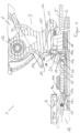
- the Figure 1 shows a heel holder 1 with a base 2, a heel machine 3, a pedal 4 and a ski brake 5.
- the heel machine 3 has a tensioning element 6 with a sole holder 7 and a connecting structure 10.
- the connecting structure 10 is connected to the base 2 in a first swivel joint 11 and to the clamping element 6 in a second swivel joint 12.
- the clamping element 6 can be in the swivel joint 12 relative to the base 2 and relative to the connecting structure 10 can be pivoted, the connecting structure 10 can be pivoted in the pivot joint 11 at least relative to the base 1.
- the base 2 has a carriage 24 which can be moved transversely to the longitudinal axis of the ski and enables additional transverse movements of the heel automatic 3 in extreme driving situations and a transverse release of the heel holder 1, for example in the event of a fall.
- a locking element 13 is connected to the underside 4a of the pedal 4, which in the exemplary embodiment has a rectangular profile which protrudes downwards from the underside 4a of the pedal 4 and forms a support surface 13a running parallel to the underside 4a.
- a counter-locking element 14 is guided in the base 2 or below the base 2 and is pressed at one end 14a by a spring element 15 with a spring force in the direction of travel of the ski 16.
- a support surface 14c is formed, which rests on the support surface 13a of the locking element 13, and thereby prevents the pedal 2 from moving from a second position shown, in which it rests on the surface of the ski 16 and the ski brake 5 in the shown position next to the ski, in which the ski brake 5 has no braking function, holds and locks.
- the counter-locking element 14 has an arm or projection 18 which projects vertically upward and which has a slope 18b at its upper end 18a.
- the counter-locking element 14 has a further projection 20 between the projection 18 and the end 14b, which can be guided in a groove in the base 2, for example, in order to support a straight guidance of the counter-locking element 14.
- the counter-locking element 14 can also be guided at least partially in a sleeve connected to, for example, the base 3 or guided in another known manner in order to prevent the counter-locking element 14 from bending or buckling.
- the projection 20 In the downhill position of the ski 16, the projection 20 is moved back against the direction of travel so far that its front end in the direction of travel comes to rest behind the edge 23 formed on the underside of the slide 24 guided in the base 2.
- the edge 23 can have an interruption in the middle, so that the counter-locking element 14 or the projection 20 can be moved freely in and against the direction of travel of the ski 16 when the carriage 24 lies in a permissible, non-triggering position in the base 2. If the carriage 24 leaves this position transversely to the direction of travel, the projection comes into an area of the edge 23 next to or outside the interruption and is thereby prevented by the edge 23 from being pushed back into the locking position by the spring 15, even if the pedal 4 is no longer pressed onto the ski surface by the ski boot.
- a nose or a pin 17 is formed, with an end 17a with a slope 17b.
- the ski brake 5 Since essentially at the same time the pedal 4 is depressed by the weight of the athlete getting into the binding, the ski brake 5 remains in the locked, non-braking position, with the locking now being established and held by the pedal 4.
- the locking element 13 and the counter-locking element 14 form a lock for the ski brake 5 when the pin 17 and the projection 18 do not interact with one another. This means that this locking can be active when the ski 16 is being transported or stored, or when the heel holder 1 or the heel automatic 3 is in a position in which the binding is used as a touring binding. If, on the other hand, the binding is used as a downhill binding, the locking element 13 and the counter-locking element 14 are no longer in locking engagement; the locking of the ski brake 5 in the position in which it does not brake the ski 16 is now ensured by the pedal 4 loaded with the skier .
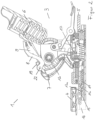
- the Figure 2 shows the heel holder 1 in the position for the downhill mode, in which both the connecting structure 10 and the tensioning element 6 of the heel automatic 3 are pivoted to the base 2.
- the pin 17 is completely retracted into the opening 21 of the base 2 and, via the interaction of the bevels 17b, 18b, has moved the counter-locking element 14 against the force of the spring element 15 against the direction of travel of the ski 16.
- the two support surfaces 13a, 14c no longer overlap, so that the ski brake 5 is no longer locked in the non-braking position by the interaction of the locking element 13 and the counter-locking element 14.
- This locking is now ensured by the pedal 4 in a known manner, since the athlete now holds the pedal 4 with his weight in the position shown on the top of the ski 16, in which the ski brake 5 is held in the non-braking position.
- the first climbing aid 8 and the second climbing aid 9 can also be seen, here in the position for downhill mode.
- the two climbing aids 8, 9 can be pivoted in a common joint 22 Heel automatics 3 or the tensioning element 6 are connected and have at least one common spring element 19, which secures the first climbing aid 8 and the second climbing aid 9 in at least the position shown against unwanted pivoting.
Landscapes
- Footwear And Its Accessory, Manufacturing Method And Apparatuses (AREA)
- Fittings On The Vehicle Exterior For Carrying Loads, And Devices For Holding Or Mounting Articles (AREA)
- Braking Arrangements (AREA)
Claims (11)
- Ski comprenant une fixation combinée de descente et de randonnée avec une butée avant et une talonnière, dans lequel(a) la talonnière (1) comporte une base (2), une unité talon automatique (3) et une pédale (4),(b) la talonnière (1) comporte une première aide à la montée et une seconde aide à la montée supplémentaire (8, 9),(c) la première aide à la montée (8) soutient la chaussure d'un sportif à un premier angle d'inclinaison et la seconde aide à la montée (9) soutient la chaussure à un second angle d'inclinaison, le second angle d'inclinaison étant supérieur au premier angle d'inclinaison,(d) les deux aides à la montée (8, 9) sont reliées à l'unité talon automatique (3) de manière à pouvoir pivoter par le biais d'une articulation commune (22),(e) la chaussure est fermement maintenue dans la talonnière (1) dans un mode de descente et le talon de la chaussure est libéré de la talonnière (1) dans un mode de randonnée, et la talonnière (1) comporte un frein de ski (5),(f) la pédale (4) peut être amenée d'une première position, dans laquelle le frein de ski (5) fait saillie à partir du ski (16) vers le bas et produit un effet de freinage, à une seconde position, dans laquelle le frein de ski (5) se situe à côté du ski (16) sans action de freinage,(g) et la talonnière (1) comporte un dispositif de blocage pour le frein de ski (5), au moyen duquel le frein de ski (5) peut être bloqué dans la seconde position, et le un dispositif de blocage maintient le frein de ski (5) dans le mode de randonnée dans une position bloquée,
caractérisé en ce que(h) le dispositif de blocage comporte un élément de blocage (13) relié à la pédale (4) et un élément de blocage complémentaire (14) monté de manière mobile dans la base (2), et en ce que(i) l'élément de blocage complémentaire (14) est préchargé au moyen d'un élément à ressort (15) vers l'élément de blocage (13). - Ski comprenant une fixation combinée de descente et de randonnée selon la revendication 1, dans lequel les aides à la montée (8, 9) comportent au moins un élément à ressort commun (19) qui empêche un pivotement non voulu de la première aide à la montée (8) et de la seconde aide à la montée (9) dans au moins une position pour le mode de descente.
- Ski comprenant une fixation combinée de descente et de randonnée selon au moins une des revendications précédentes, dans lequel l'unité talon automatique (3) comporte un dispositif de serrage (6) avec un élément de maintien de semelle (7) et une structure de liaison (10) qui relie le dispositif de serrage (6) à la base (2).
- Ski comprenant une fixation combinée de descente et de randonnée selon la revendication immédiatement précédente, dans lequel le dispositif de serrage (6) est relié à la structure de liaison (10) de manière à pouvoir pivoter autour d'un premier axe.
- Ski comprenant une fixation combinée de descente et de randonnée selon la revendication 3 ou la revendication 4, dans lequel la structure de liaison (10) est reliée à la base (2) de manière à pouvoir pivoter autour d'un second axe.
- Ski comprenant une fixation combinée de descente et de randonnée selon au moins une des revendications précédentes, dans lequel la base (2) comporte un coulisseau (24) qui est mobile transversalement à un axe longitudinal du ski et permet des mouvements transversaux supplémentaires de l'unité talon automatique (3) et un déclenchement transversal de la talonnière (1).
- Ski comprenant une fixation combinée de descente et de randonnée selon au moins une des revendications précédentes, dans lequel la talonnière (1) et le frein de ski (5) sont des composants séparés qui peuvent glisser, séparément l'un de l'autre, sur un rail relié à une surface du ski (16).
- Ski comprenant une fixation combinée de descente et de randonnée selon la revendication immédiatement précédente, dans lequel l'élément de blocage (13) est reliée à la face inférieure de la pédale (4) et fait saillie à partir de la face inférieure de la pédale (4) vers la surface du ski (16), et / ou dans lequel l'élément de blocage complémentaire (14) est préchargé au moyen d'un élément à ressort (15) dans un sens de déplacement du ski (16).
- Ski comprenant une fixation combinée de descente et de randonnée selon la revendication immédiatement précédente, dans lequel l'élément de blocage complémentaire (14) s'étend dans la base (2) en direction longitudinale du ski (16) à partir de l'élément de blocage (13) jusque sous l'unité talon automatique (3), et comporte une pièce en saillie (18) faisant saillie perpendiculairement vers le haut vers l'unité talon automatique (3) dans une zone située sous l'unité talon automatique (3).
- Ski comprenant une fixation combinée de descente et de randonnée selon la revendication immédiatement précédente, dans lequel la pièce en saillie (18) comporte, au niveau de son extrémité (18a) qui s'éloigne de l'élément de blocage complémentaire (14), une surface d'appui (18b) qui coopère avec une surface d'appui complémentaire (17b) par un tenon (17) relié à l'unité talon automatique (3).
- Ski comprenant une fixation combinée de descente et de randonnée selon l'une quelconque des deux revendications immédiatement précédentes, dans lequel le tenon (17) est formé sur la structure de liaison (10) et / ou le tenon (17) parvient en prise effective avec la pièce en saillie (18) lors de l'entrée de la chaussure d'un utilisateur dans la talonnière (1) et l'élément de liaison complémentaire (14) se déplace à l'encontre de la force de l'élément à ressort (15) dans le sens contraire du sens de déplacement du ski (16) en s'éloignant de l'élément de blocage (13).
Priority Applications (1)
| Application Number | Priority Date | Filing Date | Title |
|---|---|---|---|
| EP18204581.5A EP3473307B1 (fr) | 2012-08-07 | 2013-08-07 | Frein de ski à verrouillage |
Applications Claiming Priority (2)
| Application Number | Priority Date | Filing Date | Title |
|---|---|---|---|
| DE102012214001.8A DE102012214001B4 (de) | 2012-08-07 | 2012-08-07 | Skibremse mit Verriegelung |
| EP13179653.4A EP2695647B1 (fr) | 2012-08-07 | 2013-08-07 | Frein pour ski avec verrouillage |
Related Parent Applications (1)
| Application Number | Title | Priority Date | Filing Date |
|---|---|---|---|
| EP13179653.4A Division EP2695647B1 (fr) | 2012-08-07 | 2013-08-07 | Frein pour ski avec verrouillage |
Related Child Applications (2)
| Application Number | Title | Priority Date | Filing Date |
|---|---|---|---|
| EP18204581.5A Division EP3473307B1 (fr) | 2012-08-07 | 2013-08-07 | Frein de ski à verrouillage |
| EP18204581.5A Division-Into EP3473307B1 (fr) | 2012-08-07 | 2013-08-07 | Frein de ski à verrouillage |
Publications (3)
| Publication Number | Publication Date |
|---|---|
| EP3075422A1 EP3075422A1 (fr) | 2016-10-05 |
| EP3075422B1 EP3075422B1 (fr) | 2018-11-07 |
| EP3075422B2 true EP3075422B2 (fr) | 2023-10-18 |
Family
ID=48985572
Family Applications (3)
| Application Number | Title | Priority Date | Filing Date |
|---|---|---|---|
| EP18204581.5A Active EP3473307B1 (fr) | 2012-08-07 | 2013-08-07 | Frein de ski à verrouillage |
| EP13179653.4A Active EP2695647B1 (fr) | 2012-08-07 | 2013-08-07 | Frein pour ski avec verrouillage |
| EP16160420.2A Active EP3075422B2 (fr) | 2012-08-07 | 2013-08-07 | Fixation de randonnée avec deux cales de montée articulées sur le même axe situé sur la butée arrière |
Family Applications Before (2)
| Application Number | Title | Priority Date | Filing Date |
|---|---|---|---|
| EP18204581.5A Active EP3473307B1 (fr) | 2012-08-07 | 2013-08-07 | Frein de ski à verrouillage |
| EP13179653.4A Active EP2695647B1 (fr) | 2012-08-07 | 2013-08-07 | Frein pour ski avec verrouillage |
Country Status (2)
| Country | Link |
|---|---|
| EP (3) | EP3473307B1 (fr) |
| DE (2) | DE102012214001B4 (fr) |
Families Citing this family (8)
| Publication number | Priority date | Publication date | Assignee | Title |
|---|---|---|---|---|
| DE102012214001B4 (de) | 2012-08-07 | 2014-03-13 | Marker Deutschland Gmbh | Skibremse mit Verriegelung |
| FR2997309B1 (fr) * | 2012-10-29 | 2016-01-22 | Salomon Sas | Dispositif de retenue de fixation de ski avec cales de montee separees |
| FR3025435B1 (fr) | 2014-09-04 | 2016-09-02 | Salomon Sas | Fixation declenchable |
| DE102014222052A1 (de) | 2014-10-29 | 2016-05-04 | Fritz Barthel | Ferseneinheit für eine Gleitbrettbindung mit einer Bremsanordnung |
| DE102016000609B4 (de) * | 2016-01-23 | 2019-03-28 | Markus Steinke | Hinterbackenvorrichtung für eine Tourenskibindung |
| DE102016000608B4 (de) * | 2016-01-23 | 2017-08-31 | Markus Steinke | Hinterbackenvorrichtung für eine Tourenskibindung, umfassend eine Stopperplatte |
| DE102020124790A1 (de) * | 2020-09-23 | 2022-03-24 | Salewa Sport Ag | Bremsanordnung für eine Tourenbindung |
| DE102021100316A1 (de) * | 2021-01-11 | 2022-07-14 | Salewa Sport Ag | Bremsanordnung für eine Tourenbindung |
Citations (1)
| Publication number | Priority date | Publication date | Assignee | Title |
|---|---|---|---|---|
| WO2009105866A1 (fr) † | 2008-02-29 | 2009-09-03 | G3 Genuine Guide Gear Inc. | Unité talon pour fixation de randonnée en montagne |
Family Cites Families (8)
| Publication number | Priority date | Publication date | Assignee | Title |
|---|---|---|---|---|
| AT368901B (de) * | 1980-09-16 | 1982-11-25 | Tyrolia Freizeitgeraete | Vorrichtung zum tourengehen |
| DE3048175A1 (de) * | 1980-12-19 | 1982-07-22 | Heinrich Wunder GmbH & Co KG, 8060 Dachau | Tourenbindung mit skistopper |
| IT1360160B1 (it) | 2005-03-01 | 2009-05-06 | Stefano Maruelli | Sistema alzatacco |
| WO2012024809A1 (fr) * | 2010-08-27 | 2012-03-01 | Fritschi Ag - Swiss Bindings | Fixation de ski de randonnée à talonnière comportant une zone de glissement dynamique |
| DE102011079210A1 (de) | 2011-07-14 | 2013-01-17 | Salewa Sport Ag | Ferseneinheit für eine Tourenskibindung |
| ITTO20120046A1 (it) * | 2012-01-21 | 2013-07-22 | Stefano Maruelli | Sistema di bloccaggio |
| DE202012002705U1 (de) * | 2012-03-14 | 2013-06-17 | Salewa Sport Ag | Ferseneinheit für eine Tourenbindung |
| DE102012214001B4 (de) | 2012-08-07 | 2014-03-13 | Marker Deutschland Gmbh | Skibremse mit Verriegelung |
-
2012
- 2012-08-07 DE DE102012214001.8A patent/DE102012214001B4/de not_active Expired - Fee Related
-
2013
- 2013-08-07 DE DE202013012328.1U patent/DE202013012328U1/de not_active Expired - Lifetime
- 2013-08-07 EP EP18204581.5A patent/EP3473307B1/fr active Active
- 2013-08-07 EP EP13179653.4A patent/EP2695647B1/fr active Active
- 2013-08-07 EP EP16160420.2A patent/EP3075422B2/fr active Active
Patent Citations (1)
| Publication number | Priority date | Publication date | Assignee | Title |
|---|---|---|---|---|
| WO2009105866A1 (fr) † | 2008-02-29 | 2009-09-03 | G3 Genuine Guide Gear Inc. | Unité talon pour fixation de randonnée en montagne |
Non-Patent Citations (2)
| Title |
|---|
| DYNAFIT: "RADICAL FT / ST 3D Video", YOUTUBE, 31 July 2012 (2012-07-31) † |
| S. ROMEO 'RANDOSTEVE': "Rando on the radical FT", TETONAT, 25 April 2011 (2011-04-25) † |
Also Published As
| Publication number | Publication date |
|---|---|
| EP3075422A1 (fr) | 2016-10-05 |
| DE102012214001B4 (de) | 2014-03-13 |
| EP3075422B1 (fr) | 2018-11-07 |
| EP3473307B1 (fr) | 2025-07-30 |
| EP2695647B1 (fr) | 2016-03-16 |
| EP3473307A1 (fr) | 2019-04-24 |
| DE102012214001A1 (de) | 2014-02-13 |
| DE202013012328U1 (de) | 2016-03-29 |
| EP2695647A1 (fr) | 2014-02-12 |
Similar Documents
| Publication | Publication Date | Title |
|---|---|---|
| EP3075422B2 (fr) | Fixation de randonnée avec deux cales de montée articulées sur le même axe situé sur la butée arrière | |
| EP3498345B1 (fr) | Fixation de ski légère à sécurité de déclenchement augmentée | |
| DE102012208915B4 (de) | Ferseneinheit mit Steighilfe und Bremsanordnung | |
| DE3310739A1 (de) | Bindungsanordnung zur festlegung eines skischuhes auf einem laufski mittels einer sicherheitsbindung | |
| CH619147A5 (fr) | ||
| DE2756897A1 (de) | Sicherheitsskibindung | |
| DE2927059A1 (de) | Skischuh mit integrierter skibindung | |
| DE69917149T2 (de) | Gleitbrett für Alpineski oder Snowboarding | |
| DE2606988A1 (de) | Skibremse | |
| DE69216860T2 (de) | Vorrichtung zum verändern der natürlichen druckverteilung eines skis auf seinegleitfläche | |
| EP3848099B1 (fr) | Talon pourvu de cale de montée pour une fixation de randonnée | |
| DE102013201723A1 (de) | Fersenhalter mit Schlitten zur Querauslösung und Hilfshebel | |
| EP1795236B1 (fr) | Fixation de ski | |
| AT399100B (de) | Abstützungseinrichtung für den vorderen teil der sohle eines schuhs auf einem ski | |
| DE3240183A1 (de) | Backen einer sicherheitsskibindung | |
| EP0157091B1 (fr) | Soutien de talon | |
| AT517977A2 (de) | Skibindung für eine biegsame Skischuhsohle | |
| DE102013224579B4 (de) | Gleitbrettbindung mit vorderer Halteeinrichtung und Bremseinrichtung | |
| DE3717101A1 (de) | Sicherheitsskibindung | |
| DE102013009762A1 (de) | Sicherheitsskibindungssystem | |
| DE3308754A1 (de) | Sicherheitsskibindung | |
| AT243140B (de) | Beschlag für Skischuhe | |
| DE2707771C3 (de) | Steuervorrichtung einer Skibremse für einen vom Skistiefel losgelösten Ski, die in einen Sohlenniederhalter für auslösende Skibindungen eingebaut ist | |
| DE3123329C2 (de) | Skibindung, insbesondere für Langlauf- oder Tourenski | |
| AT376131B (de) | Skibremse |
Legal Events
| Date | Code | Title | Description |
|---|---|---|---|
| PUAI | Public reference made under article 153(3) epc to a published international application that has entered the european phase |
Free format text: ORIGINAL CODE: 0009012 |
|
| 17P | Request for examination filed |
Effective date: 20160413 |
|
| AC | Divisional application: reference to earlier application |
Ref document number: 2695647 Country of ref document: EP Kind code of ref document: P |
|
| AK | Designated contracting states |
Kind code of ref document: A1 Designated state(s): AL AT BE BG CH CY CZ DE DK EE ES FI FR GB GR HR HU IE IS IT LI LT LU LV MC MK MT NL NO PL PT RO RS SE SI SK SM TR |
|
| RIC1 | Information provided on ipc code assigned before grant |
Ipc: A63C 9/08 20120101ALI20180329BHEP Ipc: A63C 9/084 20120101ALI20180329BHEP Ipc: A63C 7/10 20060101AFI20180329BHEP Ipc: A63C 9/00 20120101ALI20180329BHEP |
|
| GRAP | Despatch of communication of intention to grant a patent |
Free format text: ORIGINAL CODE: EPIDOSNIGR1 |
|
| STAA | Information on the status of an ep patent application or granted ep patent |
Free format text: STATUS: GRANT OF PATENT IS INTENDED |
|
| INTG | Intention to grant announced |
Effective date: 20180528 |
|
| GRAS | Grant fee paid |
Free format text: ORIGINAL CODE: EPIDOSNIGR3 |
|
| GRAA | (expected) grant |
Free format text: ORIGINAL CODE: 0009210 |
|
| STAA | Information on the status of an ep patent application or granted ep patent |
Free format text: STATUS: THE PATENT HAS BEEN GRANTED |
|
| AC | Divisional application: reference to earlier application |
Ref document number: 2695647 Country of ref document: EP Kind code of ref document: P |
|
| AK | Designated contracting states |
Kind code of ref document: B1 Designated state(s): AL AT BE BG CH CY CZ DE DK EE ES FI FR GB GR HR HU IE IS IT LI LT LU LV MC MK MT NL NO PL PT RO RS SE SI SK SM TR |
|
| REG | Reference to a national code |
Ref country code: GB Ref legal event code: FG4D Free format text: NOT ENGLISH |
|
| REG | Reference to a national code |
Ref country code: CH Ref legal event code: EP Ref country code: AT Ref legal event code: REF Ref document number: 1061389 Country of ref document: AT Kind code of ref document: T Effective date: 20181115 |
|
| REG | Reference to a national code |
Ref country code: DE Ref legal event code: R096 Ref document number: 502013011574 Country of ref document: DE |
|
| REG | Reference to a national code |
Ref country code: IE Ref legal event code: FG4D Free format text: LANGUAGE OF EP DOCUMENT: GERMAN |
|
| REG | Reference to a national code |
Ref country code: CH Ref legal event code: NV Representative=s name: RIEDERER HASLER AND PARTNER PATENTANWAELTE AG, CH |
|
| REG | Reference to a national code |
Ref country code: NL Ref legal event code: MP Effective date: 20181107 |
|
| REG | Reference to a national code |
Ref country code: LT Ref legal event code: MG4D |
|
| PG25 | Lapsed in a contracting state [announced via postgrant information from national office to epo] |
Ref country code: IS Free format text: LAPSE BECAUSE OF FAILURE TO SUBMIT A TRANSLATION OF THE DESCRIPTION OR TO PAY THE FEE WITHIN THE PRESCRIBED TIME-LIMIT Effective date: 20190307 Ref country code: FI Free format text: LAPSE BECAUSE OF FAILURE TO SUBMIT A TRANSLATION OF THE DESCRIPTION OR TO PAY THE FEE WITHIN THE PRESCRIBED TIME-LIMIT Effective date: 20181107 Ref country code: BG Free format text: LAPSE BECAUSE OF FAILURE TO SUBMIT A TRANSLATION OF THE DESCRIPTION OR TO PAY THE FEE WITHIN THE PRESCRIBED TIME-LIMIT Effective date: 20190207 Ref country code: LT Free format text: LAPSE BECAUSE OF FAILURE TO SUBMIT A TRANSLATION OF THE DESCRIPTION OR TO PAY THE FEE WITHIN THE PRESCRIBED TIME-LIMIT Effective date: 20181107 Ref country code: NO Free format text: LAPSE BECAUSE OF FAILURE TO SUBMIT A TRANSLATION OF THE DESCRIPTION OR TO PAY THE FEE WITHIN THE PRESCRIBED TIME-LIMIT Effective date: 20190207 Ref country code: ES Free format text: LAPSE BECAUSE OF FAILURE TO SUBMIT A TRANSLATION OF THE DESCRIPTION OR TO PAY THE FEE WITHIN THE PRESCRIBED TIME-LIMIT Effective date: 20181107 Ref country code: HR Free format text: LAPSE BECAUSE OF FAILURE TO SUBMIT A TRANSLATION OF THE DESCRIPTION OR TO PAY THE FEE WITHIN THE PRESCRIBED TIME-LIMIT Effective date: 20181107 Ref country code: LV Free format text: LAPSE BECAUSE OF FAILURE TO SUBMIT A TRANSLATION OF THE DESCRIPTION OR TO PAY THE FEE WITHIN THE PRESCRIBED TIME-LIMIT Effective date: 20181107 |
|
| PG25 | Lapsed in a contracting state [announced via postgrant information from national office to epo] |
Ref country code: PT Free format text: LAPSE BECAUSE OF FAILURE TO SUBMIT A TRANSLATION OF THE DESCRIPTION OR TO PAY THE FEE WITHIN THE PRESCRIBED TIME-LIMIT Effective date: 20190307 Ref country code: AL Free format text: LAPSE BECAUSE OF FAILURE TO SUBMIT A TRANSLATION OF THE DESCRIPTION OR TO PAY THE FEE WITHIN THE PRESCRIBED TIME-LIMIT Effective date: 20181107 Ref country code: SE Free format text: LAPSE BECAUSE OF FAILURE TO SUBMIT A TRANSLATION OF THE DESCRIPTION OR TO PAY THE FEE WITHIN THE PRESCRIBED TIME-LIMIT Effective date: 20181107 Ref country code: RS Free format text: LAPSE BECAUSE OF FAILURE TO SUBMIT A TRANSLATION OF THE DESCRIPTION OR TO PAY THE FEE WITHIN THE PRESCRIBED TIME-LIMIT Effective date: 20181107 Ref country code: NL Free format text: LAPSE BECAUSE OF FAILURE TO SUBMIT A TRANSLATION OF THE DESCRIPTION OR TO PAY THE FEE WITHIN THE PRESCRIBED TIME-LIMIT Effective date: 20181107 Ref country code: GR Free format text: LAPSE BECAUSE OF FAILURE TO SUBMIT A TRANSLATION OF THE DESCRIPTION OR TO PAY THE FEE WITHIN THE PRESCRIBED TIME-LIMIT Effective date: 20190208 |
|
| PG25 | Lapsed in a contracting state [announced via postgrant information from national office to epo] |
Ref country code: IT Free format text: LAPSE BECAUSE OF FAILURE TO SUBMIT A TRANSLATION OF THE DESCRIPTION OR TO PAY THE FEE WITHIN THE PRESCRIBED TIME-LIMIT Effective date: 20181107 Ref country code: CZ Free format text: LAPSE BECAUSE OF FAILURE TO SUBMIT A TRANSLATION OF THE DESCRIPTION OR TO PAY THE FEE WITHIN THE PRESCRIBED TIME-LIMIT Effective date: 20181107 Ref country code: PL Free format text: LAPSE BECAUSE OF FAILURE TO SUBMIT A TRANSLATION OF THE DESCRIPTION OR TO PAY THE FEE WITHIN THE PRESCRIBED TIME-LIMIT Effective date: 20181107 Ref country code: DK Free format text: LAPSE BECAUSE OF FAILURE TO SUBMIT A TRANSLATION OF THE DESCRIPTION OR TO PAY THE FEE WITHIN THE PRESCRIBED TIME-LIMIT Effective date: 20181107 |
|
| REG | Reference to a national code |
Ref country code: DE Ref legal event code: R026 Ref document number: 502013011574 Country of ref document: DE |
|
| PLBI | Opposition filed |
Free format text: ORIGINAL CODE: 0009260 |
|
| PLAX | Notice of opposition and request to file observation + time limit sent |
Free format text: ORIGINAL CODE: EPIDOSNOBS2 |
|
| PG25 | Lapsed in a contracting state [announced via postgrant information from national office to epo] |
Ref country code: SM Free format text: LAPSE BECAUSE OF FAILURE TO SUBMIT A TRANSLATION OF THE DESCRIPTION OR TO PAY THE FEE WITHIN THE PRESCRIBED TIME-LIMIT Effective date: 20181107 Ref country code: EE Free format text: LAPSE BECAUSE OF FAILURE TO SUBMIT A TRANSLATION OF THE DESCRIPTION OR TO PAY THE FEE WITHIN THE PRESCRIBED TIME-LIMIT Effective date: 20181107 Ref country code: RO Free format text: LAPSE BECAUSE OF FAILURE TO SUBMIT A TRANSLATION OF THE DESCRIPTION OR TO PAY THE FEE WITHIN THE PRESCRIBED TIME-LIMIT Effective date: 20181107 Ref country code: SK Free format text: LAPSE BECAUSE OF FAILURE TO SUBMIT A TRANSLATION OF THE DESCRIPTION OR TO PAY THE FEE WITHIN THE PRESCRIBED TIME-LIMIT Effective date: 20181107 |
|
| 26 | Opposition filed |
Opponent name: G3 GENUINE GUIDE GEAR INC. Effective date: 20190807 |
|
| PG25 | Lapsed in a contracting state [announced via postgrant information from national office to epo] |
Ref country code: SI Free format text: LAPSE BECAUSE OF FAILURE TO SUBMIT A TRANSLATION OF THE DESCRIPTION OR TO PAY THE FEE WITHIN THE PRESCRIBED TIME-LIMIT Effective date: 20181107 |
|
| PLBB | Reply of patent proprietor to notice(s) of opposition received |
Free format text: ORIGINAL CODE: EPIDOSNOBS3 |
|
| PG25 | Lapsed in a contracting state [announced via postgrant information from national office to epo] |
Ref country code: TR Free format text: LAPSE BECAUSE OF FAILURE TO SUBMIT A TRANSLATION OF THE DESCRIPTION OR TO PAY THE FEE WITHIN THE PRESCRIBED TIME-LIMIT Effective date: 20181107 |
|
| GBPC | Gb: european patent ceased through non-payment of renewal fee |
Effective date: 20190807 |
|
| PG25 | Lapsed in a contracting state [announced via postgrant information from national office to epo] |
Ref country code: MC Free format text: LAPSE BECAUSE OF FAILURE TO SUBMIT A TRANSLATION OF THE DESCRIPTION OR TO PAY THE FEE WITHIN THE PRESCRIBED TIME-LIMIT Effective date: 20181107 Ref country code: LU Free format text: LAPSE BECAUSE OF NON-PAYMENT OF DUE FEES Effective date: 20190807 |
|
| REG | Reference to a national code |
Ref country code: BE Ref legal event code: MM Effective date: 20190831 |
|
| PG25 | Lapsed in a contracting state [announced via postgrant information from national office to epo] |
Ref country code: IE Free format text: LAPSE BECAUSE OF NON-PAYMENT OF DUE FEES Effective date: 20190807 |
|
| PG25 | Lapsed in a contracting state [announced via postgrant information from national office to epo] |
Ref country code: GB Free format text: LAPSE BECAUSE OF NON-PAYMENT OF DUE FEES Effective date: 20190807 Ref country code: BE Free format text: LAPSE BECAUSE OF NON-PAYMENT OF DUE FEES Effective date: 20190831 |
|
| PG25 | Lapsed in a contracting state [announced via postgrant information from national office to epo] |
Ref country code: CY Free format text: LAPSE BECAUSE OF FAILURE TO SUBMIT A TRANSLATION OF THE DESCRIPTION OR TO PAY THE FEE WITHIN THE PRESCRIBED TIME-LIMIT Effective date: 20181107 |
|
| APAH | Appeal reference modified |
Free format text: ORIGINAL CODE: EPIDOSCREFNO |
|
| APBM | Appeal reference recorded |
Free format text: ORIGINAL CODE: EPIDOSNREFNO |
|
| APBP | Date of receipt of notice of appeal recorded |
Free format text: ORIGINAL CODE: EPIDOSNNOA2O |
|
| PG25 | Lapsed in a contracting state [announced via postgrant information from national office to epo] |
Ref country code: HU Free format text: LAPSE BECAUSE OF FAILURE TO SUBMIT A TRANSLATION OF THE DESCRIPTION OR TO PAY THE FEE WITHIN THE PRESCRIBED TIME-LIMIT; INVALID AB INITIO Effective date: 20130807 Ref country code: MT Free format text: LAPSE BECAUSE OF FAILURE TO SUBMIT A TRANSLATION OF THE DESCRIPTION OR TO PAY THE FEE WITHIN THE PRESCRIBED TIME-LIMIT Effective date: 20181107 |
|
| APBQ | Date of receipt of statement of grounds of appeal recorded |
Free format text: ORIGINAL CODE: EPIDOSNNOA3O |
|
| PG25 | Lapsed in a contracting state [announced via postgrant information from national office to epo] |
Ref country code: MK Free format text: LAPSE BECAUSE OF FAILURE TO SUBMIT A TRANSLATION OF THE DESCRIPTION OR TO PAY THE FEE WITHIN THE PRESCRIBED TIME-LIMIT Effective date: 20181107 |
|
| P01 | Opt-out of the competence of the unified patent court (upc) registered |
Effective date: 20230515 |
|
| APBU | Appeal procedure closed |
Free format text: ORIGINAL CODE: EPIDOSNNOA9O |
|
| PUAH | Patent maintained in amended form |
Free format text: ORIGINAL CODE: 0009272 |
|
| STAA | Information on the status of an ep patent application or granted ep patent |
Free format text: STATUS: PATENT MAINTAINED AS AMENDED |
|
| 27A | Patent maintained in amended form |
Effective date: 20231018 |
|
| AK | Designated contracting states |
Kind code of ref document: B2 Designated state(s): AL AT BE BG CH CY CZ DE DK EE ES FI FR GB GR HR HU IE IS IT LI LT LU LV MC MK MT NL NO PL PT RO RS SE SI SK SM TR |
|
| REG | Reference to a national code |
Ref country code: DE Ref legal event code: R102 Ref document number: 502013011574 Country of ref document: DE |
|
| PGFP | Annual fee paid to national office [announced via postgrant information from national office to epo] |
Ref country code: DE Payment date: 20250828 Year of fee payment: 13 |
|
| PGFP | Annual fee paid to national office [announced via postgrant information from national office to epo] |
Ref country code: FR Payment date: 20250826 Year of fee payment: 13 Ref country code: AT Payment date: 20250822 Year of fee payment: 13 |
|
| PGFP | Annual fee paid to national office [announced via postgrant information from national office to epo] |
Ref country code: CH Payment date: 20250901 Year of fee payment: 13 |