EP3075485A1 - Laserbearbeitungsverfahren und laserbearbeitungsmaschine - Google Patents
Laserbearbeitungsverfahren und laserbearbeitungsmaschine Download PDFInfo
- Publication number
- EP3075485A1 EP3075485A1 EP14865811.5A EP14865811A EP3075485A1 EP 3075485 A1 EP3075485 A1 EP 3075485A1 EP 14865811 A EP14865811 A EP 14865811A EP 3075485 A1 EP3075485 A1 EP 3075485A1
- Authority
- EP
- European Patent Office
- Prior art keywords
- hole
- laser processing
- forming
- processing head
- program
- Prior art date
- Legal status (The legal status is an assumption and is not a legal conclusion. Google has not performed a legal analysis and makes no representation as to the accuracy of the status listed.)
- Granted
Links
Images


Classifications
-
- B—PERFORMING OPERATIONS; TRANSPORTING
- B23—MACHINE TOOLS; METAL-WORKING NOT OTHERWISE PROVIDED FOR
- B23K—SOLDERING OR UNSOLDERING; WELDING; CLADDING OR PLATING BY SOLDERING OR WELDING; CUTTING BY APPLYING HEAT LOCALLY, e.g. FLAME CUTTING; WORKING BY LASER BEAM
- B23K26/00—Working by laser beam, e.g. welding, cutting or boring
- B23K26/36—Removing material
- B23K26/38—Removing material by boring or cutting
- B23K26/382—Removing material by boring or cutting by boring
- B23K26/388—Trepanning, i.e. boring by moving the beam spot about an axis
-
- G—PHYSICS
- G05—CONTROLLING; REGULATING
- G05B—CONTROL OR REGULATING SYSTEMS IN GENERAL; FUNCTIONAL ELEMENTS OF SUCH SYSTEMS; MONITORING OR TESTING ARRANGEMENTS FOR SUCH SYSTEMS OR ELEMENTS
- G05B19/00—Program-control systems
- G05B19/02—Program-control systems electric
- G05B19/18—Numerical control [NC], i.e. automatically operating machines, in particular machine tools, e.g. in a manufacturing environment, so as to execute positioning, movement or co-ordinated operations by means of program data in numerical form
- G05B19/182—Numerical control [NC], i.e. automatically operating machines, in particular machine tools, e.g. in a manufacturing environment, so as to execute positioning, movement or co-ordinated operations by means of program data in numerical form characterised by the machine tool function, e.g. thread cutting, cam making, tool direction control
-
- B—PERFORMING OPERATIONS; TRANSPORTING
- B23—MACHINE TOOLS; METAL-WORKING NOT OTHERWISE PROVIDED FOR
- B23K—SOLDERING OR UNSOLDERING; WELDING; CLADDING OR PLATING BY SOLDERING OR WELDING; CUTTING BY APPLYING HEAT LOCALLY, e.g. FLAME CUTTING; WORKING BY LASER BEAM
- B23K26/00—Working by laser beam, e.g. welding, cutting or boring
- B23K26/0093—Working by laser beam, e.g. welding, cutting or boring combined with mechanical machining or metal-working covered by other subclasses than B23K
-
- B—PERFORMING OPERATIONS; TRANSPORTING
- B23—MACHINE TOOLS; METAL-WORKING NOT OTHERWISE PROVIDED FOR
- B23K—SOLDERING OR UNSOLDERING; WELDING; CLADDING OR PLATING BY SOLDERING OR WELDING; CUTTING BY APPLYING HEAT LOCALLY, e.g. FLAME CUTTING; WORKING BY LASER BEAM
- B23K26/00—Working by laser beam, e.g. welding, cutting or boring
- B23K26/08—Devices involving relative movement between laser beam and workpiece
- B23K26/0869—Devices involving movement of the laser head in at least one axial direction
- B23K26/0876—Devices involving movement of the laser head in at least one axial direction in at least two axial directions
-
- B—PERFORMING OPERATIONS; TRANSPORTING
- B23—MACHINE TOOLS; METAL-WORKING NOT OTHERWISE PROVIDED FOR
- B23K—SOLDERING OR UNSOLDERING; WELDING; CLADDING OR PLATING BY SOLDERING OR WELDING; CUTTING BY APPLYING HEAT LOCALLY, e.g. FLAME CUTTING; WORKING BY LASER BEAM
- B23K26/00—Working by laser beam, e.g. welding, cutting or boring
- B23K26/14—Working by laser beam, e.g. welding, cutting or boring using a fluid stream, e.g. a jet of gas, in conjunction with the laser beam; Nozzles therefor
- B23K26/142—Working by laser beam, e.g. welding, cutting or boring using a fluid stream, e.g. a jet of gas, in conjunction with the laser beam; Nozzles therefor for the removal of by-products
-
- B—PERFORMING OPERATIONS; TRANSPORTING
- B23—MACHINE TOOLS; METAL-WORKING NOT OTHERWISE PROVIDED FOR
- B23K—SOLDERING OR UNSOLDERING; WELDING; CLADDING OR PLATING BY SOLDERING OR WELDING; CUTTING BY APPLYING HEAT LOCALLY, e.g. FLAME CUTTING; WORKING BY LASER BEAM
- B23K26/00—Working by laser beam, e.g. welding, cutting or boring
- B23K26/16—Removal of by-products, e.g. particles or vapours produced during treatment of a workpiece
-
- B—PERFORMING OPERATIONS; TRANSPORTING
- B23—MACHINE TOOLS; METAL-WORKING NOT OTHERWISE PROVIDED FOR
- B23K—SOLDERING OR UNSOLDERING; WELDING; CLADDING OR PLATING BY SOLDERING OR WELDING; CUTTING BY APPLYING HEAT LOCALLY, e.g. FLAME CUTTING; WORKING BY LASER BEAM
- B23K26/00—Working by laser beam, e.g. welding, cutting or boring
- B23K26/36—Removing material
- B23K26/38—Removing material by boring or cutting
-
- B—PERFORMING OPERATIONS; TRANSPORTING
- B23—MACHINE TOOLS; METAL-WORKING NOT OTHERWISE PROVIDED FOR
- B23K—SOLDERING OR UNSOLDERING; WELDING; CLADDING OR PLATING BY SOLDERING OR WELDING; CUTTING BY APPLYING HEAT LOCALLY, e.g. FLAME CUTTING; WORKING BY LASER BEAM
- B23K26/00—Working by laser beam, e.g. welding, cutting or boring
- B23K26/36—Removing material
- B23K26/38—Removing material by boring or cutting
- B23K26/382—Removing material by boring or cutting by boring
- B23K26/389—Removing material by boring or cutting by boring of fluid openings, e.g. nozzles, jets
-
- B—PERFORMING OPERATIONS; TRANSPORTING
- B23—MACHINE TOOLS; METAL-WORKING NOT OTHERWISE PROVIDED FOR
- B23K—SOLDERING OR UNSOLDERING; WELDING; CLADDING OR PLATING BY SOLDERING OR WELDING; CUTTING BY APPLYING HEAT LOCALLY, e.g. FLAME CUTTING; WORKING BY LASER BEAM
- B23K26/00—Working by laser beam, e.g. welding, cutting or boring
- B23K26/50—Working by transmitting the laser beam through or within the workpiece
- B23K26/55—Working by transmitting the laser beam through or within the workpiece for creating voids inside the workpiece, e.g. for forming flow passages or flow patterns
-
- B—PERFORMING OPERATIONS; TRANSPORTING
- B23—MACHINE TOOLS; METAL-WORKING NOT OTHERWISE PROVIDED FOR
- B23Q—DETAILS, COMPONENTS, OR ACCESSORIES FOR MACHINE TOOLS, e.g. ARRANGEMENTS FOR COPYING OR CONTROLLING; MACHINE TOOLS IN GENERAL CHARACTERISED BY THE CONSTRUCTION OF PARTICULAR DETAILS OR COMPONENTS; COMBINATIONS OR ASSOCIATIONS OF METAL-WORKING MACHINES, NOT DIRECTED TO A PARTICULAR RESULT
- B23Q7/00—Arrangements for handling work specially combined with or arranged in, or specially adapted for use in connection with, machine tools, e.g. for conveying, loading, positioning, discharging, sorting
- B23Q7/006—Ejectors
-
- G—PHYSICS
- G05—CONTROLLING; REGULATING
- G05B—CONTROL OR REGULATING SYSTEMS IN GENERAL; FUNCTIONAL ELEMENTS OF SUCH SYSTEMS; MONITORING OR TESTING ARRANGEMENTS FOR SUCH SYSTEMS OR ELEMENTS
- G05B2219/00—Program-control systems
- G05B2219/30—Nc systems
- G05B2219/36—Nc in input of data, input key till input tape
- G05B2219/36199—Laser cutting
-
- G—PHYSICS
- G05—CONTROLLING; REGULATING
- G05B—CONTROL OR REGULATING SYSTEMS IN GENERAL; FUNCTIONAL ELEMENTS OF SUCH SYSTEMS; MONITORING OR TESTING ARRANGEMENTS FOR SUCH SYSTEMS OR ELEMENTS
- G05B2219/00—Program-control systems
- G05B2219/30—Nc systems
- G05B2219/45—Nc applications
- G05B2219/45041—Laser cutting
Definitions
- the present invention relates to a laser processing method and a laser processing machine for carrying out hole-forming on a plate-shaped workpiece.
- a cutout piece may get stuck in the hole due to a narrow kerf width. Since a kerf width by laser processing with CO 2 laser becomes narrower than that by laser processing with fiber laser, the above-mentioned stuck tends to occur.
- a cutout piece gets stuck on the workpiece, the cutout piece may enter between a work table and the workpiece when moving the workpiece relatively to the work table, and thereby a surface of the workpiece may be scratched. Therefore, a laser processing machine provided with a cut and separation device for forcibly dropping a cutout piece off from a hole after hole-forming on a workpiece is proposed (see a Patent Document 1 listed below).
- Patent Document 1 Japanese Patent Application
- the laser processing machine disclosed in the Patent Document 1 includes a laser processing head so as to be capable of moving it vertically, and includes a cut and separate device independently from the laser processing head. Then, it is configured so that the laser processing head is lifted up after hole-forming on a workpiece, and the cut and separation device is aligned below the lifted laser processing head and forcibly drops a cutout piece off. Therefore, there are problems, namely, its whole configuration is complicated, and it is inefficient, for example, in a case of sequential hole-forming at plural positions.
- an object of the present invention is to provide a laser processing method and a laser processing machine for preventing a cutout piece made in hole-forming by laser processing from getting stuck in a hole.
- a first aspect of the present invention provides a laser processing method for carrying out hole-forming on a plate-shaped workpiece, the method comprising: [A] forming a hole by laser-cutting the workpiece along an outline of the hole to be formed; [B] moving a laser processing head with respect to the workpiece after forming the hole; and [C] dropping a cutout piece inside the outline of the hole by moving the laser processing head while jetting assist gas from the laser processing head to the cutout piece inside the outline.
- the assist gas is jetted from the laser processing head to drop the cutout piece off after forming the hole on the plate-shaped workpiece, the cutout piece is pushed downward by the assist gas and thereby surely dropped off from the inside of the processed hole.
- a second aspect of the present invention provides a laser processing machine for carrying out hole-forming on a plate-shaped workpiece, the machine comprising: a first program storage that stores a plurality of hole-forming programs for forming a hole by laser-cutting the workpiece along an outline of the hole; a second program storage that stores a plurality of cutout piece drop programs for dropping a cutout piece inside the hole formed according to each of the hole-forming programs; a program selector that selects, from the second program storage, a cutout piece drop program associated with a hole-forming program selected from the first program storage to form the hole on the workpiece; and a working head controller that controls operations of a laser processing head according to the hole-forming program and the cutout piece drop program that are selected, wherein a motion path of the laser processing head after forming the hole on the workpiece and a jetting condition of the assist gas to an inside of the outline from the laser processing head on the motion path are programed in each of the plurality of cutout piece drop programs.
- the assist gas is jetted from the laser processing head to drop the cutout piece off according to the cutout piece drop program after forming the hole on the plate-shaped workpiece according to the hole-forming program, the cutout piece is pushed downward by the assist gas and thereby surely dropped off from the inside of the processed hole.
- a third aspect of the present invention provides a laser processing machine for carrying out hole-forming on a plate-shaped workpiece, the machine comprising: a program storage that stores a plurality of hole-forming programs for forming a hole by laser-cutting the workpiece along an outline of the hole; a program generator that generates, by referring to each of the hole-forming programs, a cutout piece drop program for dropping a cutout piece inside the hole formed according to each of the hole-forming programs; and a working head controller that controls operations of a laser processing head according to the hole-forming programs and the cutout piece drop program, wherein a motion path of the laser processing head after forming the hole on the workpiece and a jetting condition of the assist gas to an inside of the outline from the laser processing head on the motion path are included in the plurality cutout piece drop program.
- the assist gas is jetted from the laser processing head to drop the cutout piece off according to the generated cutout piece drop program after forming the hole on the plate-shaped workpiece according to the hole-forming program, the cutout piece is pushed downward by the assist gas and thereby surely dropped off from the inside of the processed hole.
- the cutout piece drop program is generated by referring to the hole-forming program, formation of the hole and drop-off of the cutout piece can be done efficiently.
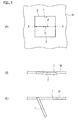
- a hole 1 When forming a hole 1 (see Fig 1 (A) ) on a plate-shaped workpiece W by a laser processing machine 10 (see Fig. 3 ), the hole 1 having a various shape such as circle or rectangle is formed by laser-cutting the workpiece W along an outline 3 (see Fig. 1(A) ) of the hole 1.
- a cutout piece 7 (see Fig. 1(B) and Fig. 1(C) ) may get stuck in the formed hole 1.
- a cutout piece 7 tends to get stuck when its diameter is not larger than 30mm (5 to 30 mm).
- a cutout piece 7 tends to get stuck when its minor axis is not larger than 30mm (5 to 30 mm). In a case of a rectangular hole, a cutout piece 7 tends to get stuck when its one side is not larger than 30mm (5 to 30 mm). Note that, since the laser processing machine 10 described hereinafter includes commonly known configurations except an after-described controller 11, detailed descriptions for the configurations of the laser processing machine 10 are omitted. The controller 11 will be described later in detail.
- Fig. 1 in a case of laser processing a rectangular (square) hole 1 whose one side is not larger than 30mm on a plate-shaped workpiece W, laser processing is started at an inside of an outline 3 of the hole 1.
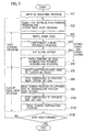
- Piercing is done at a position near a center position O or a centroid position of the hole 1 (hereinafter, descriptions will be made with the center position O taken as an example) (step S30 in Fig. 5 ), and then laser-cutting is done from the piercing position P to the outline 3 (step S40).
- the cutting line reaches the outline 3 (an intersect position 5 of the cutting line and the outline 3)
- the hole 1 is cut along the outline 3 (step S50).
- step S60 When cutting along the outline 3 goes around and then returns to the intersect position 5, cutting of the hole 1 is finished (step S60), and emitting of a laser light and jetting of assist gas are stopped. It doesn't matter to think that the intersect position 5 and the working-end position are identical to each other (although they are distanced by radius of a cross-sectional circle of the laser light). Therefore, it is regarded that the intersect position 5 and the working-end position are synonymous.
- the cutout piece 7 may incline and get stuck as shown in Fig. 1(B) .
- the portion of the cutout piece 7 near the working-end position 5 sufficiently moves downward, but a portion on an opposite side to the working-end position 5 may get stuck as shown in Fig. 1(C) .
- the cutout piece 7 that drops off from the hole 1 drops into a scrap box (not shown in the drawings).
- the cutout piece 7 may enter between a work table and the workpiece W when moving the workpiece W, and thereby a surface of the workpiece W may be scratched.
- the laser processing head 31 may contact with the cutout piece when moving the laser processing head 31.
- the laser processing is finished by stopping emitting of a laser light and jetting of assist gas when cutting for the hole 1 along the outline 3 reaches the working-end position 5. Then, the laser processing head 31 is moved toward an opposite side to the working-end position 5 from the working-end position 5 to a position near the center position O of the hole 1 without changing a height level of the laser processing head 31 (step S70). Note that the laser processing head 31 may be moved with respect to the workpiece W that remains stationary, or the workpiece W may be moved with respect to the laser processing head 31 that remains stationary. Otherwise, the laser processing head 31 is moved with respect to the workpiece W by moving both of them concurrently.
- the assist gas is jet, with a pressure equal-to or higher-than a pressure during the laser processing, from the laser processing head 31 at a position near the center position O (step S80).
- the laser processing head 31 When the laser processing head 31 reaches the position near the center position O, the laser processing head 31 is temporarily stopped and the assist gas is jet (step S80). Then, the laser processing head 31 is moved to the opposite side to the working-end position 5 while keeping on jetting the assist gas (step S90), and then temporarily stopped when it reaches the outline 3 on the opposite side or a position near it (hereinafter, it is called as an opposite-side position 9) (step S100). Subsequently, the laser processing head 31 is returned to the working-end position 5 while keeping on jetting the assist gas (step S31).
- the assist gas is jetted from the laser processing head 31. Then, when the laser processing head 31 is returned to the working-end position 5, jetting of the assist gas is stopped.
- the laser processing head 31 is moved from the working-end position 5 to the opposite-side position 9, the laser processing head 31 is temporarily stopped at the position near the center position O.
- the assist gas is jet for a preset time at this stop position. Therefore, in the case where the cutout piece 7 gets stuck as shown in Fig. 7(B), the assist gas is jet to the position near the center position O of the cutout piece 7, and thereby a pressure is applied first to the position near the center position O.
- the portion of the cutout piece 7 near the center position O is pushed downward, and thereby the cutout piece 7 drops off while it nearly keeps its horizontality.
- jetting of the assist gas is continued. Therefore, a position to which the pressure is applied changes, and thereby the cutout piece 7 can be surely dropped off while preventing the cutout piece 7 from swinging under its stuck state.
- the assist gas may be jet continuously or continually (pulsatingly).
- the assist gas is also jet while the laser processing head 31 is moved from the position near the center position 0 to the opposite-side position 9, and then the laser processing head 31 is temporarily stopped at the opposite-side position 9.
- the assist gas is jet intensively for the preset time in this stop state. Therefore, also in the case where the cutout piece 7 that already inclines preliminarily gets stuck at a position near the opposite-side position 9 as shown in Fig. 1(C) , the cutout piece 7 can be surely dropped off, because the assist gas is jet intensively to a portion of the cutout piece 7 near the opposite-side position 9.
- the laser processing head 31 is moved from the working-end position 5 to the position near the center position O after laser-processing of the hole 1, and then the assist gas is continuously jetted from the laser processing head 31 while moving the laser processing head 31 from the position near the center position 0 to the opposite-side position 9. According to this, the cutout piece 7 can be surely prevented from getting stuck.
- the assist gas is continuously jet also while moving the laser processing head 31 from the opposite-side position 9 to the working-end position 5. According to this, the cutout piece 7 can be more surely prevented from getting stuck.
- the assist gas may be jet also while the laser processing head 31 is moved from the working-end position 5 to the position near the center position 0 of the hole 1 after laser-processing of the hole 1.
- the assist gas is jet to the portion of the cutout piece 7 near the working-end position 5 as shown in Fig. 1(B) . Therefore, there may be a case where the portion of the cutout piece 7 near the working-end position 5 is pushed downward and then it is changed into the state shown in Fig. 1(C) .
- the above operation for dropping the cutout piece 7 off (moving the laser processing head 31 and jetting the assist gas) is carried out regardless of whether or not the cutout piece 7 gets stuck.
- the above operation for dropping the cutout piece 7 off is carried out automatically after forming the small hole 1 by laser processing.
- configurations for automatically carrying out the operation for dropping the cutout piece 7 off after forming the small hole 1 on the workpiece W by laser processing will be described.
- configurations in the laser processing machine 10 for moving the laser processing head 31 in a left-right direction (an X-axis direction), a front-rear direction (a Y-axis direction) and an up-down direction (a Z-axis direction) are commonly-known configurations, so that the controller 11 for controlling operations of the laser processing head 31 will be described in detail hereinafter.
- the controller 11 according to a first embodiment will be described.
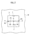
- a control of the laser processing head 31 for the above operation, e.g. for dropping the cutout piece 7 off includes an operation for moving it from the working-end position 5 to the position near the center position 0 (an operation A), an operation for temporarily stopping it at the position near the center position O (an operation B), an operation for jetting the assist gas at the position near the center position O (an operation C), an operation for moving it from the position near the center position O to the opposite-side position 9 (an operation D), an operation for temporarily stopping it at the opposite-side position 9 (an operation E), an operation for moving it from the opposite-side position 9 to the working-end position 5 (an operation F), and an operation for jetting the assist gas at the working-end position 5 (an operation G).
- the above operations A to G are shown in Fig. 2 .
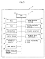
- FIG. 3 A schematic block diagram of the controller 11 that controls the operations A to G (the operations of the laser processing head 31 of the laser processing machine 10) is shown in Fig. 3 .
- the controller 11 is configured of a computer, and includes a CPU 13, a RAM 15, a ROM 17, an input device 19 and a display device 21.
- the controller 11 includes a first program storage 23.
- the first program storage 23 stores hole-forming programs for forming (cutting) a hole that may have predefined various shapes such as a circular hole, an elongated hole and a rectangular hole by laser processing.
- the hole-forming programs are prepared for every shape of the hole 1 to be cut and/or for every specification (material, thickness and so on) of the workpiece W, and, for example, a hole-shape code(s) that indicates a hole shape and the hole-forming program(s) are stored while being associated with each other.
- the controller 11 is provided with a second program storage 25.
- the second program storage 25 stores cutout piece drop programs that are associated with the program codes of the hole-forming programs and the hole shape codes that are stored in the first program storage 23.
- the operations A to G that correspond to a hole shape are preliminarily programmed. Namely, in the cutout piece drop program(s), a motion path of the laser processing head 31 and a jetting condition of the assist gas for moving the laser processing head 31 and jetting the assist gas to the cutout piece 7 inside the outline 3 of the hole 1 are set.
- the operations A to G associated with a square as shown in Fig. 2 are programmed.
- a shape of the hole 1 such as a rectangle, a circular hole and an elongated hole, and the above-described operations A to G are preliminarily programmed in the cutout piece drop program while being associated with the hole-forming program associated with each shape.
- an NC machining program including a hole shape code generated by an automatic programming machine or the like is supplied from the input device 19 to the controller 11 via a storage medium or a transfer device (step S10 in Fig. 5 ). Or, an NC machining program is directly input to the controller 11 by a keyboard or the like that serves as the input device 19.
- a hole-forming program associated with the hole code in the NC machining program is selected from the programs stored in the first program storage 23 by a program selector 27 of the controller 11 (step S20).
- the selected hole-forming program is fetched from the first program storage 23, and then the shape, the working-end position 5, the center position O (or the centroid position) and the opposite-side position 9 of the hole 1 to be cut (the cutout piece 7) are retrieved (or calculated) from the fetched hole-forming program. Then, the operations of the laser processing head 31 are controlled by a working head controller 29 according to the selected hole-forming program, and thereby the hole 1 is formed by laser processing (steps S30 to S60).
- the cutout piece drop program associated with the program code and the hole shape code of the selected hole-forming program is selected from the programs stored in the second program storage 25 (step S20). Then, the above-described operations A to G of the laser processing head 31 is controlled by the working head controller 29 according to the selected cutout piece drop program after the formation of the hole 1, and thereby the cutout piece 7 is dropped off (steps S70 to S100).
- the hole-forming program for forming the hole 1 by laser processing and the cutout piece drop program associated with the selected hole-forming program are selected when the NC machining program including the hole shape code associated with the desired-shaped hole 1 is input to the controller 11, and then the operations A to G for forming the hole 1 by laser processing and dropping the cutout piece 7 off are automatically carried out. Then, these processes are sequentially repeated for plural holes, so that formation of the holes 1 on the workpiece W and drop-off of the cutout pieces 7 can be done. Therefore, its handling is easy and laser processing for forming the plural holes 1 can be done efficiently.
- cutout piece drop program in which the operations A to G are preliminarily programmed with being associated with the hole-forming program is stored in the second program storage 25 in the present embodiment.
- a following configuration may be adopted.
- an appropriate speed parameter is selected from speed parameters preliminarily stored in a speed parameter memory 33, and then an appropriate speed is set.
- an appropriate time parameter is selected from time parameters preliminarily stored in a time parameter memory 35, and then an appropriate stop time is set.
- an appropriate jetting pressure parameter is selected from jetting pressure parameters preliminarily stored in a jetting pressure parameter memory 37, and then an appropriate jetting pressure is set.
- These settings of the parameters are done by inputting the selected parameters, by use of the input device 19, into portions displayed on the display device 21 that are associated with the above parameters of the operations A to G of the cutout piece drop program selected from the second program storage 25.
- a speed condition of the laser processing head 31, a jetting pressure condition of the assist gas, and a jetting time condition of the assist gas can be set more appropriately. Therefore, the cutout piece 7 can be dropped off more surely according to accuracy of a cut surface or the like, for example.
- the above-described operations A to G can be set independently according to accuracy of a cut surface, or difference of a stuck state caused by thickness of the workpiece W.
- controller 11A according to a second embodiment will be described. As shown in Fig. 4 , configurations that realize functions identical or equivalent to functions realized by the configurations of the controller 11 according to the first embodiment are labelled with identical signs, and their redundant descriptions will be omitted.
- the controller 11A of the present embodiment is significantly different from the controller 11 of the first embodiment in that the second program storage 25 is omitted and a program generator 39 is provided instead of it.
- the program generator 39 generates, by referring to the hole-forming program selected by the program selector 27, the cutout piece drop program for dropping the cutout piece 7 off from the hole 1 formed according to the hole-forming program.
- the hole-forming program associated with the hole code in the NC machining program is selected from the programs stored in the first program storage 23 (step S130 in Fig. 6 ). Then, the operations of the laser processing head 31 are controlled by the working head controller 29 according to the selected hole-forming program, and thereby the hole 1 is formed by laser processing (steps S30 to S60).
- the hole-forming program is prefetched by a program prefetcher 41 (step S130).
- a reference size of the hole 1 to be formed (a length of one side for a rectangular hole, a diameter for a circular hole, a length of a minor axis for an elongated hole) is retrieved by referring to various data in the hole-forming program prefetched by the program prefetcher 41.
- the opposite-side position 9 is calculated by an arithmetic unit 43 by referring to the working-end position 5 and the center position O in the hole-forming program.
- the above-described operations A to G are set by retrieving and calculating the working-end position 5, the center position O and the opposite-side position 9 based on the hole-forming program prefetched by the program prefetcher 41.
- the appropriate parameters are selected from the speed parameter memory 33, the time parameter memory 35 and the jetting pressure parameter memory 37, and thereby the cutout piece drop program associated with the hole-forming program is generated (step S150).
- the operations for dropping-off the cutout piece 7 are carried out according to the generated cutout piece drop program (steps S70 to S110).
- the cutout piece drop program may be generated every time when the hole-forming program is selected, or it is possible to prefetch all the hole-forming programs included in the NC machining program and then preliminarily generate and store the cutout piece drop programs associated with all the hole-forming programs.
- the cutout piece drop program associated with the hole-forming program of the hole 1 to be formed is selected to drop the cutout piece 7 off when the hole 1 is to be formed by laser processing according to the NC machining program.
- the above-described operations A to G are carried out according to the cutout piece drop program generated by referring to various data of the selected hole-forming program. Therefore, it is not needed to preliminarily prepare the cutout piece drop program associated with the hole-forming program. As the result, it is possible to easily execute the cutout piece drop program additionally after forming the hole 1 by the hole-forming program that is primarily prepared.
- the cutout piece 7 tends to get stuck in a case of forming a small rectangular hole having one side not larger than 30mm. Even in a case where the hole 1 is a circular hole, the cutout piece 7 may get stuck while it slightly inclines with respect to horizontal plane as shown in Fig. 1 (B) , and it tends to get stuck in this case when its diameter is not larger than 30mm. Therefore, the above-described operations A to G by the cutout piece drop program may be carried out for a case where the small hole 1 that tends to get the cutout piece 7 stuck is formed.
- a preset value e.g. 30mm
- the preset value in a case of a circular hole or an elongated hole, to determine whether its diameter or its minor axis is not larger than a preset value or is larger than the preset value
- step S150 in Fig. 7
- a shape and a dimension of the hole 1 to be formed are selected by the program selector 27, and can be judged from various data in the hole-forming program prefetched by the program prefetcher 41. Therefore, the shape and the dimension of the hole 1 are calculated by the arithmetic unit 43 by referring to the selected hole-forming program, and then, in a case of a rectangular hole, the length of the short side and the preset value preliminarily stored in a preset value memory 47 are compared with each other by the comparator 45 (it is determined whether or not the rectangular hole is the hole 1 that tends to get the cutout piece 7 stuck). In a case of a circular hole or an elongated hole, its diameter or its minor axis is compared with the preset value.
- a command signal for generating the cutout piece drop program associated with the selected hole-forming program is output from the comparator 45 to the program generator 39.
- the program generator 39 generates the cutout piece drop program associated with the selected hole-forming program when the command signal is input thereto.
- the cutout piece drop program is not generated for all the selected hole-forming programs, but the cutout piece drop program is generated only for the hole-forming program(s) that forms the small hole 1 that tends to get the cutout piece 7 stuck. Therefore, burdens to the controller 11A can be reduced, and thereby workings can be done efficiently in a case of forming the plural holes 1 on the workpiece W.
- the present invention is not limited to the above embodiments, but can be modified appropriately within a scope of the invention.
- the first program storage 23 (see Fig. 3 ) in the first embodiment and the program storage 23 (see Fig. 4 ) in the second embodiment store the hole-forming program(s).
- the hole-forming program may be directly selected from the NC machining program.
- the plural hole-forming programs may be extracted from the NC machining program, and then stored in the first program storage 23 or the program storage 23.
- the controller 11 in the first embodiment includes the first program storage 23, the second program storage 25 and the program selector 27.
- these components may be provided in an automatic programming machine that generates the NC machining program.
- the hole-forming program and the cutout piece drop program are preliminarily included in the NC machining program generated by the automatic programming machine.
- the NC machining program is supplied to the controller 11 and then executed, so that the hole 1 is formed and the cutout piece 7 is dropped off.
- the controller 11A in the second embodiment includes the program storage 23, the program selector 27, the program generator 39, the program prefetcher 41, the arithmetic unit 43 and the comparator 45. Similarly, these components may be provided in an automatic programming machine that generates the NC machining program.
- the jetting pressure of the assist gas jetted from the laser processing head may be increased.
- plural cutout piece drop nozzles that jet high-pressure air (the assist gas) may be provided around the nozzle of the laser processing head to drop the cutout piece 7 off by the high-pressure air jetted from the cutout piece drop nozzles.
- the cutout piece is dropped off by effectively using the jetting function of the assist gas jetted from the laser processing head in laser processing.
Landscapes
- Engineering & Computer Science (AREA)
- Physics & Mathematics (AREA)
- Optics & Photonics (AREA)
- Mechanical Engineering (AREA)
- Plasma & Fusion (AREA)
- General Physics & Mathematics (AREA)
- Automation & Control Theory (AREA)
- Manufacturing & Machinery (AREA)
- Human Computer Interaction (AREA)
- Chemical & Material Sciences (AREA)
- Chemical Kinetics & Catalysis (AREA)
- General Chemical & Material Sciences (AREA)
- Oil, Petroleum & Natural Gas (AREA)
- Laser Beam Processing (AREA)
Applications Claiming Priority (3)
| Application Number | Priority Date | Filing Date | Title |
|---|---|---|---|
| JP2013245635A JP6190705B2 (ja) | 2013-11-28 | 2013-11-28 | レーザ加工方法 |
| JP2013247033A JP6190708B2 (ja) | 2013-11-29 | 2013-11-29 | レーザ加工方法及び装置 |
| PCT/JP2014/079559 WO2015079889A1 (ja) | 2013-11-28 | 2014-11-07 | レーザ加工方法及びレーザ加工機 |
Publications (3)
| Publication Number | Publication Date |
|---|---|
| EP3075485A1 true EP3075485A1 (de) | 2016-10-05 |
| EP3075485A4 EP3075485A4 (de) | 2017-09-06 |
| EP3075485B1 EP3075485B1 (de) | 2018-07-18 |
Family
ID=53198837
Family Applications (1)
| Application Number | Title | Priority Date | Filing Date |
|---|---|---|---|
| EP14865811.5A Active EP3075485B1 (de) | 2013-11-28 | 2014-11-07 | Laserbearbeitungsverfahren und laserbearbeitungsmaschinen |
Country Status (3)
| Country | Link |
|---|---|
| US (2) | US10086476B2 (de) |
| EP (1) | EP3075485B1 (de) |
| WO (1) | WO2015079889A1 (de) |
Cited By (1)
| Publication number | Priority date | Publication date | Assignee | Title |
|---|---|---|---|---|
| WO2018073215A3 (de) * | 2016-10-19 | 2018-07-19 | Trumpf Werkzeugmaschinen Gmbh + Co. Kg | Verfahren und maschine zum schneidenden bearbeiten eines werkstücks |
Families Citing this family (5)
| Publication number | Priority date | Publication date | Assignee | Title |
|---|---|---|---|---|
| EP3075485B1 (de) * | 2013-11-28 | 2018-07-18 | Amada Holdings Co., Ltd. | Laserbearbeitungsverfahren und laserbearbeitungsmaschinen |
| DE102016208872A1 (de) * | 2016-05-23 | 2017-11-23 | Trumpf Werkzeugmaschinen Gmbh + Co. Kg | Maschine zum trennenden Bearbeiten eines plattenförmigen Werkstücks und Verfahren zum Ausdrücken eines freigetrennten Werkstückteils |
| US11407067B2 (en) * | 2018-06-29 | 2022-08-09 | Pratt & Whitney Canada Corp. | Method for repairing a part |
| JP6643439B1 (ja) * | 2018-09-27 | 2020-02-12 | 株式会社アマダホールディングス | レーザ加工方法、レーザ加工装置、及びレーザ加工品の製造方法 |
| DE102018217200A1 (de) * | 2018-10-09 | 2020-04-09 | Trumpf Werkzeugmaschinen Gmbh + Co. Kg | Verfahren und Bearbeitungsmaschine zum Schneiden von Werkstücken sowie zugehöriges Computerprogrammprodukt |
Family Cites Families (24)
| Publication number | Priority date | Publication date | Assignee | Title |
|---|---|---|---|---|
| US2747259A (en) * | 1952-04-23 | 1956-05-29 | Baker & Co Inc | Method of forming a ring having embedded metal inserts therein |
| JPS5843884A (ja) | 1981-09-11 | 1983-03-14 | ヤマハ発動機株式会社 | 自動二輪車の後輪懸架装置 |
| JPS5843884U (ja) * | 1981-09-11 | 1983-03-24 | 株式会社東芝 | 金属板切断装置 |
| JPH04367391A (ja) | 1991-06-13 | 1992-12-18 | Amada Co Ltd | レーザ加工機における切断片分離装置 |
| JP3128269B2 (ja) | 1991-07-04 | 2001-01-29 | 旭化成工業株式会社 | 塩化アルカリ水溶液電解槽 |
| JP2548520Y2 (ja) * | 1991-07-18 | 1997-09-24 | 関東自動車工業株式会社 | レーザー穴明加工装置 |
| JPH0542491A (ja) * | 1991-08-15 | 1993-02-23 | Fanuc Ltd | 磁気吸着ワーク屑の取外し装置 |
| US5223692A (en) * | 1991-09-23 | 1993-06-29 | General Electric Company | Method and apparatus for laser trepanning |
| JPH09271977A (ja) * | 1996-04-02 | 1997-10-21 | Nippei Toyama Corp | 加工用制御プログラム作成装置 |
| JPH09295084A (ja) * | 1996-05-10 | 1997-11-18 | Amada Co Ltd | 板金加工機におけるワークシュータ |
| JPH11267877A (ja) * | 1998-03-24 | 1999-10-05 | Amada Co Ltd | アシストガス放出手段 |
| CN100347537C (zh) * | 1999-11-15 | 2007-11-07 | 松下电器产业株式会社 | 生物传感器 |
| JP2005169465A (ja) | 2003-12-11 | 2005-06-30 | Sumitomo Heavy Ind Ltd | レーザ加工方法、レーザ加工装置、及びレーザ加工プログラム |
| US7419083B1 (en) * | 2004-04-22 | 2008-09-02 | Angela Cheng | Method for metal ornamentation |
| DE102004039023A1 (de) | 2004-08-11 | 2006-02-23 | Siemens Ag | Verfahren zur Bearbeitung eines Werkstücks mittels Laserstrahlung, Laserbearbeitungssystem |
| US7552855B2 (en) * | 2005-10-13 | 2009-06-30 | United Technologies Corporation | Hole repair technique and apparatus |
| JP4997452B2 (ja) * | 2006-08-22 | 2012-08-08 | 三菱電機株式会社 | レーザ加工装置、骨の接合方法、インプラント材、インプラント材製造方法およびインプラント材製造装置 |
| US7858897B2 (en) * | 2006-10-27 | 2010-12-28 | United Technologies Corporation | Insert weld repair |
| KR101319359B1 (ko) * | 2009-05-29 | 2013-10-16 | 가부시끼가이샤 도시바 | 응력 처리 장치, 시공 시스템 및 터빈 제조 방법 |
| US8679394B2 (en) | 2010-06-10 | 2014-03-25 | Abbott Cardiovascular Systems Inc. | Laser system and processing conditions for manufacturing bioabsorbable stents |
| KR101299783B1 (ko) * | 2011-09-02 | 2013-08-23 | 대구텍 유한회사 | 절삭 인서트 |
| US8746115B2 (en) * | 2012-01-09 | 2014-06-10 | Iscar, Ltd. | Cutting insert having hole orientation indicia and method for making thereof |
| DE102013210857B3 (de) * | 2013-06-11 | 2014-08-21 | Trumpf Werkzeugmaschinen Gmbh + Co. Kg | Verfahren zum Einstechen in metallische Werkstücke mittels eines Laserstrahls |
| EP3075485B1 (de) * | 2013-11-28 | 2018-07-18 | Amada Holdings Co., Ltd. | Laserbearbeitungsverfahren und laserbearbeitungsmaschinen |
-
2014
- 2014-11-07 EP EP14865811.5A patent/EP3075485B1/de active Active
- 2014-11-07 WO PCT/JP2014/079559 patent/WO2015079889A1/ja not_active Ceased
- 2014-11-07 US US15/035,928 patent/US10086476B2/en active Active
-
2017
- 2017-12-22 US US15/853,098 patent/US10131019B2/en active Active
Cited By (6)
| Publication number | Priority date | Publication date | Assignee | Title |
|---|---|---|---|---|
| WO2018073215A3 (de) * | 2016-10-19 | 2018-07-19 | Trumpf Werkzeugmaschinen Gmbh + Co. Kg | Verfahren und maschine zum schneidenden bearbeiten eines werkstücks |
| CN109862990A (zh) * | 2016-10-19 | 2019-06-07 | 通快机床两合公司 | 用于切割加工工件的方法和机器 |
| EP3636379A1 (de) * | 2016-10-19 | 2020-04-15 | TRUMPF Werkzeugmaschinen GmbH + Co. KG | Verfahren und maschine zum schneidenden bearbeiten eines werkstücks |
| US10843296B2 (en) | 2016-10-19 | 2020-11-24 | Trumpf Werkzeugmaschinen Gmbh + Co. Kg | Cutting a workpiece |
| US11420292B2 (en) | 2016-10-19 | 2022-08-23 | Trumpf Werkzeugmaschinen Gmbh + Co. Kg | Cutting a workpiece |
| EP4559614A3 (de) * | 2016-10-19 | 2025-08-20 | TRUMPF Werkzeugmaschinen SE + Co. KG | Verfahren und maschine zum schneidenden bearbeiten eines werkstücks |
Also Published As
| Publication number | Publication date |
|---|---|
| EP3075485B1 (de) | 2018-07-18 |
| US20180111230A1 (en) | 2018-04-26 |
| US20160297033A1 (en) | 2016-10-13 |
| WO2015079889A1 (ja) | 2015-06-04 |
| US10131019B2 (en) | 2018-11-20 |
| US10086476B2 (en) | 2018-10-02 |
| EP3075485A4 (de) | 2017-09-06 |
Similar Documents
| Publication | Publication Date | Title |
|---|---|---|
| US10131019B2 (en) | Laser processing method and laser processing machine | |
| JP5888826B1 (ja) | 積層造形装置 | |
| JP5752335B1 (ja) | Ncプログラム生成装置、ncプログラム生成方法、ncプログラム生成プログラム | |
| US20160184951A1 (en) | Cutting fluid supply system to machine tool | |
| JP2018183793A (ja) | レーザ加工装置及びレーザ加工方法 | |
| JP6225001B2 (ja) | レーザ切断加工方法及び装置並びに自動プログラミング装置 | |
| CN104375456A (zh) | 一种干涉确认装置 | |
| JP6195659B2 (ja) | 加工プログラムの生成方法、経路生成装置および放電加工機 | |
| JP5369205B2 (ja) | 切込み加工時、逃げ加工時の加工傷を低減するワイヤ放電加工機およびワイヤ放電加工方法 | |
| JP5201114B2 (ja) | レーザ加工装置およびレーザ加工方法 | |
| JPH10244394A (ja) | レーザ加工機におけるスクラップ排出方法およびその装置 | |
| JP5909355B2 (ja) | レーザ加工機の自動プログラミング装置及びその方法およびレーザ加工システム | |
| JP2008200809A (ja) | パンチ加工用プログラム作成装置及びパンチ加工用プログラム作成用のプログラムを記憶した記録媒体並びにワイヤカット放電加工機 | |
| WO2022254671A1 (ja) | 付加製造装置および付加製造方法 | |
| JP6190708B2 (ja) | レーザ加工方法及び装置 | |
| US12370627B2 (en) | Laser machining apparatus, laser machining method, and processing program creation device | |
| JP2008212955A (ja) | レーザ加工装置、レーザ加工方法、プログラミング装置およびプログラミング方法 | |
| JP2021030245A (ja) | プラズマ切断機、及びプラズマ切断機を制御するための方法 | |
| JP6190705B2 (ja) | レーザ加工方法 | |
| JP2018103251A (ja) | レーザ加工機及びレーザ加工方法 | |
| JP2014188558A (ja) | 切断方法及び切断装置 | |
| JP2019072747A (ja) | レーザ加工機及びその騒音警告方法 | |
| JP2005169465A (ja) | レーザ加工方法、レーザ加工装置、及びレーザ加工プログラム | |
| JP2650166B2 (ja) | レーザ加工の加工形状設定装置 | |
| JP2005198814A (ja) | ミシン |
Legal Events
| Date | Code | Title | Description |
|---|---|---|---|
| PUAI | Public reference made under article 153(3) epc to a published international application that has entered the european phase |
Free format text: ORIGINAL CODE: 0009012 |
|
| 17P | Request for examination filed |
Effective date: 20160621 |
|
| AK | Designated contracting states |
Kind code of ref document: A1 Designated state(s): AL AT BE BG CH CY CZ DE DK EE ES FI FR GB GR HR HU IE IS IT LI LT LU LV MC MK MT NL NO PL PT RO RS SE SI SK SM TR |
|
| AX | Request for extension of the european patent |
Extension state: BA ME |
|
| DAX | Request for extension of the european patent (deleted) | ||
| A4 | Supplementary search report drawn up and despatched |
Effective date: 20170808 |
|
| RIC1 | Information provided on ipc code assigned before grant |
Ipc: B23K 26/08 20140101ALI20170802BHEP Ipc: G05B 19/18 20060101ALI20170802BHEP Ipc: B23K 26/142 20140101ALI20170802BHEP Ipc: B23Q 7/00 20060101ALI20170802BHEP Ipc: B23K 26/382 20140101AFI20170802BHEP Ipc: B23K 26/16 20060101ALI20170802BHEP Ipc: B23K 26/38 20140101ALI20170802BHEP |
|
| GRAP | Despatch of communication of intention to grant a patent |
Free format text: ORIGINAL CODE: EPIDOSNIGR1 |
|
| RIC1 | Information provided on ipc code assigned before grant |
Ipc: B23K 26/16 20060101ALI20180118BHEP Ipc: B23Q 7/00 20060101ALI20180118BHEP Ipc: B23K 26/142 20140101ALI20180118BHEP Ipc: B23K 26/38 20140101ALI20180118BHEP Ipc: G05B 19/18 20060101ALI20180118BHEP Ipc: B23K 26/08 20140101ALI20180118BHEP Ipc: B23K 26/382 20140101AFI20180118BHEP |
|
| INTG | Intention to grant announced |
Effective date: 20180208 |
|
| GRAS | Grant fee paid |
Free format text: ORIGINAL CODE: EPIDOSNIGR3 |
|
| GRAA | (expected) grant |
Free format text: ORIGINAL CODE: 0009210 |
|
| AK | Designated contracting states |
Kind code of ref document: B1 Designated state(s): AL AT BE BG CH CY CZ DE DK EE ES FI FR GB GR HR HU IE IS IT LI LT LU LV MC MK MT NL NO PL PT RO RS SE SI SK SM TR |
|
| REG | Reference to a national code |
Ref country code: GB Ref legal event code: FG4D |
|
| REG | Reference to a national code |
Ref country code: CH Ref legal event code: EP |
|
| REG | Reference to a national code |
Ref country code: IE Ref legal event code: FG4D |
|
| REG | Reference to a national code |
Ref country code: AT Ref legal event code: REF Ref document number: 1018840 Country of ref document: AT Kind code of ref document: T Effective date: 20180815 |
|
| REG | Reference to a national code |
Ref country code: DE Ref legal event code: R096 Ref document number: 602014028922 Country of ref document: DE |
|
| REG | Reference to a national code |
Ref country code: NL Ref legal event code: MP Effective date: 20180718 |
|
| REG | Reference to a national code |
Ref country code: LT Ref legal event code: MG4D |
|
| REG | Reference to a national code |
Ref country code: AT Ref legal event code: MK05 Ref document number: 1018840 Country of ref document: AT Kind code of ref document: T Effective date: 20180718 |
|
| PG25 | Lapsed in a contracting state [announced via postgrant information from national office to epo] |
Ref country code: NL Free format text: LAPSE BECAUSE OF FAILURE TO SUBMIT A TRANSLATION OF THE DESCRIPTION OR TO PAY THE FEE WITHIN THE PRESCRIBED TIME-LIMIT Effective date: 20180718 |
|
| PG25 | Lapsed in a contracting state [announced via postgrant information from national office to epo] |
Ref country code: GR Free format text: LAPSE BECAUSE OF FAILURE TO SUBMIT A TRANSLATION OF THE DESCRIPTION OR TO PAY THE FEE WITHIN THE PRESCRIBED TIME-LIMIT Effective date: 20181019 Ref country code: BG Free format text: LAPSE BECAUSE OF FAILURE TO SUBMIT A TRANSLATION OF THE DESCRIPTION OR TO PAY THE FEE WITHIN THE PRESCRIBED TIME-LIMIT Effective date: 20181018 Ref country code: NO Free format text: LAPSE BECAUSE OF FAILURE TO SUBMIT A TRANSLATION OF THE DESCRIPTION OR TO PAY THE FEE WITHIN THE PRESCRIBED TIME-LIMIT Effective date: 20181018 Ref country code: AT Free format text: LAPSE BECAUSE OF FAILURE TO SUBMIT A TRANSLATION OF THE DESCRIPTION OR TO PAY THE FEE WITHIN THE PRESCRIBED TIME-LIMIT Effective date: 20180718 Ref country code: PL Free format text: LAPSE BECAUSE OF FAILURE TO SUBMIT A TRANSLATION OF THE DESCRIPTION OR TO PAY THE FEE WITHIN THE PRESCRIBED TIME-LIMIT Effective date: 20180718 Ref country code: IS Free format text: LAPSE BECAUSE OF FAILURE TO SUBMIT A TRANSLATION OF THE DESCRIPTION OR TO PAY THE FEE WITHIN THE PRESCRIBED TIME-LIMIT Effective date: 20181118 Ref country code: RS Free format text: LAPSE BECAUSE OF FAILURE TO SUBMIT A TRANSLATION OF THE DESCRIPTION OR TO PAY THE FEE WITHIN THE PRESCRIBED TIME-LIMIT Effective date: 20180718 Ref country code: FI Free format text: LAPSE BECAUSE OF FAILURE TO SUBMIT A TRANSLATION OF THE DESCRIPTION OR TO PAY THE FEE WITHIN THE PRESCRIBED TIME-LIMIT Effective date: 20180718 Ref country code: LT Free format text: LAPSE BECAUSE OF FAILURE TO SUBMIT A TRANSLATION OF THE DESCRIPTION OR TO PAY THE FEE WITHIN THE PRESCRIBED TIME-LIMIT Effective date: 20180718 Ref country code: SE Free format text: LAPSE BECAUSE OF FAILURE TO SUBMIT A TRANSLATION OF THE DESCRIPTION OR TO PAY THE FEE WITHIN THE PRESCRIBED TIME-LIMIT Effective date: 20180718 |
|
| PG25 | Lapsed in a contracting state [announced via postgrant information from national office to epo] |
Ref country code: AL Free format text: LAPSE BECAUSE OF FAILURE TO SUBMIT A TRANSLATION OF THE DESCRIPTION OR TO PAY THE FEE WITHIN THE PRESCRIBED TIME-LIMIT Effective date: 20180718 Ref country code: HR Free format text: LAPSE BECAUSE OF FAILURE TO SUBMIT A TRANSLATION OF THE DESCRIPTION OR TO PAY THE FEE WITHIN THE PRESCRIBED TIME-LIMIT Effective date: 20180718 Ref country code: LV Free format text: LAPSE BECAUSE OF FAILURE TO SUBMIT A TRANSLATION OF THE DESCRIPTION OR TO PAY THE FEE WITHIN THE PRESCRIBED TIME-LIMIT Effective date: 20180718 |
|
| REG | Reference to a national code |
Ref country code: DE Ref legal event code: R097 Ref document number: 602014028922 Country of ref document: DE |
|
| PG25 | Lapsed in a contracting state [announced via postgrant information from national office to epo] |
Ref country code: EE Free format text: LAPSE BECAUSE OF FAILURE TO SUBMIT A TRANSLATION OF THE DESCRIPTION OR TO PAY THE FEE WITHIN THE PRESCRIBED TIME-LIMIT Effective date: 20180718 Ref country code: CZ Free format text: LAPSE BECAUSE OF FAILURE TO SUBMIT A TRANSLATION OF THE DESCRIPTION OR TO PAY THE FEE WITHIN THE PRESCRIBED TIME-LIMIT Effective date: 20180718 Ref country code: ES Free format text: LAPSE BECAUSE OF FAILURE TO SUBMIT A TRANSLATION OF THE DESCRIPTION OR TO PAY THE FEE WITHIN THE PRESCRIBED TIME-LIMIT Effective date: 20180718 Ref country code: RO Free format text: LAPSE BECAUSE OF FAILURE TO SUBMIT A TRANSLATION OF THE DESCRIPTION OR TO PAY THE FEE WITHIN THE PRESCRIBED TIME-LIMIT Effective date: 20180718 |
|
| PLBE | No opposition filed within time limit |
Free format text: ORIGINAL CODE: 0009261 |
|
| STAA | Information on the status of an ep patent application or granted ep patent |
Free format text: STATUS: NO OPPOSITION FILED WITHIN TIME LIMIT |
|
| PG25 | Lapsed in a contracting state [announced via postgrant information from national office to epo] |
Ref country code: SM Free format text: LAPSE BECAUSE OF FAILURE TO SUBMIT A TRANSLATION OF THE DESCRIPTION OR TO PAY THE FEE WITHIN THE PRESCRIBED TIME-LIMIT Effective date: 20180718 Ref country code: DK Free format text: LAPSE BECAUSE OF FAILURE TO SUBMIT A TRANSLATION OF THE DESCRIPTION OR TO PAY THE FEE WITHIN THE PRESCRIBED TIME-LIMIT Effective date: 20180718 Ref country code: SK Free format text: LAPSE BECAUSE OF FAILURE TO SUBMIT A TRANSLATION OF THE DESCRIPTION OR TO PAY THE FEE WITHIN THE PRESCRIBED TIME-LIMIT Effective date: 20180718 |
|
| 26N | No opposition filed |
Effective date: 20190423 |
|
| REG | Reference to a national code |
Ref country code: CH Ref legal event code: PL |
|
| PG25 | Lapsed in a contracting state [announced via postgrant information from national office to epo] |
Ref country code: LU Free format text: LAPSE BECAUSE OF NON-PAYMENT OF DUE FEES Effective date: 20181107 Ref country code: MC Free format text: LAPSE BECAUSE OF FAILURE TO SUBMIT A TRANSLATION OF THE DESCRIPTION OR TO PAY THE FEE WITHIN THE PRESCRIBED TIME-LIMIT Effective date: 20180718 |
|
| REG | Reference to a national code |
Ref country code: BE Ref legal event code: MM Effective date: 20181130 |
|
| REG | Reference to a national code |
Ref country code: IE Ref legal event code: MM4A |
|
| PG25 | Lapsed in a contracting state [announced via postgrant information from national office to epo] |
Ref country code: LI Free format text: LAPSE BECAUSE OF NON-PAYMENT OF DUE FEES Effective date: 20181130 Ref country code: CH Free format text: LAPSE BECAUSE OF NON-PAYMENT OF DUE FEES Effective date: 20181130 Ref country code: SI Free format text: LAPSE BECAUSE OF FAILURE TO SUBMIT A TRANSLATION OF THE DESCRIPTION OR TO PAY THE FEE WITHIN THE PRESCRIBED TIME-LIMIT Effective date: 20180718 |
|
| PG25 | Lapsed in a contracting state [announced via postgrant information from national office to epo] |
Ref country code: IE Free format text: LAPSE BECAUSE OF NON-PAYMENT OF DUE FEES Effective date: 20181107 |
|
| PG25 | Lapsed in a contracting state [announced via postgrant information from national office to epo] |
Ref country code: BE Free format text: LAPSE BECAUSE OF NON-PAYMENT OF DUE FEES Effective date: 20181130 |
|
| PG25 | Lapsed in a contracting state [announced via postgrant information from national office to epo] |
Ref country code: MT Free format text: LAPSE BECAUSE OF NON-PAYMENT OF DUE FEES Effective date: 20181107 |
|
| PG25 | Lapsed in a contracting state [announced via postgrant information from national office to epo] |
Ref country code: TR Free format text: LAPSE BECAUSE OF FAILURE TO SUBMIT A TRANSLATION OF THE DESCRIPTION OR TO PAY THE FEE WITHIN THE PRESCRIBED TIME-LIMIT Effective date: 20180718 |
|
| PG25 | Lapsed in a contracting state [announced via postgrant information from national office to epo] |
Ref country code: PT Free format text: LAPSE BECAUSE OF FAILURE TO SUBMIT A TRANSLATION OF THE DESCRIPTION OR TO PAY THE FEE WITHIN THE PRESCRIBED TIME-LIMIT Effective date: 20180718 |
|
| PG25 | Lapsed in a contracting state [announced via postgrant information from national office to epo] |
Ref country code: CY Free format text: LAPSE BECAUSE OF FAILURE TO SUBMIT A TRANSLATION OF THE DESCRIPTION OR TO PAY THE FEE WITHIN THE PRESCRIBED TIME-LIMIT Effective date: 20180718 Ref country code: HU Free format text: LAPSE BECAUSE OF FAILURE TO SUBMIT A TRANSLATION OF THE DESCRIPTION OR TO PAY THE FEE WITHIN THE PRESCRIBED TIME-LIMIT; INVALID AB INITIO Effective date: 20141107 Ref country code: MK Free format text: LAPSE BECAUSE OF NON-PAYMENT OF DUE FEES Effective date: 20180718 |
|
| P01 | Opt-out of the competence of the unified patent court (upc) registered |
Effective date: 20230428 |
|
| PGFP | Annual fee paid to national office [announced via postgrant information from national office to epo] |
Ref country code: DE Payment date: 20251119 Year of fee payment: 12 |
|
| PGFP | Annual fee paid to national office [announced via postgrant information from national office to epo] |
Ref country code: GB Payment date: 20251120 Year of fee payment: 12 |
|
| PGFP | Annual fee paid to national office [announced via postgrant information from national office to epo] |
Ref country code: IT Payment date: 20251125 Year of fee payment: 12 |
|
| PGFP | Annual fee paid to national office [announced via postgrant information from national office to epo] |
Ref country code: FR Payment date: 20251126 Year of fee payment: 12 |