EP3076106A2 - Unite de refroidissement - Google Patents
Unite de refroidissement Download PDFInfo
- Publication number
- EP3076106A2 EP3076106A2 EP16155198.1A EP16155198A EP3076106A2 EP 3076106 A2 EP3076106 A2 EP 3076106A2 EP 16155198 A EP16155198 A EP 16155198A EP 3076106 A2 EP3076106 A2 EP 3076106A2
- Authority
- EP
- European Patent Office
- Prior art keywords
- cooling
- unit
- cooling unit
- insulation
- advantageously
- Prior art date
- Legal status (The legal status is an assumption and is not a legal conclusion. Google has not performed a legal analysis and makes no representation as to the accuracy of the status listed.)
- Granted
Links
Images



Classifications
-
- F—MECHANICAL ENGINEERING; LIGHTING; HEATING; WEAPONS; BLASTING
- F25—REFRIGERATION OR COOLING; COMBINED HEATING AND REFRIGERATION SYSTEMS; HEAT PUMP SYSTEMS; MANUFACTURE OR STORAGE OF ICE; LIQUEFACTION SOLIDIFICATION OF GASES
- F25D—REFRIGERATORS; COLD ROOMS; ICE-BOXES; COOLING OR FREEZING APPARATUS NOT OTHERWISE PROVIDED FOR
- F25D21/00—Defrosting; Preventing frosting; Removing condensed or defrost water
- F25D21/04—Preventing the formation of frost or condensate
-
- A—HUMAN NECESSITIES
- A47—FURNITURE; DOMESTIC ARTICLES OR APPLIANCES; COFFEE MILLS; SPICE MILLS; SUCTION CLEANERS IN GENERAL
- A47F—SPECIAL FURNITURE, FITTINGS, OR ACCESSORIES FOR SHOPS, STOREHOUSES, BARS, RESTAURANTS OR THE LIKE; PAYING COUNTERS
- A47F3/00—Show cases or show cabinets
- A47F3/04—Show cases or show cabinets air-conditioned, refrigerated
- A47F3/0439—Cases or cabinets of the open type
- A47F3/0443—Cases or cabinets of the open type with forced air circulation
- A47F3/0447—Cases or cabinets of the open type with forced air circulation with air curtains
-
- A—HUMAN NECESSITIES
- A47—FURNITURE; DOMESTIC ARTICLES OR APPLIANCES; COFFEE MILLS; SPICE MILLS; SUCTION CLEANERS IN GENERAL
- A47F—SPECIAL FURNITURE, FITTINGS, OR ACCESSORIES FOR SHOPS, STOREHOUSES, BARS, RESTAURANTS OR THE LIKE; PAYING COUNTERS
- A47F3/00—Show cases or show cabinets
- A47F3/04—Show cases or show cabinets air-conditioned, refrigerated
- A47F3/0478—Control or safety arrangements
-
- F—MECHANICAL ENGINEERING; LIGHTING; HEATING; WEAPONS; BLASTING
- F25—REFRIGERATION OR COOLING; COMBINED HEATING AND REFRIGERATION SYSTEMS; HEAT PUMP SYSTEMS; MANUFACTURE OR STORAGE OF ICE; LIQUEFACTION SOLIDIFICATION OF GASES
- F25D—REFRIGERATORS; COLD ROOMS; ICE-BOXES; COOLING OR FREEZING APPARATUS NOT OTHERWISE PROVIDED FOR
- F25D13/00—Stationary devices, e.g. cold-rooms
-
- F—MECHANICAL ENGINEERING; LIGHTING; HEATING; WEAPONS; BLASTING
- F25—REFRIGERATION OR COOLING; COMBINED HEATING AND REFRIGERATION SYSTEMS; HEAT PUMP SYSTEMS; MANUFACTURE OR STORAGE OF ICE; LIQUEFACTION SOLIDIFICATION OF GASES
- F25D—REFRIGERATORS; COLD ROOMS; ICE-BOXES; COOLING OR FREEZING APPARATUS NOT OTHERWISE PROVIDED FOR
- F25D2201/00—Insulation
- F25D2201/10—Insulation with respect to heat
- F25D2201/12—Insulation with respect to heat using an insulating packing material
-
- F—MECHANICAL ENGINEERING; LIGHTING; HEATING; WEAPONS; BLASTING
- F25—REFRIGERATION OR COOLING; COMBINED HEATING AND REFRIGERATION SYSTEMS; HEAT PUMP SYSTEMS; MANUFACTURE OR STORAGE OF ICE; LIQUEFACTION SOLIDIFICATION OF GASES
- F25D—REFRIGERATORS; COLD ROOMS; ICE-BOXES; COOLING OR FREEZING APPARATUS NOT OTHERWISE PROVIDED FOR
- F25D2400/00—General features of, or devices for refrigerators, cold rooms, ice-boxes, or for cooling or freezing apparatus not covered by any other subclass
- F25D2400/14—Refrigerator multi units
-
- F—MECHANICAL ENGINEERING; LIGHTING; HEATING; WEAPONS; BLASTING
- F25—REFRIGERATION OR COOLING; COMBINED HEATING AND REFRIGERATION SYSTEMS; HEAT PUMP SYSTEMS; MANUFACTURE OR STORAGE OF ICE; LIQUEFACTION SOLIDIFICATION OF GASES
- F25D—REFRIGERATORS; COLD ROOMS; ICE-BOXES; COOLING OR FREEZING APPARATUS NOT OTHERWISE PROVIDED FOR
- F25D2400/00—General features of, or devices for refrigerators, cold rooms, ice-boxes, or for cooling or freezing apparatus not covered by any other subclass
- F25D2400/22—Cleaning means for refrigerating devices
-
- F—MECHANICAL ENGINEERING; LIGHTING; HEATING; WEAPONS; BLASTING
- F25—REFRIGERATION OR COOLING; COMBINED HEATING AND REFRIGERATION SYSTEMS; HEAT PUMP SYSTEMS; MANUFACTURE OR STORAGE OF ICE; LIQUEFACTION SOLIDIFICATION OF GASES
- F25D—REFRIGERATORS; COLD ROOMS; ICE-BOXES; COOLING OR FREEZING APPARATUS NOT OTHERWISE PROVIDED FOR
- F25D29/00—Arrangement or mounting of control or safety devices
- F25D29/005—Mounting of control devices
Definitions
- throttle bodies are provided for controlling the mass flow and thus also for the heat removal from the goods compartment to be cooled.
- the object of the present invention is to provide a cooling unit whose control unit avoids ice formation on the throttle elements, which is known from the prior art, and / or a wetting of the insulation.
- control unit during operation has a self-temperature in the range of -20 ° C to 25 ° C, more advantageously depending on the refrigerator temperature in the range of 0.25 K to 20 K higher than the refrigerator temperature, so that during operation of the Control unit, which also at the same time corresponds to the operation of the cooling unit, the temperature of the control unit is always equal to or higher than the temperature of the liquefied cooling medium and / or the expanded cooling medium.
- cooling unit is hydraulically balanced optimally.
- the basis of the hydraulic balancing is a corresponding design of the cooling network via pipe network calculation programs.
- the cooling capacity of the individual cooling units, as well as the pressure losses of all components of the pipe network, must be known.
- Hydraulic balancing is lacking in the prior art, so that certain cooling units, which are close to the cold generator, are oversupplied and under-supplied cooling units, which are not related to the cold generator.
- a supplier of refrigerants is advantageously understood to mean a device which conveys the cooling medium, for example a heat pump whose cooling medium or cooling carrier is selected as brine.
- control unit is designed as a pump arrangement.
- An advantage of Pump arrangement is that this emits heat energy during operation. This self-heat prevents the pump assembly itself from sweating or icing.
- Another advantage is also that the dew point is raised due to the self-heating in electrical control units, in particular by a pump assembly. This means that due to the self-heating of the control unit, the temperature, in particular in the housing of the pump assembly is raised to a temperature, so that no moisture can precipitate within the housing of the pump. Consequently, during operation of the pump assembly, which also corresponds to the operation of the cooling unit, the temperature in and / or on the housing of the pump assembly is always higher than the dew point temperature in the goods compartment to be cooled.
- control unit advantageously the pump assembly, additionally and / or alternatively in the ventilation flow of the heat exchanger of the cooling unit, so that the control unit is at least during operation in addition by means of the ventilation flow of the heat exchanger free of sweat and / or free of ice.
- the cooling units described here also comprise at least one local control device which regulates and / or controls, for example, the flow rate of the pump arrangement or the mass flow of the throttle body.
- This control device can be integrated in both the pump arrangement and / or the throttle element and / or be arranged separately in the cooling unit and / or outside the cooling unit.
- the control device is advantageously designed such that it controls the local control units within the cooling unit and also increases or reduces the delivery height of the central cooling medium delivery pump and / or decentralized pump arrangement as needed.
- both sensor elements are connected via an interface with the control unit.
- This can be wired and / or wireless, for example via radio or RFID.
- the data acquired by the sensor elements can be transmitted wirelessly to the control unit and / or to the control device and processed there.
- the control unit and / or the control device can pick up the data detected by the sensor elements in predeterminable time intervals of these for further processing.
- the insulation unit which is advantageously made of at least one insulating material, comprises at least one condensate collecting channel.
- this condensate collecting channel is formed as a depression, for example as an inclined channel, so that the condensate is collected in at least one catchment area of the insulating unit, advantageously at its bottom, and consequently can be easily removed.
- insulation unit and insulation device are used synonymously. Furthermore, it has been shown that it is particularly advantageous to form the insulation unit made of expanded polypropylene. This material is particularly lightweight and can be made in any shape.
- the insulation unit is advantageous to provide at least partially on and / or in the upper ceiling element of the cooling unit. This is advantageous because then the removal of the condensate from the insulation device can be done via the cooling unit. Consequently, expensive piping systems are avoided.
- the insulation unit is advantageously provided as part of the cooling unit and may for example also be integrally formed therewith.
- the control unit in a further, additional housing section within the cooling unit, wherein this housing section may be provided alternatively or in addition to the insulation unit.
- this housing section may be provided alternatively or in addition to the insulation unit.
- the housing section which is advantageously designed to be open downwards in the direction of the floor element.
- the housing section continues to reduce noise.
- the housing portion is arranged on the back wall of the cooling unit, for example screwed thereto.
- the housing portion may also be formed as a screen, so that he, for example, the arranged on the cooling unit back wall control unit advantageously complete spanned, wherein the screen can for example be plate-shaped or formed as a C-profile. The function of the control unit is not affected by this.
- each cooling unit further comprises at least one power supply.
- thedemediumzumolishmoltechnische having a lower temperature than thedemediumabloomtechnisch, is formed longer in its longitudinal extent within the cooling unit than thedemediumabschreibtechnisch for discharging the cooling medium from the cooling unit out.
- an insulation of the lines almost, advantageously completely, be dispensed with.
- the cooling unit is designed as a cooling module unit.
- a cooling module unit This is advantageous to understand a modular unit, so that depending on the dependence of the local conditions several such modular cooling units are formed serially or in parallel coupled to each other. Consequently, it is advantageous to provide several of the cooling units described here, which are even more advantageously designed as cooling module units, connected to one another.
- each unit can be separately controlled and / or controlled and in each case comprise at least one separate control unit, in particular a pump arrangement.
- any number of cooling units can quickly and easily together can be arranged by two cooling units via the corresponding coupling elements interact with each other, so that the cooling medium network extends to a cooling unit, the cooling medium networks are differently controllable and / or (to) controllable and / or controllable formed, in particular by the respectively provided pump assembly ,
- the present invention discloses a cooling system with at least two cooling module units according to at least one of the aforementioned features whose cooling medium networks via coupling elements stand together in medium sealed connection.
- the coupling elements further comprise at least one sealing element, so that the leakage of cooling medium is prevented.
- the coolant supply lines and cooling medium discharge lines it is advantageous for the coolant supply lines and cooling medium discharge lines to extend in and / or on the cooling unit such that a simple connection of two cooling units arranged adjacent to one another can take place.
- cooling system resulting from the coupling of the individual cooling units comprises a ductwork which can be used for cooling goods rooms, for example, refrigerated shelves in supermarkets.
- the superordinate network of the cooling system which consists of the centraldemediumszulite- and discharge lines, which run to the individual cooling units out or away, is rule-free, advantageous ruleorganic, trained, so that in particular no control elements for controlling the mass flow of the cooling medium are installed.
- This essentially has the advantage that icing is avoided as in known arrangements of the prior art, so that the control unit of the present invention is permanently free of ice. Furthermore, it is thus effectively prevented that the control unit loses its functionality due to the icing.
- each cooling unit in addition to the decentralized control unit within each cooling unit a central pump arrangement is provided with local throttle bodies. It has proven advantageous in this case if the central pump arrangement is likewise arranged within the goods compartment to be cooled.
- cooling units and cooling module units described here are advantageously part of a cooling circuit, in which the transport of the cooling medium designed as a coolant is controlled by at least one heat pump, in particular a brine pump. Consequently, the formulations cooling medium and refrigerant are used synonymously.
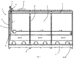
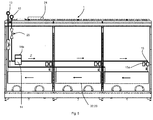
- Fig. 1 shows a cooling unit 1, which comprises a space W to be cooled.
- Characteristic of the space W to be cooled is that the space is bounded by a ceiling element 2, a back wall 4 and a floor element 6.
- the ceiling element 2 closes the goods space W to be cooled upwards.
- the bottom element 6 limits the cooling unit 1 downwards, wherein the waste water can be removed from the goods compartment to be cooled via openings in the base element.
- 6 standing elements 8 can be provided on the bottom element, which are adjustable in dependence on the local conditions. In the simplest case, the stand elements 8 as feet, which are designed to be adjustable in height provided.
- the cooling unit 1 shown here in this embodiment further comprises vertical struts 10, which are provided for additional stabilization of the back wall 4 and which also support the ceiling element 2 with.
- these struts 10 serve to receive storage shelves for the food to be cooled (not shown).
- a line section 12 is shown as an example on the outside surface of the ceiling element 2.
- the line section 12 constitutes a part of the cooling medium supply line 16.
- the line section 12 extends in the longitudinal direction of the cooling unit 1 and may comprise at the respective ends E coupling elements (not shown) or also end elements (not shown), depending on whether further cooling units to connect to it are. The supply of the cooling units 1 with cooling medium via the line sections 12th
- a unit is withdrawn via the heat from the space W to be cooled.
- Part of this unit is u.a. a heat exchanger 34 or a heat exchanger 20, a control device 24 and sensor elements (not shown).
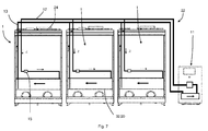
- FIGS. 1 to 10 shown arrows represent the flow or flow direction of the cooling medium within a cooling unit 1 and within the cooling system 22 (not shown).
- An advantage of the local, decentralized pump arrangement 14 is that the delivery pressure of the pump arrangement is such that the pressure loss of the respective line section 12 and 13 and the heat exchanger 34 can be overcome.
- To control the necessary mass flow of the cooling medium sensor elements allow the determination of the demand for the cooling capacity each cooling unit 1.
- An advantageous variant of the requirement determination is the detection of the temperature in the space to be cooled W. Rises z. B. this temperature in the space W to be cooled, the mass flow of the cooling medium is increased by the control unit 14, 15. If the temperature in the room W to be cooled drops, the mass flow of the cooling medium is reduced.
- the heat exchanger 34, 20 is connected to thedemediumabloomtechnisch 18. Characteristic is also that thedemediumzu slaughtertechnisch 16 is connected to the line section 12 and thedemediumabflower Koch 18 with the line section 13 and are integrally formed therewith.
- the cooling medium flows into the cooling unit 1 in the direction of the arrow Z and out of the cooling unit 1 again in the direction of the arrow.
- the cooling unit 1 described here may furthermore, of course, also have known components (not shown here) and can be replaced by the higher-order line sections 12, 13 with the refrigeration circuit and / or the central line network of a refrigeration device, such as a refrigerator. B. be connected to a heat pump.
- thedemediumzumoltechnische 16 is formed in its longitudinal extent within the cooling unit 1 longer than thedemediumabflowertechnisch 18. This is compared to this significantly shortened.
- the ratio of thedemediumzugrintechnisch 16 to the length of thedemediumabflowertechnisch 18 in the ratio of 5: 1 to 1.1: 1 is formed.
- the cooling unit 1 described here can furthermore of course also have known components (not shown here) and is connected by the higher-order line sections 12, 13 to the refrigeration cycle of the heat pump (not shown).
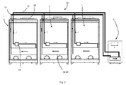
- Each cooling unit 1 comprises an internal cooling medium network and a control device 24, which advantageously controls and / or controls the power of the pump arrangement 14.
- the cooling medium entering the cooling unit 1 first flows through the pump arrangement 14, in order then to be transferred subsequently into the heat exchanger 20. After flowing through the heat exchanger 20, the cooling medium is transported via thedemediumabtextechnisch 18 to the line section 13 and exits from the cooling unit 1 again.
- the cooling unit 1 shown here comprises, in addition to the pump arrangement 14, additional power electronics 14a. Furthermore, shut-off valves 25, which control the cooling medium flow, are also provided within the cooling unit 1.
- Fig. 5 different This is characterized by the fact that additionally throttle bodies 15, z. B. throttle bodies are provided with an associated power electronics 15a.
- the power electronics 15a is advantageously designed as a servomotor.
- the servo motor which is assigned to each throttle member 15, is responsible for adjusting the throttle member 15, for example, to adjust the cooling medium flow.
- Fig. 6 corresponds to the structure Fig. 3 , wherein here, instead of the pump assembly 14, throttle body 15 are arranged in each cooling unit 1. These serve to fine-tune the need.
- cooling system 22 also includes a single pump assembly 14 which is disposed within a cooling unit.
- Fig. 7 a further embodiment with throttle bodies 15 is shown, in which case the pump assembly 14 is disposed within the heat pump. This is also advantageous to keep the pump assembly ice-free and / or condensate-free.
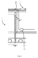
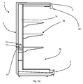
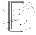
- Fig. 8a-c shows a schematic side view of a cooling unit 1, wherein the same reference numerals as in Fig. 1 same ingredients and will not be explained again here.
- the bottom element 6 is here trough-shaped in the front region, advantageously the back wall 4 opposite, formed.
- the depression serves as a condensate collection trap and / or as a refrigerant collection trap during maintenance work.
- cooling unit 1 still shelves 26 and an outlet region 30, from which the cold air flow exits like a curtain and the gravity falls down.
- Fig. 8b . c show further embodiments of the cooling unit 1, wherein the cooling medium lines 12 and 13 are integral parts of the cooling space. This means that the line sections 12 and 13 are introduced into the insulation or the insulation of the rear wall 4 or the ceiling element 2.
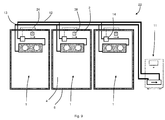
- Fig. 9 finally shows yet another embodiment.
- the cooling units 1 are formed as cooling chambers.
- the arrangements of the individual components within the cooling chambers are different from the exemplary cooling units listed above.
- Each cooling unit, here each cooling chamber comprises in addition to a pump arrangement 14 and a control device 24 additionally at least one sensor element 38, advantageously for temperature detection.
- the one shown here Cooling system 22 is connected via the pipeline network to a heat pump 11.
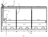
- Fig. 10 a further advantageous embodiment of the cooling unit 1 is shown.
- the cooling unit 1 is here, as in the upper figures, designed as a cooling unit module, which can be arranged individually and / or in combination with further cooling module units 1. In the latter case, several cooling units 1 form components of a cooling system 22.
- the insulation unit 36 is firmly connected to the ceiling element 2.
- the pump assembly 14 and / or throttle body 15 is arranged within the insulation unit 36.
- the pump assembly 14 and / or throttle body 15 is arranged in the direction of flow of the cooling medium of the pump assembly 14 and / or the throttle body 15 .
- a check valve 25 upstream. This regulates the flow of the cooling medium and can completely prevent it, for example during repairs or transport.
- Another shut-off valve 25 is also arranged in the insulation unit 36 in Auströmraum the cooling medium.
- the connection of insulation unit 36 with cooling unit 1 in that both components have a common opening 42.
- the opening 42 may be formed as a connection between the internal volume of the insulation unit 36 and the interior of the cooling unit 1. In this case, possible condensate can flow directly out of the insulation unit 36, over its inclined bottom surface 44 and removed via the cooling unit 1.
- the condensate collecting channel and / or the inclined bottom region 44 may be formed of a further material, for example of a water-resistant and / or water-repellent organic and / or inorganic coating, for example of at least one polymer, at least one block copolymer, at least one surfactant, at least one sol or at least one sol-gel composition and / or a mixture thereof.
- the organic coating may comprise at least one halogen, for example fluorine.
- the at least one coating material is hydrophobic, advantageously formed superhydrophobic, so that on the one hand a large contact angle of greater and / or equal 90 ° spans and consequently only small wetting surfaces between the condensate and coating material are formed.
Landscapes
- Engineering & Computer Science (AREA)
- Physics & Mathematics (AREA)
- Thermal Sciences (AREA)
- General Engineering & Computer Science (AREA)
- Mechanical Engineering (AREA)
- Combustion & Propulsion (AREA)
- Chemical & Material Sciences (AREA)
- Devices That Are Associated With Refrigeration Equipment (AREA)
- Air Conditioning Control Device (AREA)
- Fluid-Pressure Circuits (AREA)
- Beans For Foods Or Fodder (AREA)
- Other Air-Conditioning Systems (AREA)
- Cold Air Circulating Systems And Constructional Details In Refrigerators (AREA)
Priority Applications (1)
| Application Number | Priority Date | Filing Date | Title |
|---|---|---|---|
| PL16155198T PL3076106T3 (pl) | 2015-03-30 | 2016-02-11 | Jednostka chłodząca |
Applications Claiming Priority (1)
| Application Number | Priority Date | Filing Date | Title |
|---|---|---|---|
| DE102015104901 | 2015-03-30 |
Publications (3)
| Publication Number | Publication Date |
|---|---|
| EP3076106A2 true EP3076106A2 (fr) | 2016-10-05 |
| EP3076106A3 EP3076106A3 (fr) | 2016-11-23 |
| EP3076106B1 EP3076106B1 (fr) | 2020-12-02 |
Family
ID=55359423
Family Applications (1)
| Application Number | Title | Priority Date | Filing Date |
|---|---|---|---|
| EP16155198.1A Not-in-force EP3076106B1 (fr) | 2015-03-30 | 2016-02-11 | Unite de refroidissement |
Country Status (6)
| Country | Link |
|---|---|
| EP (1) | EP3076106B1 (fr) |
| DE (5) | DE102015117850A1 (fr) |
| DK (5) | DK3076106T3 (fr) |
| ES (4) | ES2726876T3 (fr) |
| PL (1) | PL3076106T3 (fr) |
| PT (1) | PT3076110T (fr) |
Cited By (2)
| Publication number | Priority date | Publication date | Assignee | Title |
|---|---|---|---|---|
| WO2019072924A1 (fr) * | 2017-10-12 | 2019-04-18 | Viessmann Werke Gmbh & Co. Kg | Meuble de refroidissement doté d'une régulation hydraulique intégrée et système de refroidissement |
| EP3587968A1 (fr) | 2018-06-27 | 2020-01-01 | Viessmann Werke GmbH & Co KG | Système fluidique |
Families Citing this family (2)
| Publication number | Priority date | Publication date | Assignee | Title |
|---|---|---|---|---|
| DE102022101450A1 (de) | 2022-01-21 | 2023-07-27 | Dürr Systems Ag | Wärmeversorgungsnetz für eine prozessanlage und verfahren zum betreiben eines solchen wärmeversorgungsnetzes |
| DE102024112107B4 (de) * | 2024-04-30 | 2026-02-12 | Fraunhofer-Gesellschaft zur Förderung der angewandten Forschung eingetragener Verein | Verfahren zum Betrieb eines elektrisch betriebenen Prozessraums eines Industriesystems, Industriesystem, Computerprogrammprodukt und computerlesbares Speichermedium |
Family Cites Families (24)
| Publication number | Priority date | Publication date | Assignee | Title |
|---|---|---|---|---|
| DE1807916C3 (de) | 1968-11-08 | 1973-12-13 | Aurora-Fahrzeugheizungen Konrad G. Schulz Kg, 6933 Mudau | Vorrichtung zur Reglung von warmetechnischen, in sich geschlosse nen Kreislaufen |
| JPS563379U (fr) * | 1979-06-19 | 1981-01-13 | ||
| JPH063338B2 (ja) * | 1989-12-07 | 1994-01-12 | サンデン株式会社 | 冷凍・冷蔵オープンショーケースを備えた店舗構造 |
| US5944089A (en) | 1994-05-26 | 1999-08-31 | Roland; Russel Anthony | Thermal storage systems for buildings |
| JPH08189758A (ja) * | 1995-01-09 | 1996-07-23 | Hitachi Ltd | 冷凍冷蔵装置のコントローラ |
| JP3695888B2 (ja) * | 1997-03-31 | 2005-09-14 | 三洋電機株式会社 | ブラインを用いた冷却システム |
| ATE221219T1 (de) | 1997-04-14 | 2002-08-15 | Siemens Building Tech Ag | Steuereinrichtung für eine heizungs-oder kälteanlage mit einem pufferspeicher |
| JPH11183012A (ja) | 1997-12-22 | 1999-07-06 | Shinsei Reizou Kogyo Kk | オープンショーケース、冷蔵庫等の冷蔵方法 |
| US6779358B2 (en) * | 1997-12-30 | 2004-08-24 | International Water Makers, Inc. | Water collection and dispensing machine |
| DE10025525A1 (de) | 2000-05-11 | 2001-11-22 | Eugen Gerster | Wärmetransportsystem |
| CN100353128C (zh) * | 2001-06-26 | 2007-12-05 | 大金工业株式会社 | 冷冻装置 |
| US6578376B2 (en) * | 2001-11-02 | 2003-06-17 | Matt Alvin Thurman | Refrigeration apparatus and associated methods |
| JP4253537B2 (ja) * | 2003-07-14 | 2009-04-15 | 三菱電機株式会社 | 冷凍空調装置 |
| GB2405688A (en) * | 2003-09-05 | 2005-03-09 | Applied Design & Eng Ltd | Refrigerator |
| DE102004046791A1 (de) | 2004-09-27 | 2006-04-06 | Kermi Gmbh | Schnittstelleneinheit zum Zuführen und Abführen eines Kühlmediums zu und von einer Verbrauchereinheit |
| JP2006138552A (ja) * | 2004-11-12 | 2006-06-01 | Sharp Corp | 冷却庫 |
| JP2007046810A (ja) * | 2005-08-08 | 2007-02-22 | Sanden Corp | ブライン式冷却システム |
| JP2007107731A (ja) * | 2005-10-11 | 2007-04-26 | Sanden Corp | 冷却システム |
| US20110271701A1 (en) * | 2010-05-05 | 2011-11-10 | Hill Phoenix, Inc. | Refrigerated case with embedded contact cooling structure |
| DE102011000690A1 (de) * | 2011-02-14 | 2012-08-16 | Kmw Kühlmöbelwerk Limburg Gmbh | Kühlmöbel für ein zentrales Kälteversorgungssystem |
| DE102012018021A1 (de) | 2012-09-12 | 2014-03-13 | Liebherr-Hausgeräte Lienz Gmbh | Kühl- und/oder Gefriergerät |
| DE202012103715U1 (de) | 2012-09-27 | 2012-12-14 | Viessmann Kältetechnik AG | Einrichtung zur Bestimmung des Ladezustands eines thermischen Speichers |
| DE102012023848A1 (de) | 2012-12-05 | 2014-06-05 | iEXERGY GmbH | Verfahren und Vorrichtung zur Vereinfachung des hydraulischen Abgleichs von fluiddurchströmten Leitungsnetzen |
| DE102013004106A1 (de) | 2013-03-11 | 2014-09-11 | Wilo Se | Heizungssystem und Nachrüstkit zur Verbesserung der Wärmeabgabe von hydraulisch unterversorgten Verbrauchern |
-
2015
- 2015-10-20 DE DE102015117850.8A patent/DE102015117850A1/de not_active Withdrawn
- 2015-10-20 DE DE102015117848.6A patent/DE102015117848A1/de not_active Withdrawn
- 2015-10-20 DE DE102015117851.6A patent/DE102015117851B4/de not_active Expired - Fee Related
- 2015-10-21 DE DE102015117948.2A patent/DE102015117948B4/de not_active Expired - Fee Related
- 2015-11-10 DE DE102015119362.0A patent/DE102015119362A1/de not_active Withdrawn
-
2016
- 2016-02-11 EP EP16155198.1A patent/EP3076106B1/fr not_active Not-in-force
- 2016-02-11 DK DK16155198.1T patent/DK3076106T3/da active
- 2016-02-11 DK DK16155272.4T patent/DK3076110T3/da active
- 2016-02-11 PL PL16155198T patent/PL3076106T3/pl unknown
- 2016-02-11 DK DK16155249.2T patent/DK3076109T3/da active
- 2016-02-11 ES ES16155272T patent/ES2726876T3/es active Active
- 2016-02-11 DK DK16155294.8T patent/DK3076111T3/da active
- 2016-02-11 ES ES16155198T patent/ES2856854T3/es active Active
- 2016-02-11 DK DK16155221.1T patent/DK3076108T3/da active
- 2016-02-11 ES ES16155294T patent/ES2856411T3/es active Active
- 2016-02-11 ES ES16155221T patent/ES2841347T3/es active Active
- 2016-02-11 PT PT16155272T patent/PT3076110T/pt unknown
Non-Patent Citations (1)
| Title |
|---|
| None |
Cited By (5)
| Publication number | Priority date | Publication date | Assignee | Title |
|---|---|---|---|---|
| WO2019072924A1 (fr) * | 2017-10-12 | 2019-04-18 | Viessmann Werke Gmbh & Co. Kg | Meuble de refroidissement doté d'une régulation hydraulique intégrée et système de refroidissement |
| AU2018348735B2 (en) * | 2017-10-12 | 2022-01-06 | Viessmann Refrigeration Solutions Gmbh | Refrigerated cabinet with built-in hydraulic regulation, and refrigerating system |
| EP3587968A1 (fr) | 2018-06-27 | 2020-01-01 | Viessmann Werke GmbH & Co KG | Système fluidique |
| DE102018115423A1 (de) | 2018-06-27 | 2020-01-02 | Viessmann Werke Gmbh & Co Kg | Fluidsystem |
| DE102018115423B4 (de) | 2018-06-27 | 2021-10-21 | Viessmann Werke Gmbh & Co Kg | Fluidsystem |
Also Published As
| Publication number | Publication date |
|---|---|
| DK3076108T3 (da) | 2021-02-01 |
| ES2726876T3 (es) | 2019-10-10 |
| EP3076106B1 (fr) | 2020-12-02 |
| DK3076106T3 (da) | 2021-03-01 |
| ES2856854T3 (es) | 2021-09-28 |
| DE102015117948B4 (de) | 2023-06-29 |
| PL3076106T3 (pl) | 2021-08-23 |
| DE102015117948A1 (de) | 2016-10-06 |
| PT3076110T (pt) | 2019-06-06 |
| DK3076109T3 (da) | 2021-10-04 |
| ES2856411T3 (es) | 2021-09-27 |
| DE102015117848A1 (de) | 2016-10-06 |
| DE102015117850A1 (de) | 2016-10-06 |
| DE102015117851A1 (de) | 2016-10-06 |
| DK3076110T3 (da) | 2019-06-03 |
| DE102015117851B4 (de) | 2022-07-28 |
| DE102015119362A1 (de) | 2016-10-06 |
| ES2841347T3 (es) | 2021-07-08 |
| EP3076106A3 (fr) | 2016-11-23 |
| DK3076111T3 (da) | 2021-03-08 |
Similar Documents
| Publication | Publication Date | Title |
|---|---|---|
| EP2342511B1 (fr) | Réfrigérateur domestique, ainsi que système modulaire de réfrigérateur domestique | |
| EP3431891B1 (fr) | Humidificateur et procédé de conditionnement d'air | |
| EP3076106B1 (fr) | Unite de refroidissement | |
| CH402906A (de) | Kühltruhe | |
| EP3023705B1 (fr) | Site de production comprenant un bâtiment fermé et une installation de ventilation et procédé de climatisation d'un tel bâtiment | |
| DE202011110116U1 (de) | Kühlmöbel mit einem mittels kalter Außenluft kühlbaren Kühlraum | |
| EP3097360B1 (fr) | Installation frigorifique comprenant un échangeur de chaleur refroidi par air | |
| DE102011110039A1 (de) | Belüfttungsanlage mit kühlbarem PCM-Wärmetauscher und Verfahren zum Betreiben der Belüftungsanlage | |
| DE102015118475A1 (de) | Verfahren zum Betrieb einer dezentralen Vorrichtung zur kontrollierten Wohnraumlüftung sowie verfahrensgemäß ausgebildete Wohnraumlüftungsvorrichtung | |
| EP2378227A1 (fr) | Réfrigérateur | |
| DE102008026158B3 (de) | Klimatisierungssystem für kleine Behältnisse | |
| EP3370491A1 (fr) | Système de refroidissement destiné au refroidissement d'une armoire de serveur disposée dans un espace | |
| EP3608607B1 (fr) | Appareil frigorifique doté d'au moins deux évaporateurs | |
| DE102010017919A1 (de) | Kühl- und/oder Gefriergerät | |
| WO2018001732A1 (fr) | Appareil de froid | |
| EP1672294A2 (fr) | Système de conditionnement d'air | |
| AT509084B1 (de) | Kühlvorrichtung | |
| DE102006061155A1 (de) | Kältegerät | |
| DE1009203B (de) | Luftentfeuchter bzw. Klein-Klimageraet | |
| DE102008059854A1 (de) | Inkubations- und Trockenlagervorrichtung | |
| DE102011117930A1 (de) | Kühl- und/oder Gefriergerät | |
| EP2776768B1 (fr) | Appareil frigorifique | |
| DE2153175C3 (de) | Anlage zum Temperieren und Entfeuchten eines Luftstromes zur Klimatisierung von Räumen | |
| DE102018202008A1 (de) | Kombinationskältegerät | |
| DE102012003935A1 (de) | Kühl- und/oder Gefriergerät |
Legal Events
| Date | Code | Title | Description |
|---|---|---|---|
| PUAI | Public reference made under article 153(3) epc to a published international application that has entered the european phase |
Free format text: ORIGINAL CODE: 0009012 |
|
| AK | Designated contracting states |
Kind code of ref document: A2 Designated state(s): AL AT BE BG CH CY CZ DE DK EE ES FI FR GB GR HR HU IE IS IT LI LT LU LV MC MK MT NL NO PL PT RO RS SE SI SK SM TR |
|
| AX | Request for extension of the european patent |
Extension state: BA ME |
|
| PUAL | Search report despatched |
Free format text: ORIGINAL CODE: 0009013 |
|
| AK | Designated contracting states |
Kind code of ref document: A3 Designated state(s): AL AT BE BG CH CY CZ DE DK EE ES FI FR GB GR HR HU IE IS IT LI LT LU LV MC MK MT NL NO PL PT RO RS SE SI SK SM TR |
|
| AX | Request for extension of the european patent |
Extension state: BA ME |
|
| RIC1 | Information provided on ipc code assigned before grant |
Ipc: A47F 3/04 20060101ALI20161018BHEP Ipc: F25D 29/00 20060101ALI20161018BHEP Ipc: F25D 21/04 20060101ALI20161018BHEP Ipc: F25D 13/00 20060101AFI20161018BHEP |
|
| STAA | Information on the status of an ep patent application or granted ep patent |
Free format text: STATUS: REQUEST FOR EXAMINATION WAS MADE |
|
| 17P | Request for examination filed |
Effective date: 20170519 |
|
| RBV | Designated contracting states (corrected) |
Designated state(s): AL AT BE BG CH CY CZ DE DK EE ES FI FR GB GR HR HU IE IS IT LI LT LU LV MC MK MT NL NO PL PT RO RS SE SI SK SM TR |
|
| STAA | Information on the status of an ep patent application or granted ep patent |
Free format text: STATUS: EXAMINATION IS IN PROGRESS |
|
| 17Q | First examination report despatched |
Effective date: 20190916 |
|
| GRAP | Despatch of communication of intention to grant a patent |
Free format text: ORIGINAL CODE: EPIDOSNIGR1 |
|
| STAA | Information on the status of an ep patent application or granted ep patent |
Free format text: STATUS: GRANT OF PATENT IS INTENDED |
|
| INTG | Intention to grant announced |
Effective date: 20200623 |
|
| GRAS | Grant fee paid |
Free format text: ORIGINAL CODE: EPIDOSNIGR3 |
|
| GRAJ | Information related to disapproval of communication of intention to grant by the applicant or resumption of examination proceedings by the epo deleted |
Free format text: ORIGINAL CODE: EPIDOSDIGR1 |
|
| GRAL | Information related to payment of fee for publishing/printing deleted |
Free format text: ORIGINAL CODE: EPIDOSDIGR3 |
|
| STAA | Information on the status of an ep patent application or granted ep patent |
Free format text: STATUS: EXAMINATION IS IN PROGRESS |
|
| INTC | Intention to grant announced (deleted) | ||
| GRAP | Despatch of communication of intention to grant a patent |
Free format text: ORIGINAL CODE: EPIDOSNIGR1 |
|
| STAA | Information on the status of an ep patent application or granted ep patent |
Free format text: STATUS: GRANT OF PATENT IS INTENDED |
|
| INTG | Intention to grant announced |
Effective date: 20201002 |
|
| RAP1 | Party data changed (applicant data changed or rights of an application transferred) |
Owner name: VIESSMANN REFRIGERATION SOLUTIONS GMBH |
|
| GRAA | (expected) grant |
Free format text: ORIGINAL CODE: 0009210 |
|
| STAA | Information on the status of an ep patent application or granted ep patent |
Free format text: STATUS: THE PATENT HAS BEEN GRANTED |
|
| AK | Designated contracting states |
Kind code of ref document: B1 Designated state(s): AL AT BE BG CH CY CZ DE DK EE ES FI FR GB GR HR HU IE IS IT LI LT LU LV MC MK MT NL NO PL PT RO RS SE SI SK SM TR |
|
| REG | Reference to a national code |
Ref country code: GB Ref legal event code: FG4D Free format text: NOT ENGLISH |
|
| REG | Reference to a national code |
Ref country code: AT Ref legal event code: REF Ref document number: 1341378 Country of ref document: AT Kind code of ref document: T Effective date: 20201215 Ref country code: CH Ref legal event code: EP |
|
| REG | Reference to a national code |
Ref country code: IE Ref legal event code: FG4D Free format text: LANGUAGE OF EP DOCUMENT: GERMAN |
|
| REG | Reference to a national code |
Ref country code: DE Ref legal event code: R096 Ref document number: 502016011816 Country of ref document: DE |
|
| REG | Reference to a national code |
Ref country code: DK Ref legal event code: T3 Effective date: 20210225 |
|
| REG | Reference to a national code |
Ref country code: FI Ref legal event code: FGE |
|
| REG | Reference to a national code |
Ref country code: SE Ref legal event code: TRGR |
|
| REG | Reference to a national code |
Ref country code: NL Ref legal event code: FP |
|
| PG25 | Lapsed in a contracting state [announced via postgrant information from national office to epo] |
Ref country code: RS Free format text: LAPSE BECAUSE OF FAILURE TO SUBMIT A TRANSLATION OF THE DESCRIPTION OR TO PAY THE FEE WITHIN THE PRESCRIBED TIME-LIMIT Effective date: 20201202 Ref country code: GR Free format text: LAPSE BECAUSE OF FAILURE TO SUBMIT A TRANSLATION OF THE DESCRIPTION OR TO PAY THE FEE WITHIN THE PRESCRIBED TIME-LIMIT Effective date: 20210303 |
|
| REG | Reference to a national code |
Ref country code: NO Ref legal event code: T2 Effective date: 20201202 |
|
| PG25 | Lapsed in a contracting state [announced via postgrant information from national office to epo] |
Ref country code: BG Free format text: LAPSE BECAUSE OF FAILURE TO SUBMIT A TRANSLATION OF THE DESCRIPTION OR TO PAY THE FEE WITHIN THE PRESCRIBED TIME-LIMIT Effective date: 20210302 Ref country code: LV Free format text: LAPSE BECAUSE OF FAILURE TO SUBMIT A TRANSLATION OF THE DESCRIPTION OR TO PAY THE FEE WITHIN THE PRESCRIBED TIME-LIMIT Effective date: 20201202 |
|
| PG25 | Lapsed in a contracting state [announced via postgrant information from national office to epo] |
Ref country code: HR Free format text: LAPSE BECAUSE OF FAILURE TO SUBMIT A TRANSLATION OF THE DESCRIPTION OR TO PAY THE FEE WITHIN THE PRESCRIBED TIME-LIMIT Effective date: 20201202 |
|
| REG | Reference to a national code |
Ref country code: LT Ref legal event code: MG9D |
|
| PG25 | Lapsed in a contracting state [announced via postgrant information from national office to epo] |
Ref country code: PT Free format text: LAPSE BECAUSE OF FAILURE TO SUBMIT A TRANSLATION OF THE DESCRIPTION OR TO PAY THE FEE WITHIN THE PRESCRIBED TIME-LIMIT Effective date: 20210405 Ref country code: RO Free format text: LAPSE BECAUSE OF FAILURE TO SUBMIT A TRANSLATION OF THE DESCRIPTION OR TO PAY THE FEE WITHIN THE PRESCRIBED TIME-LIMIT Effective date: 20201202 Ref country code: SK Free format text: LAPSE BECAUSE OF FAILURE TO SUBMIT A TRANSLATION OF THE DESCRIPTION OR TO PAY THE FEE WITHIN THE PRESCRIBED TIME-LIMIT Effective date: 20201202 Ref country code: EE Free format text: LAPSE BECAUSE OF FAILURE TO SUBMIT A TRANSLATION OF THE DESCRIPTION OR TO PAY THE FEE WITHIN THE PRESCRIBED TIME-LIMIT Effective date: 20201202 Ref country code: CZ Free format text: LAPSE BECAUSE OF FAILURE TO SUBMIT A TRANSLATION OF THE DESCRIPTION OR TO PAY THE FEE WITHIN THE PRESCRIBED TIME-LIMIT Effective date: 20201202 Ref country code: SM Free format text: LAPSE BECAUSE OF FAILURE TO SUBMIT A TRANSLATION OF THE DESCRIPTION OR TO PAY THE FEE WITHIN THE PRESCRIBED TIME-LIMIT Effective date: 20201202 Ref country code: LT Free format text: LAPSE BECAUSE OF FAILURE TO SUBMIT A TRANSLATION OF THE DESCRIPTION OR TO PAY THE FEE WITHIN THE PRESCRIBED TIME-LIMIT Effective date: 20201202 |
|
| REG | Reference to a national code |
Ref country code: DE Ref legal event code: R097 Ref document number: 502016011816 Country of ref document: DE |
|
| REG | Reference to a national code |
Ref country code: ES Ref legal event code: FG2A Ref document number: 2856854 Country of ref document: ES Kind code of ref document: T3 Effective date: 20210928 |
|
| PG25 | Lapsed in a contracting state [announced via postgrant information from national office to epo] |
Ref country code: MC Free format text: LAPSE BECAUSE OF FAILURE TO SUBMIT A TRANSLATION OF THE DESCRIPTION OR TO PAY THE FEE WITHIN THE PRESCRIBED TIME-LIMIT Effective date: 20201202 Ref country code: IS Free format text: LAPSE BECAUSE OF FAILURE TO SUBMIT A TRANSLATION OF THE DESCRIPTION OR TO PAY THE FEE WITHIN THE PRESCRIBED TIME-LIMIT Effective date: 20210402 |
|
| PLBE | No opposition filed within time limit |
Free format text: ORIGINAL CODE: 0009261 |
|
| STAA | Information on the status of an ep patent application or granted ep patent |
Free format text: STATUS: NO OPPOSITION FILED WITHIN TIME LIMIT |
|
| PG25 | Lapsed in a contracting state [announced via postgrant information from national office to epo] |
Ref country code: AL Free format text: LAPSE BECAUSE OF FAILURE TO SUBMIT A TRANSLATION OF THE DESCRIPTION OR TO PAY THE FEE WITHIN THE PRESCRIBED TIME-LIMIT Effective date: 20201202 Ref country code: LU Free format text: LAPSE BECAUSE OF NON-PAYMENT OF DUE FEES Effective date: 20210211 |
|
| 26N | No opposition filed |
Effective date: 20210903 |
|
| PG25 | Lapsed in a contracting state [announced via postgrant information from national office to epo] |
Ref country code: SI Free format text: LAPSE BECAUSE OF FAILURE TO SUBMIT A TRANSLATION OF THE DESCRIPTION OR TO PAY THE FEE WITHIN THE PRESCRIBED TIME-LIMIT Effective date: 20201202 |
|
| PG25 | Lapsed in a contracting state [announced via postgrant information from national office to epo] |
Ref country code: IE Free format text: LAPSE BECAUSE OF NON-PAYMENT OF DUE FEES Effective date: 20210211 |
|
| PGFP | Annual fee paid to national office [announced via postgrant information from national office to epo] |
Ref country code: GB Payment date: 20220221 Year of fee payment: 7 Ref country code: DK Payment date: 20220221 Year of fee payment: 7 Ref country code: CH Payment date: 20220217 Year of fee payment: 7 |
|
| PG25 | Lapsed in a contracting state [announced via postgrant information from national office to epo] |
Ref country code: IS Free format text: LAPSE BECAUSE OF FAILURE TO SUBMIT A TRANSLATION OF THE DESCRIPTION OR TO PAY THE FEE WITHIN THE PRESCRIBED TIME-LIMIT Effective date: 20210402 |
|
| PGFP | Annual fee paid to national office [announced via postgrant information from national office to epo] |
Ref country code: SE Payment date: 20220221 Year of fee payment: 7 Ref country code: NO Payment date: 20220222 Year of fee payment: 7 Ref country code: NL Payment date: 20220222 Year of fee payment: 7 Ref country code: FR Payment date: 20220219 Year of fee payment: 7 Ref country code: ES Payment date: 20220301 Year of fee payment: 7 Ref country code: BE Payment date: 20220218 Year of fee payment: 7 |
|
| PG25 | Lapsed in a contracting state [announced via postgrant information from national office to epo] |
Ref country code: HU Free format text: LAPSE BECAUSE OF FAILURE TO SUBMIT A TRANSLATION OF THE DESCRIPTION OR TO PAY THE FEE WITHIN THE PRESCRIBED TIME-LIMIT; INVALID AB INITIO Effective date: 20160211 |
|
| P01 | Opt-out of the competence of the unified patent court (upc) registered |
Effective date: 20230512 |
|
| PG25 | Lapsed in a contracting state [announced via postgrant information from national office to epo] |
Ref country code: CY Free format text: LAPSE BECAUSE OF FAILURE TO SUBMIT A TRANSLATION OF THE DESCRIPTION OR TO PAY THE FEE WITHIN THE PRESCRIBED TIME-LIMIT Effective date: 20201202 |
|
| REG | Reference to a national code |
Ref country code: NO Ref legal event code: MMEP Ref country code: DK Ref legal event code: EBP Effective date: 20230228 |
|
| REG | Reference to a national code |
Ref country code: CH Ref legal event code: PL |
|
| REG | Reference to a national code |
Ref country code: SE Ref legal event code: EUG |
|
| REG | Reference to a national code |
Ref country code: NL Ref legal event code: MM Effective date: 20230301 |
|
| REG | Reference to a national code |
Ref country code: BE Ref legal event code: MM Effective date: 20230228 |
|
| GBPC | Gb: european patent ceased through non-payment of renewal fee |
Effective date: 20230211 |
|
| PG25 | Lapsed in a contracting state [announced via postgrant information from national office to epo] |
Ref country code: SE Free format text: LAPSE BECAUSE OF NON-PAYMENT OF DUE FEES Effective date: 20230212 Ref country code: NO Free format text: LAPSE BECAUSE OF NON-PAYMENT OF DUE FEES Effective date: 20230228 Ref country code: LI Free format text: LAPSE BECAUSE OF NON-PAYMENT OF DUE FEES Effective date: 20230228 Ref country code: CH Free format text: LAPSE BECAUSE OF NON-PAYMENT OF DUE FEES Effective date: 20230228 |
|
| PG25 | Lapsed in a contracting state [announced via postgrant information from national office to epo] |
Ref country code: NL Free format text: LAPSE BECAUSE OF NON-PAYMENT OF DUE FEES Effective date: 20230301 |
|
| PG25 | Lapsed in a contracting state [announced via postgrant information from national office to epo] |
Ref country code: GB Free format text: LAPSE BECAUSE OF NON-PAYMENT OF DUE FEES Effective date: 20230211 |
|
| PG25 | Lapsed in a contracting state [announced via postgrant information from national office to epo] |
Ref country code: GB Free format text: LAPSE BECAUSE OF NON-PAYMENT OF DUE FEES Effective date: 20230211 Ref country code: FR Free format text: LAPSE BECAUSE OF NON-PAYMENT OF DUE FEES Effective date: 20230228 Ref country code: DK Free format text: LAPSE BECAUSE OF NON-PAYMENT OF DUE FEES Effective date: 20230228 |
|
| PG25 | Lapsed in a contracting state [announced via postgrant information from national office to epo] |
Ref country code: BE Free format text: LAPSE BECAUSE OF NON-PAYMENT OF DUE FEES Effective date: 20230228 |
|
| REG | Reference to a national code |
Ref country code: ES Ref legal event code: FD2A Effective date: 20240405 |
|
| PG25 | Lapsed in a contracting state [announced via postgrant information from national office to epo] |
Ref country code: ES Free format text: LAPSE BECAUSE OF NON-PAYMENT OF DUE FEES Effective date: 20230212 |
|
| PGFP | Annual fee paid to national office [announced via postgrant information from national office to epo] |
Ref country code: AT Payment date: 20240226 Year of fee payment: 9 |
|
| PG25 | Lapsed in a contracting state [announced via postgrant information from national office to epo] |
Ref country code: MK Free format text: LAPSE BECAUSE OF FAILURE TO SUBMIT A TRANSLATION OF THE DESCRIPTION OR TO PAY THE FEE WITHIN THE PRESCRIBED TIME-LIMIT Effective date: 20201202 Ref country code: ES Free format text: LAPSE BECAUSE OF NON-PAYMENT OF DUE FEES Effective date: 20230212 |
|
| PGFP | Annual fee paid to national office [announced via postgrant information from national office to epo] |
Ref country code: FI Payment date: 20240220 Year of fee payment: 9 Ref country code: DE Payment date: 20231129 Year of fee payment: 9 |
|
| PGFP | Annual fee paid to national office [announced via postgrant information from national office to epo] |
Ref country code: PL Payment date: 20240129 Year of fee payment: 9 Ref country code: IT Payment date: 20240227 Year of fee payment: 9 |
|
| PG25 | Lapsed in a contracting state [announced via postgrant information from national office to epo] |
Ref country code: MT Free format text: LAPSE BECAUSE OF FAILURE TO SUBMIT A TRANSLATION OF THE DESCRIPTION OR TO PAY THE FEE WITHIN THE PRESCRIBED TIME-LIMIT Effective date: 20201202 |
|
| REG | Reference to a national code |
Ref country code: DE Ref legal event code: R119 Ref document number: 502016011816 Country of ref document: DE |
|
| PG25 | Lapsed in a contracting state [announced via postgrant information from national office to epo] |
Ref country code: FI Free format text: LAPSE BECAUSE OF NON-PAYMENT OF DUE FEES Effective date: 20250211 |
|
| REG | Reference to a national code |
Ref country code: AT Ref legal event code: MM01 Ref document number: 1341378 Country of ref document: AT Kind code of ref document: T Effective date: 20250211 |
|
| PG25 | Lapsed in a contracting state [announced via postgrant information from national office to epo] |
Ref country code: AT Free format text: LAPSE BECAUSE OF NON-PAYMENT OF DUE FEES Effective date: 20250211 |
|
| PG25 | Lapsed in a contracting state [announced via postgrant information from national office to epo] |
Ref country code: TR Free format text: LAPSE BECAUSE OF FAILURE TO SUBMIT A TRANSLATION OF THE DESCRIPTION OR TO PAY THE FEE WITHIN THE PRESCRIBED TIME-LIMIT Effective date: 20201202 |
|
| PG25 | Lapsed in a contracting state [announced via postgrant information from national office to epo] |
Ref country code: DE Free format text: LAPSE BECAUSE OF NON-PAYMENT OF DUE FEES Effective date: 20250902 |
|
| PG25 | Lapsed in a contracting state [announced via postgrant information from national office to epo] |
Ref country code: IT Free format text: LAPSE BECAUSE OF NON-PAYMENT OF DUE FEES Effective date: 20250211 |
|
| PG25 | Lapsed in a contracting state [announced via postgrant information from national office to epo] |
Ref country code: PL Free format text: LAPSE BECAUSE OF NON-PAYMENT OF DUE FEES Effective date: 20250211 |