EP3587968A1 - Système fluidique - Google Patents
Système fluidique Download PDFInfo
- Publication number
- EP3587968A1 EP3587968A1 EP19182186.7A EP19182186A EP3587968A1 EP 3587968 A1 EP3587968 A1 EP 3587968A1 EP 19182186 A EP19182186 A EP 19182186A EP 3587968 A1 EP3587968 A1 EP 3587968A1
- Authority
- EP
- European Patent Office
- Prior art keywords
- fluid
- circuit
- main distribution
- distribution circuit
- fluid system
- Prior art date
- Legal status (The legal status is an assumption and is not a legal conclusion. Google has not performed a legal analysis and makes no representation as to the accuracy of the status listed.)
- Granted
Links
Images

Classifications
-
- F—MECHANICAL ENGINEERING; LIGHTING; HEATING; WEAPONS; BLASTING
- F24—HEATING; RANGES; VENTILATING
- F24D—DOMESTIC- OR SPACE-HEATING SYSTEMS, e.g. CENTRAL HEATING SYSTEMS; DOMESTIC HOT-WATER SUPPLY SYSTEMS; ELEMENTS OR COMPONENTS THEREFOR
- F24D3/00—Hot-water central heating systems
- F24D3/10—Feed-line arrangements, e.g. providing for heat-accumulator tanks, expansion tanks ; Hydraulic components of a central heating system
- F24D3/1091—Mixing cylinders
-
- F—MECHANICAL ENGINEERING; LIGHTING; HEATING; WEAPONS; BLASTING
- F24—HEATING; RANGES; VENTILATING
- F24D—DOMESTIC- OR SPACE-HEATING SYSTEMS, e.g. CENTRAL HEATING SYSTEMS; DOMESTIC HOT-WATER SUPPLY SYSTEMS; ELEMENTS OR COMPONENTS THEREFOR
- F24D7/00—Central heating systems employing heat-transfer fluids not covered by groups F24D1/00 - F24D5/00, e.g. oil, salt or gas
-
- F—MECHANICAL ENGINEERING; LIGHTING; HEATING; WEAPONS; BLASTING
- F25—REFRIGERATION OR COOLING; COMBINED HEATING AND REFRIGERATION SYSTEMS; HEAT PUMP SYSTEMS; MANUFACTURE OR STORAGE OF ICE; LIQUEFACTION SOLIDIFICATION OF GASES
- F25D—REFRIGERATORS; COLD ROOMS; ICE-BOXES; COOLING OR FREEZING APPARATUS NOT OTHERWISE PROVIDED FOR
- F25D17/00—Arrangements for circulating cooling fluids; Arrangements for circulating gas, e.g. air, within refrigerated spaces
- F25D17/02—Arrangements for circulating cooling fluids; Arrangements for circulating gas, e.g. air, within refrigerated spaces for circulating liquids, e.g. brine
-
- Y—GENERAL TAGGING OF NEW TECHNOLOGICAL DEVELOPMENTS; GENERAL TAGGING OF CROSS-SECTIONAL TECHNOLOGIES SPANNING OVER SEVERAL SECTIONS OF THE IPC; TECHNICAL SUBJECTS COVERED BY FORMER USPC CROSS-REFERENCE ART COLLECTIONS [XRACs] AND DIGESTS
- Y02—TECHNOLOGIES OR APPLICATIONS FOR MITIGATION OR ADAPTATION AGAINST CLIMATE CHANGE
- Y02B—CLIMATE CHANGE MITIGATION TECHNOLOGIES RELATED TO BUILDINGS, e.g. HOUSING, HOUSE APPLIANCES OR RELATED END-USER APPLICATIONS
- Y02B30/00—Energy efficient heating, ventilation or air conditioning [HVAC]
- Y02B30/70—Efficient control or regulation technologies, e.g. for control of refrigerant flow, motor or heating
Definitions
- a fluid system is described with a main distribution circuit with a flow and a return, in which a fluid for heat transfer is guided, the main distribution circuit being connected to a device for providing an adjustable temperature for the fluid, and with at least two secondary circuits connected to the main distribution circuit ,
- the device for providing an adjustable temperature for the fluid can use a liquid for heat / cold generation, which is conducted in a separate circuit.
- Heating or cooling circuits with a widely branched network with several strings connected in parallel and connected to a main circuit have several disadvantages. On the one hand, the temperature of the fluid for heating or cooling increases or decreases along the length of the lines. On the other hand, there are also pressure drops along the lines. This creates significant problems with hydraulic balancing.
- a fluid for example coolant
- the coolant has to be cooled down significantly further than would actually be necessary. This then compensates for the temperature rise along the lines.
- a supply device for example a valve
- a supply device can be switched off, since otherwise an undesirable formation of ice would occur at the nearby consumer.
- a fluid system with a main distribution circuit with a flow and a return, in which a fluid for heat transfer is guided, the main distribution circuit being connected to a device for providing an adjustable temperature for the fluid, and with at least two secondary circuits connected to the main distribution circuit, the secondary circuits each having at least one consumer and a hydraulic line switch via which the secondary circuits are connected to the main distribution circuit.
- the secondary circuits (strands) are connected in parallel.
- the main distribution group with the secondary groups forms the consumer group.
- the producer group is formed by the facility.
- the individual secondary circuits (strands) of the fluid circuit are therefore decoupled from the main distribution circuit, so that a demand-dependent supply of cold / heat is made possible for the respective strands.
- the device for providing an adjustable temperature for the fluid can be, for example, a refrigerator or a heating device.
- the device can be, for example, a heat pump, a gas or solid fuel combustion device or a solar-powered heating device.
- the fluid in the main distribution circuit and in the secondary circuits can be brine, for example.
- a refrigerant, which is guided in the device on the generator side, for example, is decoupled from the fluid in the main distribution circuit.
- glycol can be used as a coolant in the device.
- the heating or cooling power can be transmitted in various ways to the main distribution circuit and the fluid carried therein.
- the device has a heat exchanger which is provided for transferring the heat provided to the fluid in the fluid circuit or in the main distribution circuit.
- the at least one consumer in the secondary circuits can be, for example, a refrigerated counter, a refrigerated shelf, a freezer, a cold room, a freezer and / or a refrigerator.
- the above list is not exhaustive, so that other cooling devices are also included.
- cooling devices instead of cooling devices, heating devices can also be used as Consumers can be provided in a corresponding heating circuit.
- the waste heat generated for example, during the generation of cold can be used for a separate heating circuit.
- the fluid circuit can therefore be provided in a system that uses both the cold provided and the waste heat generated.
- Heat pumps can preferably be used in such a system.
- the fluid system is suitable, for example, for supermarkets with a large number of cooling devices, the individual cooling devices often being arranged far away from the cooling machine.
- the main distribution circle is therefore very long.
- the requirements for hydraulic balancing for the main distribution circuit are very high.
- the hydraulic balancing via the line switches also ensures that the device for providing an adjustable, changeable temperature can be operated more constantly and is less subject to fluctuations with regard to the temperature to be reached and the volume of fluid to be tempered.
- the temperature to be reached can be changed by a central control.
- the temperature to be reached can be set in accordance with further influences and parameters that have an influence on the fluid system.
- the fluid system can each have a first conveying device which is arranged in the return of the secondary circuits and is connected downstream of the line switch in the fluid flow direction.
- Each strand switch is therefore assigned at least one first conveyor. The hydraulic balancing of each individual secondary circuit can be carried out via these conveyors and the required variable volume flow can be supplied to the respective secondary circuit.
- the first conveying device can in particular be arranged in the return of the secondary circuit in the fluid flow direction before a connection point to the return of the main distribution circuit.
- the main distribution circuit therefore has no central supply device, such as a pump.
- the required amount of fluid is conveyed via the decentralized first delivery devices of the respective sub-districts.
- regulating valves and distributors can be dispensed with.
- the first conveying devices in the secondary circuits which provide the volume flows required for the respective secondary circuit, enable a higher efficiency to be achieved in comparison to a centrally arranged conveying device in the main distribution circuit in part-load operation, thus saving operating costs.
- decentralized first conveying devices Another advantage that is achieved by the decentralized first conveying devices is that the fluid system receives partial redundancy through the decentralized first conveying devices, so that in the event of an accident, damage to goods / failures are restricted to individual secondary groups and the entire system does not have to be taken out of operation or fails.
- the fluid system described herein is particularly suitable for systems that are used in buildings. Due to the increasing number of cold / heat consumers in the buildings (e.g. number of refrigeration points in the food retail trade) or glazing of the cold spots and thus also an increase in the number of consumers per secondary circuit, a regulation is required to provide a stable operating mode for such systems described fluid system is achieved.
- the hydraulic decoupling of the secondary circuits both provides hydraulic balancing for the secondary circuits and improves the flow rate control of the fluid in part-load operation.
- the arrangement of the first conveying devices in the return of the secondary circuit, in particular in the direction of fluid flow in front of a connection point to the return of the main distribution circuit, ensures that there is no intermixing within the line switches and that the main distribution circuit can do entirely without conveying devices.
- the fluid circuit can have a plurality of secondary circuits, each of which is connected to the main distribution circuit via a separate line switch, with each secondary circuit being assigned a consumer group.
- This version offers the possibility of grouping individual consumers together, so that the required fluid requirement is controlled separately via an assigned strand switch.
- the consumer groups can differ by their type, size, position, required fluid temperature and / or their performance.
- consumers that are arranged in a room or section or compartment of a building can be combined.
- freezers can, for example, be combined in a separate secondary circuit and refrigerated shelves in a further, separate secondary circuit.
- cooling devices analogously also heating devices
- the performance can also be decisive for the grouping of consumers in secondary groups.
- consumers are also summarized that have different requirements for the required cooling requirement via the fluid, so that, for example, an overall cooling requirement for the respective secondary circuit is essentially similar to the cooling requirement of parallel secondary circuits. This prevents the line switches from flowing too strongly if, for example, a secondary circuit only has freezing devices that provide a temperature of -20 °, the consumers in a parallel secondary circuit only providing a cooling temperature of 4 ° Celsius.
- the at least one consumer can itself have a second delivery device, via which the second consumer obtains the amount of fluid that is required from the respective secondary circuit as required.
- the requirements for the device for cooling or heating are further reduced.
- heat pumps have to cycle less.
- At least one secondary circuit can have a third conveyor.
- the third delivery device can be provided, for example, for circulating the fluid if the secondary circuit is coupled to a fluid circuit connected to it, for example via a heat transfer device.
- a second fluid circuit can be provided, for example, if the consumer is designed as a deep-freeze room.
- the heat transfer device is required, which brings the temperature provided by the fluid to a level required for the deep-freeze room.
- the cooling liquid, which is guided in the second fluid circuit therefore does not come into direct contact with the fluid of the main distribution circuit.
- the third delivery device is then required in this exemplary embodiment in order to deliver the fluid in the secondary circuit accordingly through the heat transfer device.
- the first delivery device, the second delivery device and / or the third delivery device can be speed-controlled pumps.
- Speed-controlled pumps enable the fluid to be pumped as required.
- a central control for the fluid system can be provided to control the speed-controlled pumps.
- the respective secondary groups can control their associated first conveying devices separately, with a higher-level detection and regulation being additionally provided.
- the main distribution circuit can have a low loss header, via which the main distribution circuit is coupled to the device for providing an adjustable temperature. This provides a first decoupling of the main distribution circuit (consumer side) from the producer side with the device. A first hydraulic balance between the consumer side and the generator side is thus achieved.
- the device for providing an adjustable temperature can have a separate fluid circuit which is thermally directly or indirectly connected to the fluid circuit of the main distribution circuit.
- the separate fluid circuit can also have further devices such as, for example, a feed pump for circulating the fluid carried therein (for example refrigerant).
- the fluid system described herein may further include other components that are not explicitly listed. These include, for example, valves and shut-off devices, check valves, and measuring and control devices. Measuring devices include, for example, temperature sensors that are used to record the temperature of the fluid at the various positions in the fluid circuit. Control devices include the conveyors or the pumps as well Control units that are required to operate the control devices.
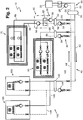
- Fig. 1 shows a schematic representation of a fluid system 10 with a main distribution circuit 40 and secondary circuits 50, 80, 100 and 120 of a first embodiment connected to it via line switches 52, 82, 102 and 122.
- the fluid system 10 has a generator circuit 20 and a main distribution circuit 40.
- the generator circuit 20 has a refrigeration machine 26 which is fluidly connected to the main distribution circuit 40 via a heat transfer device which is not specified in any more detail.
- the main distribution circuit 40 is connected to the generator circuit 20 via a hydraulic switch 30, a flow 42 of the main distribution circuit 40 opposite a flow 22 of the generator circuit 20 and a return 44 of the main distribution circuit 40 opposite a return 24 of the generator circuit 20.
- a pump 28 is arranged in the return line 24 and is provided for circulating the fluid in the generator circuit 20 via the heat transfer device and through the hydraulic switch 30.
- the main distribution circuit 40 is decoupled from the generator circuit 20 via the hydraulic switch 30.
- the refrigeration machine 26 is designed, for example, as a heat pump and, via the heat transfer device, applies the fluid which is guided in the main distribution circuit 40 and partly in the generator circuit 20 via the hydraulic switch 30 Temperature.
- the fluid is cooled down via the refrigeration machine 26 to such an extent that it has a temperature of ⁇ 4 ° C. in the flow 22 and flow 42 at the outlet of the hydraulic switch.
- Four secondary circuits 50, 80, 100 and 120 are connected to the flow 42.
- the secondary circuits 50, 80, 100, 120 are connected to the main distribution circuit 40 via line switches 52, 82, 102 and 122.
- the flow 56, 86, 106, 126 of the secondary circuits 50, 80, 100 and 120 is with the flow 42 of the main distribution circuit 40 and the return 58, 88, 108 and 128 of the secondary circuits 50, 80, 100 and 120 is with the return 44 of the main distribution circuit 40 connected.
- the secondary circuits 50, 80, 100 and 120 have in common that a pump 54, 84, 104, 124 is arranged in the return 58, 88, 108, 128 as a speed-controlled pump in the fluid flow direction downstream of the line switches 52, 82, 102, 122 , Shut-off devices and non-return valves are also shown, which on the one hand enable the respective secondary circuits 50, 80, 100, 120 to be separated and prevent fluid from flowing back. These are not explained in more detail below.
- the fluid system 10 is therefore particularly suitable for widely branched fluid circuits, such as are provided for example in supermarkets with a large number of cooling devices or in buildings.
- the pumps 54, 84, 104 and 124 regulate the amount of fluid that is passed through the secondary circuits 50, 80, 100, 120.
- a central circulation device can therefore be dispensed with in the main distribution circuit 40.
- Different consumers 70, 90, 110, 130 can be arranged in the respective secondary circuits 50, 80, 100, 120.
- several consumers 70, 90, 110 and 130 can also be provided in the respective secondary circuits 50, 80, 100 and 120.
- a consumer 70 is provided in the first secondary circuit 50 and is designed as a deep-freeze room.
- the secondary circuit 50 is connected to a further fluid circuit via a heat transfer device 60 which has a heat exchanger 62.
- the secondary circuit 50 has a pump 59 downstream of the line switch 52 in the fluid flow direction, which regulates the flow of the fluid through the heat transfer device 60 on the side of the secondary circuit 50, in cooperation with the pump 54.
- a pump 64 of the heat transfer device 60 regulates the flow of the fluid in the separate fluid circuit and is arranged in a return 68 of the separate fluid circuit.
- In a feed 66 of the separate fluid circuit there are electronic expansion valves 70 in the consumer, which are controlled by a stepper motor.
- the heat transfer device 60 is required to bring the temperature of the fluid in the flow 42 and flow 56 from approximately -4 ° Celsius to -20 ° Celsius.
- a plurality of consumers 70 can also be provided in parallel in the further fluid circuit.
- the second consumer 90 in the secondary circuit 80 is designed as a cold room.
- the temperature provided by the flow 42 and the flow 86 is sufficient for the cold room.
- the secondary circuit 80 therefore has no heat transfer device 60 or a comparable device.
- the flow 86 is divided in the consumer 90, a further pump being assigned to the respective lines. Depending on the cooling requirement, the performance of the pumps is increased or decreased. Accordingly, more fluid is delivered via the advance 86.
- the pump 84 is controlled in such a way that a larger amount of fluid is drawn off via the line switch 82 and fed to the return 44.
- the heated fluid which for example has a temperature of essentially 0 °, flows from the return 44 to the hydraulic switch 30.
- the fluid flows through the hydraulic switch 30 and is fed via the pump 28 to the heat transfer device of the generator circuit 20, in which a lowering takes place the temperature of the fluid takes place via the refrigerator 28.
- the fluid is then fed via the feed 22 and the hydraulic switch 30 back to the feed 42 and thus to the secondary circuits 50, 80, 100, 120.
- the secondary circuits 100 and 120 are essentially identical and have consumers 110 and 130, which are designed, for example, as refrigerated shelves. These have a separate circulation pump, so that consumers 110 and 130 draw the required amount of fluid depending on the cooling requirement required.
- each of the secondary circuits 50, 80, 100 and 120 has only one consumer 70, 90, 110 and 130.
- the fluid system 10 serves auxiliary circuits 50, 80, 100, 120, each with a plurality of consumers 70, 90, 110, 130 in the respective auxiliary circuits 50, 80, 100, 120 via the branch switches 52, 82, 102, 122 from the main distribution circuit 40 decouple.
- Fig. 2 shows a further embodiment of the fluid system 10, a secondary circuit 140 having two consumers 150 being provided instead of secondary circuits 100 and 120.
- the consumers 150 are designed as a cooling shelf and essentially correspond to the consumers 110 and 130.
- Fig. 2 shows the arrangement of several consumers 150 in a separate secondary circuit 140 for the secondary circuit 140, which is connected to the main distribution circuit 40 via a line switch 142. It is also possible to additionally provide other consumers, such as consumer 90, in a secondary circuit with consumers 150.
- the individual consumers 70, 90, 110, 130 and 150 are in after their training in Groups summarized.
- the freezer rooms are connected in parallel.
- several cold rooms (consumers 90) can also be combined in a separate secondary circuit 80 and connected in parallel.
- Cooling shelves (consumers 110, 130, 150) are, as in Fig. 2 indicated, also connected in parallel and combined in a secondary circuit 140.
- auxiliary circuits comprising, for example, only cooling shelves.
- the grouping of the individual consumers into the secondary groups 50, 80, 100, 120, 140 can take place in addition to the type of consumer 70, 90, 110, 130 and 150, depending on their position, for example in a supermarket.
- the energy requirement is lower than in the case of known designs from the prior art.
- individual secondary circuits are connected to a main distribution circuit without a line switch 52, 82, 102, 122 and 142.
- a central circulation pump for a main distribution circuit is provided in the designs from the prior art.
- the secondary circuits 50, 80, 100, 120 and 140 draw fluid from the main distribution circuit 40 via the line switches 52, 82, 102, 122, 142 and the associated pumps 54, 84, 104, 124 and 144 Volume flow of fluid in the main distribution circuit 40 therefore results directly from the need of Consumers 70, 90, 110, 130, 150, with the hydraulic balancing being carried out via line switches 52, 82, 102, 122 and 142. If there is a higher demand in one of the secondary groups 50, 80, 100, 120, 140, this does not lead to a loss of performance in the other secondary groups.
- cold can be stored via strand switches 52, 82, 102, 122 and 142 - depending on the dimensioning and design.
- the strand switches 52, 82, 102, 122 and 142 can therefore also serve as a buffer.
- Another advantage of the fluid system 10 in the event of a failure in one of the secondary circuits 50, 80, 100, 120, 140 is the restriction to the respective secondary circuit. This is also achieved by the decentralized arrangement of the line switches and the associated pumps. If one of these pumps 54, 84, 104, 124, 144 fails, this has no effect on one of the other pumps or on another secondary circuit. In the case of a central circulation pump in the main distribution circuit 40, as is customary in the prior art, failure of this circulation pump would lead to failure of the entire system. Such a system failure can cause great damage if, for example, the entire refrigerated goods have to be disposed of because the core temperature of the refrigerated goods has risen above a minimum temperature.
- the parallel connection of the secondary circuits 50, 80, 100, 120 and 140 via the associated line switches 52, 82, 102, 122, 142 and pumps 54, 84, 104, 124, 144 enables one in particular for fluid systems 10 with several parallel lines (secondary circuits) Demand-dependent supply of fluid, so that energy can be saved.
- the operation of the refrigeration machine 26 is further improved since both the hydraulic switch 30 as well as a balance and a hydraulic balance are provided via the line switches 52, 82, 102, 122 and 142.
Landscapes
- Engineering & Computer Science (AREA)
- Physics & Mathematics (AREA)
- Thermal Sciences (AREA)
- Chemical & Material Sciences (AREA)
- Combustion & Propulsion (AREA)
- Mechanical Engineering (AREA)
- General Engineering & Computer Science (AREA)
- Other Air-Conditioning Systems (AREA)
Priority Applications (1)
| Application Number | Priority Date | Filing Date | Title |
|---|---|---|---|
| PL19182186T PL3587968T3 (pl) | 2018-06-27 | 2019-06-25 | System płynowy |
Applications Claiming Priority (1)
| Application Number | Priority Date | Filing Date | Title |
|---|---|---|---|
| DE102018115423.2A DE102018115423B4 (de) | 2018-06-27 | 2018-06-27 | Fluidsystem |
Publications (2)
| Publication Number | Publication Date |
|---|---|
| EP3587968A1 true EP3587968A1 (fr) | 2020-01-01 |
| EP3587968B1 EP3587968B1 (fr) | 2021-12-01 |
Family
ID=67105706
Family Applications (1)
| Application Number | Title | Priority Date | Filing Date |
|---|---|---|---|
| EP19182186.7A Active EP3587968B1 (fr) | 2018-06-27 | 2019-06-25 | Système fluidique |
Country Status (5)
| Country | Link |
|---|---|
| EP (1) | EP3587968B1 (fr) |
| DE (1) | DE102018115423B4 (fr) |
| DK (1) | DK3587968T3 (fr) |
| ES (1) | ES2907603T3 (fr) |
| PL (1) | PL3587968T3 (fr) |
Cited By (2)
| Publication number | Priority date | Publication date | Assignee | Title |
|---|---|---|---|---|
| EP4556800A1 (fr) * | 2023-11-20 | 2025-05-21 | BDR Thermea Group B.V. | Mode d'équilibrage hydronique dans un système de chauffage multi-source |
| DE102024132974A1 (de) | 2024-08-16 | 2026-02-19 | Liebherr-Hausgeräte Ochsenhausen GmbH | Kühl- und/oder Gefriergerät |
Families Citing this family (1)
| Publication number | Priority date | Publication date | Assignee | Title |
|---|---|---|---|---|
| DE102024117714A1 (de) * | 2024-06-24 | 2025-12-24 | Vaillant Gmbh | Hybridheizungsanlage |
Citations (4)
| Publication number | Priority date | Publication date | Assignee | Title |
|---|---|---|---|---|
| AT12588U1 (de) * | 2011-03-23 | 2012-08-15 | Thomas Ing Stejskal | Vorrichtung zur bereitstellung von thermischer energie |
| DE202013105851U1 (de) * | 2013-12-20 | 2014-02-24 | Sinusverteiler Gmbh | Sammler- und Verteilereinheit für das Wärmeträgermedium einer Heizungsanlage mit mehreren Heizkesseln und mehreren Heizkreisen |
| WO2015024554A1 (fr) * | 2013-08-20 | 2015-02-26 | Gwk-Kuhlmann Gesellschaft Für Wärme-, Kälte- Und Klimatechnik Mit Beschränkter Haftung | Système de régulation de température et de récupération de chaleur pour au moins une machine dont la température peut être régulée au moyen d'un fluide et procédé pour faire fonctionner un système de régulation de température et de récupération de chaleur |
| EP3076106A2 (fr) | 2015-03-30 | 2016-10-05 | Viessmann Werke GmbH & Co. KG | Unite de refroidissement |
Family Cites Families (2)
| Publication number | Priority date | Publication date | Assignee | Title |
|---|---|---|---|---|
| DE102016002690A1 (de) * | 2016-03-08 | 2017-09-14 | Paw Gmbh & Co. Kg | Verfahren zur hydraulischen Entkopplung mehrerer, parallel geschalteter Fluidkreisläufe |
| DE102017123705A1 (de) * | 2017-10-12 | 2019-04-18 | Viessmann Werke Gmbh & Co Kg | Kühlmöbel mit integrierter hydraulischer Regelung und Kühlsystem |
-
2018
- 2018-06-27 DE DE102018115423.2A patent/DE102018115423B4/de not_active Expired - Fee Related
-
2019
- 2019-06-25 PL PL19182186T patent/PL3587968T3/pl unknown
- 2019-06-25 EP EP19182186.7A patent/EP3587968B1/fr active Active
- 2019-06-25 ES ES19182186T patent/ES2907603T3/es active Active
- 2019-06-25 DK DK19182186.7T patent/DK3587968T3/da active
Patent Citations (4)
| Publication number | Priority date | Publication date | Assignee | Title |
|---|---|---|---|---|
| AT12588U1 (de) * | 2011-03-23 | 2012-08-15 | Thomas Ing Stejskal | Vorrichtung zur bereitstellung von thermischer energie |
| WO2015024554A1 (fr) * | 2013-08-20 | 2015-02-26 | Gwk-Kuhlmann Gesellschaft Für Wärme-, Kälte- Und Klimatechnik Mit Beschränkter Haftung | Système de régulation de température et de récupération de chaleur pour au moins une machine dont la température peut être régulée au moyen d'un fluide et procédé pour faire fonctionner un système de régulation de température et de récupération de chaleur |
| DE202013105851U1 (de) * | 2013-12-20 | 2014-02-24 | Sinusverteiler Gmbh | Sammler- und Verteilereinheit für das Wärmeträgermedium einer Heizungsanlage mit mehreren Heizkesseln und mehreren Heizkreisen |
| EP3076106A2 (fr) | 2015-03-30 | 2016-10-05 | Viessmann Werke GmbH & Co. KG | Unite de refroidissement |
Non-Patent Citations (1)
| Title |
|---|
| DELPECH P: "BOUTEILLES CASSE-PRESSION ET DE MELANGE, CONCEPTION ET COMPORTEMENT", CFP CHAUD FROID PLOMBERIE, EDITIONS PARISIENNES. PARIS, FR, no. 596, 1 November 1997 (1997-11-01), pages 119 - 124, XP000724699, ISSN: 0750-1552 * |
Cited By (3)
| Publication number | Priority date | Publication date | Assignee | Title |
|---|---|---|---|---|
| EP4556800A1 (fr) * | 2023-11-20 | 2025-05-21 | BDR Thermea Group B.V. | Mode d'équilibrage hydronique dans un système de chauffage multi-source |
| WO2025109015A1 (fr) * | 2023-11-20 | 2025-05-30 | Bdr Thermea Group B.V. | Mode d'équilibrage hydronique dans un système de chauffage à sources multiples |
| DE102024132974A1 (de) | 2024-08-16 | 2026-02-19 | Liebherr-Hausgeräte Ochsenhausen GmbH | Kühl- und/oder Gefriergerät |
Also Published As
| Publication number | Publication date |
|---|---|
| ES2907603T3 (es) | 2022-04-25 |
| DK3587968T3 (da) | 2022-02-21 |
| PL3587968T3 (pl) | 2022-04-19 |
| EP3587968B1 (fr) | 2021-12-01 |
| DE102018115423A1 (de) | 2020-01-02 |
| DE102018115423B4 (de) | 2021-10-21 |
Similar Documents
| Publication | Publication Date | Title |
|---|---|---|
| DE112008003700B4 (de) | Vorrichtung zur Steigerung der Heiz- und Kühlleistung einer Wärmepumpe in der Wärmerückgewinnung in Lüftungsgeräten | |
| DE602004006674T2 (de) | Kryogene Kälteanlage und Verfahren mit Kältespeicher | |
| DE10361645B4 (de) | Kühlsystem zum Kühlen von wärmeerzeugenden Einrichtungen in einem Flugzeug | |
| DE102005061599A1 (de) | Modulares Kühlsystem und Kälteerzeugungseinrichtung für ein solches Kühlsystem | |
| DE2157079A1 (de) | Zweistufige Kälteanlage | |
| EP2242962B1 (fr) | Dispositif de climatisation modulaire et procédé d'utilisation | |
| DE2951752C2 (de) | Schalteinrichtung für eine Kälteanlage | |
| EP3587968B1 (fr) | Système fluidique | |
| DE102017109357B4 (de) | Kühlmöbel mit Speicher und Kühlsystem | |
| DE69208038T2 (de) | Automatischer Leistungsausgleich einer Kühlanlage | |
| EP3270066A1 (fr) | Procédé de fonctionnement d'un système d'alimentation en énergie pourvu d'un accumulateur de chaleur latente, système d'alimentation en énergie permettant de mettre en oeuvre le procédé et champ de collecteur pour un système d'alimentation en énergie | |
| EP3244136A1 (fr) | Module réfrigérant | |
| DE102015119362A1 (de) | Kühlsystem und Verfahren zum Betreiben des Kühlsystems | |
| DE202012103717U1 (de) | Thermischer Speicher für Kälteanlagen | |
| EP3438574B1 (fr) | Installation frigorifique et procédé de réglage d'une installation frigorifique | |
| EP3076111B1 (fr) | Système fluidique et procédé de commande d'un système fluidique | |
| EP3076110A1 (fr) | Systeme fluidique et procede de commande d'un systeme fluidique | |
| EP3695179B1 (fr) | Meuble réfrigéré à commande hydraulique intégrée et système de refroidissement | |
| WO2017013163A1 (fr) | Système de pompe à chaleur | |
| EP3076109B1 (fr) | Systeme de refroidissement et procede de fonctionnement du systeme de refroidissement | |
| EP3601902A1 (fr) | Appareil frigorifique et procédé de fonctionnement associé | |
| EP3866562B1 (fr) | Module de compresseur, système de refroidissement et/ou de chauffage pourvu de modules de compresseur et procédé de fonctionnement d'un système de refroidissement et/ou de chauffage | |
| EP3076105B1 (fr) | Système de refroidissement | |
| EP4417905A1 (fr) | Dispositif pour chauffer la porte d'un meuble frigorifique | |
| EP4411253A1 (fr) | Système d'alimentation d'une pluralité d'unités de consommation placées dans un bâtiment en exergie |
Legal Events
| Date | Code | Title | Description |
|---|---|---|---|
| PUAI | Public reference made under article 153(3) epc to a published international application that has entered the european phase |
Free format text: ORIGINAL CODE: 0009012 |
|
| STAA | Information on the status of an ep patent application or granted ep patent |
Free format text: STATUS: THE APPLICATION HAS BEEN PUBLISHED |
|
| AK | Designated contracting states |
Kind code of ref document: A1 Designated state(s): AL AT BE BG CH CY CZ DE DK EE ES FI FR GB GR HR HU IE IS IT LI LT LU LV MC MK MT NL NO PL PT RO RS SE SI SK SM TR |
|
| AX | Request for extension of the european patent |
Extension state: BA ME |
|
| STAA | Information on the status of an ep patent application or granted ep patent |
Free format text: STATUS: REQUEST FOR EXAMINATION WAS MADE |
|
| 17P | Request for examination filed |
Effective date: 20200305 |
|
| RBV | Designated contracting states (corrected) |
Designated state(s): AL AT BE BG CH CY CZ DE DK EE ES FI FR GB GR HR HU IE IS IT LI LT LU LV MC MK MT NL NO PL PT RO RS SE SI SK SM TR |
|
| GRAP | Despatch of communication of intention to grant a patent |
Free format text: ORIGINAL CODE: EPIDOSNIGR1 |
|
| STAA | Information on the status of an ep patent application or granted ep patent |
Free format text: STATUS: GRANT OF PATENT IS INTENDED |
|
| RIC1 | Information provided on ipc code assigned before grant |
Ipc: F24D 3/10 20060101ALI20210804BHEP Ipc: F25D 17/02 20060101AFI20210804BHEP |
|
| INTG | Intention to grant announced |
Effective date: 20210826 |
|
| GRAS | Grant fee paid |
Free format text: ORIGINAL CODE: EPIDOSNIGR3 |
|
| GRAA | (expected) grant |
Free format text: ORIGINAL CODE: 0009210 |
|
| STAA | Information on the status of an ep patent application or granted ep patent |
Free format text: STATUS: THE PATENT HAS BEEN GRANTED |
|
| RAP1 | Party data changed (applicant data changed or rights of an application transferred) |
Owner name: VIESSMANN REFRIGERATION SOLUTIONS GMBH |
|
| AK | Designated contracting states |
Kind code of ref document: B1 Designated state(s): AL AT BE BG CH CY CZ DE DK EE ES FI FR GB GR HR HU IE IS IT LI LT LU LV MC MK MT NL NO PL PT RO RS SE SI SK SM TR |
|
| REG | Reference to a national code |
Ref country code: GB Ref legal event code: FG4D Free format text: NOT ENGLISH |
|
| REG | Reference to a national code |
Ref country code: AT Ref legal event code: REF Ref document number: 1452135 Country of ref document: AT Kind code of ref document: T Effective date: 20211215 Ref country code: CH Ref legal event code: EP |
|
| REG | Reference to a national code |
Ref country code: IE Ref legal event code: FG4D Free format text: LANGUAGE OF EP DOCUMENT: GERMAN |
|
| REG | Reference to a national code |
Ref country code: DE Ref legal event code: R096 Ref document number: 502019002889 Country of ref document: DE |
|
| REG | Reference to a national code |
Ref country code: DK Ref legal event code: T3 Effective date: 20220217 |
|
| REG | Reference to a national code |
Ref country code: NO Ref legal event code: T2 Effective date: 20211201 |
|
| REG | Reference to a national code |
Ref country code: FI Ref legal event code: FGE |
|
| REG | Reference to a national code |
Ref country code: SE Ref legal event code: TRGR |
|
| REG | Reference to a national code |
Ref country code: NL Ref legal event code: FP |
|
| REG | Reference to a national code |
Ref country code: LT Ref legal event code: MG9D |
|
| REG | Reference to a national code |
Ref country code: ES Ref legal event code: FG2A Ref document number: 2907603 Country of ref document: ES Kind code of ref document: T3 Effective date: 20220425 |
|
| PG25 | Lapsed in a contracting state [announced via postgrant information from national office to epo] |
Ref country code: RS Free format text: LAPSE BECAUSE OF FAILURE TO SUBMIT A TRANSLATION OF THE DESCRIPTION OR TO PAY THE FEE WITHIN THE PRESCRIBED TIME-LIMIT Effective date: 20211201 Ref country code: LT Free format text: LAPSE BECAUSE OF FAILURE TO SUBMIT A TRANSLATION OF THE DESCRIPTION OR TO PAY THE FEE WITHIN THE PRESCRIBED TIME-LIMIT Effective date: 20211201 Ref country code: BG Free format text: LAPSE BECAUSE OF FAILURE TO SUBMIT A TRANSLATION OF THE DESCRIPTION OR TO PAY THE FEE WITHIN THE PRESCRIBED TIME-LIMIT Effective date: 20220301 |
|
| PG25 | Lapsed in a contracting state [announced via postgrant information from national office to epo] |
Ref country code: LV Free format text: LAPSE BECAUSE OF FAILURE TO SUBMIT A TRANSLATION OF THE DESCRIPTION OR TO PAY THE FEE WITHIN THE PRESCRIBED TIME-LIMIT Effective date: 20211201 Ref country code: HR Free format text: LAPSE BECAUSE OF FAILURE TO SUBMIT A TRANSLATION OF THE DESCRIPTION OR TO PAY THE FEE WITHIN THE PRESCRIBED TIME-LIMIT Effective date: 20211201 Ref country code: GR Free format text: LAPSE BECAUSE OF FAILURE TO SUBMIT A TRANSLATION OF THE DESCRIPTION OR TO PAY THE FEE WITHIN THE PRESCRIBED TIME-LIMIT Effective date: 20220302 |
|
| PG25 | Lapsed in a contracting state [announced via postgrant information from national office to epo] |
Ref country code: SM Free format text: LAPSE BECAUSE OF FAILURE TO SUBMIT A TRANSLATION OF THE DESCRIPTION OR TO PAY THE FEE WITHIN THE PRESCRIBED TIME-LIMIT Effective date: 20211201 Ref country code: SK Free format text: LAPSE BECAUSE OF FAILURE TO SUBMIT A TRANSLATION OF THE DESCRIPTION OR TO PAY THE FEE WITHIN THE PRESCRIBED TIME-LIMIT Effective date: 20211201 Ref country code: RO Free format text: LAPSE BECAUSE OF FAILURE TO SUBMIT A TRANSLATION OF THE DESCRIPTION OR TO PAY THE FEE WITHIN THE PRESCRIBED TIME-LIMIT Effective date: 20211201 Ref country code: PT Free format text: LAPSE BECAUSE OF FAILURE TO SUBMIT A TRANSLATION OF THE DESCRIPTION OR TO PAY THE FEE WITHIN THE PRESCRIBED TIME-LIMIT Effective date: 20220401 Ref country code: EE Free format text: LAPSE BECAUSE OF FAILURE TO SUBMIT A TRANSLATION OF THE DESCRIPTION OR TO PAY THE FEE WITHIN THE PRESCRIBED TIME-LIMIT Effective date: 20211201 Ref country code: CZ Free format text: LAPSE BECAUSE OF FAILURE TO SUBMIT A TRANSLATION OF THE DESCRIPTION OR TO PAY THE FEE WITHIN THE PRESCRIBED TIME-LIMIT Effective date: 20211201 |
|
| PGFP | Annual fee paid to national office [announced via postgrant information from national office to epo] |
Ref country code: SE Payment date: 20220625 Year of fee payment: 4 Ref country code: NO Payment date: 20220628 Year of fee payment: 4 Ref country code: NL Payment date: 20220627 Year of fee payment: 4 |
|
| PGFP | Annual fee paid to national office [announced via postgrant information from national office to epo] |
Ref country code: BE Payment date: 20220625 Year of fee payment: 4 |
|
| REG | Reference to a national code |
Ref country code: DE Ref legal event code: R097 Ref document number: 502019002889 Country of ref document: DE |
|
| PG25 | Lapsed in a contracting state [announced via postgrant information from national office to epo] |
Ref country code: IS Free format text: LAPSE BECAUSE OF FAILURE TO SUBMIT A TRANSLATION OF THE DESCRIPTION OR TO PAY THE FEE WITHIN THE PRESCRIBED TIME-LIMIT Effective date: 20220401 |
|
| PGFP | Annual fee paid to national office [announced via postgrant information from national office to epo] |
Ref country code: FR Payment date: 20220625 Year of fee payment: 4 |
|
| PLBE | No opposition filed within time limit |
Free format text: ORIGINAL CODE: 0009261 |
|
| STAA | Information on the status of an ep patent application or granted ep patent |
Free format text: STATUS: NO OPPOSITION FILED WITHIN TIME LIMIT |
|
| PG25 | Lapsed in a contracting state [announced via postgrant information from national office to epo] |
Ref country code: AL Free format text: LAPSE BECAUSE OF FAILURE TO SUBMIT A TRANSLATION OF THE DESCRIPTION OR TO PAY THE FEE WITHIN THE PRESCRIBED TIME-LIMIT Effective date: 20211201 |
|
| PGFP | Annual fee paid to national office [announced via postgrant information from national office to epo] |
Ref country code: IT Payment date: 20220630 Year of fee payment: 4 Ref country code: ES Payment date: 20220701 Year of fee payment: 4 |
|
| 26N | No opposition filed |
Effective date: 20220902 |
|
| PG25 | Lapsed in a contracting state [announced via postgrant information from national office to epo] |
Ref country code: SI Free format text: LAPSE BECAUSE OF FAILURE TO SUBMIT A TRANSLATION OF THE DESCRIPTION OR TO PAY THE FEE WITHIN THE PRESCRIBED TIME-LIMIT Effective date: 20211201 |
|
| PGFP | Annual fee paid to national office [announced via postgrant information from national office to epo] |
Ref country code: CH Payment date: 20220627 Year of fee payment: 4 |
|
| PG25 | Lapsed in a contracting state [announced via postgrant information from national office to epo] |
Ref country code: MC Free format text: LAPSE BECAUSE OF FAILURE TO SUBMIT A TRANSLATION OF THE DESCRIPTION OR TO PAY THE FEE WITHIN THE PRESCRIBED TIME-LIMIT Effective date: 20211201 |
|
| PG25 | Lapsed in a contracting state [announced via postgrant information from national office to epo] |
Ref country code: LU Free format text: LAPSE BECAUSE OF NON-PAYMENT OF DUE FEES Effective date: 20220625 Ref country code: IE Free format text: LAPSE BECAUSE OF NON-PAYMENT OF DUE FEES Effective date: 20220625 |
|
| P01 | Opt-out of the competence of the unified patent court (upc) registered |
Effective date: 20230512 |
|
| PGFP | Annual fee paid to national office [announced via postgrant information from national office to epo] |
Ref country code: DK Payment date: 20230621 Year of fee payment: 5 Ref country code: DE Payment date: 20230531 Year of fee payment: 5 |
|
| PGFP | Annual fee paid to national office [announced via postgrant information from national office to epo] |
Ref country code: PL Payment date: 20230524 Year of fee payment: 5 Ref country code: FI Payment date: 20230620 Year of fee payment: 5 |
|
| REG | Reference to a national code |
Ref country code: NO Ref legal event code: MMEP |
|
| REG | Reference to a national code |
Ref country code: SE Ref legal event code: EUG |
|
| REG | Reference to a national code |
Ref country code: CH Ref legal event code: PL |
|
| REG | Reference to a national code |
Ref country code: NL Ref legal event code: MM Effective date: 20230701 |
|
| REG | Reference to a national code |
Ref country code: BE Ref legal event code: MM Effective date: 20230630 |
|
| GBPC | Gb: european patent ceased through non-payment of renewal fee |
Effective date: 20230625 |
|
| PG25 | Lapsed in a contracting state [announced via postgrant information from national office to epo] |
Ref country code: NL Free format text: LAPSE BECAUSE OF NON-PAYMENT OF DUE FEES Effective date: 20230701 |
|
| PG25 | Lapsed in a contracting state [announced via postgrant information from national office to epo] |
Ref country code: MK Free format text: LAPSE BECAUSE OF FAILURE TO SUBMIT A TRANSLATION OF THE DESCRIPTION OR TO PAY THE FEE WITHIN THE PRESCRIBED TIME-LIMIT Effective date: 20211201 Ref country code: CY Free format text: LAPSE BECAUSE OF FAILURE TO SUBMIT A TRANSLATION OF THE DESCRIPTION OR TO PAY THE FEE WITHIN THE PRESCRIBED TIME-LIMIT Effective date: 20211201 Ref country code: GB Free format text: LAPSE BECAUSE OF NON-PAYMENT OF DUE FEES Effective date: 20230625 Ref country code: CH Free format text: LAPSE BECAUSE OF NON-PAYMENT OF DUE FEES Effective date: 20230630 |
|
| PG25 | Lapsed in a contracting state [announced via postgrant information from national office to epo] |
Ref country code: SE Free format text: LAPSE BECAUSE OF NON-PAYMENT OF DUE FEES Effective date: 20230626 Ref country code: NO Free format text: LAPSE BECAUSE OF NON-PAYMENT OF DUE FEES Effective date: 20230630 Ref country code: HU Free format text: LAPSE BECAUSE OF FAILURE TO SUBMIT A TRANSLATION OF THE DESCRIPTION OR TO PAY THE FEE WITHIN THE PRESCRIBED TIME-LIMIT; INVALID AB INITIO Effective date: 20190625 Ref country code: FR Free format text: LAPSE BECAUSE OF NON-PAYMENT OF DUE FEES Effective date: 20230630 Ref country code: BE Free format text: LAPSE BECAUSE OF NON-PAYMENT OF DUE FEES Effective date: 20230630 |
|
| PG25 | Lapsed in a contracting state [announced via postgrant information from national office to epo] |
Ref country code: TR Free format text: LAPSE BECAUSE OF FAILURE TO SUBMIT A TRANSLATION OF THE DESCRIPTION OR TO PAY THE FEE WITHIN THE PRESCRIBED TIME-LIMIT Effective date: 20211201 |
|
| REG | Reference to a national code |
Ref country code: ES Ref legal event code: FD2A Effective date: 20240729 |
|
| PG25 | Lapsed in a contracting state [announced via postgrant information from national office to epo] |
Ref country code: IT Free format text: LAPSE BECAUSE OF NON-PAYMENT OF DUE FEES Effective date: 20230625 |
|
| PG25 | Lapsed in a contracting state [announced via postgrant information from national office to epo] |
Ref country code: MT Free format text: LAPSE BECAUSE OF FAILURE TO SUBMIT A TRANSLATION OF THE DESCRIPTION OR TO PAY THE FEE WITHIN THE PRESCRIBED TIME-LIMIT Effective date: 20211201 |
|
| PG25 | Lapsed in a contracting state [announced via postgrant information from national office to epo] |
Ref country code: ES Free format text: LAPSE BECAUSE OF NON-PAYMENT OF DUE FEES Effective date: 20230626 |
|
| PG25 | Lapsed in a contracting state [announced via postgrant information from national office to epo] |
Ref country code: ES Free format text: LAPSE BECAUSE OF NON-PAYMENT OF DUE FEES Effective date: 20230626 |
|
| REG | Reference to a national code |
Ref country code: DE Ref legal event code: R119 Ref document number: 502019002889 Country of ref document: DE |
|
| PG25 | Lapsed in a contracting state [announced via postgrant information from national office to epo] |
Ref country code: FI Free format text: LAPSE BECAUSE OF NON-PAYMENT OF DUE FEES Effective date: 20240625 |
|
| REG | Reference to a national code |
Ref country code: DK Ref legal event code: EBP Effective date: 20240630 |
|
| PG25 | Lapsed in a contracting state [announced via postgrant information from national office to epo] |
Ref country code: FI Free format text: LAPSE BECAUSE OF NON-PAYMENT OF DUE FEES Effective date: 20240625 |
|
| PG25 | Lapsed in a contracting state [announced via postgrant information from national office to epo] |
Ref country code: DE Free format text: LAPSE BECAUSE OF NON-PAYMENT OF DUE FEES Effective date: 20250101 |
|
| PG25 | Lapsed in a contracting state [announced via postgrant information from national office to epo] |
Ref country code: DK Free format text: LAPSE BECAUSE OF NON-PAYMENT OF DUE FEES Effective date: 20240630 |
|
| REG | Reference to a national code |
Ref country code: AT Ref legal event code: MM01 Ref document number: 1452135 Country of ref document: AT Kind code of ref document: T Effective date: 20240625 |
|
| PG25 | Lapsed in a contracting state [announced via postgrant information from national office to epo] |
Ref country code: PL Free format text: LAPSE BECAUSE OF NON-PAYMENT OF DUE FEES Effective date: 20240625 |
|
| PG25 | Lapsed in a contracting state [announced via postgrant information from national office to epo] |
Ref country code: AT Free format text: LAPSE BECAUSE OF NON-PAYMENT OF DUE FEES Effective date: 20240625 |
|
| PGFP | Annual fee paid to national office [announced via postgrant information from national office to epo] |
Ref country code: AT Payment date: 20260410 Year of fee payment: 5 |