EP3078960A2 - Vorrichtung und verfahren zur inspektion eines drahtsegments - Google Patents
Vorrichtung und verfahren zur inspektion eines drahtsegments Download PDFInfo
- Publication number
- EP3078960A2 EP3078960A2 EP16163687.3A EP16163687A EP3078960A2 EP 3078960 A2 EP3078960 A2 EP 3078960A2 EP 16163687 A EP16163687 A EP 16163687A EP 3078960 A2 EP3078960 A2 EP 3078960A2
- Authority
- EP
- European Patent Office
- Prior art keywords
- mirrors
- wire segment
- vantage point
- reflection
- array
- Prior art date
- Legal status (The legal status is an assumption and is not a legal conclusion. Google has not performed a legal analysis and makes no representation as to the accuracy of the status listed.)
- Granted
Links
Images



Classifications
-
- G—PHYSICS
- G01—MEASURING; TESTING
- G01N—INVESTIGATING OR ANALYSING MATERIALS BY DETERMINING THEIR CHEMICAL OR PHYSICAL PROPERTIES
- G01N21/00—Investigating or analysing materials by the use of optical means, i.e. using sub-millimetre waves, infrared, visible or ultraviolet light
- G01N21/84—Systems specially adapted for particular applications
- G01N21/88—Investigating the presence of flaws or contamination
- G01N21/95—Investigating the presence of flaws or contamination characterised by the material or shape of the object to be examined
- G01N21/952—Inspecting the exterior surface of cylindrical bodies or wires
-
- G—PHYSICS
- G01—MEASURING; TESTING
- G01N—INVESTIGATING OR ANALYSING MATERIALS BY DETERMINING THEIR CHEMICAL OR PHYSICAL PROPERTIES
- G01N21/00—Investigating or analysing materials by the use of optical means, i.e. using sub-millimetre waves, infrared, visible or ultraviolet light
- G01N21/84—Systems specially adapted for particular applications
- G01N21/88—Investigating the presence of flaws or contamination
- G01N21/8806—Specially adapted optical and illumination features
-
- G—PHYSICS
- G01—MEASURING; TESTING
- G01N—INVESTIGATING OR ANALYSING MATERIALS BY DETERMINING THEIR CHEMICAL OR PHYSICAL PROPERTIES
- G01N21/00—Investigating or analysing materials by the use of optical means, i.e. using sub-millimetre waves, infrared, visible or ultraviolet light
- G01N21/84—Systems specially adapted for particular applications
- G01N21/88—Investigating the presence of flaws or contamination
- G01N21/8803—Visual inspection
-
- G—PHYSICS
- G06—COMPUTING OR CALCULATING; COUNTING
- G06T—IMAGE DATA PROCESSING OR GENERATION, IN GENERAL
- G06T7/00—Image analysis
- G06T7/0002—Inspection of images, e.g. flaw detection
- G06T7/0004—Industrial image inspection
-
- G—PHYSICS
- G01—MEASURING; TESTING
- G01N—INVESTIGATING OR ANALYSING MATERIALS BY DETERMINING THEIR CHEMICAL OR PHYSICAL PROPERTIES
- G01N21/00—Investigating or analysing materials by the use of optical means, i.e. using sub-millimetre waves, infrared, visible or ultraviolet light
- G01N21/84—Systems specially adapted for particular applications
- G01N21/88—Investigating the presence of flaws or contamination
-
- G—PHYSICS
- G01—MEASURING; TESTING
- G01N—INVESTIGATING OR ANALYSING MATERIALS BY DETERMINING THEIR CHEMICAL OR PHYSICAL PROPERTIES
- G01N2201/00—Features of devices classified in G01N21/00
- G01N2201/06—Illumination; Optics
- G01N2201/068—Optics, miscellaneous
Definitions
- the field of the present disclosure relates generally to wire inspection techniques and, more specifically, to an apparatus and methods that facilitate efficient inspection of a wire segment.
- electrical wires that must undergo a series of processing steps prior to their installation within the assembly. More specifically, electrical wires are generally delivered in large spools, such that each portion of electrical wire is measured and cut, each end of the cut electrical wire is stripped and inserted into a specific end piece, and each end is crimped to facilitate sufficient electrical contact with a lug, pin, or socket, for example.
- electrical wires are generally delivered in large spools, such that each portion of electrical wire is measured and cut, each end of the cut electrical wire is stripped and inserted into a specific end piece, and each end is crimped to facilitate sufficient electrical contact with a lug, pin, or socket, for example.
- Several errors may occur during one or more of these processing steps. For example, an insufficient amount of electrically conductive material may be exposed after the stripping step, or stray strands of electrically conductive material may be exposed if an end of the electrical wire is improperly inserted into a lug, pin, or socket.
- At least some of these electrical wires are visually inspected by a technician to ensure the electrical wire has been properly processed prior to its installation within the assembly. This inspection is a time-consuming and laborious task because the entire area about the processed portions of the electrical wire must be inspected carefully, and there is typically a large number of such wire segments to be inspected.
- an apparatus for use in inspecting a wire segment includes a guide tube sized to receive the wire segment, and an array of mirrors positioned about the guide tube. Each mirror in the array is oriented such that a reflection of the wire segment in the array of mirrors forms a circumferential view of at least a portion of the wire segment, and such that the reflection from each mirror is within a field of view from a single vantage point.
- a system for use in inspecting a wire segment includes a guide tube sized to receive the wire segment, and an array of mirrors positioned about the guide tube. Each mirror in the array is oriented such that a reflection of the wire segment in the array of mirrors forms a circumferential view of at least a portion of the wire segment, and such that the reflection from each mirror is within a field of view from a single vantage point.
- the system also includes a visual imaging device positioned at the single vantage point. The visual imaging device is configured to capture at least one image of the reflection of the wire segment.
- a method of inspecting a wire segment includes positioning the wire segment within a guide tube, orienting mirrors in an array of mirrors positioned about the guide tube such that a reflection of the wire segment from each mirror in the array of mirrors forms a circumferential view of at least a portion of the wire segment, and such that the reflection from each mirror is within a field of view from a single vantage point.
- the method further includes determining defects in the wire segment from the reflection of the at least a portion of the wire segment.
- the apparatus includes a guide tube sized to receive the wire segment and an array of mirrors positioned about the guide tube.
- the mirrors in the array are oriented such that a full circumferential view of the wire segment can be viewed from a single vantage point.
- mirrors in the array can be arranged in different configurations such that each configuration enables the full circumferential view to be visible from the single vantage point.
- a visual imaging device is used to inspect the wire segment by capturing an image of a reflection of the wire segment from the array of mirrors.
- each configuration of the array of mirrors enables the full circumferential view to be visible in a reflection therefrom, at least some of the configurations facilitate reducing the number of pixels needed to achieve an adequate spatial resolution in a full view of the wire segment in the image captured by the visual imaging device. More specifically, at least some of the configurations facilitate reducing the number of pixels in the pixel array that contain no useful information when the image is captured from the single vantage point. As such, reducing the number of pixels enables faster processing speeds of the images, reduces memory storage requirements, and thus reduces costs associated with visual imaging devices described herein.
- implementations of the disclosure may be described in the context of an aircraft manufacturing and service method 100 (shown in FIG. 1 ) and via an aircraft 102 (shown in FIG. 2 ).
- pre-production including specification and design 104 data of aircraft 102 may be used during the manufacturing process and other materials associated with the airframe may be procured 106.
- component and subassembly manufacturing 108 and system integration 110 of aircraft 102 occurs, prior to aircraft 102 entering its certification and delivery process 112.
- aircraft 102 may be placed in service 114.
- aircraft 102 is scheduled for periodic, routine, and scheduled maintenance and service 116, including any modification, reconfiguration, and/or refurbishment, for example.
- manufacturing and service method 100 may be implemented via platforms other than an aircraft.
- Each portion and process associated with aircraft manufacturing and/or service 100 may be performed or completed by a system integrator, a third party, and/or an operator (e.g., a customer).
- a system integrator may include without limitation any number of aircraft manufacturers and major-system subcontractors
- a third party may include without limitation any number of venders, subcontractors, and suppliers
- an operator may be an airline, leasing company, military entity, service organization, and so on.
- aircraft 102 produced via method 100 may include an airframe 118 having a plurality of systems 120 and an interior 122.
- high-level systems 120 include one or more of a propulsion system 124, an electrical system 126, a hydraulic system 128, and/or an environmental system 130. Any number of other systems may be included.
- Apparatus and methods embodied herein may be employed during any one or more of the stages of method 100.
- components or subassemblies corresponding to component and subassembly production process 108 may be fabricated or manufactured in a manner similar to components or subassemblies produced while aircraft 102 is in service 114.
- one or more apparatus implementations, method implementations, or a combination thereof may be utilized during the production stages 108 and 110, for example, by substantially expediting assembly of, and/or reducing the cost of assembly of aircraft 102.
- apparatus implementations, method implementations, or a combination thereof may be utilized while aircraft 102 is being serviced or maintained, for example, during scheduled maintenance and service 116.
- aircraft may include, but is not limited to only including, airplanes, unmanned aerial vehicles (UAVs), gliders, helicopters, and/or any other object that travels through airspace.
- UAVs unmanned aerial vehicles
- helicopters helicopters
- any other object that travels through airspace may be used in any manufacturing and/or service operation.
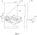
- FIG. 3 is a schematic side view illustration of an exemplary wire inspection system 200
- FIG. 4 is a view of wire inspection system 200 from an exemplary vantage point 202.
- wire inspection system 200 a viewing apparatus 204 and a visual imaging device 206.
- Viewing apparatus 204 includes a guide tube 208 sized to receive a wire segment 210 therethrough, and an array 212 of mirrors 214 positioned about guide tube 208.
- Each mirror 214 in array 212 is oriented such that a reflection of wire segment 210 in array 212 forms a full circumferential view of at least a portion of wire segment 210.
- each mirror 214 in array 212 is oriented such that the reflection from each mirror 214 is within the field of view from a single vantage point 202. More specifically, in one implementation, and as will be described in more detail below, visual imaging device 206 is positioned at vantage point 202. Visual imaging device 206 captures at least one image of wire segment 210 in the reflection.
- array 212 includes at least three mirrors 214 spaced at regular intervals about guide tube 208.
- each mirror 214 is positioned at 120° intervals about guide tube 208 to enable the full circumferential view of wire segment 210 to be formed in the sum of the reflections from each mirror 214.
- At least three mirrors 214 are used in array 212 to ensure proper viewing angles of the cylindrically-shaped wire segment 210 are obtained in the reflections from each mirror 214.
- array 212 can include any number of mirrors 214 that enables wire inspection system 200 to function as described herein.
- mirrors 214 can be spaced from each other at irregular intervals about guide tube 208.
- guide tube 208 is sized to receive wire segment 210 therein. More specifically, guide tube 208 constrains wire segment 210 such that it extends substantially coaxially with a centerline 216 of guide tube 208. As such, wire segment 210 remains within the field of view from vantage point 202 and facilitates ensuring the full circumferential view of wire segment 210 is formed. In the exemplary implementation, vantage point 202 is substantially coaxially aligned with centerline 216.
- an insertion guide 218 is coupled to an insertion portion 220 of guide tube 208.
- Insertion guide 218 includes a first opening 222 and a second opening 224 adjacent to insertion portion 220 and having a smaller cross-sectional area than first opening 222. As such, insertion guide 218 facilitates positioning wire segment 210 within guide tube 208 as wire segment 210 is inserted therethrough.
- Guide tube 208 may be fabricated from any material that enables wire inspection system 200 to function as described herein.
- guide tube 208 is fabricated from an at least partially transparent material. As such, wire segment 210 is visible through side walls 226 of guide tube 208, and is thus visible in the reflection from mirrors 214 at vantage point 202.
- wire segment 210 includes a first inspection zone 228 and a second inspection zone 230 defined at different lengths along wire segment 210. Inspection zones 228 and 230 extend circumferentially about wire segment 210. Moreover, wire segment 210 includes a covered portion 232, an exposed portion 234, and a socket 236 at least partially covering exposed portion 234. Covered portion 232 includes a label 238 that facilitates identifying wire segment 210, and that may be analyzed to determine acceptable processing characteristics for wire segment 210, for example. Moreover, socket 236 includes a viewing hole 240 that facilitates inspection of an interface between exposed portion 234 and socket 236. As such, in one implementation, first inspection zone 228 generally corresponds to the region of wire segment 210 near the interface between exposed portion 234 and socket 236, and second inspection zone 230 generally corresponds to the region of wire segment 210 near label 238.
- array 212 of mirrors 214 in wire inspection system 200 is oriented such that the reflection from array 212 includes an image of first inspection zone 228 and second inspection zone 230 therein. More specifically, each mirror 214 in array 212 has a length L such that the reflection from a single mirror in array 212 includes the image of first and second inspection zones 228 and 230 when viewed from vantage point 202. As such, images of both first and second inspection zones 228 and 230 are visible in the same reflection, and thus can be analyzed simultaneously.
- wire segment 210 is positioned within guide tube 208, and visual imaging device 206 captures at least one image of the reflection of wire segment 210.
- a distance of a first optical path 242 defined between first inspection zone 228 and visual imaging device 206 is substantially similar to a distance of a second optical path 244 defined between defined between second inspection zone 230 and visual imaging device 206.
- visual imaging device 206 can have a relatively low depth of field and still capture images having first and second inspection zones 228 and 230 in focus in the reflection from array 212.
- visual imaging device 206 is omitted, and a technician manually inspects wire segment 210 from vantage point 202.
- either wire segment 210 or array 212 is rotatable about centerline 216.
- first and second inspection zones 228 and 230 and, more specifically, "Label 123" and viewing hole 240 are oriented to provide an enhanced view thereof from vantage point 202.
- FIG. 5 is a schematic side view illustration of an alternative wire inspection system 300.
- wire inspection system 300 is shown with wire segment 210 in a first insertion position 302, in a second insertion position 304, and in a third insertion position 306.
- Wire inspection system 300 includes an array 308 of mirrors 214 positioned adjacent to insertion portion 220 of guide tube 208, such that array 308 is substantially aligned with insertion portion 220 relative to centerline 216.
- Mirrors 214 are sized such that an entire length of wire segment 210 to be inspected cannot be seen in a single mirror 214 from vantage point 202 (shown in FIG. 3 ).
- wire segment 210 is selectively positioned within guide tube 208 such that the entire length of wire segment is within a field of view of array 308 during the insertion or removal of wire segment 210 within guide tube 208.
- wire segment 210 is inserted or removed from guide tube 208 at a substantially constant rate.
- visual imaging device 206 shown in FIG. 3 ) captures at least one image as first inspection zone 228 is substantially aligned with array 308 of mirrors 214, and captures at least one image as second inspection zone 230 is substantially aligned with array 308 of mirrors 214.
- visual imaging device 206 captures a plurality of images at short intervals as wire segment 210 is inserted or removed from guide tube 208.
- the short intervals are selected such that the images are captured when first and second inspection zones 228 and 230 are substantially aligned with array 308.
- the short intervals may be either intervals of time or spatial intervals signaled by a positioning device (not shown) that detects a relative position of wire segment 210 within guide tube 208.
- a positioning device not shown
- visual imaging device 206 does not capture images of wire segment 210 when in first insertion position 302, and captures images of second inspection zone 230 of wire segment 210 when in second insertion position 304 and third insertion position 306.
- FIG. 6 is a schematic side view illustration of another alternative wire inspection system 400
- FIG. 7 is a view of wire inspection system 400 from an exemplary vantage point 202.
- wire inspection system 400 includes an array 402 of mirrors 214 that includes a first plurality 404 of mirrors 214, and a second plurality 406 of mirrors 214.
- First plurality 404 of mirrors 214 is oriented such that an image of first inspection zone 228 is in a first reflection from first plurality 404 of mirrors 214 when viewed from vantage point 202.
- Second plurality 406 of mirrors 214 is oriented such that an image of second inspection zone 230 is in a second reflection from second plurality 406 of mirrors 214 when viewed from vantage point 202.
- Mirrors 214 in first plurality 404 are offset from mirrors 214 in second plurality 406 relative to vantage point 202 and centerline 216. As such, mirrors 214 in first plurality 404 do not obstruct the line of sight between mirrors 214 in second plurality 406 and vantage point 202.
- first plurality 404 of mirrors 214 is positioned at a shorter distance from vantage point 202 than second plurality 406 of mirrors 214.
- First plurality 404 of mirrors 214 includes a plurality of groups 408 of mirrors 214 spaced at regular intervals about guide tube 208.
- Each group 408 of mirrors 214 includes a first mirror 410 substantially aligned with first inspection zone 228, a second mirror 412 aligned substantially coaxially with first mirror 410 relative to centerline 216, and a third mirror 414 substantially radially aligned with second mirror 412 relative to centerline 216.
- Mirrors 214 in each group 408 are spaced from each other and oriented such that a length of first optical path 242 from first inspection zone 228 to vantage point 202 is substantially similar to a length of second optical path 244 from second inspection zone 230 to single vantage point 202.
- visual imaging device 206 can have a relatively low depth of field and still capture images having first and second inspection zones 228 and 230 in focus in the reflection from array 402.
- FIG. 8 is a schematic top view illustration of another alternative wire inspection system 500
- FIG. 9 is a schematic side view illustration of wire inspection system 500
- FIG. 10 is a view of wire inspection system 500 from an exemplary vantage point 202.
- wire inspection system 500 includes array 402 of mirrors 214.
- First plurality 404 of mirrors 214 in array 402 is oriented such that first optical path 242 from first inspection zone 228 to vantage point 202 has an at least partially helical trajectory relative to centerline 216 of guide tube 208. More specifically, first mirror 410 and second mirror 412 are offset from centerline 216 by an angle ⁇ , and third mirror 414 is aligned substantially parallel with centerline 216.
- offsetting first and second mirrors 410 and 412 relative to centerline 216 enables the image of first inspection zone 228 of wire segment 210 to appear offset relative to edges of third mirror 214 by an angle 2 ⁇ .
- a constraint on a distance that first and second mirrors 410 and 412 is set based on a predefined width of third mirror 414. For example, the closer first and second mirrors 410 and 412 are to each other, the greater angle ⁇ must be to enable first optical path 242 to be reflected from third mirror 414 to wire segment 210.
- angle 2 ⁇ of the image of wire segment 210 in third mirror 414 from vantage point 202 increases as angle ⁇ increases.
- the distance between first and second mirrors 410 and 412, and the width of third mirror 414 are selected to ensure the image of wire segment 210 remains in the reflection from third mirror 414 when viewed from vantage point 202.
- FIG. 11 is a schematic side view illustration of another alternative wire inspection system 600
- FIG. 12 is a view of wire inspection system 600 from an exemplary vantage point 202.
- wire inspection system 600 includes array 402 of mirrors 214.
- FIG. 13 is a schematic side view illustration of another alternative wire inspection system 700
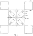
- FIG. 14 is a view of wire inspection system 700 from an exemplary vantage point 202.
- wire inspection system 700 includes array 402 of mirrors 214.
- a third mirror 702 in array 402 includes reflective face 704 having a truncated rhomboid-shaped profile such that the second reflection from second plurality 406 of mirrors 214 is visible between adjacent third mirrors 702 in first plurality 404 when viewed from vantage point 202.
- third mirrors 702 when compared to third mirrors 414, third mirrors 702 have a narrower profile such that portions of reflective face 602 of third mirrors 414 that do not show useful information about first inspection zone 228 are removed.
- removing the portions of third mirrors 414 to form third mirrors 702 enables the reflection from second plurality 406 of mirrors 214 to be substantially unobstructed when viewed from vantage point 202.
- the number of pixels in a pixel array (not shown) in an image captured by visual imaging device 206 that provide a full view of wire segment 210 in a reflection from the arrays described herein varies between wire inspection systems 200-700.
- the number of pixels required to provide a full view of wire segment 210 reduces in size as the implementations described herein progress from wire inspection system 200 to wire inspection system 700.
- visual imaging device 206 may be in any orientation relative to viewing apparatus 204 that enables the pixel array to be reduced in size.
- a method of inspecting a wire segment includes positioning wire segment 210 within guide tube 208, orienting mirrors 214 in an array, such as array 212, of mirrors 214 positioned about guide tube 208 such that a reflection of wire segment 210 from each mirror 214 in the array or mirrors 214 forms a full circumferential view of at least a portion of wire segment 210, and such that the reflection from each mirror 214 is within a field of view from vantage point 202.
- the method also includes determining defects in wire segment 210 from the reflection of the at least a portion of wire segment 210.
- the method further includes capturing at least one image of the reflection of wire segment 210, wherein the at least one image is captured from vantage point 202.
- the method further includes positioning the array of mirrors 214 adjacent to insertion portion 220 of guide tube 208, wherein a plurality of images of wire segment 210 in the reflection are captured at different time intervals as wire segment 210 is inserted through guide tube 208.
- orienting mirrors 214 in the array includes orienting first plurality 404 of mirrors 214 such that the image of first inspection zone 228 is in a first reflection from first plurality 404 of mirrors 214 when viewed from vantage point 202, and orienting second plurality 406 of mirrors such that the image of second inspection zone 230 is in a second reflection from second plurality 406 of mirrors 214 when viewed from vantage point 202, wherein mirrors 214 in first plurality 404 are offset from mirrors 214 in second plurality 406 relative to vantage point 202.
- the method further includes positioning first plurality 404 of mirrors 214 at a shorter distance from vantage point 202 than second plurality 406 of mirrors 214, first plurality 404 of mirrors 214 including a plurality of groups 408 of mirrors 214 spaced at regular intervals about guide tube 208, and orienting mirrors 214 in each group 408 such that a length of first optical path 242 from first inspection zone 228 to vantage point 202 is substantially similar to a length of second optical path 244 from second inspection zone 230 to vantage point 202.
Landscapes
- Physics & Mathematics (AREA)
- General Physics & Mathematics (AREA)
- General Health & Medical Sciences (AREA)
- Chemical & Material Sciences (AREA)
- Analytical Chemistry (AREA)
- Biochemistry (AREA)
- Life Sciences & Earth Sciences (AREA)
- Health & Medical Sciences (AREA)
- Immunology (AREA)
- Pathology (AREA)
- Engineering & Computer Science (AREA)
- Quality & Reliability (AREA)
- Computer Vision & Pattern Recognition (AREA)
- Theoretical Computer Science (AREA)
- Investigating Materials By The Use Of Optical Means Adapted For Particular Applications (AREA)
Priority Applications (1)
| Application Number | Priority Date | Filing Date | Title |
|---|---|---|---|
| EP20215334.2A EP3812749B1 (de) | 2015-04-07 | 2016-04-04 | Vorrichtung und verfahren zur inspektion eines drahtsegments |
Applications Claiming Priority (1)
| Application Number | Priority Date | Filing Date | Title |
|---|---|---|---|
| US14/680,293 US11333613B2 (en) | 2015-04-07 | 2015-04-07 | Apparatus and methods of inspecting a wire segment |
Related Child Applications (1)
| Application Number | Title | Priority Date | Filing Date |
|---|---|---|---|
| EP20215334.2A Division EP3812749B1 (de) | 2015-04-07 | 2016-04-04 | Vorrichtung und verfahren zur inspektion eines drahtsegments |
Publications (3)
| Publication Number | Publication Date |
|---|---|
| EP3078960A2 true EP3078960A2 (de) | 2016-10-12 |
| EP3078960A3 EP3078960A3 (de) | 2016-11-09 |
| EP3078960B1 EP3078960B1 (de) | 2020-12-23 |
Family
ID=55752163
Family Applications (2)
| Application Number | Title | Priority Date | Filing Date |
|---|---|---|---|
| EP20215334.2A Active EP3812749B1 (de) | 2015-04-07 | 2016-04-04 | Vorrichtung und verfahren zur inspektion eines drahtsegments |
| EP16163687.3A Active EP3078960B1 (de) | 2015-04-07 | 2016-04-04 | Vorrichtung und verfahren zur inspektion eines drahtsegments |
Family Applications Before (1)
| Application Number | Title | Priority Date | Filing Date |
|---|---|---|---|
| EP20215334.2A Active EP3812749B1 (de) | 2015-04-07 | 2016-04-04 | Vorrichtung und verfahren zur inspektion eines drahtsegments |
Country Status (5)
| Country | Link |
|---|---|
| US (2) | US11333613B2 (de) |
| EP (2) | EP3812749B1 (de) |
| JP (2) | JP7039161B2 (de) |
| BR (1) | BR102016001871B1 (de) |
| ES (1) | ES2984711T3 (de) |
Cited By (1)
| Publication number | Priority date | Publication date | Assignee | Title |
|---|---|---|---|---|
| EP4092407A1 (de) * | 2021-05-04 | 2022-11-23 | H & T Marsberg GmbH & Co. KG | Inspektionsvorrichtung zur inspektion von zylindrischen metallformteilen |
Families Citing this family (3)
| Publication number | Priority date | Publication date | Assignee | Title |
|---|---|---|---|---|
| RS67113B1 (sr) * | 2018-08-13 | 2025-09-30 | Komax Holding Ag | Ispitni uređaj za ispitivanje kraja kabla i postupak za čišćenje ogledala ispitnog uređaja |
| TWI838665B (zh) * | 2021-12-09 | 2024-04-11 | 唐虞企業股份有限公司 | 電連接器 |
| CN118593868B (zh) * | 2024-08-08 | 2024-10-11 | 四川省医学科学院·四川省人民医院 | 一种可视化女性自用一次性导尿装置 |
Family Cites Families (51)
| Publication number | Priority date | Publication date | Assignee | Title |
|---|---|---|---|---|
| CH615516A5 (de) * | 1977-01-26 | 1980-01-31 | Idf Co Ltd | |
| US4358202A (en) * | 1980-07-28 | 1982-11-09 | Essex Group, Inc. | Apparatus and method for monitoring the surface character of circular objects |
| JPS5895911A (ja) | 1981-12-01 | 1983-06-07 | 新明和工業株式会社 | ワイヤ端末処理装置 |
| US4649621A (en) * | 1986-02-21 | 1987-03-17 | Artos Engineering Company | Wire processing apparatus having control means |
| DE3729819A1 (de) * | 1987-09-05 | 1989-03-16 | Spectrospin Ag | Magnetanordnung fuer nmr-spektrometer |
| US4988875A (en) * | 1988-12-13 | 1991-01-29 | At&T Bell Laboratories | Near infrared polyethylene inspection system and method |
| US5050093A (en) | 1989-10-19 | 1991-09-17 | The Boeing Company | Method and apparatus for inspecting electrical wire |
| JP2942487B2 (ja) | 1995-10-24 | 1999-08-30 | シーケーディ株式会社 | 外観検査装置 |
| US7257878B2 (en) * | 1995-11-06 | 2007-08-21 | Beat Locher | Continuous cable processing apparatus |
| US5936725A (en) * | 1997-10-28 | 1999-08-10 | Materials Technologies Corp. | Apparatus and method for viewing and inspecting a circumferential surface area of a test object |
| IT1299859B1 (it) | 1998-02-23 | 2000-04-04 | Gd Spa | Unita' elettro-ottica di rilevamento dell'intera superficie lateale di articoli di forma sostanzialmente cilindrica. |
| US6088609A (en) * | 1998-06-30 | 2000-07-11 | Larison, Ii; Wayne A. | Apparatus and method for monitoring a fetus |
| JP2000018927A (ja) | 1998-07-02 | 2000-01-21 | Oita Nippon Denki Kk | 外観検査装置 |
| US6217006B1 (en) * | 1998-07-15 | 2001-04-17 | James J. Muller | Closed ended tubular safety device and method |
| JP3488100B2 (ja) * | 1998-10-13 | 2004-01-19 | 矢崎総業株式会社 | 自動切断圧着装置 |
| US6169600B1 (en) * | 1998-11-20 | 2001-01-02 | Acuity Imaging, Llc | Cylindrical object surface inspection system |
| US6512536B1 (en) * | 1999-02-09 | 2003-01-28 | The United States Of America As Represented By The United States National Aeronautics And Space Administration | Cable and line inspection mechanism |
| JP4361156B2 (ja) * | 1999-02-22 | 2009-11-11 | 三菱重工食品包装機械株式会社 | 物品の外観検査装置 |
| US6213128B1 (en) * | 1999-06-04 | 2001-04-10 | Philip Morris Incorporated | Apparatus and method for making and inspecting multi-component wrapped article |
| FI111101B (fi) | 1999-09-29 | 2003-05-30 | Nextrom Holding Sa | Menetelmä pitkänomaisen elementin urien geometrian mittaamiseksi |
| US6728453B2 (en) * | 2001-06-27 | 2004-04-27 | Pirelli Communications Cables And Systems Usa, Llc | Method of determining lay length of S-Z stranded buffer tubes in optical fiber cable during manufacturing |
| JP2003215081A (ja) * | 2002-01-24 | 2003-07-30 | Central Glass Co Ltd | 板ガラスに形成された導電線の断線検査方法およびその装置 |
| AU2003253235A1 (en) * | 2002-08-19 | 2004-03-03 | Green Vision Systems Ltd. | Electro-optically inspecting a longitudinally moving rod of material |
| US20050117211A1 (en) | 2003-12-02 | 2005-06-02 | Cotterill John S. | Method of marking a piece of material |
| ATE484624T1 (de) * | 2004-06-29 | 2010-10-15 | Sgl Carbon Se | Rotorbügel für drahtverlitzungs- oder drahtverseilmaschinen |
| WO2006027855A1 (ja) * | 2004-09-10 | 2006-03-16 | Hitachi, Ltd. | 表示装置及び撮像装置 |
| WO2009007447A2 (en) * | 2007-07-11 | 2009-01-15 | Universite Libre De Bruxelles | Deformable mirror |
| WO2009074161A1 (en) * | 2007-12-10 | 2009-06-18 | Carl Zeiss Surgical Gmbh | Head-mountable loupe |
| US20090208053A1 (en) * | 2008-02-19 | 2009-08-20 | Benjamin Kent | Automatic identification and removal of objects in an image, such as wires in a frame of video |
| FR2928898B1 (fr) * | 2008-03-21 | 2010-04-16 | Saipem Sa | Support flottant comprenant un touret equipe d'une bouee d'amarrage de conduites de liaison fond/surface deconnectable |
| CA2762545C (en) * | 2008-05-23 | 2016-10-04 | Martin C. Tilley | Cable transport system |
| FR2935679B1 (fr) * | 2008-09-05 | 2010-09-24 | Saipem Sa | Support flottant comprenant un touret equipe de deux bouees d'amarrage de lignes d'ancrage et de conduites de liaison fond/surface |
| WO2010092619A1 (en) | 2009-02-12 | 2010-08-19 | Otis Elevator Company | Elevator tension member image inspection device |
| GB0917688D0 (en) * | 2009-10-09 | 2009-11-25 | Ucl Business Plc | Tomosynthesis apparatus and method |
| JP5356202B2 (ja) | 2009-12-09 | 2013-12-04 | 新明和工業株式会社 | 被覆電線検査装置及びこれを備えた電線処理機 |
| DE102011003140A1 (de) * | 2011-01-25 | 2012-07-26 | Hamilton Bonaduz Ag | Optisches Analyseverfahren für Flüssigkeit in einem Probenbehälter und Analyseeinrichtung zur Durchführung des Verfahrens |
| AT510849B1 (de) | 2011-06-28 | 2012-07-15 | Medek & Schoerner Gmbh | Vorrichtung zur optischen erfassung von objekten |
| US10226185B2 (en) * | 2012-05-03 | 2019-03-12 | St. Jude Medical Coordination Center Bvba | Tube and sensor guide wire comprising tube |
| JP6093527B2 (ja) | 2012-09-14 | 2017-03-08 | リコーエレメックス株式会社 | 検査装置 |
| JP5739503B2 (ja) * | 2012-11-19 | 2015-06-24 | 日本特殊陶業株式会社 | スパークプラグの検査方法及びスパークプラグの製造方法 |
| JP5567239B1 (ja) * | 2013-02-23 | 2014-08-06 | 古河電気工業株式会社 | 接続構造体の製造方法、及び接続構造体の製造装置 |
| US9665932B2 (en) * | 2013-09-03 | 2017-05-30 | Thales Transport & Security, Inc. | Camera based cable inspection system |
| US9437401B2 (en) * | 2013-12-20 | 2016-09-06 | Plasmology4, Inc. | System and method for plasma treatment using directional dielectric barrier discharge energy system |
| JP6398060B2 (ja) * | 2013-12-27 | 2018-10-03 | アドバンストマテリアルテクノロジーズ株式会社 | 熱ポーリング方法、圧電体膜の製造方法、及び圧電特性の検査方法 |
| KR101617772B1 (ko) * | 2014-02-21 | 2016-05-03 | 선문대학교 산학협력단 | 검사 장치 |
| US20170075102A1 (en) * | 2014-03-05 | 2017-03-16 | The Chugoku Electric Power Co., Inc. | Guide tube for guiding cable of internal observation device and cable guiding method |
| US10593036B2 (en) * | 2014-03-12 | 2020-03-17 | Livestock Improvement Association Of Japan, Inc. | Sperm inspection method and device |
| WO2015151202A1 (ja) * | 2014-03-31 | 2015-10-08 | 三菱電機株式会社 | 電動機、送風機及び圧縮機 |
| US20150336767A1 (en) * | 2014-05-21 | 2015-11-26 | Tyco Electronics Corporation | Wire guidance system |
| US9461013B2 (en) * | 2014-11-21 | 2016-10-04 | Asm Technology Singapore Pte Ltd | Wire spool system for a wire bonding apparatus |
| US9749013B2 (en) * | 2015-03-17 | 2017-08-29 | At&T Intellectual Property I, L.P. | Method and apparatus for reducing attenuation of electromagnetic waves guided by a transmission medium |
-
2015
- 2015-04-07 US US14/680,293 patent/US11333613B2/en active Active
-
2016
- 2016-01-28 BR BR102016001871-4A patent/BR102016001871B1/pt active IP Right Grant
- 2016-04-04 ES ES20215334T patent/ES2984711T3/es active Active
- 2016-04-04 EP EP20215334.2A patent/EP3812749B1/de active Active
- 2016-04-04 EP EP16163687.3A patent/EP3078960B1/de active Active
- 2016-04-05 JP JP2016075600A patent/JP7039161B2/ja active Active
-
2022
- 2022-03-09 JP JP2022035842A patent/JP7606998B2/ja active Active
- 2022-04-21 US US17/725,767 patent/US11933736B2/en active Active
Non-Patent Citations (1)
| Title |
|---|
| None |
Cited By (1)
| Publication number | Priority date | Publication date | Assignee | Title |
|---|---|---|---|---|
| EP4092407A1 (de) * | 2021-05-04 | 2022-11-23 | H & T Marsberg GmbH & Co. KG | Inspektionsvorrichtung zur inspektion von zylindrischen metallformteilen |
Also Published As
| Publication number | Publication date |
|---|---|
| JP7606998B2 (ja) | 2024-12-26 |
| US11333613B2 (en) | 2022-05-17 |
| BR102016001871A2 (pt) | 2016-10-11 |
| JP2022084721A (ja) | 2022-06-07 |
| EP3812749A1 (de) | 2021-04-28 |
| EP3078960B1 (de) | 2020-12-23 |
| JP2016212088A (ja) | 2016-12-15 |
| EP3812749B1 (de) | 2024-06-05 |
| ES2984711T3 (es) | 2024-10-30 |
| JP7039161B2 (ja) | 2022-03-22 |
| EP3078960A3 (de) | 2016-11-09 |
| BR102016001871B1 (pt) | 2021-05-18 |
| US20220244190A1 (en) | 2022-08-04 |
| US11933736B2 (en) | 2024-03-19 |
| US20160299086A1 (en) | 2016-10-13 |
Similar Documents
| Publication | Publication Date | Title |
|---|---|---|
| US11933736B2 (en) | Apparatus and methods of inspecting a wire segment | |
| EP3109624B1 (de) | Systeme und verfahren zur automatischen prüfung von drahtsegmenten | |
| EP2897100B1 (de) | System und Verfahren zur Inspektion eines Objekts | |
| US8983172B2 (en) | Visual inspection apparatus, secure one-way data transfer device and methods therefor | |
| US20130113915A1 (en) | Method and System for Position Control Based on Automated Defect Detection Feedback | |
| US10810728B2 (en) | Method for using a vision system to evaluate shield trims on shielded cables | |
| JP5714627B2 (ja) | 円筒体検査装置 | |
| US20160185469A1 (en) | Method and system for aircraft appearance inspection | |
| DE102009017786B3 (de) | Verfahren zur Detektion von Fehlstellen in einer dünnen Waferscheibe für ein Solarelement sowie Vorrichtung zur Durchführung des Verfahrens | |
| CN104597907A (zh) | 一种架空输电线路无人机巡检系统飞行准确性评价方法 | |
| DE102020207961B4 (de) | Vorrichtung zur Prüfung des Erscheinungsbilds eines Anschlusses | |
| US20220244303A1 (en) | Method for ascertaining and depicting potential damaged areas on components of overhead cables | |
| EP3276131A1 (de) | Systeme und verfahren zur indexierung und erkennung von komponenten | |
| CN103718024B (zh) | 平板玻璃检查装置、平板玻璃检查方法、平板玻璃制造装置以及平板玻璃制造方法 | |
| CN116778357A (zh) | 利用可见光缺陷识别的电力线路无人机巡检方法和系统 | |
| US20190128666A1 (en) | Systems and methods for gathering data and information on surface characteristics of an object | |
| EP2853856A1 (de) | Verfahren und Vorrichtung zur optischen Untersuchung einer Oberfläche eines Körpers | |
| US20160103025A1 (en) | Tool and method for use in measuring a pressure induced by a biasing member on a surface | |
| CN117330572B (zh) | 一种线束用智能化电测台 | |
| CN110779486B (zh) | 一种用于电缆导体检测的误差修正方法及系统 | |
| CN118505697A (zh) | 自适应瓶盖检验方法 | |
| CN118310965A (zh) | 一种视觉检测复检定位方法、装置、设备及存储介质 |
Legal Events
| Date | Code | Title | Description |
|---|---|---|---|
| PUAI | Public reference made under article 153(3) epc to a published international application that has entered the european phase |
Free format text: ORIGINAL CODE: 0009012 |
|
| PUAL | Search report despatched |
Free format text: ORIGINAL CODE: 0009013 |
|
| 17P | Request for examination filed |
Effective date: 20160404 |
|
| AK | Designated contracting states |
Kind code of ref document: A2 Designated state(s): AL AT BE BG CH CY CZ DE DK EE ES FI FR GB GR HR HU IE IS IT LI LT LU LV MC MK MT NL NO PL PT RO RS SE SI SK SM TR |
|
| AX | Request for extension of the european patent |
Extension state: BA ME |
|
| AK | Designated contracting states |
Kind code of ref document: A3 Designated state(s): AL AT BE BG CH CY CZ DE DK EE ES FI FR GB GR HR HU IE IS IT LI LT LU LV MC MK MT NL NO PL PT RO RS SE SI SK SM TR |
|
| AX | Request for extension of the european patent |
Extension state: BA ME |
|
| RIC1 | Information provided on ipc code assigned before grant |
Ipc: G01N 21/952 20060101AFI20161006BHEP |
|
| RBV | Designated contracting states (corrected) |
Designated state(s): AL AT BE BG CH CY CZ DE DK EE ES FI FR GB GR HR HU IE IS IT LI LT LU LV MC MK MT NL NO PL PT RO RS SE SI SK SM TR |
|
| STAA | Information on the status of an ep patent application or granted ep patent |
Free format text: STATUS: EXAMINATION IS IN PROGRESS |
|
| 17Q | First examination report despatched |
Effective date: 20190828 |
|
| GRAP | Despatch of communication of intention to grant a patent |
Free format text: ORIGINAL CODE: EPIDOSNIGR1 |
|
| STAA | Information on the status of an ep patent application or granted ep patent |
Free format text: STATUS: GRANT OF PATENT IS INTENDED |
|
| INTG | Intention to grant announced |
Effective date: 20200504 |
|
| GRAJ | Information related to disapproval of communication of intention to grant by the applicant or resumption of examination proceedings by the epo deleted |
Free format text: ORIGINAL CODE: EPIDOSDIGR1 |
|
| STAA | Information on the status of an ep patent application or granted ep patent |
Free format text: STATUS: EXAMINATION IS IN PROGRESS |
|
| INTC | Intention to grant announced (deleted) | ||
| GRAR | Information related to intention to grant a patent recorded |
Free format text: ORIGINAL CODE: EPIDOSNIGR71 |
|
| GRAS | Grant fee paid |
Free format text: ORIGINAL CODE: EPIDOSNIGR3 |
|
| STAA | Information on the status of an ep patent application or granted ep patent |
Free format text: STATUS: GRANT OF PATENT IS INTENDED |
|
| GRAA | (expected) grant |
Free format text: ORIGINAL CODE: 0009210 |
|
| STAA | Information on the status of an ep patent application or granted ep patent |
Free format text: STATUS: THE PATENT HAS BEEN GRANTED |
|
| INTG | Intention to grant announced |
Effective date: 20201111 |
|
| AK | Designated contracting states |
Kind code of ref document: B1 Designated state(s): AL AT BE BG CH CY CZ DE DK EE ES FI FR GB GR HR HU IE IS IT LI LT LU LV MC MK MT NL NO PL PT RO RS SE SI SK SM TR |
|
| REG | Reference to a national code |
Ref country code: GB Ref legal event code: FG4D |
|
| REG | Reference to a national code |
Ref country code: DE Ref legal event code: R096 Ref document number: 602016050115 Country of ref document: DE |
|
| REG | Reference to a national code |
Ref country code: AT Ref legal event code: REF Ref document number: 1348208 Country of ref document: AT Kind code of ref document: T Effective date: 20210115 |
|
| REG | Reference to a national code |
Ref country code: IE Ref legal event code: FG4D |
|
| PG25 | Lapsed in a contracting state [announced via postgrant information from national office to epo] |
Ref country code: NO Free format text: LAPSE BECAUSE OF FAILURE TO SUBMIT A TRANSLATION OF THE DESCRIPTION OR TO PAY THE FEE WITHIN THE PRESCRIBED TIME-LIMIT Effective date: 20210323 Ref country code: RS Free format text: LAPSE BECAUSE OF FAILURE TO SUBMIT A TRANSLATION OF THE DESCRIPTION OR TO PAY THE FEE WITHIN THE PRESCRIBED TIME-LIMIT Effective date: 20201223 Ref country code: FI Free format text: LAPSE BECAUSE OF FAILURE TO SUBMIT A TRANSLATION OF THE DESCRIPTION OR TO PAY THE FEE WITHIN THE PRESCRIBED TIME-LIMIT Effective date: 20201223 Ref country code: GR Free format text: LAPSE BECAUSE OF FAILURE TO SUBMIT A TRANSLATION OF THE DESCRIPTION OR TO PAY THE FEE WITHIN THE PRESCRIBED TIME-LIMIT Effective date: 20210324 |
|
| REG | Reference to a national code |
Ref country code: AT Ref legal event code: MK05 Ref document number: 1348208 Country of ref document: AT Kind code of ref document: T Effective date: 20201223 |
|
| REG | Reference to a national code |
Ref country code: NL Ref legal event code: MP Effective date: 20201223 |
|
| PG25 | Lapsed in a contracting state [announced via postgrant information from national office to epo] |
Ref country code: SE Free format text: LAPSE BECAUSE OF FAILURE TO SUBMIT A TRANSLATION OF THE DESCRIPTION OR TO PAY THE FEE WITHIN THE PRESCRIBED TIME-LIMIT Effective date: 20201223 Ref country code: LV Free format text: LAPSE BECAUSE OF FAILURE TO SUBMIT A TRANSLATION OF THE DESCRIPTION OR TO PAY THE FEE WITHIN THE PRESCRIBED TIME-LIMIT Effective date: 20201223 Ref country code: BG Free format text: LAPSE BECAUSE OF FAILURE TO SUBMIT A TRANSLATION OF THE DESCRIPTION OR TO PAY THE FEE WITHIN THE PRESCRIBED TIME-LIMIT Effective date: 20210323 |
|
| PG25 | Lapsed in a contracting state [announced via postgrant information from national office to epo] |
Ref country code: NL Free format text: LAPSE BECAUSE OF FAILURE TO SUBMIT A TRANSLATION OF THE DESCRIPTION OR TO PAY THE FEE WITHIN THE PRESCRIBED TIME-LIMIT Effective date: 20201223 Ref country code: HR Free format text: LAPSE BECAUSE OF FAILURE TO SUBMIT A TRANSLATION OF THE DESCRIPTION OR TO PAY THE FEE WITHIN THE PRESCRIBED TIME-LIMIT Effective date: 20201223 |
|
| REG | Reference to a national code |
Ref country code: LT Ref legal event code: MG9D |
|
| PG25 | Lapsed in a contracting state [announced via postgrant information from national office to epo] |
Ref country code: RO Free format text: LAPSE BECAUSE OF FAILURE TO SUBMIT A TRANSLATION OF THE DESCRIPTION OR TO PAY THE FEE WITHIN THE PRESCRIBED TIME-LIMIT Effective date: 20201223 Ref country code: PT Free format text: LAPSE BECAUSE OF FAILURE TO SUBMIT A TRANSLATION OF THE DESCRIPTION OR TO PAY THE FEE WITHIN THE PRESCRIBED TIME-LIMIT Effective date: 20210423 Ref country code: SK Free format text: LAPSE BECAUSE OF FAILURE TO SUBMIT A TRANSLATION OF THE DESCRIPTION OR TO PAY THE FEE WITHIN THE PRESCRIBED TIME-LIMIT Effective date: 20201223 Ref country code: CZ Free format text: LAPSE BECAUSE OF FAILURE TO SUBMIT A TRANSLATION OF THE DESCRIPTION OR TO PAY THE FEE WITHIN THE PRESCRIBED TIME-LIMIT Effective date: 20201223 Ref country code: EE Free format text: LAPSE BECAUSE OF FAILURE TO SUBMIT A TRANSLATION OF THE DESCRIPTION OR TO PAY THE FEE WITHIN THE PRESCRIBED TIME-LIMIT Effective date: 20201223 Ref country code: LT Free format text: LAPSE BECAUSE OF FAILURE TO SUBMIT A TRANSLATION OF THE DESCRIPTION OR TO PAY THE FEE WITHIN THE PRESCRIBED TIME-LIMIT Effective date: 20201223 Ref country code: SM Free format text: LAPSE BECAUSE OF FAILURE TO SUBMIT A TRANSLATION OF THE DESCRIPTION OR TO PAY THE FEE WITHIN THE PRESCRIBED TIME-LIMIT Effective date: 20201223 |
|
| PG25 | Lapsed in a contracting state [announced via postgrant information from national office to epo] |
Ref country code: AT Free format text: LAPSE BECAUSE OF FAILURE TO SUBMIT A TRANSLATION OF THE DESCRIPTION OR TO PAY THE FEE WITHIN THE PRESCRIBED TIME-LIMIT Effective date: 20201223 Ref country code: PL Free format text: LAPSE BECAUSE OF FAILURE TO SUBMIT A TRANSLATION OF THE DESCRIPTION OR TO PAY THE FEE WITHIN THE PRESCRIBED TIME-LIMIT Effective date: 20201223 |
|
| REG | Reference to a national code |
Ref country code: DE Ref legal event code: R097 Ref document number: 602016050115 Country of ref document: DE |
|
| PG25 | Lapsed in a contracting state [announced via postgrant information from national office to epo] |
Ref country code: IS Free format text: LAPSE BECAUSE OF FAILURE TO SUBMIT A TRANSLATION OF THE DESCRIPTION OR TO PAY THE FEE WITHIN THE PRESCRIBED TIME-LIMIT Effective date: 20210423 |
|
| PG25 | Lapsed in a contracting state [announced via postgrant information from national office to epo] |
Ref country code: AL Free format text: LAPSE BECAUSE OF FAILURE TO SUBMIT A TRANSLATION OF THE DESCRIPTION OR TO PAY THE FEE WITHIN THE PRESCRIBED TIME-LIMIT Effective date: 20201223 Ref country code: IT Free format text: LAPSE BECAUSE OF FAILURE TO SUBMIT A TRANSLATION OF THE DESCRIPTION OR TO PAY THE FEE WITHIN THE PRESCRIBED TIME-LIMIT Effective date: 20201223 |
|
| PLBE | No opposition filed within time limit |
Free format text: ORIGINAL CODE: 0009261 |
|
| STAA | Information on the status of an ep patent application or granted ep patent |
Free format text: STATUS: NO OPPOSITION FILED WITHIN TIME LIMIT |
|
| PG25 | Lapsed in a contracting state [announced via postgrant information from national office to epo] |
Ref country code: ES Free format text: LAPSE BECAUSE OF FAILURE TO SUBMIT A TRANSLATION OF THE DESCRIPTION OR TO PAY THE FEE WITHIN THE PRESCRIBED TIME-LIMIT Effective date: 20201223 Ref country code: DK Free format text: LAPSE BECAUSE OF FAILURE TO SUBMIT A TRANSLATION OF THE DESCRIPTION OR TO PAY THE FEE WITHIN THE PRESCRIBED TIME-LIMIT Effective date: 20201223 Ref country code: MC Free format text: LAPSE BECAUSE OF FAILURE TO SUBMIT A TRANSLATION OF THE DESCRIPTION OR TO PAY THE FEE WITHIN THE PRESCRIBED TIME-LIMIT Effective date: 20201223 |
|
| 26N | No opposition filed |
Effective date: 20210924 |
|
| PG25 | Lapsed in a contracting state [announced via postgrant information from national office to epo] |
Ref country code: LU Free format text: LAPSE BECAUSE OF NON-PAYMENT OF DUE FEES Effective date: 20210404 |
|
| REG | Reference to a national code |
Ref country code: BE Ref legal event code: MM Effective date: 20210430 |
|
| PG25 | Lapsed in a contracting state [announced via postgrant information from national office to epo] |
Ref country code: CH Free format text: LAPSE BECAUSE OF NON-PAYMENT OF DUE FEES Effective date: 20210430 Ref country code: LI Free format text: LAPSE BECAUSE OF NON-PAYMENT OF DUE FEES Effective date: 20210430 |
|
| PG25 | Lapsed in a contracting state [announced via postgrant information from national office to epo] |
Ref country code: SI Free format text: LAPSE BECAUSE OF FAILURE TO SUBMIT A TRANSLATION OF THE DESCRIPTION OR TO PAY THE FEE WITHIN THE PRESCRIBED TIME-LIMIT Effective date: 20201223 |
|
| PG25 | Lapsed in a contracting state [announced via postgrant information from national office to epo] |
Ref country code: IE Free format text: LAPSE BECAUSE OF NON-PAYMENT OF DUE FEES Effective date: 20210404 |
|
| PG25 | Lapsed in a contracting state [announced via postgrant information from national office to epo] |
Ref country code: IS Free format text: LAPSE BECAUSE OF FAILURE TO SUBMIT A TRANSLATION OF THE DESCRIPTION OR TO PAY THE FEE WITHIN THE PRESCRIBED TIME-LIMIT Effective date: 20210423 |
|
| PG25 | Lapsed in a contracting state [announced via postgrant information from national office to epo] |
Ref country code: BE Free format text: LAPSE BECAUSE OF NON-PAYMENT OF DUE FEES Effective date: 20210430 |
|
| PG25 | Lapsed in a contracting state [announced via postgrant information from national office to epo] |
Ref country code: HU Free format text: LAPSE BECAUSE OF FAILURE TO SUBMIT A TRANSLATION OF THE DESCRIPTION OR TO PAY THE FEE WITHIN THE PRESCRIBED TIME-LIMIT; INVALID AB INITIO Effective date: 20160404 |
|
| P01 | Opt-out of the competence of the unified patent court (upc) registered |
Effective date: 20230516 |
|
| PG25 | Lapsed in a contracting state [announced via postgrant information from national office to epo] |
Ref country code: CY Free format text: LAPSE BECAUSE OF FAILURE TO SUBMIT A TRANSLATION OF THE DESCRIPTION OR TO PAY THE FEE WITHIN THE PRESCRIBED TIME-LIMIT Effective date: 20201223 |
|
| PG25 | Lapsed in a contracting state [announced via postgrant information from national office to epo] |
Ref country code: MK Free format text: LAPSE BECAUSE OF FAILURE TO SUBMIT A TRANSLATION OF THE DESCRIPTION OR TO PAY THE FEE WITHIN THE PRESCRIBED TIME-LIMIT Effective date: 20201223 |
|
| PG25 | Lapsed in a contracting state [announced via postgrant information from national office to epo] |
Ref country code: TR Free format text: LAPSE BECAUSE OF FAILURE TO SUBMIT A TRANSLATION OF THE DESCRIPTION OR TO PAY THE FEE WITHIN THE PRESCRIBED TIME-LIMIT Effective date: 20201223 |
|
| PG25 | Lapsed in a contracting state [announced via postgrant information from national office to epo] |
Ref country code: MT Free format text: LAPSE BECAUSE OF FAILURE TO SUBMIT A TRANSLATION OF THE DESCRIPTION OR TO PAY THE FEE WITHIN THE PRESCRIBED TIME-LIMIT Effective date: 20201223 |
|
| PGFP | Annual fee paid to national office [announced via postgrant information from national office to epo] |
Ref country code: DE Payment date: 20250429 Year of fee payment: 10 |
|
| PGFP | Annual fee paid to national office [announced via postgrant information from national office to epo] |
Ref country code: GB Payment date: 20250428 Year of fee payment: 10 |
|
| PGFP | Annual fee paid to national office [announced via postgrant information from national office to epo] |
Ref country code: FR Payment date: 20250425 Year of fee payment: 10 |