EP3081868A1 - Ensemble et procédé d'assemblage d'une unité de source de chaleur d'un conditionneur d'air au niveau du site du conditionneur d'air - Google Patents
Ensemble et procédé d'assemblage d'une unité de source de chaleur d'un conditionneur d'air au niveau du site du conditionneur d'air Download PDFInfo
- Publication number
- EP3081868A1 EP3081868A1 EP15164038.0A EP15164038A EP3081868A1 EP 3081868 A1 EP3081868 A1 EP 3081868A1 EP 15164038 A EP15164038 A EP 15164038A EP 3081868 A1 EP3081868 A1 EP 3081868A1
- Authority
- EP
- European Patent Office
- Prior art keywords
- heat source
- heat exchanger
- air conditioner
- compressor
- modules
- Prior art date
- Legal status (The legal status is an assumption and is not a legal conclusion. Google has not performed a legal analysis and makes no representation as to the accuracy of the status listed.)
- Granted
Links
Images

Classifications
-
- F—MECHANICAL ENGINEERING; LIGHTING; HEATING; WEAPONS; BLASTING
- F24—HEATING; RANGES; VENTILATING
- F24F—AIR-CONDITIONING; AIR-HUMIDIFICATION; VENTILATION; USE OF AIR CURRENTS FOR SCREENING
- F24F1/00—Room units for air-conditioning, e.g. separate or self-contained units or units receiving primary air from a central station
- F24F1/0003—Room units for air-conditioning, e.g. separate or self-contained units or units receiving primary air from a central station characterised by a split arrangement, wherein parts of the air-conditioning system, e.g. evaporator and condenser, are in separately located units
-
- F—MECHANICAL ENGINEERING; LIGHTING; HEATING; WEAPONS; BLASTING
- F24—HEATING; RANGES; VENTILATING
- F24F—AIR-CONDITIONING; AIR-HUMIDIFICATION; VENTILATION; USE OF AIR CURRENTS FOR SCREENING
- F24F1/00—Room units for air-conditioning, e.g. separate or self-contained units or units receiving primary air from a central station
- F24F1/02—Self-contained room units for air-conditioning, i.e. with all apparatus for treatment installed in a common casing
- F24F1/022—Self-contained room units for air-conditioning, i.e. with all apparatus for treatment installed in a common casing comprising a compressor cycle
-
- F—MECHANICAL ENGINEERING; LIGHTING; HEATING; WEAPONS; BLASTING
- F24—HEATING; RANGES; VENTILATING
- F24F—AIR-CONDITIONING; AIR-HUMIDIFICATION; VENTILATION; USE OF AIR CURRENTS FOR SCREENING
- F24F11/00—Control or safety arrangements
- F24F11/30—Control or safety arrangements for purposes related to the operation of the system, e.g. for safety or monitoring
-
- F—MECHANICAL ENGINEERING; LIGHTING; HEATING; WEAPONS; BLASTING
- F24—HEATING; RANGES; VENTILATING
- F24F—AIR-CONDITIONING; AIR-HUMIDIFICATION; VENTILATION; USE OF AIR CURRENTS FOR SCREENING
- F24F11/00—Control or safety arrangements
- F24F11/30—Control or safety arrangements for purposes related to the operation of the system, e.g. for safety or monitoring
- F24F11/46—Improving electric energy efficiency or saving
-
- F—MECHANICAL ENGINEERING; LIGHTING; HEATING; WEAPONS; BLASTING
- F24—HEATING; RANGES; VENTILATING
- F24F—AIR-CONDITIONING; AIR-HUMIDIFICATION; VENTILATION; USE OF AIR CURRENTS FOR SCREENING
- F24F11/00—Control or safety arrangements
- F24F11/62—Control or safety arrangements characterised by the type of control or by internal processing, e.g. using fuzzy logic, adaptive control or estimation of values
- F24F11/63—Electronic processing
-
- F—MECHANICAL ENGINEERING; LIGHTING; HEATING; WEAPONS; BLASTING
- F24—HEATING; RANGES; VENTILATING
- F24F—AIR-CONDITIONING; AIR-HUMIDIFICATION; VENTILATION; USE OF AIR CURRENTS FOR SCREENING
- F24F11/00—Control or safety arrangements
- F24F11/89—Arrangement or mounting of control or safety devices
-
- F—MECHANICAL ENGINEERING; LIGHTING; HEATING; WEAPONS; BLASTING
- F24—HEATING; RANGES; VENTILATING
- F24F—AIR-CONDITIONING; AIR-HUMIDIFICATION; VENTILATION; USE OF AIR CURRENTS FOR SCREENING
- F24F5/00—Air-conditioning systems or apparatus not covered by F24F1/00 or F24F3/00, e.g. using solar heat or combined with household units such as an oven or water heater
- F24F5/0007—Air-conditioning systems or apparatus not covered by F24F1/00 or F24F3/00, e.g. using solar heat or combined with household units such as an oven or water heater cooling apparatus specially adapted for use in air-conditioning
- F24F5/001—Compression cycle type
-
- F—MECHANICAL ENGINEERING; LIGHTING; HEATING; WEAPONS; BLASTING
- F24—HEATING; RANGES; VENTILATING
- F24F—AIR-CONDITIONING; AIR-HUMIDIFICATION; VENTILATION; USE OF AIR CURRENTS FOR SCREENING
- F24F2221/00—Details or features not otherwise provided for
- F24F2221/36—Modules, e.g. for an easy mounting or transport
Definitions
- the present invention relates to air-conditioners, particularly to air-conditioners of the heat pump type. More particular, the present invention relates to the assembly of a heat source unit of such air-conditioners at the site of the air conditioner.
- an air-conditioner if this type comprises an outdoor unit (heat source unit) comprising at least the compressor and the heat source heat exchanger of the air conditioner.
- outdoor unit heat source unit
- different outdoor units having different capacity and/or using different heat sources (e.g. air, water, etc.) are available.
- These outdoor units are manufactured and offered on the market by a variety of companies including Daikin ® .
- Daikin ® As the premises (e.g. a building) and, hence, the specifications for the air conditioners vary to a large extend, a plurality of different outdoor units need to be manufactured and be held available by the company's involving relatively high costs.
- the present outdoor units are relatively large and heavy so that the locations for installation of these outdoor units are very limited. Even further, in many cases, the optimum capacity and/or efficiency of the outdoor unit cannot be realized with the result of compromise with overcapacity and/or reduced efficiency of the air conditioner.
- the present invention aims at providing a set and method for assembling a heat source unit of an air conditioner at the site of the air conditioner that enables higher flexibility with respect to the installation location, to the specification such as the capacity as well as efficiency and/or to the selection of the heat source.
- the commonly used outdoor units heat source units
- a heat source heat exchanger module unit
- a compressor module unit
- the units may be placed at the same location or at different locations, indoor or outdoor.
- these modules (units) are assembled to constitute the heat source unit of an air conditioner only at the site (e.g. a building including space/-s to be conditioned) of the air conditioner and not at the manufacturing site.
- different modules (units) and/or different number of modules (units) may be combined to meet the required specifications (e.g. of the space/-s to be conditioned in a building).
- the required specifications may be met more closely and the heat source unit may be adapted to the required capacity with high-efficiency.
- a set for assembling a heat source unit of an air conditioner at the site of the air conditioner comprises a heat source heat exchanger module and a compressor module.
- the heat source heat exchanger module has a first casing, a heat source heat exchanger being disposed in the first casing.
- the heat source heat exchanger module comprises two compressor module ports preferably accessible from the outside of the first casing and fluidly communicated with the heat source heat exchanger, preferably via refrigerant piping.
- the heat source heat exchanger module comprises an indoor unit port instead of one of the compressor module ports for direct connection of one or more indoor units.
- the compressor module has a second casing separate from the first casing. "Separate” in this context means that the casings represent separate assemblies or units and should not encompass that one casing is disposed within the other casing. Further, the compressor module comprises a compressor disposed in the second casing.
- two heat source heat exchanger module ports are provided and preferably accessible from the outside of the second casing.
- a first heat source heat exchanger module port is fluidly communicated with the compressor again preferably by refrigerant piping.
- two indoor unit ports are provided which are preferably also accessible from the outside of the second casing.
- One of the indoor unit ports (first indoor unit port) will be communicated with the second heat source heat exchanger module port by refrigerant piping.
- the other of the indoor unit ports (second indoor unit port) will be fluidly connected to the compressor preferably by refrigerant piping.
- connection between the heat source heat exchanger module and the at least one indoor unit may be looped through the second casing by connecting the heat source heat exchanger module to the second heat source heat exchanger module port and the one or more indoor units to the first indoor unit port which are fluidly connected by refrigerant piping.
- the compressor is fluidly connected to the heat source heat exchanger module and particularly the heat source heat exchanger using the first heat source heat exchanger module port and to the one or more indoor units using the second indoor unit port.
- the compressor module comprises one indoor unit port and one heat source heat exchanger module port.
- the indoor unit port will be fluidly communicated using a refrigerant piping to the compressor as will the one heat source heat exchanger module port.
- the compressor module and the heat source heat exchanger module may be fluidly communicated using the compressor module port(-s) and the heat source heat exchanger module port(-s) and an appropriate refrigerant piping for connecting the ports.
- the heat source heat exchanger module may either directly be connected to one or more indoor units/modules (second alternative) or via the compressor module using one of the two compressor module ports at the heat source heat exchanger module, the second heat source heat exchanger module port and the first indoor unit port and appropriate refrigerant piping for connecting the ports (first alternative).
- a main board which comprises a control logic of the air conditioner and a first electric connector.
- Each of the aforesaid modules has a circuit board wherein one of the circuit boards may be the main board. Yet, the main board may also be provided separately from the two modules.
- Each circuit board comprises a second electric connector, except for the case in which the circuit board is the main board which already comprises the first electric connector.
- the circuit boards are configured for data communication with the main board upon electrical connection of the circuit board/-s and the main board via the first and second electrical connectors.
- the circuit board of the compressor module is the main board.
- each of the modules has said circuit board.
- one of the pluralities of modules may of course comprise the main board instead of the circuit board.
- the main board is configured to automatically recognize the number and/or kind of modules connected to the main board via their circuit boards, i.e. the circuit boards of the respective modules. This provides for an easy installation according to the plug and play principle.
- the main board may comprise a switch or a plurality of switches, an input device such as a keyboard, a touchscreen or an electrical interface to for example connect an input device in order to manually adjust the number and/or kind of modules connected to the main board via their circuit boards.
- an input device such as a keyboard, a touchscreen or an electrical interface to for example connect an input device in order to manually adjust the number and/or kind of modules connected to the main board via their circuit boards.
- Another possibility may be to use dip switches and pushbuttons with seven segment or LED indicators.
- a further aspect is the method for assembling a heat source unit of an air conditioner at a site of the air conditioner using a set as described above.
- the method includes the step of selecting the number of compressor modules and heat source heat exchanger modules required to obtain the capacity and/or efficiency of the heat source unit needed for the intended air conditioner/premises. This could mean that depending on the circumstances of the premises (for example of the building and or the spaces to be conditioned, the environmental conditions) the required specifications of the air conditioner are calculated. Based on the result of the calculation, the number of the compressor modules and heat source heat exchanger modules and/or the kind of heat source heat exchanger module is selected. Subsequently, the selected modules are fluidly communicated by attaching refrigerant piping via the compressor and heat source heat exchanger ports as explained above. Even further, the circuit boards of the selected modules are electrically connected using the first and second electric connectors.
- the main board may automatically recognize the number and/or kind of selected modules as described above.
- the method may comprise the additional step of manually inputting the number and/or kind of selected modules upon electrical connection.
- Figure 1 shows a first example of an air conditioner that is assembled using a set and a method as previously described.
- the air conditioner comprises a compressor module 1 and a heat source heat exchanger module 2 which together constitute a heat source unit.
- the heat source heat exchanger module 2 is configured to use outside air as the heat source.
- the heat source heat exchanger module 2 comprises a heat exchanger 3 disposed in a casing 4 (first casing) and flown through by the outside air as indicated by the arrows in Figure 1 .
- the air flow is induced by one or more fans 24.
- the heat exchanger 3 is fluidly connected or communicated to a first and second compressor module port 6, 7 preferably accessible at the outside of the casing 4 by refrigerant piping (lines in Figure 1 connecting the heat exchanger 3 and the ports 6, 7, respectively).
- the heat source heat exchanger module 2 may further comprise a main expansion valve (not shown) of the refrigerant circuit of the air conditioner disposed in one of the lines connecting the ports 6, 7 and the heat exchanger 3, particularly the line connecting the port 7 and the heat exchanger 3. Further, a printed circuit board 5 is contained in the casing 4 having a second electrical connector (not shown).
- the compressor module 1 comprises a casing 8 (second casing) separate from the first casing 4.
- a compressor 9 is contained in the casing 8 and fluidly connected or communicated to a first heat source heat exchanger port 10 by refrigerant piping 36 via a four-way valve 38.
- the 4-way valve 38 of the refrigerant circuit serves to switch between the cooling and heating operation of the air conditioner if desired or for defrosting operation.
- the compressor 9 is fluidly connected or communicated to a first indoor unit port 31 by refrigerant piping 32 via the four-way valve 38.
- a second heat source heat exchanger module port 11 is provided at the compressor module 1 and preferably accessible from the outside of the casing 8.
- the second heat source heat exchanger module port 11 is fluidly connected or communicated to a second indoor unit port 30 by refrigerant piping 37.
- Both, the first and second indoor unit ports 30, 31 are preferably provided at the casing 8 and more preferably accessible from the outside of the casing 8.
- the compressor module 1 comprises a main board 12 as its circuit board and comprising a control logic of the air conditioner.
- the main board 12 comprises a plurality of first electrical connectors (not shown).
- one indoor unit 13 is provided having a casing 14 (third casing) separate from the first and second casing 4, 8.
- the indoor unit 13 has an indoor heat exchanger 15 which is fluidly communicated to a first compressor module port 16 and a second compressor module port 17 both preferably accessible from the outside of the casing 14 by refrigerant piping 34.
- the indoor unit 13 comprises a printed circuit board 18.
- the printed circuit board 18 has a second electrical connector (not shown).
- the installer When installing the air conditioner shown in figure 1 , the installer calculates the needed capacity with the intended efficiency in mind and required for air-conditioning the premises 20 in view of the expected environmental conditions such as outdoor temperature, humidity, etc. In the present embodiment the installer then selects from a set one compressor module 1 and one heat source heat exchanger module 2 as well as one indoor unit 13 to meet the specifications resulting from the calculation.
- the heat source heat exchanger 3 and the compressor 9 are fluidly connected by means of refrigerant piping 33 using the compressor module port 6 and the heat source heat exchanger module port 10.
- the heat source heat exchanger module 2 and more particular the heat exchanger 3 is connected to the compressor module 1 using the compressor module port 7 and the heat source heat exchanger module port 11 by refrigerant piping 39.
- the indoor unit 13 is mounted in the space 21 to be conditioned.
- the indoor heat exchanger 15 of the indoor unit 13 is then fluidly communicated or connected via ports 16, 17 by refrigerant piping 23 to the indoor unit ports 30, 31 of the compressor module 1.
- the heat exchanger 3 and the indoor heat exchanger 15 are fluidly connected by means of the port 17, the refrigerant piping 23, the port 30, the refrigerant piping 37, the port 11, the refrigerant piping 39 and the port 7.
- main board 12 and the printed circuit board 5 are electrically connected by electrically connecting an electrical line (dotted line in the drawings) 22 with an electrical connector to the second electrical connector of the printed circuit board 5 and another electrical connector to the first electrical connector of the main board 12.
- the printed circuit board 18 of the indoor unit 13 is electrically connected to the main board 12 using an electrical line 35 with electrical connectors at both ends electrically connecting to the second electrical connector of the printed circuit board 18 and one of the first electrical connectors of the main board 12.
- the main board 12 Upon start of the system the main board 12 automatically recognizes the number of modules 1, 2 and 13 attached to the main board 12 and also the kind of the modules. Subsequently, the main board may select from a plurality of preinstalled programs to control the air conditioner such installed. Alternatively, the installer may input the required information and select a corresponding program via an interface.
- Figure 2 shows a second example of an air conditioner that is assembled using a set and a method as described herein.
- the difference between the embodiments in figures 1 and 2 is the use of two indoor units 13 (a first indoor unit 13 and a second indoor unit 13') in the second embodiment.
- the installer When installing the air conditioner shown in figure 2 , the installer calculates the needed capacity with the intended efficiency in mind and required for air-conditioning the premises 20 in view of the expected environmental conditions such as outdoor temperature, humidity, etc. In the present embodiment the installer then selects from a set one compressor module 1 and one heat source heat exchanger module 2 as well as two indoor units 13, 13' to meet the specifications resulting from the calculation.
- the two indoor units 13, 13' are respectively disposed in separate spaces 21, 21' to be conditioned and connected to the compressor module in parallel.
- the configuration of the second indoor unit 13' is the same as that of the first indoor unit 13' described above with respect to figure 1 , wherein the components of the second indoor unit 13' have been referred to by the same reference numerals added by "'". Hence and in order to avoid repetition the description thereof is omitted.
- the ports 16', 17' of the second indoor unit 13' are connected to the refrigerant piping 23 by refrigerant piping 23' branching off the refrigerant piping 23 and connected to the ports 16', 17', respectively.
- circuit board 18' of the second indoor unit 13' is electrically connected to the main board 12 using an electrical line 35' with electrical connectors at both ends electrically connecting to the second electrical connector of the printed circuit board 18' and one of the first electrical connectors of the main board 12.
- the system may automatically recognize the number and kind of modules or this information is manually input by the installer.
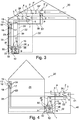
- Figure 3 shows a third example of an air conditioner that is assembled using a set and a method as described herein.
- the difference between the embodiments in figures 1 and 3 is the use of two heat source heat exchanger modules (a first heat source heat exchanger module 2 and a second heat source heat exchanger module 2') in the third embodiment.
- the installer When installing the air conditioner shown in figure 3 , the installer calculates the needed capacity with the intended efficiency in mind and required for air-conditioning the premises 20 in view of the expected environmental conditions such as outdoor temperature, humidity, etc. In the present embodiment the installer then selects from a set one compressor module 1 and two heat source heat exchanger modules 2, 2' as well as one indoor unit 13 to meet the specifications resulting from the calculation.
- the second heat source heat exchanger module 2' of the third embodiment is identical to the first heat source heat exchanger module 2 of the first embodiment.
- the two heat source heat exchanger modules 2, 2' are connected in parallel to the refrigerant circuit. More particularly, the second heat source heat exchanger module 2' is connected with the ports 6', 7' and refrigerant piping 33' and 39' to the refrigerant piping 33 and 39 of the first heat source heat exchanger module 2, respectively. Thereby the second heat source heat exchanger module 2' is fluidly communicated and connected to the compressor module 1 and the indoor unit 13 in the same manner as the first heat source heat exchanger module 2.
- circuit board 5' of the second heat source heat exchanger module 2' is electrically connected to the main board 12 using an electrical line 22' with electrical connectors at both ends electrically connecting to the second electrical connector of the printed circuit board 5' and one of the first electrical connectors of the main board 12.
- the system may automatically recognize the number and kind of modules or this information is manually input by the installer.
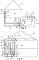
- Figures 4 and 5 show fourth and fifth examples of air conditioners that are assembled using a set and a method as described herein.
- the difference between the embodiments in figures 1 and 4 and figures 1 and 5 is the positioning of the compressor module 1 and the heat source heat exchanger module 2.
- the remainder of the embodiments as well as the electrical connection and fluid communication of the modules is the same as in the first embodiment.
- the compressor module 1 is disposed on the floor of a vehicle hall or carport 40.
- the heat source heat exchanger module 2 is disposed in the ceiling 41 of the vehicle hall or carport 40.
- the compressor module 1 is disposed in the basement of a building.
- the heat source heat exchanger module 2 is disposed in the ceiling 41 of a vehicle hall or carport 40.
- Figure 6 shows a sixth example of an air conditioner that is assembled using a set and a method as described herein.
- the difference between the embodiments in figures 1 and 6 is the use of two compressor modules (a first compressor module 1 and a second compressor module 1') in the sixth embodiment.
- the installer calculates the needed capacity with the intended efficiency in mind and required for air-conditioning the premises 20 in view of the expected environmental conditions such as outdoor temperature, humidity, etc. In the present embodiment the installer then selects from a set two compressor modules 1, 1' and one heat source heat exchanger module 2 as well as one indoor unit 13 to meet the specifications resulting from the calculation.
- the second compressor module 1' is configured identical to the first compressor module 1 as described in the first embodiment.
- the first and second compressor modules 1, 1' are connected in parallel.
- the ports 10', 11' of the second compressor module 1' are connected via refrigerant piping 33' and 39' to the refrigerant piping 33 and 39, respectively connecting the ports 10 and 11 of the first compressor module 1 to the ports 6, 7 of the heat source heat exchanger module 2.
- the ports 10', 11' of the second compressor module 1' are connected to the heat source heat exchanger module 2 in the same manner as the ports 10, 11 of the first compressor module 1.
- the ports 30' and 31' of the second compressor module 1' are connected via refrigerant piping 23' to the refrigerant piping 23 connecting the ports 30, 31 of the first compressor module 2 to the ports 16, 17 of the indoor unit 13.
- the ports 30', 31' of the second compressor module 1' are connected to the indoor unit 13 in the same manner as the first compressor module 1.
- the main board 12 of the sixth embodiment is disposed in the second compressor module 1'.
- the heat source heat exchanger module 2 or particularly its printed circuit board 5 is connected to the main board 12 via the electrical line 22 having an electrical connector at one end connecting to a second electrical connector of the printed circuit board 5 of the heat source heat exchanger module 2 and another electrical connector at the other end connecting to one of the first electrical connectors of the main board 12.
- the first compressor module 1 has a printed circuit board 5 electrically connected to the main board 12 via an electrical line 42.
- the electrical line 42 as well has an electrical connector at one and connecting to a second electrical connector of the printed circuit board 5 of the first compressor module 1 and another electrical connector at the other hand connecting to one of the first electrical connectors of the main board 12.
- the printed circuit board 18 of the indoor unit 13 is again connected to the main board 12 via an electrical line 35.
- the electrical line 35 has an electrical connector at one end connecting to a second electrical connector of the printed circuit board 18 of the indoor unit 13 and another electrical connector at the other end connecting to one of the first electrical connectors of the main board 12.
- the system may automatically recognize the number and kind of modules or this information is manually input by the installer.
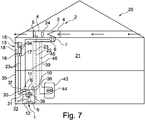
- Figure 7 shows a seventh example of an air conditioner that is assembled using a set and a method as described herein. The difference between the embodiments in figures 1 and 7 is the additional use of a domestic hot water tank 43 in the seventh embodiment.
- a hot water tank 43 comprises a refrigerant loop 44 passing through the interior of the hot water tank 43 to heat water inside the hot water tank 43 used for tap water, etc. in a domestic household.
- the refrigerant loop 44 is connected via refrigerant piping 45 and 46 to the refrigerant piping 23 and 39 connecting the compressor module 1 to the heat source heat exchanger module 2 as described earlier. Accordingly, the heat of the refrigerant flown during cooling operation via the port 10 and the refrigerant piping 23 can be transferred via the refrigerant piping 45 and the refrigerant loop 44 to the water contained in the hot water tank 43 and thereby used to heat the domestic hot water.
- the refrigerant is cooled and condensed and may subsequently be transferred via the refrigerant piping 46 to the refrigerant piping 39 and later be used for cooling the space to be conditioned via the indoor unit 13. Accordingly even more flexibility can be achieved when installing the air conditioner in the premises 20.
- the remainder of the seventh embodiment is the same as that of the first embodiment.
- any number of heat source heat exchanger modules 2 and/or compressor modules 1 and any number of indoor units 13 may be used and connected and depending on the circumstances particularly the needed capacity and the environmental conditions.
- the hot water tank 43 described in the seventh embodiment may also be incorporated in one of the previous embodiments 1 to 6.
- an electrical line may be separated into a plurality of lines connected to each other to each other.
Landscapes
- Engineering & Computer Science (AREA)
- Chemical & Material Sciences (AREA)
- Combustion & Propulsion (AREA)
- Mechanical Engineering (AREA)
- General Engineering & Computer Science (AREA)
- Signal Processing (AREA)
- Sustainable Development (AREA)
- Life Sciences & Earth Sciences (AREA)
- Physics & Mathematics (AREA)
- Fuzzy Systems (AREA)
- Mathematical Physics (AREA)
- Other Air-Conditioning Systems (AREA)
- Air Filters, Heat-Exchange Apparatuses, And Housings Of Air-Conditioning Units (AREA)
- Air Conditioning Control Device (AREA)
Priority Applications (8)
| Application Number | Priority Date | Filing Date | Title |
|---|---|---|---|
| EP15164038.0A EP3081868B1 (fr) | 2015-04-17 | 2015-04-17 | Ensemble et procédé d'assemblage d'une unité de source de chaleur d'un conditionneur d'air au niveau du site du conditionneur d'air |
| ES15164038.0T ES2638859T3 (es) | 2015-04-17 | 2015-04-17 | Conjunto y procedimiento para montar una unidad de fuente de calor de un acondicionador de aire en el sitio del acondicionador de aire |
| JP2017553278A JP7037364B2 (ja) | 2015-04-17 | 2016-04-15 | 熱源ユニットを組み立てるためのセット及び方法 |
| US15/566,995 US10344990B2 (en) | 2015-04-17 | 2016-04-15 | Set and method for assembling a heat source unit |
| BR112017021780-5A BR112017021780B1 (pt) | 2015-04-17 | 2016-04-15 | Conjunto e método para montagem de uma unidade de fonte de calor |
| AU2016249050A AU2016249050B2 (en) | 2015-04-17 | 2016-04-15 | Set and method for assembling a heat source unit |
| CN201680022301.1A CN108541298B (zh) | 2015-04-17 | 2016-04-15 | 用于组装热源单元的装置和方法 |
| PCT/JP2016/002053 WO2016166989A1 (fr) | 2015-04-17 | 2016-04-15 | Ensemble et procédé d'assemblage d'une unité de source de chaleur |
Applications Claiming Priority (1)
| Application Number | Priority Date | Filing Date | Title |
|---|---|---|---|
| EP15164038.0A EP3081868B1 (fr) | 2015-04-17 | 2015-04-17 | Ensemble et procédé d'assemblage d'une unité de source de chaleur d'un conditionneur d'air au niveau du site du conditionneur d'air |
Publications (2)
| Publication Number | Publication Date |
|---|---|
| EP3081868A1 true EP3081868A1 (fr) | 2016-10-19 |
| EP3081868B1 EP3081868B1 (fr) | 2017-08-02 |
Family
ID=52946437
Family Applications (1)
| Application Number | Title | Priority Date | Filing Date |
|---|---|---|---|
| EP15164038.0A Active EP3081868B1 (fr) | 2015-04-17 | 2015-04-17 | Ensemble et procédé d'assemblage d'une unité de source de chaleur d'un conditionneur d'air au niveau du site du conditionneur d'air |
Country Status (7)
| Country | Link |
|---|---|
| US (1) | US10344990B2 (fr) |
| EP (1) | EP3081868B1 (fr) |
| JP (1) | JP7037364B2 (fr) |
| CN (1) | CN108541298B (fr) |
| AU (1) | AU2016249050B2 (fr) |
| ES (1) | ES2638859T3 (fr) |
| WO (1) | WO2016166989A1 (fr) |
Cited By (1)
| Publication number | Priority date | Publication date | Assignee | Title |
|---|---|---|---|---|
| WO2018110385A1 (fr) * | 2016-12-12 | 2018-06-21 | ダイキン工業株式会社 | Système de climatisation |
Families Citing this family (2)
| Publication number | Priority date | Publication date | Assignee | Title |
|---|---|---|---|---|
| CN112984622A (zh) * | 2021-04-01 | 2021-06-18 | 广东积微科技有限公司 | 一种并联多联机系统排气温度的控制方法 |
| JP7332928B2 (ja) | 2021-09-30 | 2023-08-24 | ダイキン工業株式会社 | 換気装置 |
Citations (3)
| Publication number | Priority date | Publication date | Assignee | Title |
|---|---|---|---|---|
| GB828979A (en) * | 1957-06-15 | 1960-02-24 | Pellizzetti Italo | Air conditioner |
| WO2011128755A2 (fr) * | 2010-04-15 | 2011-10-20 | Thierry Schuffenecker | Dispositif thermodynamique pour chauffer et/ou climatiser un batiment |
| EP2693130A2 (fr) * | 2012-07-30 | 2014-02-05 | Fujitsu General Limited | Unité extérieure de climatiseur et climatiseur |
Family Cites Families (21)
| Publication number | Priority date | Publication date | Assignee | Title |
|---|---|---|---|---|
| JPH02275239A (ja) * | 1989-04-14 | 1990-11-09 | Sanyo Electric Co Ltd | 空気調和機 |
| JPH0486442A (ja) * | 1990-07-31 | 1992-03-19 | Toshiba Corp | 空気調和機 |
| JPH0814624A (ja) * | 1994-06-24 | 1996-01-19 | Sanyo Electric Co Ltd | 動作モード制御装置 |
| JPH10246526A (ja) * | 1997-03-07 | 1998-09-14 | Hitachi Ltd | セパレート型空気調和装置 |
| US5967761A (en) * | 1997-07-15 | 1999-10-19 | Ingersoll-Rand Company | Method for modulation lag compressor in multiple compressor system |
| JPH11248234A (ja) * | 1998-02-26 | 1999-09-14 | Hitachi Ltd | 空気調和機 |
| JP2002013763A (ja) * | 2000-04-24 | 2002-01-18 | Daikin Ind Ltd | 空気調和機の分岐ユニット |
| JP2002098394A (ja) * | 2000-09-22 | 2002-04-05 | Matsushita Seiko Co Ltd | 換気装置の制御装置 |
| CN2518012Y (zh) * | 2001-11-10 | 2002-10-23 | 向洪岗 | 高楼安装维修安全方便快捷的分体式家用空调室外机 |
| JP2005024144A (ja) * | 2003-06-30 | 2005-01-27 | Toshiba Kyaria Kk | 空気調和機 |
| JP4274984B2 (ja) * | 2004-03-22 | 2009-06-10 | 大阪瓦斯株式会社 | 分岐装置 |
| KR20080070239A (ko) * | 2007-01-25 | 2008-07-30 | 삼성전자주식회사 | 멀티 에어컨 시스템 및 그 운전 방법 |
| JP2008249269A (ja) * | 2007-03-30 | 2008-10-16 | Mitsubishi Electric Corp | 空気調和機 |
| JP5091598B2 (ja) * | 2007-09-12 | 2012-12-05 | 三洋電機株式会社 | 空気調和機の室外ユニット |
| CN201391954Y (zh) * | 2009-04-03 | 2010-01-27 | 金淞制冷设备(东莞)有限公司 | 一种小型区域用空调系统 |
| BRPI0904865A2 (pt) * | 2009-12-08 | 2011-08-02 | Whirlpool Sa | aparelho modular de ar condicionado do tipo split |
| JP5414638B2 (ja) * | 2010-08-25 | 2014-02-12 | 日立アプライアンス株式会社 | 空気調和システム |
| JP2013024505A (ja) * | 2011-07-25 | 2013-02-04 | Hitachi Appliances Inc | 冷凍サイクル装置 |
| CN103277949B (zh) * | 2013-05-24 | 2015-08-05 | 四川长虹空调有限公司 | 分流控制装置及方法、多联机空调系统和空调机 |
| CN104348783B (zh) * | 2013-07-26 | 2017-12-26 | 海尔集团公司 | 一种多联机系统内外机多种协议快速通信的方法及装置 |
| CN103953974A (zh) * | 2014-05-09 | 2014-07-30 | 华为技术有限公司 | 模块化空调 |
-
2015
- 2015-04-17 ES ES15164038.0T patent/ES2638859T3/es active Active
- 2015-04-17 EP EP15164038.0A patent/EP3081868B1/fr active Active
-
2016
- 2016-04-15 AU AU2016249050A patent/AU2016249050B2/en active Active
- 2016-04-15 CN CN201680022301.1A patent/CN108541298B/zh active Active
- 2016-04-15 WO PCT/JP2016/002053 patent/WO2016166989A1/fr not_active Ceased
- 2016-04-15 JP JP2017553278A patent/JP7037364B2/ja active Active
- 2016-04-15 US US15/566,995 patent/US10344990B2/en active Active
Patent Citations (3)
| Publication number | Priority date | Publication date | Assignee | Title |
|---|---|---|---|---|
| GB828979A (en) * | 1957-06-15 | 1960-02-24 | Pellizzetti Italo | Air conditioner |
| WO2011128755A2 (fr) * | 2010-04-15 | 2011-10-20 | Thierry Schuffenecker | Dispositif thermodynamique pour chauffer et/ou climatiser un batiment |
| EP2693130A2 (fr) * | 2012-07-30 | 2014-02-05 | Fujitsu General Limited | Unité extérieure de climatiseur et climatiseur |
Cited By (2)
| Publication number | Priority date | Publication date | Assignee | Title |
|---|---|---|---|---|
| WO2018110385A1 (fr) * | 2016-12-12 | 2018-06-21 | ダイキン工業株式会社 | Système de climatisation |
| JP2018096601A (ja) * | 2016-12-12 | 2018-06-21 | ダイキン工業株式会社 | 空気調和システム |
Also Published As
| Publication number | Publication date |
|---|---|
| BR112017021780A2 (pt) | 2018-07-10 |
| AU2016249050A1 (en) | 2017-11-23 |
| JP7037364B2 (ja) | 2022-03-16 |
| BR112017021780A8 (pt) | 2022-10-11 |
| US10344990B2 (en) | 2019-07-09 |
| EP3081868B1 (fr) | 2017-08-02 |
| WO2016166989A1 (fr) | 2016-10-20 |
| ES2638859T3 (es) | 2017-10-24 |
| JP2018511772A (ja) | 2018-04-26 |
| CN108541298B (zh) | 2021-07-13 |
| CN108541298A (zh) | 2018-09-14 |
| US20180128504A1 (en) | 2018-05-10 |
| AU2016249050B2 (en) | 2018-07-26 |
Similar Documents
| Publication | Publication Date | Title |
|---|---|---|
| US12359831B2 (en) | Systems and methods for providing custom applications for HVAC systems | |
| CN108027150B (zh) | 空气调节器 | |
| AU2014371372B2 (en) | Refrigeration device | |
| EP3096091B1 (fr) | Système de climatisation | |
| US12264842B2 (en) | Integrated zone control system | |
| EP3081868B1 (fr) | Ensemble et procédé d'assemblage d'une unité de source de chaleur d'un conditionneur d'air au niveau du site du conditionneur d'air | |
| US20250389446A1 (en) | Hvac connectivity control systems and methods | |
| EP3101351A1 (fr) | Système de régulation de température | |
| CA3017820C (fr) | Systeme de transfert de chaleur et systeme hydronique | |
| KR20080086676A (ko) | 공기 조화기 및 그 제어 방법 | |
| KR100297996B1 (ko) | 공기조화기의제어장치 | |
| JP3326999B2 (ja) | 多室空気調和機 | |
| EP2600080A2 (fr) | Procédé de vérification de position de pompe à chaleur dans un système de pompe à chaleur et système de pompe à chaleur | |
| EP2034248A1 (fr) | Système d'alimentation en eau chaude à pompe à chaleur | |
| WO2025088041A1 (fr) | Procédé de mise en service d'un système hybride | |
| BR112017021780B1 (pt) | Conjunto e método para montagem de uma unidade de fonte de calor | |
| CZ30802U1 (cs) | Systém zapojení tepelného čerpadla vzduch - voda |
Legal Events
| Date | Code | Title | Description |
|---|---|---|---|
| PUAI | Public reference made under article 153(3) epc to a published international application that has entered the european phase |
Free format text: ORIGINAL CODE: 0009012 |
|
| 17P | Request for examination filed |
Effective date: 20160425 |
|
| AK | Designated contracting states |
Kind code of ref document: A1 Designated state(s): AL AT BE BG CH CY CZ DE DK EE ES FI FR GB GR HR HU IE IS IT LI LT LU LV MC MK MT NL NO PL PT RO RS SE SI SK SM TR |
|
| AX | Request for extension of the european patent |
Extension state: BA ME |
|
| RAP1 | Party data changed (applicant data changed or rights of an application transferred) |
Owner name: DAIKIN INDUSTRIES, LTD. Owner name: DAIKIN EUROPE N.V. |
|
| GRAP | Despatch of communication of intention to grant a patent |
Free format text: ORIGINAL CODE: EPIDOSNIGR1 |
|
| STAA | Information on the status of an ep patent application or granted ep patent |
Free format text: STATUS: GRANT OF PATENT IS INTENDED |
|
| INTG | Intention to grant announced |
Effective date: 20170328 |
|
| GRAS | Grant fee paid |
Free format text: ORIGINAL CODE: EPIDOSNIGR3 |
|
| GRAA | (expected) grant |
Free format text: ORIGINAL CODE: 0009210 |
|
| STAA | Information on the status of an ep patent application or granted ep patent |
Free format text: STATUS: THE PATENT HAS BEEN GRANTED |
|
| RAP1 | Party data changed (applicant data changed or rights of an application transferred) |
Owner name: DAIKIN EUROPE N.V. Owner name: DAIKIN INDUSTRIES, LTD. |
|
| AK | Designated contracting states |
Kind code of ref document: B1 Designated state(s): AL AT BE BG CH CY CZ DE DK EE ES FI FR GB GR HR HU IE IS IT LI LT LU LV MC MK MT NL NO PL PT RO RS SE SI SK SM TR |
|
| REG | Reference to a national code |
Ref country code: CH Ref legal event code: EP Ref country code: AT Ref legal event code: REF Ref document number: 914916 Country of ref document: AT Kind code of ref document: T Effective date: 20170815 |
|
| REG | Reference to a national code |
Ref country code: IE Ref legal event code: FG4D |
|
| REG | Reference to a national code |
Ref country code: DE Ref legal event code: R096 Ref document number: 602015003817 Country of ref document: DE |
|
| REG | Reference to a national code |
Ref country code: ES Ref legal event code: FG2A Ref document number: 2638859 Country of ref document: ES Kind code of ref document: T3 Effective date: 20171024 |
|
| REG | Reference to a national code |
Ref country code: NL Ref legal event code: MP Effective date: 20170802 |
|
| REG | Reference to a national code |
Ref country code: AT Ref legal event code: MK05 Ref document number: 914916 Country of ref document: AT Kind code of ref document: T Effective date: 20170802 |
|
| REG | Reference to a national code |
Ref country code: LT Ref legal event code: MG4D |
|
| PG25 | Lapsed in a contracting state [announced via postgrant information from national office to epo] |
Ref country code: NL Free format text: LAPSE BECAUSE OF FAILURE TO SUBMIT A TRANSLATION OF THE DESCRIPTION OR TO PAY THE FEE WITHIN THE PRESCRIBED TIME-LIMIT Effective date: 20170802 Ref country code: AT Free format text: LAPSE BECAUSE OF FAILURE TO SUBMIT A TRANSLATION OF THE DESCRIPTION OR TO PAY THE FEE WITHIN THE PRESCRIBED TIME-LIMIT Effective date: 20170802 Ref country code: HR Free format text: LAPSE BECAUSE OF FAILURE TO SUBMIT A TRANSLATION OF THE DESCRIPTION OR TO PAY THE FEE WITHIN THE PRESCRIBED TIME-LIMIT Effective date: 20170802 Ref country code: LT Free format text: LAPSE BECAUSE OF FAILURE TO SUBMIT A TRANSLATION OF THE DESCRIPTION OR TO PAY THE FEE WITHIN THE PRESCRIBED TIME-LIMIT Effective date: 20170802 Ref country code: FI Free format text: LAPSE BECAUSE OF FAILURE TO SUBMIT A TRANSLATION OF THE DESCRIPTION OR TO PAY THE FEE WITHIN THE PRESCRIBED TIME-LIMIT Effective date: 20170802 Ref country code: SE Free format text: LAPSE BECAUSE OF FAILURE TO SUBMIT A TRANSLATION OF THE DESCRIPTION OR TO PAY THE FEE WITHIN THE PRESCRIBED TIME-LIMIT Effective date: 20170802 Ref country code: NO Free format text: LAPSE BECAUSE OF FAILURE TO SUBMIT A TRANSLATION OF THE DESCRIPTION OR TO PAY THE FEE WITHIN THE PRESCRIBED TIME-LIMIT Effective date: 20171102 |
|
| PG25 | Lapsed in a contracting state [announced via postgrant information from national office to epo] |
Ref country code: LV Free format text: LAPSE BECAUSE OF FAILURE TO SUBMIT A TRANSLATION OF THE DESCRIPTION OR TO PAY THE FEE WITHIN THE PRESCRIBED TIME-LIMIT Effective date: 20170802 Ref country code: RS Free format text: LAPSE BECAUSE OF FAILURE TO SUBMIT A TRANSLATION OF THE DESCRIPTION OR TO PAY THE FEE WITHIN THE PRESCRIBED TIME-LIMIT Effective date: 20170802 Ref country code: PL Free format text: LAPSE BECAUSE OF FAILURE TO SUBMIT A TRANSLATION OF THE DESCRIPTION OR TO PAY THE FEE WITHIN THE PRESCRIBED TIME-LIMIT Effective date: 20170802 Ref country code: BG Free format text: LAPSE BECAUSE OF FAILURE TO SUBMIT A TRANSLATION OF THE DESCRIPTION OR TO PAY THE FEE WITHIN THE PRESCRIBED TIME-LIMIT Effective date: 20171102 Ref country code: IS Free format text: LAPSE BECAUSE OF FAILURE TO SUBMIT A TRANSLATION OF THE DESCRIPTION OR TO PAY THE FEE WITHIN THE PRESCRIBED TIME-LIMIT Effective date: 20171202 Ref country code: GR Free format text: LAPSE BECAUSE OF FAILURE TO SUBMIT A TRANSLATION OF THE DESCRIPTION OR TO PAY THE FEE WITHIN THE PRESCRIBED TIME-LIMIT Effective date: 20171103 |
|
| REG | Reference to a national code |
Ref country code: FR Ref legal event code: PLFP Year of fee payment: 4 |
|
| PG25 | Lapsed in a contracting state [announced via postgrant information from national office to epo] |
Ref country code: CZ Free format text: LAPSE BECAUSE OF FAILURE TO SUBMIT A TRANSLATION OF THE DESCRIPTION OR TO PAY THE FEE WITHIN THE PRESCRIBED TIME-LIMIT Effective date: 20170802 Ref country code: DK Free format text: LAPSE BECAUSE OF FAILURE TO SUBMIT A TRANSLATION OF THE DESCRIPTION OR TO PAY THE FEE WITHIN THE PRESCRIBED TIME-LIMIT Effective date: 20170802 |
|
| REG | Reference to a national code |
Ref country code: DE Ref legal event code: R097 Ref document number: 602015003817 Country of ref document: DE |
|
| PG25 | Lapsed in a contracting state [announced via postgrant information from national office to epo] |
Ref country code: SM Free format text: LAPSE BECAUSE OF FAILURE TO SUBMIT A TRANSLATION OF THE DESCRIPTION OR TO PAY THE FEE WITHIN THE PRESCRIBED TIME-LIMIT Effective date: 20170802 Ref country code: SK Free format text: LAPSE BECAUSE OF FAILURE TO SUBMIT A TRANSLATION OF THE DESCRIPTION OR TO PAY THE FEE WITHIN THE PRESCRIBED TIME-LIMIT Effective date: 20170802 Ref country code: EE Free format text: LAPSE BECAUSE OF FAILURE TO SUBMIT A TRANSLATION OF THE DESCRIPTION OR TO PAY THE FEE WITHIN THE PRESCRIBED TIME-LIMIT Effective date: 20170802 |
|
| PLBE | No opposition filed within time limit |
Free format text: ORIGINAL CODE: 0009261 |
|
| STAA | Information on the status of an ep patent application or granted ep patent |
Free format text: STATUS: NO OPPOSITION FILED WITHIN TIME LIMIT |
|
| 26N | No opposition filed |
Effective date: 20180503 |
|
| PG25 | Lapsed in a contracting state [announced via postgrant information from national office to epo] |
Ref country code: SI Free format text: LAPSE BECAUSE OF FAILURE TO SUBMIT A TRANSLATION OF THE DESCRIPTION OR TO PAY THE FEE WITHIN THE PRESCRIBED TIME-LIMIT Effective date: 20170802 |
|
| PG25 | Lapsed in a contracting state [announced via postgrant information from national office to epo] |
Ref country code: MC Free format text: LAPSE BECAUSE OF FAILURE TO SUBMIT A TRANSLATION OF THE DESCRIPTION OR TO PAY THE FEE WITHIN THE PRESCRIBED TIME-LIMIT Effective date: 20170802 |
|
| REG | Reference to a national code |
Ref country code: CH Ref legal event code: PL |
|
| REG | Reference to a national code |
Ref country code: IE Ref legal event code: MM4A |
|
| PG25 | Lapsed in a contracting state [announced via postgrant information from national office to epo] |
Ref country code: LU Free format text: LAPSE BECAUSE OF NON-PAYMENT OF DUE FEES Effective date: 20180417 |
|
| PG25 | Lapsed in a contracting state [announced via postgrant information from national office to epo] |
Ref country code: LI Free format text: LAPSE BECAUSE OF NON-PAYMENT OF DUE FEES Effective date: 20180430 Ref country code: CH Free format text: LAPSE BECAUSE OF NON-PAYMENT OF DUE FEES Effective date: 20180430 |
|
| PG25 | Lapsed in a contracting state [announced via postgrant information from national office to epo] |
Ref country code: IE Free format text: LAPSE BECAUSE OF NON-PAYMENT OF DUE FEES Effective date: 20180417 |
|
| PG25 | Lapsed in a contracting state [announced via postgrant information from national office to epo] |
Ref country code: MT Free format text: LAPSE BECAUSE OF NON-PAYMENT OF DUE FEES Effective date: 20180417 |
|
| PG25 | Lapsed in a contracting state [announced via postgrant information from national office to epo] |
Ref country code: PT Free format text: LAPSE BECAUSE OF FAILURE TO SUBMIT A TRANSLATION OF THE DESCRIPTION OR TO PAY THE FEE WITHIN THE PRESCRIBED TIME-LIMIT Effective date: 20170802 |
|
| PG25 | Lapsed in a contracting state [announced via postgrant information from national office to epo] |
Ref country code: RO Free format text: LAPSE BECAUSE OF FAILURE TO SUBMIT A TRANSLATION OF THE DESCRIPTION OR TO PAY THE FEE WITHIN THE PRESCRIBED TIME-LIMIT Effective date: 20170802 Ref country code: CY Free format text: LAPSE BECAUSE OF FAILURE TO SUBMIT A TRANSLATION OF THE DESCRIPTION OR TO PAY THE FEE WITHIN THE PRESCRIBED TIME-LIMIT Effective date: 20170802 Ref country code: HU Free format text: LAPSE BECAUSE OF FAILURE TO SUBMIT A TRANSLATION OF THE DESCRIPTION OR TO PAY THE FEE WITHIN THE PRESCRIBED TIME-LIMIT; INVALID AB INITIO Effective date: 20150417 Ref country code: MK Free format text: LAPSE BECAUSE OF NON-PAYMENT OF DUE FEES Effective date: 20170802 |
|
| PG25 | Lapsed in a contracting state [announced via postgrant information from national office to epo] |
Ref country code: AL Free format text: LAPSE BECAUSE OF FAILURE TO SUBMIT A TRANSLATION OF THE DESCRIPTION OR TO PAY THE FEE WITHIN THE PRESCRIBED TIME-LIMIT Effective date: 20170802 |
|
| P01 | Opt-out of the competence of the unified patent court (upc) registered |
Effective date: 20230530 |
|
| PGFP | Annual fee paid to national office [announced via postgrant information from national office to epo] |
Ref country code: TR Payment date: 20240320 Year of fee payment: 10 |
|
| PGFP | Annual fee paid to national office [announced via postgrant information from national office to epo] |
Ref country code: DE Payment date: 20250305 Year of fee payment: 11 |
|
| PGFP | Annual fee paid to national office [announced via postgrant information from national office to epo] |
Ref country code: ES Payment date: 20250506 Year of fee payment: 11 |
|
| PGFP | Annual fee paid to national office [announced via postgrant information from national office to epo] |
Ref country code: GB Payment date: 20260313 Year of fee payment: 12 |
|
| PGFP | Annual fee paid to national office [announced via postgrant information from national office to epo] |
Ref country code: BE Payment date: 20260317 Year of fee payment: 12 Ref country code: IT Payment date: 20260320 Year of fee payment: 12 |
|
| PGFP | Annual fee paid to national office [announced via postgrant information from national office to epo] |
Ref country code: FR Payment date: 20260309 Year of fee payment: 12 |