EP3082643B1 - Verfahren zur planung einer sinterung eines zahnersatzteils - Google Patents
Verfahren zur planung einer sinterung eines zahnersatzteils Download PDFInfo
- Publication number
- EP3082643B1 EP3082643B1 EP14830521.2A EP14830521A EP3082643B1 EP 3082643 B1 EP3082643 B1 EP 3082643B1 EP 14830521 A EP14830521 A EP 14830521A EP 3082643 B1 EP3082643 B1 EP 3082643B1
- Authority
- EP
- European Patent Office
- Prior art keywords
- dental prosthetic
- wall thickness
- prosthetic part
- temperature profile
- sintering
- Prior art date
- Legal status (The legal status is an assumption and is not a legal conclusion. Google has not performed a legal analysis and makes no representation as to the accuracy of the status listed.)
- Active
Links
Images

Classifications
-
- A—HUMAN NECESSITIES
- A61—MEDICAL OR VETERINARY SCIENCE; HYGIENE
- A61C—DENTISTRY; APPARATUS OR METHODS FOR ORAL OR DENTAL HYGIENE
- A61C5/00—Filling or capping teeth
- A61C5/70—Tooth crowns; Making thereof
- A61C5/77—Methods or devices for making crowns
-
- A—HUMAN NECESSITIES
- A61—MEDICAL OR VETERINARY SCIENCE; HYGIENE
- A61C—DENTISTRY; APPARATUS OR METHODS FOR ORAL OR DENTAL HYGIENE
- A61C13/00—Dental prostheses; Making same
- A61C13/0003—Making bridge-work, inlays, implants or the like
- A61C13/0006—Production methods
-
- A—HUMAN NECESSITIES
- A61—MEDICAL OR VETERINARY SCIENCE; HYGIENE
- A61C—DENTISTRY; APPARATUS OR METHODS FOR ORAL OR DENTAL HYGIENE
- A61C13/00—Dental prostheses; Making same
- A61C13/0003—Making bridge-work, inlays, implants or the like
- A61C13/0004—Computer-assisted sizing or machining of dental prostheses
-
- A—HUMAN NECESSITIES
- A61—MEDICAL OR VETERINARY SCIENCE; HYGIENE
- A61C—DENTISTRY; APPARATUS OR METHODS FOR ORAL OR DENTAL HYGIENE
- A61C13/00—Dental prostheses; Making same
- A61C13/20—Methods or devices for soldering, casting, moulding or melting
-
- C—CHEMISTRY; METALLURGY
- C04—CEMENTS; CONCRETE; ARTIFICIAL STONE; CERAMICS; REFRACTORIES
- C04B—LIME, MAGNESIA; SLAG; CEMENTS; COMPOSITIONS THEREOF, e.g. MORTARS, CONCRETE OR LIKE BUILDING MATERIALS; ARTIFICIAL STONE; CERAMICS; REFRACTORIES; TREATMENT OF NATURAL STONE
- C04B35/00—Shaped ceramic products characterised by their composition; Ceramics compositions; Processing powders of inorganic compounds preparatory to the manufacturing of ceramic products
- C04B35/01—Shaped ceramic products characterised by their composition; Ceramics compositions; Processing powders of inorganic compounds preparatory to the manufacturing of ceramic products based on oxide ceramics
- C04B35/10—Shaped ceramic products characterised by their composition; Ceramics compositions; Processing powders of inorganic compounds preparatory to the manufacturing of ceramic products based on oxide ceramics based on aluminium oxide
- C04B35/111—Fine ceramics
-
- C—CHEMISTRY; METALLURGY
- C04—CEMENTS; CONCRETE; ARTIFICIAL STONE; CERAMICS; REFRACTORIES
- C04B—LIME, MAGNESIA; SLAG; CEMENTS; COMPOSITIONS THEREOF, e.g. MORTARS, CONCRETE OR LIKE BUILDING MATERIALS; ARTIFICIAL STONE; CERAMICS; REFRACTORIES; TREATMENT OF NATURAL STONE
- C04B35/00—Shaped ceramic products characterised by their composition; Ceramics compositions; Processing powders of inorganic compounds preparatory to the manufacturing of ceramic products
- C04B35/01—Shaped ceramic products characterised by their composition; Ceramics compositions; Processing powders of inorganic compounds preparatory to the manufacturing of ceramic products based on oxide ceramics
- C04B35/48—Shaped ceramic products characterised by their composition; Ceramics compositions; Processing powders of inorganic compounds preparatory to the manufacturing of ceramic products based on oxide ceramics based on zirconium or hafnium oxides, zirconates, zircon or hafnates
- C04B35/486—Fine ceramics
-
- C—CHEMISTRY; METALLURGY
- C04—CEMENTS; CONCRETE; ARTIFICIAL STONE; CERAMICS; REFRACTORIES
- C04B—LIME, MAGNESIA; SLAG; CEMENTS; COMPOSITIONS THEREOF, e.g. MORTARS, CONCRETE OR LIKE BUILDING MATERIALS; ARTIFICIAL STONE; CERAMICS; REFRACTORIES; TREATMENT OF NATURAL STONE
- C04B35/00—Shaped ceramic products characterised by their composition; Ceramics compositions; Processing powders of inorganic compounds preparatory to the manufacturing of ceramic products
- C04B35/622—Forming processes; Processing powders of inorganic compounds preparatory to the manufacturing of ceramic products
- C04B35/64—Burning or sintering processes
-
- F—MECHANICAL ENGINEERING; LIGHTING; HEATING; WEAPONS; BLASTING
- F27—FURNACES; KILNS; OVENS; RETORTS
- F27B—FURNACES, KILNS, OVENS OR RETORTS IN GENERAL; OPEN SINTERING OR LIKE APPARATUS
- F27B17/00—Furnaces of a kind not covered by any of groups F27B1/00 - F27B15/00
- F27B17/02—Furnaces of a kind not covered by any of groups F27B1/00 - F27B15/00 specially designed for laboratory use
- F27B17/025—Furnaces of a kind not covered by any of groups F27B1/00 - F27B15/00 specially designed for laboratory use for dental workpieces
-
- C—CHEMISTRY; METALLURGY
- C04—CEMENTS; CONCRETE; ARTIFICIAL STONE; CERAMICS; REFRACTORIES
- C04B—LIME, MAGNESIA; SLAG; CEMENTS; COMPOSITIONS THEREOF, e.g. MORTARS, CONCRETE OR LIKE BUILDING MATERIALS; ARTIFICIAL STONE; CERAMICS; REFRACTORIES; TREATMENT OF NATURAL STONE
- C04B2235/00—Aspects relating to ceramic starting mixtures or sintered ceramic products
- C04B2235/65—Aspects relating to heat treatments of ceramic bodies such as green ceramics or pre-sintered ceramics, e.g. burning, sintering or melting processes
- C04B2235/656—Aspects relating to heat treatments of ceramic bodies such as green ceramics or pre-sintered ceramics, e.g. burning, sintering or melting processes characterised by specific heating conditions during heat treatment
- C04B2235/6562—Heating rate
-
- C—CHEMISTRY; METALLURGY
- C04—CEMENTS; CONCRETE; ARTIFICIAL STONE; CERAMICS; REFRACTORIES
- C04B—LIME, MAGNESIA; SLAG; CEMENTS; COMPOSITIONS THEREOF, e.g. MORTARS, CONCRETE OR LIKE BUILDING MATERIALS; ARTIFICIAL STONE; CERAMICS; REFRACTORIES; TREATMENT OF NATURAL STONE
- C04B2235/00—Aspects relating to ceramic starting mixtures or sintered ceramic products
- C04B2235/65—Aspects relating to heat treatments of ceramic bodies such as green ceramics or pre-sintered ceramics, e.g. burning, sintering or melting processes
- C04B2235/656—Aspects relating to heat treatments of ceramic bodies such as green ceramics or pre-sintered ceramics, e.g. burning, sintering or melting processes characterised by specific heating conditions during heat treatment
- C04B2235/6567—Treatment time
Definitions
- the invention relates to a method for planning a sintering of a tooth replacement part, wherein a 3D model of the tooth replacement part to be produced has already been constructed.
- DE 10 2011 056 211 B3 discloses an apparatus and a method for sintering of sintered material, in particular toothed structures, wherein a shell is covered by a closure element, wherein the frame of the shell is connected to a protective gas supply.
- the heating rate, the holding temperature and a cooling time can be set manually.
- EP 2 620 733 A1 discloses a dental appliance, such as a dental kiln, having at least one operating program, a memory, and at least one sensing device, such as a camera. By means of the camera, the object can be detected and displayed by means of a display device, the object in the detected form.
- a plurality of predetermined reference objects are included, wherein upon agreement of a certain number of features of a reference object with the image of the detected object, the triggering of an associated operating program.
- US 2009/0079101 A1 discloses a sintering furnace with a thermally insulated camera and a temperature measuring device. At a temperature profile, the heating rate is 140 ° C per minute, a holding temperature of 1400 ° C and a cooling rate of 50 ° C per minute.
- DE 10 2008 013 555 A1 discloses a sintering furnace for the production of dental components, wherein the sintering of the dental prosthesis parts takes place along a sintering path.
- the dental prostheses are exposed to different temperatures when passing through this sintering section.
- the sintering section is thus divided into individual sintering segment segments, which can be adjusted to different temperatures.
- the carriers with the tooth replacement parts to be sintered are moved along the sintering section by means of a slide. Different temperatures can be set for each of the sintering segment segments. As a result, different temperature profiles for the sintering of different ceramics can be set.
- a disadvantage of this method is that the user can set wrong temperature profiles due to operating errors, so that this can lead to manufacturing errors of the tooth replacement part to be produced.
- a temperature profile with an excessively high heating rate can lead to cracks on the surface of the dental prosthetic item, for example in the case of oxide ceramics.
- the object of the present invention is therefore to provide a method for planning a sintering, such that such operating errors are prevented.
- the invention relates to a method for planning a heat treatment of a tooth replacement part, wherein a 3D model of the tooth replacement part to be produced already exists.
- the tooth replacement part can be sintered through faster, so that the holding time of the temperature profile can be reduced.
- a theoretical maximum heating rate for the respective dentist part can be determined or determined.
- mechanical characteristics of the material used such as a linear expansion coefficient, modulus of elasticity, strength, a transverse contraction number, a fracture toughness, an initial crack length or a shape factor, as well as thermodynamic characteristics, such as a volume-related heat capacity or a thermal conductivity, as well the geometry parameters of the tooth replacement part are used.
- the tooth replacement part to be produced can be, for example, a full denture for an implant, a dental prosthesis, a full crown, a partial crown, a Bridge of several whole teeth or be an inlay.
- the appropriate temperature profile is determined depending on the geometry parameters and / or the material parameters of the selected material. The determination of the temperature profile can be done for example by an automatic selection of the temperature profile from a variety of different temperature profiles of a database or by calculating an individual temperature profile.
- the temperature profile may contain at least one heating step or else several heating steps, wherein it is decisive that a maximum heating rate, which depends on the material used and significantly on the wall thickness of the dental prosthesis, is not exceeded. Because this could lead to cracks on the surface of the dental prosthesis or even to the chipping of the upper layers of the dental prosthesis.
- the outer layer of the dental prosthesis can shrink faster than the inner layers of the dental prosthesis, so that it leads to mechanical stresses.
- a holding temperature is maintained for the duration of a specific holding time, followed by a cooling phase.
- the cooling phase can take place, for example, by opening a door of the sintering furnace used, so that cool air can flow in.
- the holding temperature and the holding time are chosen so that, although the dental prosthesis part to be produced is completely sintered through, no sintering takes place.
- a particle size of the material to be sintered can exceed a specified limit, so that this can lead to a lower strength of the tooth replacement part.
- An advantage of this method is that operator errors in manually selecting an appropriate temperature profile are eliminated, thereby preventing manufacturing errors.
- a further advantage of this method is that, taking into account the geometry parameters and / or the material parameters, a suitable temperature profile can be selected which has the shortest possible duration with the highest possible heating rate and the lowest possible holding time, so that thereby the duration of the heat treatment of the dental prosthesis part is shortened.
- the geometry parameters of the dental prosthesis part can be a maximum lateral wall thickness, a maximum occlusal wall thickness, a ratio of the maximum occlusal wall thickness and the maximum lateral wall thickness, a maximum cross section of the tooth replacement part, a total volume of the tooth replacement part, a maximum total length of the tooth replacement part and / or a maximum Change in cross section of the tooth replacement part.
- the maximum lateral wall thickness relates to the lateral wall thickness of the tooth replacement part, for example, on the labial surfaces in incisors or in buccal surfaces of molars.
- the maximum occlusal wall thickness refers to the wall thickness of an occlusal surface of the tooth replacement part.
- the maximum cross section of the dental prosthesis part refers to a cross section perpendicular to a tooth axis of the dental prosthesis.
- a suitable temperature profile is selected, wherein in particular a specific heating rate and a specific holding time are determined at a holding temperature.
- the temperature profile can be determined such that with a rising maximum lateral wall thickness, with a rising maximum occlusal wall thickness, with a rising maximum component cross-section and / or with an increasing total volume of the dental prosthesis part, a heating rate of the temperature profile decreases, a holding time of the temperature profile increases and / or a holding temperature of the temperature profile decreases.
- the temperature profile can be determined so that with increasing thermal conductivity and / or increasing thermal shock resistance, a heating rate of the temperature profile increases.
- the heating rate can be increased depending on the thermal conductivity and the thermal shock resistance of the higher material, so that the total duration of sintering can be shortened.
- the heat treatment may be a sintering, a crystallization, a combination of a sintering and a glaze, or a combination of a crystallization and a glaze.
- the sintering may be applied to oxide ceramics such as zirconia or alumina, as well as non-noble metal alloys such as CoCrMo alloy.
- a crystallization takes place in particular in glass ceramics with the material system lithium disilicate.
- Dental restorations made from sintered oxide ceramics, in particular zirconium dioxide and aluminum oxide, are ready to be sintered.
- Powder pressed and sintered blanks made of metal, in particular of CoCrMo alloys, must also be sintered after mechanical further processing by grinding or milling into dental restorations.
- All metallic or ceramic base materials can be veneered or glazed by further firing processes after sintering. Together with the glaze as a so-called surface finish can also be a painting, which is fired in the same oven process.
- the glass ceramic also has the advantage that it can be crystallized in the same firing process, painted and glazed.
- the selected material for producing the tooth replacement part may be zirconium dioxide, wherein the tooth replacement part to be produced is a single tooth, a full crown, a partial crown or an inlay.
- the total volume of the dental prosthesis part corresponds at most to the volume of a molar tooth, the maximum lateral wall thickness and / or the maximum occlusal wall thickness being below a threshold value of 6 mm. Taking these factors into account, a first temperature profile is determined for sintering at a heating rate between 100 ° C / minute and 400 ° C / minute, with a holding temperature between 1500 ° C and 1600 ° C and a holding time between 5 minutes and 10 minutes.
- the first temperature profile thus enables rapid sintering for relatively small tooth replacement parts.
- the selected material may be zirconia, wherein the tooth replacement part to be produced is a bridge of at most 6 connected teeth or consists of at most 6 individual teeth. Taking these factors into account, a second temperature profile is determined for sintering at a heating rate between 70 ° C / minute and 200 ° C / minute, with a holding temperature between 1450 ° C and 1550 ° C and a holding time between 20 minutes and 40 minutes.
- the second temperature profile is selected for dental prosthetic items having a total of no more than six teeth, with a longer retention time being required for sintering the dental prosthetic item than for the first temperature profile.
- the selected material may be zirconia, wherein the dental prosthesis to be produced comprises more than 6 individual teeth, wherein a third temperature profile for sintering at a heating rate between 10 ° C / minute and 70 ° C / minute, with a holding temperature between 1500 ° C and 1600 ° C and a holding time of between 100 minutes and 140 minutes is determined.
- the third temperature profile is chosen for a relatively large tooth rate with a total volume of more than six teeth, the heating rate compared to the first temperature profile and to the second temperature profile is significantly reduced to prevent cracks on the surface of the dental prosthesis.
- the holding time is significantly increased in comparison to the first temperature profile and the second temperature profile in order to ensure complete sintering of the dental prosthesis.
- the selected material may be alumina (Al 2 O 3 ), wherein a fourth temperature profile for sintering at a heating rate between 10 ° C / minute to 70 ° C / minute, with a holding temperature between 1500 ° C and 1600 ° C and a Hold time between 100 minutes and 140 minutes is determined.
- the fourth temperature profile is suitable for the material alumina, regardless of the size of the dental prosthesis, the heating rate and the holding time is selected as the third temperature profile.
- the 3D model of the tooth replacement part to be produced can be graphically displayed by means of a display device, wherein certain partial regions of the 3D model are marked graphically, which exceed a certain limit with respect to the labial wall thickness or with respect to the occlusal wall thickness.
- the display device may, for example, be a monitor which graphically displays the constructed 3D model of the dental prosthesis part to be produced. Those areas where the wall thickness exceeds the specified limit, such as 3 mm height, are marked graphically. In this way, the user can recognize which partial areas of the 3D model do not fulfill the geometry parameters for the first temperature profile or for the second temperature profile. The user, like a Dentist or dental technician can then adjust these marked areas accordingly.
- the user can manually adjust the marked portions using virtual tools or that the marked portions are automatically adjusted by the computer so that the limit for the labial wall thickness or the occlusal wall thickness is exceeded.
- the faster sintering with the first temperature profile instead of the second temperature profile can be carried out for the tooth replacement part to be produced according to this adapted 3D model.
- the user can thus adjust the marked areas so that the limit for the wall thickness, for example, in the height of 3 mm, falls below.
- the geometry parameters for the first temperature profile are fulfilled, so that the sintering can be carried out with the first temperature profile, so that this leads to a shortening of the total duration of the sintering in comparison to the sintering with the second temperature profile.
- the determination of the appropriate temperature profile by a selection of several temperature profiles carried out, which are stored in a database.
- the different temperature profiles can be stored for example in a memory which is arranged in a microcomputer which is integrated in the sintering furnace.
- This memory may alternatively be integrated into a computer which is arranged outside the sintering furnace.
- the characteristics of the temperature profiles can by means of a Display device are displayed graphically.
- the display device may for example be a display that is adapted to the sintering furnace.
- the selection is done automatically by means of a computer, wherein the characteristics of the selected temperature profile can be displayed graphically.
- the determination of the appropriate temperature profile can be carried out by calculating an individual temperature profile, which is calculated individually taking into account the geometry parameters and / or the material parameters of the dental prosthesis part to be produced.
- an individual temperature profile is calculated taking into account the geometry parameters and / or the material parameters.
- known mathematical methods such as interpolation, can be used.
- the invention further relates to a system for carrying out a method for planning a heat treatment of a tooth replacement part by means of a sintering furnace comprising a computer, wherein a 3D model of the tooth replacement part to be produced already exists.
- a temperature profile for the sintering of the dental prosthesis part can be determined automatically by means of the computer.
- the system thus makes it possible to carry out the abovementioned method, whereby a suitable temperature profile for the respective tooth replacement part is automatically determined by the computer as a function of the geometry parameters and of the material parameters.
- An advantage of this system is that operator errors by the user, such as a dentist or a dental technician, are prevented in the manual selection of a suitable temperature profile.
- the system can have a display device, wherein the 3D model of the dental prosthesis part to be produced can be displayed graphically by means of the display device, whereby certain partial regions of the 3D model can be graphically marked, which exceed a certain limit with respect to the labial wall thickness or the occlusal wall thickness.
- the user is enabled to better estimate the dimensions of these subregions and thus the required adaptations of the 3D model.
- the system may comprise operating means, wherein the user manually adjusts the marked portions using the controls by means of virtual tools, or that the marked portions are automatically adjusted by means of the computer so that the threshold value of 6 mm for the labial wall thickness or the occlusal wall thickness is undershot.
- the faster sintering with the first temperature profile instead of the second temperature profile can be carried out for the tooth replacement part to be produced according to this adapted 3D model.
- the system may include a memory, wherein the determination of the appropriate temperature profile by a selection of several temperature profiles is carried out, which are stored in a database in the memory.
- the determination of the appropriate temperature profile can be carried out by calculating an individual temperature profile by means of the computer, the individual temperature profile being calculated individually taking into account the geometry parameters and / or the material parameters of the dental prosthesis part to be produced.
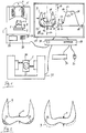
- the Fig. 1 shows a sketch to illustrate the present method for planning a heat treatment of a dental prosthesis part 1 by means of a sintering furnace 2.
- the sintering furnace in this case has insulation elements 3 and 4 heating elements to regulate the temperature within a combustion chamber 5.
- the heat treatment of the dental prosthesis 1 such as sintering, crystallization or glazing is carried out by the chamber 5 is heated by means of the heating elements 4 in a first step. After reaching a certain charging temperature, for example at 300 ° C, the chamber 5 is opened in a second step by a pedestal 6 is moved to a lower end position 7.
- the user like a dentist or dental technician, positions the dental prosthesis 1 to be sintered on the pedestal 6.
- a fourth step the chamber closes again by moving the pedestal back to an upper end position as indicated by the arrows 8 is.
- the chamber 5 is further heated by the heating elements 4 to a holding temperature and this holding temperature is maintained for the duration of a certain holding time.
- a cooling phase then takes place. The cooling phase can be done for example by switching off the heating elements or additionally by opening the chamber 5 by the base is moved to the lower end position 7.
- a 3D model 9 of the tooth replacement part 1 is already present. So that is the construction of the dental prosthesis already completed.
- the 3D model 9 is graphically displayed by means of a display device 39, such as a monitor.
- the 3D model 9 of the dental prosthesis part 1 has certain geometric parameters, such as a lateral wall thickness 10, an occlusal wall thickness 11, a maximum cross-section 12, which is represented by the dashed line, and a total volume 13 of the dental prosthesis part.
- a lateral wall thickness 10 an occlusal wall thickness 11
- a maximum cross-section 12 which is represented by the dashed line
- a total volume 13 of the dental prosthesis part In addition, in the design already determined from which material the dental prosthesis to be produced is to be produced.
- the maximum cross section 12 of the dental prosthesis part can for example be determined perpendicular to a tooth axis 14, which may correspond to an axis of symmetry of the dental prosthesis part.
- the lateral wall thickness 10 can be determined, for example, perpendicular to the tooth axis 14 in the labial area or in the buccal area of the tooth replacement part.
- the occlusal wall thickness 11 can be determined, for example, parallel to the tooth axis 14 on an occlusal surface 15 of the 3D model 9.
- a suitable temperature profile 16 is determined automatically by means of a computer 17.
- the computer 17 may be, for example, a microcomputer, a microchip or a conventional PC.
- the computer 17 may be disposed externally outside the sintering furnace 2.
- the computer 17 may be integrated with the display device 39 in the sintering furnace 2.
- the temperature profile 16 is shown as a graph of a temperature 17 as a function of the time 18.
- a first phase 19 the chamber 5 is heated at a first heating rate to a predrying temperature 20 in a second phase 21, the predrying temperature is maintained for a first hold time, in a third phase 22, the temperature in the chamber 5 is up to a loading temperature, for example, in the amount of 300 ° C heated.
- the chamber 5 is loaded with the tooth replacement part 1 to be sintered, so that the temperature drops slightly.
- the temperature in the chamber 5 rises at a second heating rate up to a second holding temperature 24.
- a sixth phase 25 For example, the heating elements 4 are controlled so that the holding temperature 24 is maintained for a period of a certain holding time.
- the tooth replacement part 1 is cooled.
- the computer is used 17 determines the appropriate temperature profile 16.
- the heating rates for the heating phases 19, 23, the holding temperatures 20, 24 and the holding times of the phases 21, 25 are determined.
- partial regions 27 and 28 which are shown in dashed lines, can be marked, which do not fulfill defined limit values of the geometry parameters.
- partial regions 27, 28 can be marked, which exceed a limit value of 6 mm with respect to the occlusal wall thickness.
- these marked portions 27 and 28 may be deformed either manually by the user using a virtual tool 29, such as a cursor, or automatically by means of the computer 17, so that the limits with respect to the geometry parameters are met.
- the control of the virtual tool 29 can be done by means of connected input means, such as a keyboard 30 and a mouse 31.
- a keyboard 30 and a mouse 31 By adapting or deforming the 3D model 9, an adapted 3D model 32 is generated, which is represented by a dashed line.
- the tooth replacement part 1 to be sintered from a blank 34 is subsequently machined out fully automatically by means of a CAM processing machine 33.
- the sintering takes place by means of the sintering furnace 2, as described above.
- the advantage of this method is therefore that even before the production of the dental prosthesis part by means of the CAM processing machine 33 and before the sintering of the dental prosthesis 1 by means of the sintering furnace 2, a determination of a suitable temperature profile 16 and a plausibility check and a possible adaptation of the 3D model. 9 can be done.
- the determination of the temperature profile 16 can be effected, for example, by a selection from a plurality of temperature profiles, which are stored in a memory 35.
- This memory 35 is integrated in the computer 17.
- the temperature profiles can be stored in a second memory 36, which is integrated into the sintering furnace 2.
- the determination of the appropriate temperature profile can also be done by calculating an individual temperature profile, which is calculated by the computer 17.
- the present method of scheduling a heat treatment may also be for multiple dental prostheses and multiple heat treatments before commencing sintering.
- An order may include the characteristics such as the name of the patient, the type of denture, such as full crown, partial crown or bridge, the material for the production of the dental prosthesis, the type of heat treatment, such as sintering, crystallization or glazing, and the Include type of suitable temperature profile.
- the jobs with these characteristics can be displayed for example by means of a display 37, which is integrated into the sintering furnace 2.
- the orders with the characteristic data could also be displayed by means of the display device 39.
- the user can select the respective order with the associated temperature profile before carrying out the sintering. Subsequently, the sintering is carried out automatically with a suitable temperature profile.
- the Fig. 2 shows the 3D model 9 of the dental prosthesis part 1 Fig. 1 , Wherein the areas 27 and 28 are marked, which exceed a limit, for example, in the amount of 6 mm with respect to the occlusal wall thickness.
- an adapted 3D model 32 is generated. On the basis of the adapted 3D model 32 then the tooth replacement part 1 by means of the CAM processing machine 33 from Fig. 1 worked out.
- the Fig. 3 shows several temperature profiles for performing a sintering, wherein the temperature 17 is plotted in ° C as a function of time 18 in minutes.
- a first temperature profile 40 has a heating rate 41 in the amount of 100 ° C / min, a holding temperature 42 in the height of 1580 ° C and a holding time 43 in the amount of 6 minutes.
- a second temperature profile 44 has a heating rate 45 in the amount of 100 ° C / min, a holding temperature 46 in the height of 1510 ° C and a holding time 47 of 30 minutes.
- a third temperature profile 48 shown by a dotted-dashed line, has a heating rate 49 of 25 ° C, a holding temperature 50 of 1510 ° C, and a hold time 51 of 120 minutes.
- a fourth temperature profile 52 shown by a dashed line, has a predrying phase 53 wherein the temperature is heated to a predrying temperature 54 and held for 20 minutes. Subsequently, the heating phase is carried out at a heating rate 55 in the amount of 100 ° C / minute up to a holding temperature 56 in the amount of 1510 ° C. This holding temperature 56 is then held for the duration of a hold time 57 of 30 minutes, followed by a cooling phase.
- a fifth temperature profile 58 has a heating rate 59 in the amount of 300 ° C / min, a holding temperature 60 in the height of 1580 ° C and a holding time of 6 minutes.
- the first temperature profile 40 is particularly suitable for small dental prostheses with a small wall thickness, for example, below 6 mm and a low total volume, the high heating rate 41 and the low holding time 43 of 6 minutes allows a short sintering time.
- the second temperature profile 44 is suitable for medium-sized dental replacement parts, for example, with a maximum wall thickness of more than 6 mm and consisting of at most six individual teeth.
- the third temperature profile 48 is suitable for large dentures such as bridges of more than six teeth.
- the fourth temperature profile 52 is suitable for materials that require pre-drying prior to sintering.
- the 3D model 9 out Fig. 1 and Fig. 2 can be deformed by the user or automatically by means of the computer in such a way that the requirements or the limit values for a specific temperature profile are met.
- Fig. 2 is shown that the 3D model 9 has been adjusted so that the occlusal wall thickness 11 does not exceed a limit in the height of 6 mm. So that can be for after the adapted 3D model 32 to be produced tooth replacement part 1 sintering with the first temperature profile 40 instead of the second temperature profile 44.
- the advantage of this adaptation is therefore that the duration of the sintering is shortened.
Landscapes
- Health & Medical Sciences (AREA)
- Engineering & Computer Science (AREA)
- Chemical & Material Sciences (AREA)
- Oral & Maxillofacial Surgery (AREA)
- Dentistry (AREA)
- Epidemiology (AREA)
- Life Sciences & Earth Sciences (AREA)
- Animal Behavior & Ethology (AREA)
- General Health & Medical Sciences (AREA)
- Public Health (AREA)
- Veterinary Medicine (AREA)
- Ceramic Engineering (AREA)
- Manufacturing & Machinery (AREA)
- General Engineering & Computer Science (AREA)
- Mechanical Engineering (AREA)
- Clinical Laboratory Science (AREA)
- Materials Engineering (AREA)
- Structural Engineering (AREA)
- Organic Chemistry (AREA)
- Inorganic Chemistry (AREA)
- Composite Materials (AREA)
- Dental Prosthetics (AREA)
Description
- Die Erfindung betrifft ein Verfahren zur Planung einer Sinterung eines Zahnersatzteils, wobei ein 3D-Modell des herzustellenden Zahnersatzteils bereits konstruiert wurde.
- Aus dem Stand der Technik sind mehrere Verfahren zur Planung von Sinterungsprozessen bekannt. Vor der Durchführung der Sinterung mittels eines Sinterofens kann der Benutzer ein bestimmtes Programm mit einem passenden Temperaturprofil für das hergestellte Zahnersatzteil aussuchen, wobei der Benutzer das verwendete Material und die Abmessungen des Zahnersatzteils berücksichtigt.
-
DE 10 2011 056 211 B3 offenbart eine Vorrichtung und ein Verfahren zum Sintern von Sintergut, insbesondere Zahngerüsten, wobei eine Schale von einem Verschlusselement abgedeckt ist, wobei der Rahmen der Schale mit einer Schutzgaszuführung verbunden ist. Die Heizrate, die Haltetemperatur sowie eine Abkühlzeit können manuell eingestellt werden. -
EP 2 620 733 A1 offenbart ein Dentalgerät, wie ein dentaler Brennofen, mit wenigstens einem Betriebsprogramm, mit einem Speicher und mit wenigstens einer Erfassungsvorrichtung, wie einer Kamera. Mittels der Kamera kann das Objekt erfasst werden und mittels einer Anzeigevorrichtung das Objekt in der erfassten Form dargestellt werden. In einer Datenbank sind mehrere vorgegebene Referenzobjekte enthalten, wobei bei Übereinstimmung einer bestimmten Anzahl von Merkmalen eines Referenzobjektes mit dem Bild des erfassten Objekts die Auslösung eines dazugehörigen Betriebsprogramms erfolgt. -
US 2009/0079101 A1 offenbart einen Sinterofen mit einer wärmeisolierten Kamera und einem Temperaturmessgerät. Bei einem Temperaturprofil beträgt die Heizrate 140 °C pro Minute, eine Haltetemperatur von 1400 °C und eine Abkühlrate von 50 °C pro Minute. -
DE 10 2008 013 555 A1 offenbart einen Sinterofen zur Herstellung von Zahneratzteilen, wobei das Sintern der Zahnersatzteile entlang einer Sinterstrecke erfolgt. Die Zahnersatzteile werden beim Durchfahren dieser Sinterstrecke unterschiedlichen Temperaturen ausgesetzt. Die Sinterstrecke ist also in einzelne Sinterstreckensegmente eingeteilt, die auf verschiedene Temperaturen eingeregelt werden können. Die Träger mit den zu sinternden Zahnersatzteilen werden entlang der Sinterstrecke mittels eines Schiebers bewegt. Für jeden der Sinterstreckensegmente können unterschiedliche Temperaturen eingestellt werden. Dadurch können unterschiedliche Temperaturverläufe für die Sinterung unterschiedlicher Keramiken eingestellt werden. - Weitere Sinteröfen und entsprechende Verfahren sind aus der
US 2011/0147968 A1 , derUS 4,796,688 A , derEP 2 620 733 A1 sowie derWO 2014/016320 A1 bekannt. - Ein Nachteil dieser Verfahren ist, dass der Benutzer durch Bedienungsfehler falsche Temperaturprofile einstellen kann, so dass dies zu Fertigungsfehlern des herzustellenden Zahnersatzteils führen kann. Ein Temperaturprofil mit einer zu hohen Heizrate kann beispielsweise bei Oxidkeramiken zu Rissen an der Oberfläche des Zahnersatzteils führen.
- Die Aufgabe der vorliegenden Erfindung besteht daher darin, ein Verfahren zur Planung einer Sinterung bereitzustellen, dass solche Bedienungsfehler verhindert werden.
- Die Erfindung betrifft ein Verfahren zur Planung einer Wärmebehandlung eines Zahnersatzteils, wobei ein 3D-Modell des herzustellenden Zahnersatzteils bereits vorliegt. In Abhängigkeit von bestimmten Geometrieparametern des herzustellenden Zahneratzteils und von bestimmten Materialparametern des herzustellenden Zahnersatzteils wird ein Temperaturprofil für die Wärmebehandlung, wie Sinterung, Kristallisierung oder Glasierung, des Zahnersatzteils automatisch mittels eines Computers bestimmt, wobei die Materialparameter eines zur Herstellung des Zahnersatzteils ausgewählten Materials eine Wärmeleitfähigkeit, eine Thermoschockbeständigkeit, eine maximale Aufheizrate und/oder ein Temperaturgrenzwert für eine Phasenumwandlung des Materials sind.
- Bei einer zunehmenden Wärmeleitfähigkeit des verwendeten Materials kann das Zahnersatzteil schneller durchgesintert werden, so dass die Haltezeit des Temperaturprofils verringert werden kann.
- Bei einer hohen Thermoschockbeständigkeit des Materials kann auch die Heizrate erhöht werden, ohne Beschädigungen des Zahnersatzteils während der Sinterung zu verursachen.
- Nach dem vorliegenden Verfahren kann eine theoretische maximale Heizrate für das jeweilige Zahnarztteil ermitteln bzw. bestimmt werden. Zur Bestimmung dieser maximale Heizrate können mechanische Kennwerte des verwendeten Materials, wie ein linearer Ausdehnungskoeffizient, ein E-Modul, Festigkeit, eine Querkontraktionszahl, eine Risszähigkeit, eine initiale Risslänge oder ein Formfaktor, sowie thermodynamische Kennwerte, wie eine volumenbezogene Wärmekapazität oder eine Wärmeleitfähigkeit, sowie die Geometrieparameter des Zahnersatzteils verwendet werden.
- Bei diesem Verfahren wurde die Konstruktion des Zahnersatzteils bereits durchgeführt, so dass ein 3D-Modell des Zahnersatzteils vorliegt. Das herzustellende Zahnersatzteil kann beispielsweise eine Vollprothese für ein Implantat, eine Dentalprothese, eine Vollkrone, eine Teilkrone, eine Brücke aus mehreren ganzen Zähnen oder ein Inlay sein. Aufgrund von bestimmten Auswahlkriterien wird in Abhängigkeit von Geometrieparametern und/oder der Materialparameter des ausgewählten Materials das passende Temperaturprofil bestimmt. Die Bestimmung des Temperaturprofils kann beispielsweise durch eine automatische Auswahl des Temperaturprofils aus einer Vielzahl unterschiedlicher Temperaturprofile einer Datenbank oder durch Berechnung eines individuellen Temperaturprofils erfolgen. Das Temperaturprofil kann mindestens einen Aufheizschritt oder auch mehrere Aufheizschritte enthalten, wobei maßgeblich ist, dass eine maximale Heizrate, die abhängig vom verwendeten Material und maßgeblich von der Wandstärke des Zahnersatzteils abhängt, nicht überschritten wird. Denn dies könnte zu Rissen an der Oberfläche des Zahnersatzteils oder auch zum Abplatzen der oberen Schichten des Zahnersatzteils führen. Denn während des Sinterungsprozesses kann die äußere Schicht des Zahnersatzteils schneller schrumpfen als die inneren Schichten des Zahnersatzteils, so dass es zu mechanischen Spannungen führt. Nach dem Aufheizen des Zahnersatzteils mit der festgelegten Heizrate wird eine Haltetemperatur für die Dauer einer bestimmten Haltezeit behalten, wobei anschließend eine Abkühlphase erfolgt. Die Abkühlphase kann beispielsweise durch das Öffnen einer Tür des verwendeten Sinterofens erfolgen, so dass kühle Luft hineinströmen kann. Die Haltetemperatur und die Haltezeit werden so gewählt, dass zwar das herzustellende Zahnersatzteil vollständig durchgesintert wird jedoch keine Übersinterung erfolgt. Bei einer Übersinterung kann eine Korngröße des verwendeten zu sinternden Materials einen festgelegten Grenzwert überschreiten, so dass dies zu einer geringeren Festigkeit des Zahnersatzteils führen kann.
- Ein Vorteil dieses Verfahrens besteht darin, dass Bedienungsfehler bei der manuellen Auswahl eines passenden Temperaturprofils ausgeschlossen werden, so dass dadurch Fertigungsfehler verhindert werden können.
- Ein weiterer Vorteil dieses Verfahrens besteht darin, dass unter Berücksichtigung der Geometrieparameter und/oder der Materialparameter ein passendes Temperaturprofil ausgewählt werden kann, das eine möglichst geringe Dauer mit einer möglichst hohen Heizrate und möglichst geringer Haltezeit aufweist, so dass dadurch die Dauer der Wärmebehandlung des Zahnersatzteils verkürzt wird.
- Vorteilhafterweise können die Geometrieparameter des Zahnersatzteils eine maximale laterale Wandstärke, eine maximale okklusale Wandstärke, ein Verhältnis aus der maximalen okklusalen Wandstärke und der maximalen lateralen Wandstärke, ein maximaler Querschnitt des Zahneratzteils, ein Gesamtvolumen des Zahnersatzteils, eine maximale Gesamtlänge des Zahnersatzteils und/oder eine maximale Querschnittsänderung des Zahneratzteils sein.
- Die maximale laterale Wandstärke bezieht sich auf die seitliche Wandstärke des Zahnersatzteils beispielsweise an den Labialflächen bei Schneidezähnen bzw. bei Bukkalflächen von Backenzähnen. Die maximale okklusale Wandstärke bezieht sich auf die Wandstärke einer Okklusalfläche des Zahneratzteils. Der maximale Querschnitt des Zahnersatzteils bezieht sich auf einen Querschnitt senkrecht zu einer Zahnachse des Zahnersatzteils.
- Aufgrund dieser Geometrieparameter wird also ein passendes Temperaturprofil ausgewählt, wobei insbesondere eine bestimmte Heizrate und eine bestimmte Haltezeit bei einer Haltetemperatur bestimmt werden.
- Vorteilhafterweise kann das Temperaturprofil so bestimmt werden, dass bei einer steigenden maximalen lateralen Wandstärke, bei einer steigenden maximalen okklusalen Wandstärke, bei einem steigenden maximalen Bauteilquerschnitt und/oder bei einem steigenden Gesamtvolumen des Zahnersatzteils eine Heizrate des Temperaturprofils sinkt, eine Haltezeit des Temperaturprofils steigt und/oder eine Haltetemperatur des Temperaturprofils sinkt.
- Bei einer steigenden Wandstärke nehmen auch die mechanischen Spannungen während der Sinterung zu, so dass die Heizrate verringert werden muss, um Beschädigungen am Zahnersatzteil zu verhindern.
- Bei einem zunehmenden Bauteilquerschnitt bzw. beim Gesamtvolumen des Zahnersatzteils nimmt die Haltezeit zu, da es länger dauert das Zahnersatzteil vollständig durchzusintern.
- Vorteilhafterweise kann das Temperaturprofil so bestimmt werden, dass bei einer steigenden Wärmeleitfähigkeit und/oder einer steigenden Thermoschockbeständigkeit eine Heizrate des Temperaturprofils steigt.
- Dadurch kann die Heizrate abhängig von der Wärmeleitfähigkeit und von der Thermoschockbeständigkeit des höheren Materials erhöht werden, so dass die Gesamtdauer der Sinterung bekürzt werden kann.
- Vorteilhafterweise kann die Wärmebehandlung eine Sinterung, eine Kristallisierung, eine Kombination aus einer Sinterung und einer Glasierung oder eine Kombination aus einer Kristallisierung und einer Glasierung sein.
- Die Sinterung kann für Oxidkeramiken, wie Zirkoniumdioxid oder Aluminiumoxid, sowie für Nichtedelmetalllegierungen, wie eine CoCrMo-Legierung, angewendet werden.
- Eine Kristallisierung erfolgt insbesondere bei Glaskeramiken mit dem Werkstoffsystem Lithiumdisilikat.
- Fertig gesintert werden dentale Restaurationen, die aus angesinterten Oxidkeramiken insbesondere Zirkoniumdioxid und Aluminiumoxid gefertigt wurden. Aus Pulver gepresste und angesinterte Rohlinge aus Metall, insbesondere aus CoCrMo-Legierungen, müssen nach der mechanischen Weiterbearbeitung durch Schleifen oder Fräsen zu dentalen Restaurationen ebenfalls gesintert werden.
- Alle metallischen oder keramischen Grundwerkstoffe können durch weitere Brennprozesse nach der Sinterung verblendet oder glasiert werden. Zusammen mit der Glasur als ein so genannter Oberflächenfinish kann auch eine Bemalung erfolgen, die im gleichen Ofenprozess gebrannt wird.
- Die Glaskeramik hat darüber hinaus den Vorteil, dass sie im selben Brennprozess kristallisiert, bemalt und glasiert werden kann.
- Vorteilhafterweise kann das ausgewählte Material zur Herstellung des Zahnersatzteils Zirkoniumdioxid sein, wobei das herzustellende Zahnersatzteil ein einzelner Zahn, eine Vollkrone, eine Teilkrone oder ein Inlay ist. Das Gesamtvolumen des Zahnersatzteils entspricht dabei höchstens dem Volumen eines Backenzahns, wobei die maximale laterale Wandstärke und/oder die maximale okklusale Wandstärke unterhalb eines Grenzwertes von 6 mm liegen. Unter Berücksichtigung dieser Faktoren wird ein erstes Temperaturprofil für eine Sinterung mit einer Heizrate zwischen 100 °C/Minute und 400 °C/Minute, mit einer Haltetemperatur zwischen 1500 °C und 1600 °C sowie einer Haltezeit zwischen 5 Minuten und 10 Minuten bestimmt.
- Durch die relativ geringe Wandstärke und das geringe Gesamtvolumen des Zahnersatzteils wird eine relativ hohe Heizrate ermöglicht, so dass die Gesamtdauer verkürzt wird. Das geringe Gesamtvolumen ermöglicht auch, dass das Zahnersatzteil schneller gesintert ist, so dass die Haltezeit relativ gering gewählt ist und die gesamte Dauer der Sinterung damit zusätzlich verkürzt wird. Das erste Temperaturprofil ermöglicht also eine schnelle Sinterung für relativ kleine Zahnersatzteile.
- Vorteilhafterweise kann das ausgewählte Material Zirkoniumdioxid sein, wobei das herzustellende Zahnersatzteil eine Brücke aus höchstens 6 verbundenen Zähnen ist oder aus höchstens 6 einzelnen Zähnen besteht. Unter Berücksichtigung dieser Faktoren wird ein zweites Temperaturprofil für eine Sinterung mit einer Heizrate zwischen 70 °C/Minute und 200 °C/Minute, mit einer Haltetemperatur zwischen 1450 °C und 1550 °C sowie einer Haltezeit zwischen 20 Minuten und 40 Minuten bestimmt.
- Das zweite Temperaturprofil wird für Zahnersatzteile mit einem Gesamtvolumen von höchstens sechs Zähnen gewählt, wobei eine längere Haltezeit zum Durchsintern des Zahnersatzteils als beim ersten Temperaturprofil erforderlich ist.
- Vorteilhafterweise kann das ausgewählte Material Zirkoniumdioxid sein, wobei das herzustellende Zahnersatzteil mehr als 6 einzelne Zähne umfasst, wobei ein drittes Temperaturprofil für eine Sinterung mit einer Heizrate zwischen 10 °C/Minute und 70 °C/Minute, mit einer Haltetemperatur zwischen 1500 °C und 1600 °C und einer Haltezeit zwischen 100 Minuten und 140 Minuten bestimmt wird.
- Das dritte Temperaturprofil wird für relativ große Zahnersatzeile mit einem Gesamtvolumen von mehr als sechs Zähnen gewählt, wobei die Heizrate im Vergleich zum ersten Temperaturprofil und zum zweiten Temperaturprofil deutlich verringert wird, um Risse an der Oberfläche des Zahnersatzteils zu verhindern. Die Haltezeit wird im Vergleich zum ersten Temperaturprofil und zum zweiten Temperaturprofil deutlich erhöht, um eine vollständige Durchsinterung des Zahnersatzteils zu gewährleisten.
- Vorteilhafterweise kann das ausgewählte Material Aluminiumoxid (Al2O3) sein, wobei ein viertes Temperaturprofil für eine Sinterung mit einer Heizrate zwischen 10 °C/Minute bis 70 °C/Minute, mit einer Haltetemperatur zwischen 1500°C und 1600°C sowie einer Haltezeit zwischen 100 Minuten und 140 Minuten bestimmt wird.
- Das vierte Temperaturprofil ist für das Material Aluminiumoxid geeignet, wobei unabhängig von der Größe des Zahnersatzteils die Heizrate und die Haltezeit wie beim dritten Temperaturprofil gewählt ist.
- Vorteilhafterweise kann das 3D-Modell des herzustellenden Zahnersatzteils mittels einer Anzeigevorrichtung graphisch dargestellt werden, wobei bestimmte Teilbereiche des 3D-Modells graphisch markiert werden, die bezüglich der labialen Wandstärke oder bezüglich der okklusalen Wandstärke einen bestimmten Grenzwert überschreiten.
- Die Anzeigevorrichtung kann beispielsweise ein Monitor sein, der das konstruierte 3D-Modell des herzustellenden Zahnersatzteils graphisch darstellt. Diejenigen Bereiche bei denen die Wandstärke den bestimmten Grenzwert, wie beispielsweise in der Höhe von 3 mm, überschreitet, werden graphisch markiert. Auf diese Weise kann der Benutzer erkennen welche Teilbereiche des 3D-Modells die Geometrieparameter für das erste Temperaturprofil bzw. für das zweite Temperaturprofil nicht erfüllen. Der Benutzer, wie ein Zahnarzt oder ein Zahntechniker, kann dann diese markierten Teilbereiche entsprechend anpassen.
- Vorteilhafterweise kann der Benutzer die markierten Teilbereiche manuell unter Verwendung virtueller Werkzeuge so anpassen bzw. dass die markierten Teilbereiche automatisch mittels des Computers so angepasst werden, dass der Grenzwert für die labiale Wandstärke oder die okklusale Wandstärke unterschritten wird. Dadurch kann für das nach diesem angepassten 3D-Modell herzustellende Zahnersatzteil die schnellere Sinterung mit dem ersten Temperaturprofil anstatt mit dem zweiten Temperaturprofil durchgeführt werden kann.
- Der Benutzer kann also die markierten Bereiche so anpassen, dass der Grenzwert für die Wandstärke, beispielsweise in der Höhe von 3 mm, unterschritten wird. Dadurch werden die Geometrieparameter für das erste Temperaturprofil erfüllt, so dass die Sinterung mit dem ersten Temperaturprofil durchgeführt werden kann, so dass dies zu einer Verkürzung der Gesamtdauer der Sinterung im Vergleich zur Sinterung mit dem zweiten Temperaturprofil führt.
- Vorteilhafterweise kann die Bestimmung des passenden Temperaturprofils durch eine Auswahl aus mehreren Temperaturprofilen erfolgen, die in einer Datenbank abgespeichert sind.
- Die unterschiedlichen Temperaturprofile können beispielsweise in einem Speicher abgespeichert werden, der in einem Mikrocomputer angeordnet ist, der in den Sinterofen integriert ist. Dieser Speicher kann alternativ auch in einen Computer integriert sein, der außerhalb des Sinterofens angeordnet ist.
- Die Kenndaten der Temperaturprofile, wie die Heizrate, die Haltezeit und/oder die Haltetemperatur können mittels einer Anzeigevorrichtung graphisch dargestellt werden. Die Anzeigevorrichtung kann beispielsweise ein Display sein, das am Sinterofen angepasst ist. Dabei erfolgt also die Auswahl automatisch mittels eines Computers, wobei die Kenndaten des ausgewählten Temperaturprofils graphisch angezeigt werden können.
- Vorteilhafterweise kann die Bestimmung des passenden Temperaturprofils durch eine Berechnung eines individuellen Temperaturprofils erfolgen, der unter Berücksichtigung der Geometrieparameter und/oder der Materialparameter des herzustellenden Zahnersatzteils individuell berechnet wird.
- Dadurch wird also ein individuelles Temperaturprofil unter Berücksichtigung der Geometrieparameter und/oder der Materialparameter berechnet. Dabei können bekannte mathematische Verfahren, wie Interpolation, verwendet werden.
- Die Erfindung betrifft weiterhin ein System zur Durchführung eines Verfahrens zur Planung einer Wärmebehandlung eines Zahnersatzteils mittels eines Sinterofens umfassend einen Computer, wobei ein 3D-Modell des herzustellenden Zahnersatzteils bereits vorliegt. In Abhängigkeit von bestimmten Geometrieparametern des herzustellenden Zahneratzteils und von bestimmten Materialparametern des herzustellenden Zahnersatzteils ist dabei ein Temperaturprofil für die Sinterung des Zahnersatzteils automatisch mittels des Computers bestimmbar.
- Das System ermöglicht also die Durchführung des oben genannten Verfahrens, wobei mittels des Computers automatisch ein passendes Temperaturprofil für das jeweilige Zahnersatzteil abhängig von den Geometrieparametern und von den Materialparametern bestimmt wird.
- Ein Vorteil dieses Systems besteht darin, dass Bedienungsfehler durch den Benutzer, wie ein Zahnarzt oder ein Zahntechniker, bei der manuellen Auswahl eines passenden Temperaturprofils verhindert werden.
- Vorteilhafterweise kann das System eine Anzeigevorrichtung aufweisen, wobei das 3D-Modell des herzustellenden Zahnersatzteils mittels der Anzeigevorrichtung graphisch darstellbar ist, wobei bestimmte Teilbereiche des 3D-Modells graphisch markierbar sind, die bezüglich der labialen Wandstärke oder der okklusalen Wandstärke einen bestimmten Grenzwert überschreiten.
- Durch das Markieren der Teilbereiche, die bestimmte Geometrieparameter, wie die Wandstärke, beispielsweise für das erste Temperaturprofil nicht erfüllen, wird es dem Benutzer ermöglicht die Abmessungen dieser Teilbereiche und damit die erforderlichen Anpassungen des 3D-Modells besser einzuschätzen.
- Vorteilhafterweise kann das System Bedienungsmittel aufweisen, wobei der Benutzer die markierten Teilbereiche manuell unter Verwendung der Bedienungselemente mittels virtueller Werkzeuge so anpasst bzw. dass die markierten Teilbereiche automatisch mittels des Computers so angepasst werden, dass der Grenzwert in der Höhe von 6 mm für die labiale Wandstärke oder die okklusale Wandstärke unterschritten wird. Dadurch kann für das nach diesem angepassten 3D-Modell herzustellende Zahnersatzteil die schnellere Sinterung mit dem ersten Temperaturprofil anstatt mit dem zweiten Temperaturprofil durchgeführt werden kann.
- Durch diese Anpassung des 3D-Modells kann also die Sinterung mit dem ersten Temperaturprofil anstatt mit dem zweiten Temperaturprofil durchgeführt werden, so dass die Gesamtdauer der Sinterung dadurch verkürzt wird.
- Vorteilhafterweise kann das System einen Speicher aufweisen, wobei die Bestimmung des passenden Temperaturprofils durch eine Auswahl aus mehreren Temperaturprofilen erfolgt, die in einer Datenbank im Speicher abgespeichert sind.
- Vorteilhafterweise kann die Bestimmung des passenden Temperaturprofils durch eine Berechnung eines individuellen Temperaturprofils mittels des Computers erfolgen, wobei das individuelle Temperaturprofil unter Berücksichtigung der Geometrieparameter und/oder der Materialparameter des herzustellenden Zahnersatzteils individuell berechnet wird.
- Die Erfindung wird anhand der Zeichnungen erläutert. Es zeigt, die
- Fig. 1
- eine Skizze zur Verdeutlichung des vorliegenden Verfahrens, die
- Fig. 2
- ein 3D-Modell des Zahnersatzteils mit markierten Bereichen, die
- Fig. 3
- zeigt mehrere Temperaturprofile zur Durchführung einer Sinterung.
- Die
Fig. 1 zeigt eine Skizze zur Verdeutlichung des vorliegenden Verfahrens zur Planung einer Wärmebehandlung eines Zahnersatzteils 1 mittels eines Sinterofens 2. Der Sinterofen weist dabei Isolationselemente 3 und Heizelemente 4 auf, um die Temperatur innerhalb einer Brennkammer 5 zu regulieren. Die Wärmebehandlung des Zahnersatzteils 1 wie eine Sinterung, eine Kristallisierung oder eine Glasierung wird durchgeführt, indem in einem ersten Schritt die Kammer 5 mittels der Heizelemente 4 aufgeheizt wird. Nach dem Erreichen einer bestimmten Ladetemperatur, beispielsweise bei 300°C, wird die Kammer 5 in einem zweiten Schritt geöffnet, indem ein Sockel 6 in eine untere Endposition 7 verstellt wird. In einem dritten Schritt positioniert der Benutzer, wie ein Zahnarzt oder Zahntechniker, das zu sinternde Zahnersatzteil 1 auf dem Sockel 6. In einem vierten Schritt schließt die Kammer wieder, Indem der Sockel wieder in eine obere Endposition verstellt wird, wie durch die Pfeile 8 dargestellt ist. In einem fünften Schritt wird mittels der Heizelemente 4 die Kammer 5 weiter auf eine Haltetemperatur aufgeheizt und diese Haltetemperatur wird für die Dauer einer bestimmten Haltezeit gehalten. In einem sechsten Schritt erfolgt dann eine Abkühlphase. Die Abkühlphase kann beispielsweise durch das Abschalten der Heizelemente oder zusätzlich durch das Öffnen der Kammer 5 erfolgen, indem der Sockel in die untere Endposition 7 verstellt wird. - Bei der Durchführung des vorliegenden Verfahrens zur Planung der Wärmebehandlung liegt ein 3D-Modell 9 des Zahnersatzteils 1 bereits vor. Damit ist also die Konstruktion des Zahnersatzteils bereits abgeschlossen. Das 3D-Modell 9 wird mittels einer Anzeigevorrichtung 39, wie eines Monitors graphisch dargestellt. Das 3D-Modell 9 des Zahnersatzteils 1 weist bestimmte Geometrieparameter, wie eine laterale Wandstärke 10, eine okklusale Wandstärke 11, einen maximalen Querschnitt 12, der durch die eine gestrichelte Linie dargestellt ist, sowie ein Gesamtvolumen 13 des Zahnersatzteils, auf. Darüber hinaus wird bei der Konstruktion bereits festgelegt aus welchem Material das herzustellende Zahnersatzteil hergestellt werden soll. Als Material können beispielsweise Oxidkeramiken, wie Zirkondioxid, Aluminiumoxid, oder Nichtedelmetall-Legierungen, wie eine CoCrMo-Legierung, verwendet werden. Der maximale Querschnitt 12 des Zahnersatzteils kann beispielsweise senkrecht zu einer Zahnachse 14 bestimmt werden, die eine Symmetrieachse des Zahnersatzteils entsprechen kann. Die laterale Wandstärke 10 kann beispielsweise senkrecht zur Zahnachse 14 im labialen Bereich bzw. im bukkalen Bereich des Zahnersatzteils ermittelt werden. Die okklusale Wandstärke 11 kann beispielsweise parallel zur Zahnachse 14 auf einer Okklusalfläche 15 des 3D-Modells 9 ermittelt werden. Unter Verwendung der Geometrieparameter 10, 11, 12, 13 und der Materialparameter des ausgewählten Materials wird ein passendes Temperaturprofil 16 automatisch mittels eines Computers 17 ermittelt.
- Der Computer 17 kann beispielsweise ein Mikrocomputer, ein Mikrochip oder ein herkömmlicher PC sein. Der Computer 17 kann extern außerhalb des Sinterofens 2 angeordnet sein. Alternativ kann der Computer 17 mit der Anzeigevorrichtung 39 auch in den Sinterofen 2 integriert sein.
- Das Temperaturprofil 16 ist als ein Graph einer Temperatur 17 in Abhängigkeit von der Zeit 18 dargestellt. In einer ersten Phase 19 wird die Kammer 5 mit einer ersten Heizrate auf eine Vortrocknen-Temperatur 20 aufgeheizt in einer zweiten Phase 21 wird die Vortrocknen-Temperatur für eine erste Haltezeit gehalten, in einer dritten Phase 22 wird die Temperatur in der Kammer 5 bis zu einer Beladen-Temperatur beispielsweise in der Höhe von 300°C aufgeheizt. In einer vierten Phase wird die Kammer 5 mit dem zu sinternden Zahnersatzteil 1 beladen, so dass die Temperatur leicht abfällt. In einer fünften Phase 23 steigt die Temperatur in der Kammer 5 mit einer zweiten Heizrate bis zu einer zweiten Haltetemperatur 24. In einer sechsten Phase 25 werden die Heizelemente 4 so gesteuert, dass die Haltetemperatur 24 für eine Dauer einer bestimmten Haltezeit gehalten wird. In der siebten Phase 26 erfolgt eine Abkühlung des Zahnersatzteils 1. In Abhängigkeit der Geometrieparameter, insbesondere von der maximalen lateralen Wandstärke 10, von der maximalen okklusalen Wandstärke 11 und vom Gesamtvolumen 13, sowie in Abhängigkeit von den Materialparametern des ausgewählten Materials wird also mittels des Computers 17 das passende Temperaturprofil 16 bestimmt. Dabei werden insbesondere die Heizraten für die Aufheizphasen 19, 23, die Haltetemperaturen 20, 24 und die Haltezeiten der Phasen 21, 25 festgelegt.
- Anschließend kann bei einer sogenannten Plausibilitätsprüfung geprüft werden, ob das konstruierte 3D-Modell 9 des Zahnersatzteils 1 bestimmte Anforderungen bezüglich der Geometrieparameter, wie der lateralen Wandstärke oder der okklusalen Wandstärke, erfüllt. Dabei können Teilbereiche 27 und 28, die gestrichelt dargestellt sind, markiert werden, die festgelegte Grenzwerte der Geometrieparameter nicht erfüllen. Beispielsweise können Teilbereiche 27, 28 markiert werden, die bezüglich der okklusalen Wandstärke einen Grenzwert von 6 mm überschreiten. Anschließend können diese markierten Teilbereiche 27 und 28 entweder manuell durch den Benutzer unter Verwendung eines virtuellen Werkzeugs 29, wie eines Cursors, oder automatisch mittels des Computers 17 so verformt werden, dass die Grenzwerte bezüglich der Geometrieparameter erfüllt sind. Die Steuerung des virtuellen Werkzeugs 29 kann mittels angeschlossener Eingabe Mittel, wie einer Tastatur 30 und einer Maus 31, erfolgen. Durch die Anpassung bzw. die Verformung des 3D-Modells 9 wird ein angepasstes 3D-Modell 32 erzeugt, das durch eine gestrichelte Linie dargestellt ist. Anhand des angepassten 3D-Modells 32 wird anschließend mittels einer CAM-Bearbeitungsmaschine 33 das zu sinternde Zahnersatzteil 1 aus einem Rohling 34 vollautomatisch herausgearbeitet. Nach der Herstellung des zu sinternden Zahnersatzteils 1 erfolgt die Sinterung mittels des Sinterofens 2, wie oben beschrieben.
- Der Vorteil dieses Verfahrens besteht also darin, dass bereits vor der Herstellung des Zahnersatzteils mittels der CAM- Bearbeitungsmaschine 33 und vor der Sinterung des Zahnersatzteils 1 mittels des Sinterofens 2 eine Bestimmung eines passenden Temperaturprofils 16 sowie eine Plausibilitätsprüfung und eine mögliche Anpassung des 3D-Modells 9 erfolgen kann.
- Die Bestimmung des Temperaturprofils 16 kann dabei beispielsweise durch eine Auswahl aus mehreren Temperaturprofilen erfolgen, die in einem Speicher 35 abgespeichert sind. Dieser Speicher 35 ist in den Computer 17 integriert. Alternativ dazu können die Temperaturprofile in einem zweiten Speicher 36 abgespeichert sein, der in den Sinterofen 2 integriert ist.
- Die Bestimmung des passenden Temperaturprofils kann auch durch eine Berechnung eines individuellen Temperaturprofils erfolgen, der mittels des Computers 17 berechnet wird.
- Das vorliegende Verfahren zur Planung einer Wärmebehandlung kann auch für mehrere Zahnersatzteile und mehrere Wärmebehandlungen erfolgen, bevor mit der Sinterung begonnen wird. Dabei kann eine Auftragsübersicht erstellt werden, die mehrere Aufträge umfasst. Ein Auftrag kann dabei die Kenndaten, wie den Namen des Patienten, die Art des Zahnersatzes, wie Vollkrone, Teilkrone oder Brücke, das Material zur Herstellung des Zahnersatzteils, die Art der Wärmebehandlung, wie Sinterung, Kristallisierung oder Glasierung, und die Art des passenden Temperaturprofils umfassen. Die Aufträge mit diesen Kenndaten können beispielsweise mittels eines Displays 37 angezeigt werden, das in den Sinterofen 2 integriert ist. Alternativ könnten die Aufträge mit den Kenndaten auch mittels der Anzeigevorrichtung 39 angezeigt werden. Mittels eines Bedienfeldes 38 kann der Benutzer vor der Durchführung der Sinterung den jeweiligen Auftrag mit dem zugeordneten Temperaturverlauf auswählen. Anschließend wird also die Sinterung automatisch mit einem passenden Temperaturprofil durchgeführt.
- Die
Fig. 2 zeigt das 3D-Modell 9 des Zahnersatzteils 1 ausFig. 1 , wobei die Bereiche 27 und 28 markiert sind, die bezüglich der okklusalen Wandstärke ein Grenzwert beispielsweise in Höhe von 6 mm überschreiten. - Nach der Anpassung bzw. der Verformung des 3D-Modells 9, das gestrichelt dargestellt ist, wird ein angepasstes 3D-Modell 32 erzeugt. Anhand des angepassten 3D-Modells 32 wird dann das Zahnersatzteil 1 mittels der CAM-Bearbeitungsmaschine 33 aus
Fig. 1 herausgearbeitet. - Die
Fig. 3 zeigt mehrere Temperaturprofile zur Durchführung einer Sinterung, wobei die Temperatur 17 in °C in Abhängigkeit von der Zeit 18 in Minuten aufgetragen ist. Ein erstes Temperaturprofil 40 weist eine Heizrate 41 in der Höhe von 100 °C/min, eine Haltetemperatur 42 in der Höhe von 1580 °C und eine Haltezeit 43 in der Höhe von 6 Minuten auf. Ein zweites Temperaturprofil 44 weist eine Heizrate 45 in der Höhe von 100 °C/min, eine Haltetemperatur 46 in der Höhe von 1510 °C und eine Haltezeit 47 von 30 Minuten auf. Ein drittes Temperaturprofil 48, das durch eine Strichpunktlinie dargestellt ist, weist eine Heizrate 49 in der Höhe von 25 °C, eine Haltetemperatur 50 in der Höhe von 1510 °C und eine Haltezeit 51 von 120 Minuten auf. Ein viertes Temperaturprofil 52, das durch eine gestrichelte Linie dargestellt ist, weist eine Vortrocknen-Phase 53 auf, wobei die Temperatur auf eine Vortrocknen-Temperatur 54 aufgeheizt wird und 20 Minuten lang gehalten wird. Anschließend erfolgt die Aufheizphase mit einer Heizrate 55 in der Höhe von 100 °C/Minute bis zu einer Haltetemperatur 56 in der Höhe von 1510 °C. Diese Haltetemperatur 56 wird dann für die Dauer einer Haltezeit 57 von 30 Minuten gehalten wobei daraufhin eine Abkühlphase erfolgt. Ein fünftes Temperaturprofil 58 weist eine Heizrate 59 in der Höhe von 300 °C/min, eine Haltetemperatur 60 in der Höhe von 1580 °C und eine Haltezeit von 6 Minuten auf. - Das erste Temperaturprofil 40 ist insbesondere für kleine Zahnersatzteile mit einer geringen Wandstärke beispielsweise unterhalb von 6 mm und einem geringen Gesamtvolumen geeignet, wobei die hohe Heizrate 41 und die geringe Haltezeit 43 von 6 Minuten eine kurze Sinterungsdauer ermöglicht. Das zweite Temperaturprofil 44 ist für mittelgroße Zahnersatzteile beispielsweise mit einer maximalen Wandstärke von mehr als 6 mm und bestehend aus höchstens sechs einzelnen Zähnen geeignet. Das dritte Temperaturprofil 48 ist für große Zahnersatzteile, wie Brücken aus mehr als sechs Zähnen geeignet. Das vierte Temperaturprofil 52 ist für Materialien geeignet, bei denen eine Vortrocknung vor der Sinterung erforderlich ist.
- Das 3D-Modell 9 aus
Fig. 1 und Fig. 2 kann also durch den Benutzer oder automatisch mittels des Computers so verformt werden, dass die Anforderungen bzw. die Grenzwerte für ein bestimmtes Temperaturprofil erfüllt sind. InFig. 2 ist dargestellt, dass das 3D-Modell 9 so angepasst wurde, dass die okklusale Wandstärke 11 einen Grenzwert in der Höhe von 6 mm nicht überschreitet. Damit kann also für das nach dem angepassten 3D-Modell 32 herzustellende Zahnersatzteil 1 die Sinterung mit dem ersten Temperaturprofil 40 anstatt mit dem zweiten Temperaturprofil 44 durchgeführt werden. Der Vorteil dieser Anpassung liegt also darin, dass die Dauer der Sinterung verkürzt wird. -
- 1
- Zahnersatzteil
- 2
- Sinterofen
- 3
- Isolationselement
- 4
- Heizelement
- 5
- Brennkammer
- 6
- Sockel
- 7
- Endposition
- 8
- Pfeil
- 9
- 3D-Modell
- 10
- laterale Wandstärke
- 11
- okklusale Wandstärke
- 12
- Querschnitt
- 13
- Gesamtvolumen
- 14
- Zahnachse
- 15
- Qkklusalfläche
- 16
- Temperaturprofil
- 17
- Computer
- 18
- Zeit
- 19
- erste Phase
- 20
- Vortrocknen-Temperatur
- 21
- zweite Phase
- 22
- dritte Phase
- 23
- fünfte Phase
- 24
- Haltetemperatur
- 25
- sechste Phase
- 26
- siebte Phase
- 27
- Teilbereich
- 28
- Teilbreich
- 29
- virtuelles Werkzeug
- 30
- Tastatur
- 31
- Maus
- 32
- angepasstes 3D-Modell
- 33
- CAM-Bearbeitungsmaschine
- 34
- Rohling
- 35
- Speicher
- 36
- zweiter Speicher
- 37
- Display
- 38
- Bedienfeld
- 39
- Anzeigevorrichtung
- 40
- erstes Temperaturprofil
- 41
- Heizrate
- 42
- Haltetemperatur
- 43
- Haltezeit
- 44
- zweites Temperaturprofil
- 45
- Heizrate
- 46
- Haltetemperatur
- 47
- Haltezeit
- 48
- drittes Temperaturprofil
- 49
- Heizrate
- 50
- Haltetemperatur
- 51
- Haltezeit
- 52
- viertes Temperaturprofil
- 53
- Vortrocknen-Phase
- 54
- Vortrocknen Temperatur
- 55
- Heizrate
- 56
- Haltetemperatur
- 57
- Haltezeit
- 58
- fünftes Temperaturprofil
- 59
- Heizrate
- 60
- Haltetemperatur
Claims (15)
- Verfahren zur Planung einer Wärmebehandlung eines Zahnersatzteils (1), wobei ein 3D-Modell (9) des herzustellenden Zahnersatzteils (1) bereits vorliegt, dadurch gekennzeichnet, dass in Abhängigkeit von bestimmten Geometrieparametern (10, 11, 12, 13) des 3D-Modells (9) und von bestimmten Materialparametern des herzustellenden Zahnersatzteils (1) ein Temperaturprofil (16) für die Wärmebehandlung des Zahnersatzteils (1) automatisch mittels eines Computers (17) bestimmt wird, wobei die Materialparameter eines zur Herstellung des Zahnersatzteils (1) ausgewählten Materials eine Wärmeleitfähigkeit, eine Thermoschockbeständigkeit, eine maximale Aufheizrate und/oder ein Temperaturgrenzwert für eine Phasenumwandlung des Materials sind.
- Verfahren nach Anspruch 1, dadurch gekennzeichnet, dass die Geometrieparameter (10, 11, 12, 13) des 3D-Modells (9) vom Zahnersatzteil (1) eine maximale laterale Wandstärke (10), eine maximale okklusale Wandstärke (11), ein Verhältnis aus der maximalen okklusalen Wandstärke (11) und der maximalen lateralen Wandstärke (10), ein maximaler Querschnitt (12) des Zahnersatzteils (1), ein Gesamtvolumen (13) des Zahnersatzteils (1), eine maximale Gesamtlänge des Zahnersatzteils (1) und/oder eine maximale Querschnittsänderung des Zahnersatzteils (1) sind.
- Verfahren nach Anspruch 2, dadurch gekennzeichnet, dass das Temperaturprofil (16) so bestimmt wird, dass bei einer steigenden maximalen lateralen Wandstärke (10), bei einer steigenden maximalen okklusalen Wandstärke (11), bei einem steigenden maximalen Bauteilquerschnitt und/oder bei einem steigenden Gesamtvolumen (13) des Zahnersatzteils (1) eine Heizrate (41, 45, 49, 55, 59) des Temperaturprofils (16) sinkt, eine Haltezeit (43, 47, 51, 57) des Temperaturprofils (16) steigt und/oder eine Haltetemperatur (42, 46, 50, 56, 60) des Temperaturprofils (16) sinkt.
- Verfahren nach dem Anspruch 1, dadurch gekennzeichnet, dass das Temperaturprofil (16) so bestimmt wird, dass bei einer steigenden Wärmeleitfähigkeit und/oder einer steigenden Thermoschockbeständigkeit eine Heizrate (41, 45, 49, 55, 59) des Temperaturprofils (16) steigt.
- Verfahren nach einem der Ansprüche 1 bis 4, dadurch kennzeichnet, dass die Wärmebehandlung eine Sinterung, eine Kristallisierung, eine Kombination aus einer Sinterung und einer Glasierung oder eine Kombination aus einer Kristallisierung und einer Glasierung ist.
- Verfahren nach einem der Ansprüche 1 bis 5, dadurch gekennzeichnet, dass das ausgewählte Material zur Herstellung des Zahnersatzteils (1) Zirkoniumdioxid (ZrO2) ist, wobei das herzustellende Zahnersatzteil (1) ein einzelner Zahn, eine Vollkrone, mindestens eine Teilkrone oder mindestens ein Inlay ist, wobei das Gesamtvolumen (13) des Zahnersatzteils (1) höchstens dem Volumen eines Backenzahns entspricht, wobei die maximale lateralen Wandstärke (10) und/oder die maximale okklusale Wandstärke (11) unterhalb eines Grenzwertes von 6 mm liegt, wobei ein erstes Temperaturprofil (40) für eine Sinterung mit einer Heizrate (41) zwischen 100 °C/Minute und 400 °C/Minute, mit einer Haltetemperatur (42) zwischen 1500 °C und 1600 °C sowie einer Haltezeit (43) zwischen 5 Minuten und 10 Minuten bestimmt wird.
- Verfahren nach einem der Ansprüche 1 bis 5, dadurch gekennzeichnet, dass das ausgewählte Material Zirkoniumdioxid (ZrO2) ist, wobei das herzustellende Zahnersatzteil eine Brücke aus höchstens 6 verbundenen Zähnen ist oder aus höchstens 6 einzelnen Zähnen bzw. Teilkronen besteht, wobei ein zweites Temperaturprofil (44) für eine Sinterung mit einer Heizrate (45) zwischen 70 °C/Minute und 200 °C/Minute, mit einer Haltetemperatur (46) zwischen 1450 °C und 1550 °C sowie einer Haltezeit (47) zwischen 20 Minuten und 40 Minuten bestimmt wird.
- Verfahren nach einem der Ansprüche 1 bis 5, dadurch gekennzeichnet, dass das ausgewählte Material Zirkoniumdioxid (ZrO2) ist, wobei das herzustellende Zahnersatzteil mehr als 6 einzelne Zähne umfasst, wobei ein drittes Temperaturprofil (48) für eine Sinterung mit einer Heizrate (49) zwischen 10 °C/Minute und 70 °C/Minute, mit einer Haltetemperatur (50) zwischen 1500 °C und 1600 °C und einer Haltezeit (51) zwischen 100 Minuten und 140 Minuten bestimmt wird.
- Verfahren nach einem der Ansprüche 1 bis 5, dadurch gekennzeichnet, dass das ausgewählte Material Aluminiumoxid (Al2O3) ist, wobei ein viertes Temperaturprofil (52) für eine Sinterung mit einer Heizrate (55) zwischen 10 °C/Minute bis 70 °C/Minute, mit einer Haltetemperatur (56) zwischen 1500°C und 1600°C sowie einer Haltezeit (57) zwischen 100 Minuten und 140 Minuten bestimmt wird.
- Verfahren nach einem der Ansprüche 1 bis 9, dadurch gekennzeichnet, dass das 3D-Modell (9) des herzustellenden Zahnersatzteils (1) mittels einer Anzeigevorrichtung (39) graphisch dargestellt wird, wobei bestimmte Teilbereiche (27, 28) des 3D-Modells (9) graphisch markiert werden, die bezüglich der labialen Wandstärke oder der okklusalen Wandstärke (11) einen bestimmten Grenzwert überschreiten.
- Verfahren nach Anspruch 10, dadurch gekennzeichnet, dass der Benutzer die markierten Teilbereiche (27, 28) manuell unter Verwendung virtueller Werkzeuge (29) so anpasst bzw. dass die markierten Teilbereiche (27, 28) automatisch mittels des Computers (17) so angepasst werden, dass der Grenzwert für die labiale Wandstärke (10, 11) oder die okklusale Wandstärke (11) unterschritten wird, so dass für das nach diesem angepassten 3D-Modell (32) herzustellende Zahnersatzteil (1) die Sinterung mit dem ersten Temperaturprofil (40) anstatt mit dem zweiten Temperaturprofil (44) durchgeführt werden kann.
- System zur Durchführung eines Verfahrens zur Planung einer Wärmebehandlung eines Zahnersatzteils (1) mittels eines Sinterofens (2) umfassend einen Computer (17), wobei ein 3D-Modell (9) des herzustellenden Zahnersatzteils (1) bereits vorliegt, dadurch gekennzeichnet, dass in Abhängigkeit von bestimmten Geometrieparametern (10, 11, 12, 13) des 3D-Modells (9) und von bestimmten Materialparametern des herzustellenden Zahnersatzteils (1) ein Temperaturprofil (16) für die Sinterung des Zahnersatzteils (1) automatisch mittels des Computers (17) bestimmbar ist, wobei die Materialparameter eines zur Herstellung des Zahnersatzteils (1) ausgewählten Materials eine Wärmeleitfähigkeit, eine Thermoschockbeständigkeit, eine maximale Aufheizrate und/oder ein Temperaturgrenzwert für eine Phasenumwandlung des Materials sind.
- System nach Anspruch 12, dadurch gekennzeichnet, dass die Geometrieparameter (10, 11, 12, 13) des 3D-Modells (9) vom Zahnersatzteil (1) eine maximale laterale Wandstärke (10), eine maximale okklusale Wandstärke (11), ein Verhältnis aus der maximalen okklusalen Wandstärke (11) und der maximalen lateralen Wandstärke (10), ein maximaler Querschnitt (12) des Zahneratzteils, ein Gesamtvolumen (13) des Zahnersatzteils (1), eine maximale Gesamtlänge des Zahnersatzteils (1) und/oder eine maximale Querschnittsänderung des Zahneratzteils sind.
- System nach Anspruch 12 oder 13, dadurch gekennzeichnet, dass das System eine Anzeigevorrichtung (39) aufweist, wobei das 3D-Modell (9) des herzustellenden Zahnersatzteils (1) mittels der Anzeigevorrichtung (39) graphisch darstellbar ist, wobei bestimmte Teilbereiche (27, 28) des 3D-Modells (9) graphisch markierbar sind, die bezüglich der labialen Wandstärke oder der okklusalen Wandstärke einen bestimmten Grenzwert überschreiten.
- System nach Anspruch 14, dadurch gekennzeichnet, dass das System Bedienungsmittel (30, 31) aufweist, wobei der Benutzer die markierten Teilbereiche (27, 28) manuell unter Verwendung der Bedienungselemente (30, 31) mittels virtueller Werkzeuge (29) so anpasst bzw. dass die markierten Teilbereiche (27, 28) automatisch mittels des Computers (17) so angepasst werden, dass der Grenzwert für die labiale Wandstärke oder die okklusale Wandstärke (11) unterschritten wird, so dass für das nach diesem angepassten 3D-Modell (9, 32) herzustellende Zahnersatzteil die Sinterung mit dem ersten Temperaturprofil (16) anstatt mit dem zweiten Temperaturprofil (16) durchgeführt werden kann.
Applications Claiming Priority (2)
| Application Number | Priority Date | Filing Date | Title |
|---|---|---|---|
| DE102013226497.6A DE102013226497A1 (de) | 2013-12-18 | 2013-12-18 | Verfahren zur Planung einer Sinterung eines Zahnersatzteils |
| PCT/EP2014/078387 WO2015091744A1 (de) | 2013-12-18 | 2014-12-18 | Verfahren zur planung einer sinterung eines zahnersatzteils |
Publications (2)
| Publication Number | Publication Date |
|---|---|
| EP3082643A1 EP3082643A1 (de) | 2016-10-26 |
| EP3082643B1 true EP3082643B1 (de) | 2019-05-22 |
Family
ID=52396643
Family Applications (1)
| Application Number | Title | Priority Date | Filing Date |
|---|---|---|---|
| EP14830521.2A Active EP3082643B1 (de) | 2013-12-18 | 2014-12-18 | Verfahren zur planung einer sinterung eines zahnersatzteils |
Country Status (11)
| Country | Link |
|---|---|
| US (1) | US10939980B2 (de) |
| EP (1) | EP3082643B1 (de) |
| JP (1) | JP6846198B2 (de) |
| KR (1) | KR102027418B1 (de) |
| CN (1) | CN105813593B (de) |
| AU (1) | AU2014368622B2 (de) |
| BR (1) | BR112016012960B1 (de) |
| CA (1) | CA2934416C (de) |
| DE (1) | DE102013226497A1 (de) |
| DK (1) | DK3082643T3 (de) |
| WO (1) | WO2015091744A1 (de) |
Families Citing this family (16)
| Publication number | Priority date | Publication date | Assignee | Title |
|---|---|---|---|---|
| EP2792985B1 (de) * | 2013-04-18 | 2014-11-26 | Amann Girrbach AG | Sintervorrichtung |
| DE102013226497A1 (de) | 2013-12-18 | 2015-06-18 | Sirona Dental Systems Gmbh | Verfahren zur Planung einer Sinterung eines Zahnersatzteils |
| DE102016202703A1 (de) | 2016-02-22 | 2017-08-24 | Sirona Dental Systems Gmbh | Ofen für Dentalbauteile und wärmefeste Unterlage |
| DE102016202902A1 (de) | 2016-02-24 | 2017-08-24 | Sirona Dental Systems Gmbh | Induktionsofen und Verfahren zur Durchführung einer Wärmebehandlung eines Zahnersatzteils |
| DE102016214725B4 (de) | 2016-08-09 | 2018-07-26 | Sirona Dental Systems Gmbh | Rohling und Verfahren zur Herstellung eines Zahnersatzteils |
| KR101785608B1 (ko) | 2016-08-18 | 2017-10-17 | 이수영 | 치과용 소결장치의 온도 제어 장치 및 방법 |
| CN108007203B (zh) * | 2016-10-31 | 2019-11-22 | 辽宁爱尔创生物材料有限公司 | 一种快速烧结系统及快速烧结方法 |
| EP3759061A1 (de) | 2018-02-28 | 2021-01-06 | 3M Innovative Properties Company | Verfahren zur herstellung eines dentalen zirkonoxidartikels mit einem schnellsinterprozess |
| DE102018119080A1 (de) * | 2018-08-06 | 2020-02-06 | Redios-Tec Gmbh | Verfahren zur Herstellung eines Dentalbauteils |
| EP3659548B1 (de) | 2018-11-29 | 2025-01-01 | Ivoclar Vivadent AG | Verfahren zur herstellung einer dentalen restauration |
| US20220211587A1 (en) | 2019-04-25 | 2022-07-07 | Kuraray Noritake Dental Inc. | Zirconia pre-sintered body suitable for dental use and method for producing the same |
| DE102020121993A1 (de) | 2020-08-21 | 2022-02-24 | Ivoclar Vivadent Ag | Aluminiumoxid-Keramikmaterial |
| KR102441113B1 (ko) * | 2020-09-28 | 2022-09-06 | 가톨릭대학교 산학협력단 | 치과 수복재의 설계방법 |
| KR102490874B1 (ko) | 2021-01-04 | 2023-01-19 | 왕병철 | 치과 보철용 지르코니아 소결로 |
| EP4137312A1 (de) | 2021-08-16 | 2023-02-22 | Ivoclar Vivadent AG | Verfahren zur herstellung einer dentalen restauration |
| DE102024002136B3 (de) * | 2024-07-02 | 2025-09-04 | Thomas Baholzer | Dental Hybridofen |
Family Cites Families (22)
| Publication number | Priority date | Publication date | Assignee | Title |
|---|---|---|---|---|
| EP0191350A3 (de) | 1985-02-15 | 1987-11-19 | BEGO Bremer Goldschlägerei Wilh. Herbst GmbH & Co. | Verfahren zur Steuerung des Schmelz- und Giessvorganges der Feingiesstechnik, insbesondere der Dentaltechnik, und Vorrichtung zur Durchführung des Verfahrens |
| US5239178A (en) | 1990-11-10 | 1993-08-24 | Carl Zeiss | Optical device with an illuminating grid and detector grid arranged confocally to an object |
| ATE137588T1 (de) | 1990-11-10 | 1996-05-15 | Grosskopf Rudolf Dr Ing | Optische abtastvorrichtung mit konfokalem strahlengang, in der lichtquellen- und detektormatrix verwendet werden |
| DE19651667C2 (de) | 1996-12-12 | 2003-07-03 | Rudolf Groskopf | Vorrichtung zur dreidimensionalen Untersuchung eines Objektes |
| DE19824497A1 (de) * | 1998-06-02 | 1999-12-09 | Dekema Dental Keramikoefen Gmb | Brennofen für Zahnersatz oder-teilersatz |
| IL125659A (en) | 1998-08-05 | 2002-09-12 | Cadent Ltd | Method and device for three-dimensional simulation of a structure |
| JP3440465B2 (ja) | 1998-12-17 | 2003-08-25 | 株式会社高岳製作所 | マルチスリット走査撮像装置 |
| EP1371939A1 (de) | 2002-05-15 | 2003-12-17 | Icos Vision Systems N.V. | Vorrichtung zur Messung in drei Dimensionen der topographischen Oberflächenform eines Gegenstandes |
| JP2004347208A (ja) * | 2003-05-21 | 2004-12-09 | Koito Ind Ltd | 陶芸用電気炉 |
| NO322775B1 (no) | 2004-09-24 | 2006-12-11 | Tomra Systems Asa | Anordning og fremgangsmate for detektering av et medium |
| DE102006032655A1 (de) * | 2006-07-13 | 2008-01-17 | Zubler Gerätebau GmbH | Dentaltechnikofen und Verfahren zur Positionssteuerung einer Verschlussplatte an einem Dentaltechnikofen |
| DE102006036132B4 (de) * | 2006-08-01 | 2019-04-25 | Zubler Gerätebau GmbH | Verfahren zum Aufheizen einer für Dentalkeramik verwendeten, vorgewärmten Pressmuffel in einem Pressofen |
| US20090079101A1 (en) * | 2007-04-27 | 2009-03-26 | Jurgen Laubersheimer | Densification Process of Ceramics And Apparatus Therefor |
| DE102008012578C5 (de) * | 2008-03-05 | 2022-04-07 | Ivoclar Vivadent Ag | Dentalofen |
| DE102008013555A1 (de) | 2008-03-11 | 2009-10-15 | Straumann Holding Ag | Sinterofen für Dentalpräparate und Verfahren zum Sintern von Dentalpräparaten |
| WO2011118839A1 (ja) | 2010-03-24 | 2011-09-29 | 株式会社アドバンス | 歯科用補綴物計測加工システム |
| DE102011056211B3 (de) * | 2011-12-09 | 2013-02-07 | Degudent Gmbh | Verfahren und Vorrichtung zum Sintern von Sintergut |
| EP2620733B1 (de) | 2012-01-27 | 2014-03-19 | Ivoclar Vivadent AG | Dentalgerät |
| JP2013153929A (ja) | 2012-01-30 | 2013-08-15 | Daikoku Denki Co Ltd | 遊技場用管理システム |
| DE102012213279A1 (de) * | 2012-07-27 | 2014-01-30 | Sirona Dental Systems Gmbh | Sinterofen für Bauteile aus einem Sinterwerkstoff, insbesondere für Dentalbauteile und Verfahren zur Sinterung derartiger Bauteile |
| WO2014039268A1 (en) * | 2012-09-04 | 2014-03-13 | 3M Innovative Properties Company | Method of producing a dental restoration |
| DE102013226497A1 (de) | 2013-12-18 | 2015-06-18 | Sirona Dental Systems Gmbh | Verfahren zur Planung einer Sinterung eines Zahnersatzteils |
-
2013
- 2013-12-18 DE DE102013226497.6A patent/DE102013226497A1/de not_active Withdrawn
-
2014
- 2014-12-18 JP JP2016532541A patent/JP6846198B2/ja active Active
- 2014-12-18 DK DK14830521.2T patent/DK3082643T3/da active
- 2014-12-18 US US15/105,530 patent/US10939980B2/en active Active
- 2014-12-18 CA CA2934416A patent/CA2934416C/en active Active
- 2014-12-18 CN CN201480069312.6A patent/CN105813593B/zh active Active
- 2014-12-18 WO PCT/EP2014/078387 patent/WO2015091744A1/de not_active Ceased
- 2014-12-18 AU AU2014368622A patent/AU2014368622B2/en active Active
- 2014-12-18 KR KR1020167013853A patent/KR102027418B1/ko active Active
- 2014-12-18 BR BR112016012960-1A patent/BR112016012960B1/pt active IP Right Grant
- 2014-12-18 EP EP14830521.2A patent/EP3082643B1/de active Active
Non-Patent Citations (1)
| Title |
|---|
| None * |
Also Published As
| Publication number | Publication date |
|---|---|
| AU2014368622B2 (en) | 2019-01-31 |
| KR20160099543A (ko) | 2016-08-22 |
| DE102013226497A1 (de) | 2015-06-18 |
| KR102027418B1 (ko) | 2019-11-04 |
| DK3082643T3 (da) | 2019-08-12 |
| AU2014368622A1 (en) | 2016-06-16 |
| US20160317257A1 (en) | 2016-11-03 |
| CA2934416C (en) | 2023-03-28 |
| JP2016540562A (ja) | 2016-12-28 |
| WO2015091744A1 (de) | 2015-06-25 |
| CN105813593A (zh) | 2016-07-27 |
| CA2934416A1 (en) | 2015-06-25 |
| JP6846198B2 (ja) | 2021-03-24 |
| US10939980B2 (en) | 2021-03-09 |
| BR112016012960B1 (pt) | 2021-04-27 |
| EP3082643A1 (de) | 2016-10-26 |
| CN105813593B (zh) | 2019-09-10 |
Similar Documents
| Publication | Publication Date | Title |
|---|---|---|
| EP3082643B1 (de) | Verfahren zur planung einer sinterung eines zahnersatzteils | |
| EP3458787B1 (de) | Induktionsofen und verfahren zur durchführung einer wärmebehandlung eines zahnersatzteils | |
| EP2877798B1 (de) | Sinterofen für bauteile aus einem sinterwerkstoff, insbesondere für dentalbauteile und verfahren zur sinterung derartiger bauteile | |
| EP3496657B1 (de) | Rohling und verfahren zur herstellung eines zahnersatzteils | |
| EP1406554B1 (de) | Herstellung von zahnersatz aus einem dreidimensional vermessenen und digitalisierten positivmodell | |
| EP2744440B1 (de) | Verfahren zum verformen eines kieferorthopädischen drahtes aus einem formgedächtnismaterial | |
| WO1999047065A1 (de) | Zahnkronen und/oder zahnbrücken | |
| EP2952154B1 (de) | Verfahren zur Herstellung mehrerer Dentalrestaurationen sowie Dentalkeramik-Erzeugungsvorrichtung | |
| DE102015122865A1 (de) | Verfahren zur Herstellung einer dentalen Restauration | |
| DE19922870A1 (de) | Verfahren zur automatischen, individuell angepaßten Farb-, Transluzenz-, Helligkeits- und Fluoreszenzgebung von zahntechnischen Restaurationen | |
| EP3829482A1 (de) | Mehrfarbiger rohling für dentale zwecke | |
| DE102009011175A1 (de) | Verfahren und Fertigungsvorrichtung zur automatischen dentalkeramischen Verblendung von Gerüsten von zahntechnischen Restaurationen | |
| EP2032741A1 (de) | Verfahren zur herstellung von gegenständen aus keramik oder metall durch elektrophoretisches freiformen | |
| DE3231546C2 (de) | Verfahren und Vorrichtung zum Brennen dentaler, metallkeramischer Gegenstände | |
| WO2019101364A1 (de) | Zahnersatz-vorrichtung umfassend ein interface und eine schutzschicht, sowie ein herstellungsverfahren und eine zusammensetzung zur verwendung als schutzschicht | |
| DE102016203055B4 (de) | Verfahren und System zum Erzeugen einer Dentalrestauration | |
| DE19852740C2 (de) | Verfahren und Keramikbrennofen zur Herstellung von glasinfiltrierten Keramikgerüsten für künstliche Zähne | |
| DE20118400U1 (de) | Vorrichtung zur Herstellung individueller Brenngutträger für Dentalkeramik | |
| EP1510186A1 (de) | Edelmetall-Keramik-Composites (Cermets) zum Einsatz bei der Herstellung von Zahnersatz |
Legal Events
| Date | Code | Title | Description |
|---|---|---|---|
| PUAI | Public reference made under article 153(3) epc to a published international application that has entered the european phase |
Free format text: ORIGINAL CODE: 0009012 |
|
| 17P | Request for examination filed |
Effective date: 20160714 |
|
| AK | Designated contracting states |
Kind code of ref document: A1 Designated state(s): AL AT BE BG CH CY CZ DE DK EE ES FI FR GB GR HR HU IE IS IT LI LT LU LV MC MK MT NL NO PL PT RO RS SE SI SK SM TR |
|
| AX | Request for extension of the european patent |
Extension state: BA ME |
|
| DAX | Request for extension of the european patent (deleted) | ||
| 17Q | First examination report despatched |
Effective date: 20180807 |
|
| GRAP | Despatch of communication of intention to grant a patent |
Free format text: ORIGINAL CODE: EPIDOSNIGR1 |
|
| INTG | Intention to grant announced |
Effective date: 20190116 |
|
| GRAS | Grant fee paid |
Free format text: ORIGINAL CODE: EPIDOSNIGR3 |
|
| GRAA | (expected) grant |
Free format text: ORIGINAL CODE: 0009210 |
|
| AK | Designated contracting states |
Kind code of ref document: B1 Designated state(s): AT CH DE DK FR GB IT LI |
|
| RBV | Designated contracting states (corrected) |
Designated state(s): AT CH DE DK FR GB IT LI |
|
| REG | Reference to a national code |
Ref country code: GB Ref legal event code: FG4D Free format text: NOT ENGLISH |
|
| REG | Reference to a national code |
Ref country code: CH Ref legal event code: EP |
|
| REG | Reference to a national code |
Ref country code: DE Ref legal event code: R096 Ref document number: 502014011788 Country of ref document: DE |
|
| REG | Reference to a national code |
Ref country code: AT Ref legal event code: REF Ref document number: 1135160 Country of ref document: AT Kind code of ref document: T Effective date: 20190615 |
|
| REG | Reference to a national code |
Ref country code: DK Ref legal event code: T3 Effective date: 20190808 |
|
| REG | Reference to a national code |
Ref country code: DE Ref legal event code: R097 Ref document number: 502014011788 Country of ref document: DE |
|
| PLBE | No opposition filed within time limit |
Free format text: ORIGINAL CODE: 0009261 |
|
| STAA | Information on the status of an ep patent application or granted ep patent |
Free format text: STATUS: NO OPPOSITION FILED WITHIN TIME LIMIT |
|
| 26N | No opposition filed |
Effective date: 20200225 |
|
| REG | Reference to a national code |
Ref country code: DE Ref legal event code: R082 Ref document number: 502014011788 Country of ref document: DE |
|
| PGFP | Annual fee paid to national office [announced via postgrant information from national office to epo] |
Ref country code: DK Payment date: 20231214 Year of fee payment: 10 |
|
| P01 | Opt-out of the competence of the unified patent court (upc) registered |
Free format text: CASE NUMBER: UPC_APP_413236/2023 Effective date: 20230509 |
|
| PGFP | Annual fee paid to national office [announced via postgrant information from national office to epo] |
Ref country code: AT Payment date: 20241126 Year of fee payment: 11 |
|
| PGFP | Annual fee paid to national office [announced via postgrant information from national office to epo] |
Ref country code: CH Payment date: 20250101 Year of fee payment: 11 |
|
| REG | Reference to a national code |
Ref country code: DK Ref legal event code: EBP Effective date: 20241231 |
|
| PGFP | Annual fee paid to national office [announced via postgrant information from national office to epo] |
Ref country code: DE Payment date: 20251126 Year of fee payment: 12 |
|
| PGFP | Annual fee paid to national office [announced via postgrant information from national office to epo] |
Ref country code: GB Payment date: 20251120 Year of fee payment: 12 |
|
| PG25 | Lapsed in a contracting state [announced via postgrant information from national office to epo] |
Ref country code: DK Free format text: LAPSE BECAUSE OF NON-PAYMENT OF DUE FEES Effective date: 20241231 |
|
| PGFP | Annual fee paid to national office [announced via postgrant information from national office to epo] |
Ref country code: IT Payment date: 20251119 Year of fee payment: 12 |
|
| PGFP | Annual fee paid to national office [announced via postgrant information from national office to epo] |
Ref country code: FR Payment date: 20251120 Year of fee payment: 12 |