EP3085471B1 - Procede de fabrication d'un composant structurel et dispositif de laminage correspondant - Google Patents
Procede de fabrication d'un composant structurel et dispositif de laminage correspondant Download PDFInfo
- Publication number
- EP3085471B1 EP3085471B1 EP16160667.8A EP16160667A EP3085471B1 EP 3085471 B1 EP3085471 B1 EP 3085471B1 EP 16160667 A EP16160667 A EP 16160667A EP 3085471 B1 EP3085471 B1 EP 3085471B1
- Authority
- EP
- European Patent Office
- Prior art keywords
- metal strip
- rolling
- final contour
- produced
- profilings
- Prior art date
- Legal status (The legal status is an assumption and is not a legal conclusion. Google has not performed a legal analysis and makes no representation as to the accuracy of the status listed.)
- Active
Links
Images

Classifications
-
- B—PERFORMING OPERATIONS; TRANSPORTING
- B21—MECHANICAL METAL-WORKING WITHOUT ESSENTIALLY REMOVING MATERIAL; PUNCHING METAL
- B21H—MAKING PARTICULAR METAL OBJECTS BY ROLLING, e.g. SCREWS, WHEELS, RINGS, BARRELS, BALLS
- B21H8/00—Rolling metal of indefinite length in repetitive shapes specially designed for the manufacture of particular objects, e.g. checkered sheets
-
- B—PERFORMING OPERATIONS; TRANSPORTING
- B21—MECHANICAL METAL-WORKING WITHOUT ESSENTIALLY REMOVING MATERIAL; PUNCHING METAL
- B21B—ROLLING OF METAL
- B21B1/00—Metal-rolling methods or mills for making semi-finished products of solid or profiled cross-section; Sequence of operations in milling trains; Layout of rolling-mill plant, e.g. grouping of stands; Succession of passes or of sectional pass alternations
- B21B1/22—Metal-rolling methods or mills for making semi-finished products of solid or profiled cross-section; Sequence of operations in milling trains; Layout of rolling-mill plant, e.g. grouping of stands; Succession of passes or of sectional pass alternations for rolling plates, strips, bands or sheets of indefinite length
-
- B—PERFORMING OPERATIONS; TRANSPORTING
- B21—MECHANICAL METAL-WORKING WITHOUT ESSENTIALLY REMOVING MATERIAL; PUNCHING METAL
- B21B—ROLLING OF METAL
- B21B1/00—Metal-rolling methods or mills for making semi-finished products of solid or profiled cross-section; Sequence of operations in milling trains; Layout of rolling-mill plant, e.g. grouping of stands; Succession of passes or of sectional pass alternations
- B21B1/08—Metal-rolling methods or mills for making semi-finished products of solid or profiled cross-section; Sequence of operations in milling trains; Layout of rolling-mill plant, e.g. grouping of stands; Succession of passes or of sectional pass alternations for rolling structural sections, i.e. work of special cross-section, e.g. angle steel
- B21B1/12—Metal-rolling methods or mills for making semi-finished products of solid or profiled cross-section; Sequence of operations in milling trains; Layout of rolling-mill plant, e.g. grouping of stands; Succession of passes or of sectional pass alternations for rolling structural sections, i.e. work of special cross-section, e.g. angle steel in a continuous process, i.e. without reversing stands
-
- B—PERFORMING OPERATIONS; TRANSPORTING
- B21—MECHANICAL METAL-WORKING WITHOUT ESSENTIALLY REMOVING MATERIAL; PUNCHING METAL
- B21B—ROLLING OF METAL
- B21B15/00—Arrangements for performing additional metal-working operations specially combined with or arranged in, or specially adapted for use in connection with, metal-rolling mills
- B21B15/0007—Cutting or shearing the product
-
- B—PERFORMING OPERATIONS; TRANSPORTING
- B21—MECHANICAL METAL-WORKING WITHOUT ESSENTIALLY REMOVING MATERIAL; PUNCHING METAL
- B21B—ROLLING OF METAL
- B21B27/00—Rolls, roll alloys or roll fabrication; Lubricating, cooling or heating rolls while in use
- B21B27/02—Shape or construction of rolls
- B21B27/021—Rolls for sheets or strips
-
- B—PERFORMING OPERATIONS; TRANSPORTING
- B21—MECHANICAL METAL-WORKING WITHOUT ESSENTIALLY REMOVING MATERIAL; PUNCHING METAL
- B21B—ROLLING OF METAL
- B21B37/00—Control devices or methods specially adapted for metal-rolling mills or the work produced thereby
- B21B37/16—Control of thickness, width, diameter or other transverse dimensions
- B21B37/18—Automatic gauge control
- B21B37/20—Automatic gauge control in tandem mills
-
- B—PERFORMING OPERATIONS; TRANSPORTING
- B21—MECHANICAL METAL-WORKING WITHOUT ESSENTIALLY REMOVING MATERIAL; PUNCHING METAL
- B21H—MAKING PARTICULAR METAL OBJECTS BY ROLLING, e.g. SCREWS, WHEELS, RINGS, BARRELS, BALLS
- B21H8/00—Rolling metal of indefinite length in repetitive shapes specially designed for the manufacture of particular objects, e.g. checkered sheets
- B21H8/005—Embossing sheets or rolls
-
- B—PERFORMING OPERATIONS; TRANSPORTING
- B21—MECHANICAL METAL-WORKING WITHOUT ESSENTIALLY REMOVING MATERIAL; PUNCHING METAL
- B21B—ROLLING OF METAL
- B21B2261/00—Product parameters
- B21B2261/02—Transverse dimensions
- B21B2261/04—Thickness, gauge
- B21B2261/043—Blanks with variable thickness in the rolling direction
Definitions
- the present invention relates to a method for producing a structural component, in particular for motor vehicles, having the features of the preamble of claim 1, wherein a metal strip is rolled with a plurality of rolling and stacking groups of upper and lower rolls in such a way that the metal strip with a varying thickness is produced.
- the invention also relates to a rolling device with the features of the preamble of claim 8.
- JPS56-151 130A In the summary of the generic JPS56-151 130A the production of an electrical component is discussed.
- a metal strip is guided into the nip of a top and bottom roll.
- One of the rollers preferably the top roller, has triangular elevations, wherein the metal strip is continuously shaped into a plate with an uneven cross section while the pressing force of the rollers remains the same.
- the reveals JPS56-151-130 A a method for producing a component in which by profiled rolling a metal strip of varying thickness is produced. The rolls have shape-changing profilings in the rolling direction. The strip with the final contour is fed to further processing steps.
- the EP 2 111 937 A1 discloses a method for the production of thickness-varying, sheet-metal laminates, in particular for the production of components for motor vehicles.
- a sheet metal blank with a varying thickness is prefabricated as the starting workpiece.
- the sheet metal plate is partially reworked, so embossed with an embossing stamp, so that the thickness of the sheet metal plate which already has a variable thickness is changed locally.
- EP 2 208 555 B1 is a rolling method and a rolling apparatus for producing a metal strip having a thickness varying over its width described. Groups of rolls are passed in the rolling direction of the metal strip.
- Core of EP 2 208 555 B1 should be that the metal strip is bent out of its original direction of movement at a first puncture along a rolling on the metal strip surface of a piercing rolling tool, wherein the metal strip is bent beyond its yield point. This would result in a favorable structural change in the material. However, the bend must run exactly transversely to the metal strip, so that the Breitungswiderstand would be lowered, resulting in a slight flow of material of the material displaced during the puncture in the width direction.
- a rolling process for the formation of thick-profiled, one-piece rolling stock, in which the starting material is converted by means of the Walzgutbreite different depths penetrating deep into the starting material rolls in the width direction, is in the DE 101 13 610 C2 disclosed. It is proposed that a deformation of the starting material is carried out in regions and is formed by defined superimposition of the forming a three-dimensional, both in the longitudinal direction and in the width direction arbitrary thickness profile. In one embodiment, this describes the DE 101 13 610 C2 a rolling device whose rollers are arranged in the form of a triangle one behind the other, wherein the contact surfaces of the rollers complement each other in such a way that a closed impression is introduced into the sheet metal part.
- the resistance spot welding method is the fastest compared to SPR and RFSSW in terms of connection time.
- the resistance spot welding method has a not very good welding quality, due to the complete melting of the joint with aluminum alloys.
- SPR is faster than a connection using RFSSW, SPR is very unattractive due to the immense rivet bolt costs and possible contact corrosion.
- several rivets would have to be used depending on the thickness of the joint.
- the connection method by means of RFSSW is therefore a particularly good alternative to the connection method by means of SPR. This is especially true if the connection surfaces decrease in thickness.
- the duration for the preparation of the compound in the two methods SPR and RFSSW is approximately the same, but eliminated in the process by means of RFSSW harmful contact corrosion and also the particularly high material costs of the variety of rivet bolts omitted.
- connection surface ie, for example, an edge-side flange should be as small as possible, ie thin.
- a metal strip with different thicknesses in the longitudinal direction can be produced.
- the metal strip can also have different thicknesses in the width direction.
- three-dimensional thickness profiling are possible, as the DE 101 13 601 C2 teaches.
- several punctures and successively arranged and juxtaposed roles are required, with even more complicated heights and position adjustments are necessary. In this respect, there is room for improvement in processes for producing structural components for motor vehicles.
- the invention is therefore based on the object of specifying a method of the aforementioned type, with which a metal strip in all directions, ie in the X and Y directions, can be produced with different thicknesses.
- the invention is also based on the object of specifying a rolling device which is suitable for carrying out the method.
- a metal strip is rolled with a plurality of groups of top and bottom rolls arranged one behind the other in a rolling direction such that the metal strip is produced with a varying thickness.
- the metal strip in all directions, ie in the X, Y and Z directions have a different thickness.
- the top and / or bottom rollers of each group are provided with in the rolling direction shape-changing profiles.
- the respective shape-changing profiles of all groups have a constant identical volume.
- the profiling can be applied either only on the upper roll, only on the lower roll or on upper and lower rolls.
- a metal strip is prefabricated, which has partial contours generated due to the shape-changing profiling up to a desired final contour. The, the desired final contour having metal strip is fed further processing steps.
- the metal sheet is produced with the desired final contour in a continuous rolling process.
- the final contour is produced in one pass of the metal strip, wherein a sheet is rolled with both different thicknesses in the longitudinal direction and in the transverse direction, said thickness distribution arbitrary, so optimized is If the metal strip is produced with the desired final contour, this can be rolled up into a coil, and thus fed to a further processing step.
- the metal strip produced with the final contour can be formed and / or cured in a further processing step.
- the metal strip produced with the final contour can be thermoformed or press-hardened (hot-forming quenching, HFQ).
- the metal strip produced with the final contour can be trimmed in a further processing step in order, for example, to obtain the structural component with its final dimensions.
- a laser cutting method can be used, which allows very precise cuts. Is leading, if in this Further processing step, the final contour is separated out together with a connection surface.
- the connecting surface may be referred to as a flange, which may be made particularly thin with the method according to the invention. But other areas of the metal strip provided with the final contour are, as provided according to the invention, variable in their thickness.
- B-pillars can be produced. These have in the middle thickening, so reinforcements in order to withstand the corresponding loads occurring. Laterally, the connecting surfaces or flanges are arranged, which are thinner than the region of the reinforcement. But the reinforcement itself can vary in thickness. With the invention, it is now possible not only linearly perform the area of the gain, but if necessary, according to the previously calculated, most suitable gain profile if necessary. also curvy running execute. It is also possible a discontinuous course of the gain range.
- an exemplary B-pillar at a lower region merely by way of example a seen in supervision larger, so wider reinforcement region than at an upper, the width seen in supervision does not decrease continuously, but after a constriction can also increase again.
- other structural components for motor vehicles can be produced with the method according to the invention, that is, produced.
- crash-optimized structural components For example, side members can be produced with the method according to the invention at certain, ie previously defined points with lower material thicknesses, so that the component fails in a crash at this optimized point.
- the inventive method is quite advantageous because the additional, so subsequent step is eliminated. This further reduces costs, but also conserves energy and resources through lower material consumption.
- the metal strip can be produced with the desired final contour in one pass, whereby previously predetermined, three-dimensional end contours can be generated.
- the rollers completely overlap the metal strip transversely to the rolling direction, the upper and lower rollers of the individual groups laterally projecting beyond the metal strip.
- the top and / or bottom rolls of each group have shape-changing profiles in the rolling direction, wherein the respective shape-changing profiles of all the groups each have a constant identical volume.
- the first profiled upper and / or lower roll seen in the rolling direction has a narrower but deeper profiling than the following upper and / or lower rolls of the following groups. It is also expedient that the profilings of the upper and / or lower rolls following the first group of upper and / or lower rolls are wider and shallower than the profilings of the upper and / or lower rolls respectively upstream in the rolling direction. It is particularly favorable that the successive profilings despite the changes in shape have an unchanged volume.
- the upper and / or lower roller of the first group has a narrower but deeper profiling than the subsequent group of upper and / or lower roller, which has a broader and flatter profiling.
- the profiles are introduced as a depression in the upper and / or lower roller.
- elevations it is also possible for elevations to be provided, the volume of which in the rolling direction remains bleaching even in the case of elevations, with the shape changing.
- the nip between the top and bottom rollers is executed accordingly, so adjusted.
- Both the lower roller and the upper roller have a profiling.
- the metal strip after passing through the first group of upper and Subroll a sub-contour, which is relatively thick and narrow, when the profiling is introduced as a depression in the relevant roller.
- the sub-contour With the passage of the metal strip, which now has the sub-contour, through the following groups of top and bottom rollers, the sub-contour is always wider, but also flatter, which also applies to the metal strip.
- At least the upper and lower rollers seen in the rolling direction have a width such that the rollers overlap the metal strip laterally. With this last group of upper and lower rollers, the final contour can be produced.
- the B-pillar is made by a continuous rolling process, i. that targeted thickness ranges can be adjusted with successive rolls, so that in the end only precise cut must be made in order to obtain the desired B-pillar profile.
- Each successive group of rollers is coordinated and has a different, so changed shape profiling. The shape-changed profiling is worked into the roll surface, so that there is actually a depression. Of course, increases can also be provided.
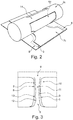
- FIG. 1 shows a rolling device 1, of which only top rollers 2 shown.
- the top rollers and bottom rollers form in the rolling direction (arrow 3) successive groups 4 of top and bottom rollers. Between the top rollers 2 and the bottom rollers, a nip is formed, in which a metal strip 5 passes.
- the top rollers 2, but also the bottom rollers have a profiling 6, which varies in shape as seen in the rolling direction 3, wherein the volume remains the same.
- the profiles 6 are referred to in the rolling direction 3 in the plane of the drawing from left to right with 6a, 6b and 6c.
- the first upper roller 2a seen in the rolling direction 3 has a deeper but narrower profiling 6a than the upper roller 2b following in the rolling direction 3.
- Their profiling 6b of the top roller 2b is in turn deeper and narrower than the profiling 6c of the top roller 2c which in turn follows in the rolling direction 3.
- top rollers 2 project laterally beyond the metal strip 5 along the rolling direction 3. The same applies to the lower rollers concerned.
- contours 7 are generated in the metal strip 5, which are designated in the rolling direction 3 in the plane of the drawing from left to right with the reference numerals 7a, 7b and 7c.
- the contours 7a and / b are intended to be part contours 7a and 7b, wherein the contour 7c can be referred to as end contour 7c.
- the metal strip 5 is seen in the rolling direction 3 continuously wider, but also thinner, which also applies to the contours 7a, 7b and 7c.
- a structural component for a motor vehicle can thus be produced in a rolling pass, which is weight-optimized and optimized in terms of load.
- the structural component can be designed in three dimensions, that is, have different thicknesses in each direction (X, Y, Z and / or oblique direction). This requires a particularly reduced material consumption, wherein the structural component in a rolling pass, for example in the configuration as a B-pillar quasi in its final form can be produced.
- a B-pillar is produced in a rolling pass, wherein only three groups 4 of top rollers 2 and bottom rollers are shown by way of example.
- the rolling means may also have more or less than three consecutive groups of rolls.
- an edge region, ie flange or connection surface 9, can be made very thin, so that a welding connection of the structural component with other components by means of the RFSSW (Refill Friction Stir Spot Welding) can be carried out particularly advantageously.
- FIG. 3 the structural component 10 produced by the method according to the invention and with the rolling device 1 according to the invention is shown in the exemplary embodiment as a B-pillar, wherein a sheet is rolled with different thicknesses both in the longitudinal direction and in the transverse direction, this thickness distribution being arbitrary, ie optimized.
- the exemplary B-pillar in the selected supervision the edge region 9 and a gain region 11.
- the reinforcing region 11 has a contour which changes from the bottom to the top in the plane of the drawing.
- the contour can be optimized for crashes but also optimized for weight, which means that over the plane seen in the drawing plane high-extension of the B-pillar areas in their material thickness are thicker than others, with intentional failure zones are provided in the event of a crash.
- a very thin edge region 9 can be produced, which significantly reduces the welding time by means of RFSSW.
- the arranged in the drawing plane for example, each below and above edge regions 9 are produced as welding flanges with a constant thickness, while the middle part has any, so optimized thickness distribution.
- the contour of the B-pillar may also have constrictions 12 in the reinforcing region 11, wherein not only with respect to the constrictions 12 are widenings 13 again configured.
- the B-pillar is as in FIG. 3 exemplified in a rolling pass with the rolling process and the rolling device 1 produced according to the invention, wherein still only a precise separation along the in FIG. 2 recognizable cutting edge 8 was performed from the metal strip.
- the cutting edge 8 is in FIG. 3 indicated.
- the metal band 5 may be a metal sheet or a light metal band such as an aluminum sheet.
- the profiling 6 is almost completely introduced into the top roller 2, that is also in the bottom roller. Only one transition bar 14 is provided.
- attachment elements such as flanges
- connection surface 9 of the metal strip 5 provided with the final contour 7c by means of welding methods.
- laser welding may be provided.
- This component can be solution annealed and quenched to the To be able to retain material properties, for example of the aluminum used as a material.
Landscapes
- Engineering & Computer Science (AREA)
- Mechanical Engineering (AREA)
- Physics & Mathematics (AREA)
- Geometry (AREA)
- Metal Rolling (AREA)
Claims (10)
- Procédé de fabrication d'un composant structurel (10), une bande métallique (5) étant laminée au moyen d'une pluralité de groupes (4) de rouleaux supérieurs et inférieurs disposés les uns derrières les autres dans une direction de laminage (3) de manière à produire la bande métallique (5) avec une épaisseur variable, des rouleaux supérieurs et/ou inférieurs de chaque groupe (4) étant pourvus de profils (6) de formes variables dans la direction de laminage (3), et la bande métallique préfabriquée (5) pourvue d'un contour final souhaité (7c) étant amenée à des étapes de traitement ultérieures
caractérisé en ce que
les profils respectifs (6) de formes variables de tous les groupes (4) ont un volume identique constant, la bande métallique (5) étant préfabriquée avec les contours partiels (7a, 7b) générés en raison des profils (6) de formes variables jusqu'au contour final souhaité (7c). - Procédé selon la revendication 1,
caractérisé en ce que
le contour d'extrémité (7c) de la bande métallique (5) est généré par un processus de laminage continu. - Procédé selon la revendication 1 ou 2,
caractérisé en ce que
la bande métallique préfabriquée (5) est enroulée en une bobine qui est acheminée vers les étapes de traitement ultérieures. - Procédé selon l'une des revendications précédentes,
caractérisé en ce que
la bande métallique (5) pourvue du contour final (7c) est mise en forme dans une autre étape de traitement ultérieure. - Procédé selon l'une des revendications précédentes,
caractérisé en ce que
la bande métallique (5) pourvue du contour final (7c) est durcie dans une autre étape de traitement ultérieure. - Procédé selon l'une des revendications précédentes,
caractérisé en ce que
la bande métallique (5) pourvue du contour final (7c) est découpée dans une étape de traitement ultérieure. - Procédé selon la revendication 6,
caractérisé en ce que
la bande métallique (5) pourvue du contour final (7c) est découpée dans une étape de traitement ultérieure de manière à ce que le contour d'extrémité (7c) soit découpé conjointement avec une surface de liaison (9). - Dispositif de laminage destiné à laminer une bande métallique (5), le dispositif comportant une pluralité de groupes de rouleaux supérieurs et inférieurs (4) disposés les uns derrière les autres dans une direction de laminage (3), la bande métallique (5) pouvant être produite avec une épaisseur variable, les rouleaux supérieurs et/ou inférieurs de chaque groupe (4) comportant des profils (6) de formes variables dans la direction de laminage (3),
caractérisé en ce que
les profils (6) de formes variables de tous les groupes ont un volume identique constant. - Dispositif de laminage selon la revendication 8,
caractérisé en ce que
le premier rouleau supérieur et/ou inférieur profilé, vu dans la direction de laminage (3), a un profil (6a) plus étroit mais plus profond que les rouleaux supérieurs et/ou inférieurs suivants des groupes suivants (4). - Dispositif de roulement selon la revendication 8 ou 9,
caractérisé en ce que
les profils (6) des rouleaux supérieurs et inférieurs, situés en aval d'un premier groupe (4) de rouleaux supérieurs et inférieurs, sont plus larges et moins profonds que les profils (6) des rouleaux supérieurs et inférieurs montés en amont dans la direction de laminage (3).
Applications Claiming Priority (1)
| Application Number | Priority Date | Filing Date | Title |
|---|---|---|---|
| DE102015204931 | 2015-03-19 |
Publications (2)
| Publication Number | Publication Date |
|---|---|
| EP3085471A1 EP3085471A1 (fr) | 2016-10-26 |
| EP3085471B1 true EP3085471B1 (fr) | 2019-10-02 |
Family
ID=55661185
Family Applications (1)
| Application Number | Title | Priority Date | Filing Date |
|---|---|---|---|
| EP16160667.8A Active EP3085471B1 (fr) | 2015-03-19 | 2016-03-16 | Procede de fabrication d'un composant structurel et dispositif de laminage correspondant |
Country Status (4)
| Country | Link |
|---|---|
| US (1) | US10518306B2 (fr) |
| EP (1) | EP3085471B1 (fr) |
| CN (1) | CN105983574B (fr) |
| DE (1) | DE102016200520B4 (fr) |
Families Citing this family (3)
| Publication number | Priority date | Publication date | Assignee | Title |
|---|---|---|---|---|
| ITUB20160442A1 (it) * | 2016-02-04 | 2017-08-04 | Fiat Ricerche | Procedimento per la laminazione di lamiere metalliche con spessore variabile |
| US20180169722A1 (en) * | 2016-12-15 | 2018-06-21 | GM Global Technology Operations LLC | Systems, methods and devices for 3d rolling of multi-gauge parts |
| JP6638639B2 (ja) * | 2016-12-19 | 2020-01-29 | トヨタ自動車株式会社 | 差厚金属板の製造方法、プレス部品の製造方法及び加工機 |
Family Cites Families (23)
| Publication number | Priority date | Publication date | Assignee | Title |
|---|---|---|---|---|
| US2184150A (en) * | 1935-07-31 | 1939-12-19 | Bard Parker Company Inc | Method of making rib-back blades |
| BE422326A (fr) * | 1937-01-26 | |||
| US3209432A (en) * | 1963-12-23 | 1965-10-05 | Ford Motor Co | Method for fabricating a structural member |
| US3877275A (en) * | 1973-08-22 | 1975-04-15 | Unistrut Corp | Cold roll reduction and forming method |
| DE2813636C3 (de) * | 1978-03-30 | 1980-10-30 | Theodor Wuppermann Gmbh, 5090 Leverkusen | Verfahren und Einrichtung zur Herstellung von Profilen aus Metall, vornehmlich von Stahlprofilen |
| US4279139A (en) * | 1979-07-02 | 1981-07-21 | Arbed Acieries Reunies De Burbach-Eich-Dudelange, Societe Anonyme | Method of rolling angle structural shapes |
| JPS56151130A (en) * | 1980-04-24 | 1981-11-24 | Tamagawa Kikai Kinzoku Kk | Method and apparatus for forming sheet of nonuniform section |
| JPH05123807A (ja) * | 1991-10-30 | 1993-05-21 | Hitachi Cable Ltd | ヒートシンク付きリードフレーム材の製造方法 |
| US5272899A (en) * | 1992-09-17 | 1993-12-28 | Mcdonald Steel Corp. | Method and apparatus for hot roll forming inside U-shaped channel section |
| JP3277679B2 (ja) | 1994-04-15 | 2002-04-22 | ソニー株式会社 | 高能率符号化方法と高能率符号化装置及び高能率復号化方法と高能率復号化装置 |
| JPH07284873A (ja) * | 1994-04-18 | 1995-10-31 | Hitachi Cable Ltd | ヒートシンク付きリードフレーム材の製造方法 |
| US5941114A (en) * | 1994-07-19 | 1999-08-24 | Sumitomo Metal Industries, Ltd. | Rolling apparatus for producing angle from steel strip and method of rolling the angle using the same |
| JP3724135B2 (ja) * | 1996-10-31 | 2005-12-07 | 日立電線株式会社 | 異形断面条の製造方法 |
| DE19962754A1 (de) * | 1999-08-06 | 2001-02-15 | Muhr & Bender Kg | Verfahren zum flexiblen Walzen eines Metallbandes |
| US6705145B1 (en) * | 1999-11-19 | 2004-03-16 | Matsushita Electric Industrial Co., Ltd. | Method of processing bent and deformed portion of metal material |
| DE10113610C2 (de) * | 2001-03-20 | 2003-04-17 | Reiner Kopp | Verfahren und Walzvorrichtung zur Ausbildung von dickenprofiliertem einstückigem Walzgut |
| DE10246164B4 (de) * | 2002-10-02 | 2014-03-20 | Benteler Automobiltechnik Gmbh | Verfahren zum Herstellen von Strukturbauteilen |
| DE102005062063B3 (de) | 2005-12-22 | 2007-01-04 | Linde + Wiemann Gmbh Kg | Flachband und Profilteil aus Metall |
| DE102008020473A1 (de) * | 2008-04-23 | 2009-10-29 | Benteler Automobiltechnik Gmbh | Verfahren zur Herstellung von in der Dicke variierenden Blechplatinen |
| DE102009007926A1 (de) * | 2009-02-06 | 2010-08-19 | Benteler Automobiltechnik Gmbh | Verfahren zur Herstellung von umfangsseitig konturierten länglichen Formplatinen aus einem Metallstreifen |
| ATE541656T1 (de) | 2009-09-25 | 2012-02-15 | Dreistern Gmbh & Co Kg | Walzverfahren und walzvorrichtung zum herstellen eines metallbands mit einer über seine breite variierenden dicke |
| DE102011086813A1 (de) | 2011-11-22 | 2013-05-23 | Ford Global Technologies, Llc | Einstückiges Blechbauteil für ein Fahrzeug |
| AT512899B1 (de) * | 2012-11-15 | 2013-12-15 | Blum Gmbh Julius | Verfahren zur Herstellung eines Blechprofils für eine Schubladen-Ausziehführung |
-
2016
- 2016-01-18 DE DE102016200520.0A patent/DE102016200520B4/de active Active
- 2016-03-07 CN CN201610126244.3A patent/CN105983574B/zh active Active
- 2016-03-16 EP EP16160667.8A patent/EP3085471B1/fr active Active
- 2016-03-18 US US15/074,098 patent/US10518306B2/en active Active
Non-Patent Citations (1)
| Title |
|---|
| None * |
Also Published As
| Publication number | Publication date |
|---|---|
| US10518306B2 (en) | 2019-12-31 |
| DE102016200520A1 (de) | 2016-09-22 |
| CN105983574A (zh) | 2016-10-05 |
| DE102016200520B4 (de) | 2019-10-31 |
| EP3085471A1 (fr) | 2016-10-26 |
| US20160271663A1 (en) | 2016-09-22 |
| CN105983574B (zh) | 2019-12-10 |
Similar Documents
| Publication | Publication Date | Title |
|---|---|---|
| DE102009025821B4 (de) | Verfahren zur Herstellung eines Metallbauteils | |
| EP3265365B1 (fr) | Pièce profilée en tôle trempée à la presse ayant différentes épaisseurs et rigidités | |
| DE102014110320B4 (de) | Verfahren zur Herstellung eines Leichtmetall Blechbauteils | |
| DE102008044523B4 (de) | Warmumformprofile | |
| DE10041280C2 (de) | Verfahren und Vorrichtung zum flexiblen Walzen eines Metallbandes | |
| EP2313216B1 (fr) | Procédé de fabrication d'un profilé laminé à froid présentant au moins un bord profilé épaissi | |
| DE10113610C2 (de) | Verfahren und Walzvorrichtung zur Ausbildung von dickenprofiliertem einstückigem Walzgut | |
| EP3195947A1 (fr) | Procédé de production d'un composant de véhicule automobile à partir d'un profilé métallique léger extrudé | |
| DE69425154T2 (de) | Warmgewalzter hubbalken und verfahren zur herstellung | |
| DE69527143T2 (de) | Walzwerk zur herstellung von winkelstahl aus bandstahl | |
| EP3085471B1 (fr) | Procede de fabrication d'un composant structurel et dispositif de laminage correspondant | |
| DE2940473A1 (de) | Verfahren und vorrichtung zur herstellung von metallprofilen | |
| DE10303184B3 (de) | Verfahren und Vorrichtung zur Herstellung von einer in ihrer Dicke mindestens in einem Bereich variierenden Platine | |
| DE102016103539B4 (de) | Verfahren zur Herstellung eines mehrdimensional gefügestrukturierten, tiefziehfähigen Metallflachprodukts und Metallflachprodukt | |
| DE102009053534B4 (de) | Vorrichtung und Verfahren zum Umformen und/oder Vergüten von Blechbauteilen sowie damit hergestelltes Blechformteil | |
| DE102009003655A1 (de) | Blechplatine mit homogenem Dickenübergang | |
| WO2005075279A1 (fr) | Element de construction a zone d'assemblage, procede et outil pour la fabrication dudit element | |
| DE112006003562B4 (de) | Verfahren zum Verbinden hoch-kohlenstoffhaltigen Stahls zum Endlos-Warmwalzen | |
| EP3296104B1 (fr) | Procédé de fabrication d'un élément de carrosserie à tendance réduite à la fissuration | |
| EP2959985B1 (fr) | Poutre profilée en feuillard laminé à froid ayant une résistance à la flexion accrue et son procédé de production | |
| EP2208555B1 (fr) | Procédé de laminage et dispositif de laminage pour la fabrication d'une bande de métal ayant une épaisseur variant en largeur | |
| EP2875877B1 (fr) | Procédé de fabrication d'un profilé à section variable | |
| WO2019137910A1 (fr) | Procédé de fabrication d'un module en tôle d'acier | |
| WO2015197485A1 (fr) | Procédé de fabrication d'un rail profilé | |
| WO2020058038A1 (fr) | Support longitudinal pour un véhicule routier |
Legal Events
| Date | Code | Title | Description |
|---|---|---|---|
| PUAI | Public reference made under article 153(3) epc to a published international application that has entered the european phase |
Free format text: ORIGINAL CODE: 0009012 |
|
| AK | Designated contracting states |
Kind code of ref document: A1 Designated state(s): AL AT BE BG CH CY CZ DE DK EE ES FI FR GB GR HR HU IE IS IT LI LT LU LV MC MK MT NL NO PL PT RO RS SE SI SK SM TR |
|
| AX | Request for extension of the european patent |
Extension state: BA ME |
|
| 17P | Request for examination filed |
Effective date: 20170426 |
|
| RBV | Designated contracting states (corrected) |
Designated state(s): AL AT BE BG CH CY CZ DE DK EE ES FI FR GB GR HR HU IE IS IT LI LT LU LV MC MK MT NL NO PL PT RO RS SE SI SK SM TR |
|
| STAA | Information on the status of an ep patent application or granted ep patent |
Free format text: STATUS: REQUEST FOR EXAMINATION WAS MADE |
|
| GRAP | Despatch of communication of intention to grant a patent |
Free format text: ORIGINAL CODE: EPIDOSNIGR1 |
|
| STAA | Information on the status of an ep patent application or granted ep patent |
Free format text: STATUS: GRANT OF PATENT IS INTENDED |
|
| INTG | Intention to grant announced |
Effective date: 20190701 |
|
| GRAS | Grant fee paid |
Free format text: ORIGINAL CODE: EPIDOSNIGR3 |
|
| GRAA | (expected) grant |
Free format text: ORIGINAL CODE: 0009210 |
|
| STAA | Information on the status of an ep patent application or granted ep patent |
Free format text: STATUS: THE PATENT HAS BEEN GRANTED |
|
| AK | Designated contracting states |
Kind code of ref document: B1 Designated state(s): AL AT BE BG CH CY CZ DE DK EE ES FI FR GB GR HR HU IE IS IT LI LT LU LV MC MK MT NL NO PL PT RO RS SE SI SK SM TR |
|
| REG | Reference to a national code |
Ref country code: GB Ref legal event code: FG4D Free format text: NOT ENGLISH |
|
| REG | Reference to a national code |
Ref country code: CH Ref legal event code: EP Ref country code: AT Ref legal event code: REF Ref document number: 1185635 Country of ref document: AT Kind code of ref document: T Effective date: 20191015 |
|
| REG | Reference to a national code |
Ref country code: DE Ref legal event code: R096 Ref document number: 502016006855 Country of ref document: DE |
|
| REG | Reference to a national code |
Ref country code: IE Ref legal event code: FG4D Free format text: LANGUAGE OF EP DOCUMENT: GERMAN |
|
| REG | Reference to a national code |
Ref country code: NL Ref legal event code: MP Effective date: 20191002 |
|
| REG | Reference to a national code |
Ref country code: LT Ref legal event code: MG4D |
|
| PG25 | Lapsed in a contracting state [announced via postgrant information from national office to epo] |
Ref country code: FI Free format text: LAPSE BECAUSE OF FAILURE TO SUBMIT A TRANSLATION OF THE DESCRIPTION OR TO PAY THE FEE WITHIN THE PRESCRIBED TIME-LIMIT Effective date: 20191002 Ref country code: NO Free format text: LAPSE BECAUSE OF FAILURE TO SUBMIT A TRANSLATION OF THE DESCRIPTION OR TO PAY THE FEE WITHIN THE PRESCRIBED TIME-LIMIT Effective date: 20200102 Ref country code: BG Free format text: LAPSE BECAUSE OF FAILURE TO SUBMIT A TRANSLATION OF THE DESCRIPTION OR TO PAY THE FEE WITHIN THE PRESCRIBED TIME-LIMIT Effective date: 20200102 Ref country code: PT Free format text: LAPSE BECAUSE OF FAILURE TO SUBMIT A TRANSLATION OF THE DESCRIPTION OR TO PAY THE FEE WITHIN THE PRESCRIBED TIME-LIMIT Effective date: 20200203 Ref country code: SE Free format text: LAPSE BECAUSE OF FAILURE TO SUBMIT A TRANSLATION OF THE DESCRIPTION OR TO PAY THE FEE WITHIN THE PRESCRIBED TIME-LIMIT Effective date: 20191002 Ref country code: LV Free format text: LAPSE BECAUSE OF FAILURE TO SUBMIT A TRANSLATION OF THE DESCRIPTION OR TO PAY THE FEE WITHIN THE PRESCRIBED TIME-LIMIT Effective date: 20191002 Ref country code: PL Free format text: LAPSE BECAUSE OF FAILURE TO SUBMIT A TRANSLATION OF THE DESCRIPTION OR TO PAY THE FEE WITHIN THE PRESCRIBED TIME-LIMIT Effective date: 20191002 Ref country code: LT Free format text: LAPSE BECAUSE OF FAILURE TO SUBMIT A TRANSLATION OF THE DESCRIPTION OR TO PAY THE FEE WITHIN THE PRESCRIBED TIME-LIMIT Effective date: 20191002 Ref country code: NL Free format text: LAPSE BECAUSE OF FAILURE TO SUBMIT A TRANSLATION OF THE DESCRIPTION OR TO PAY THE FEE WITHIN THE PRESCRIBED TIME-LIMIT Effective date: 20191002 Ref country code: GR Free format text: LAPSE BECAUSE OF FAILURE TO SUBMIT A TRANSLATION OF THE DESCRIPTION OR TO PAY THE FEE WITHIN THE PRESCRIBED TIME-LIMIT Effective date: 20200103 Ref country code: ES Free format text: LAPSE BECAUSE OF FAILURE TO SUBMIT A TRANSLATION OF THE DESCRIPTION OR TO PAY THE FEE WITHIN THE PRESCRIBED TIME-LIMIT Effective date: 20191002 |
|
| PG25 | Lapsed in a contracting state [announced via postgrant information from national office to epo] |
Ref country code: CZ Free format text: LAPSE BECAUSE OF FAILURE TO SUBMIT A TRANSLATION OF THE DESCRIPTION OR TO PAY THE FEE WITHIN THE PRESCRIBED TIME-LIMIT Effective date: 20191002 Ref country code: HR Free format text: LAPSE BECAUSE OF FAILURE TO SUBMIT A TRANSLATION OF THE DESCRIPTION OR TO PAY THE FEE WITHIN THE PRESCRIBED TIME-LIMIT Effective date: 20191002 Ref country code: RS Free format text: LAPSE BECAUSE OF FAILURE TO SUBMIT A TRANSLATION OF THE DESCRIPTION OR TO PAY THE FEE WITHIN THE PRESCRIBED TIME-LIMIT Effective date: 20191002 Ref country code: IS Free format text: LAPSE BECAUSE OF FAILURE TO SUBMIT A TRANSLATION OF THE DESCRIPTION OR TO PAY THE FEE WITHIN THE PRESCRIBED TIME-LIMIT Effective date: 20200224 |
|
| PG25 | Lapsed in a contracting state [announced via postgrant information from national office to epo] |
Ref country code: AL Free format text: LAPSE BECAUSE OF FAILURE TO SUBMIT A TRANSLATION OF THE DESCRIPTION OR TO PAY THE FEE WITHIN THE PRESCRIBED TIME-LIMIT Effective date: 20191002 |
|
| PGFP | Annual fee paid to national office [announced via postgrant information from national office to epo] |
Ref country code: FR Payment date: 20200219 Year of fee payment: 5 |
|
| REG | Reference to a national code |
Ref country code: DE Ref legal event code: R097 Ref document number: 502016006855 Country of ref document: DE |
|
| PG2D | Information on lapse in contracting state deleted |
Ref country code: IS |
|
| PG25 | Lapsed in a contracting state [announced via postgrant information from national office to epo] |
Ref country code: DK Free format text: LAPSE BECAUSE OF FAILURE TO SUBMIT A TRANSLATION OF THE DESCRIPTION OR TO PAY THE FEE WITHIN THE PRESCRIBED TIME-LIMIT Effective date: 20191002 Ref country code: EE Free format text: LAPSE BECAUSE OF FAILURE TO SUBMIT A TRANSLATION OF THE DESCRIPTION OR TO PAY THE FEE WITHIN THE PRESCRIBED TIME-LIMIT Effective date: 20191002 Ref country code: RO Free format text: LAPSE BECAUSE OF FAILURE TO SUBMIT A TRANSLATION OF THE DESCRIPTION OR TO PAY THE FEE WITHIN THE PRESCRIBED TIME-LIMIT Effective date: 20191002 Ref country code: IS Free format text: LAPSE BECAUSE OF FAILURE TO SUBMIT A TRANSLATION OF THE DESCRIPTION OR TO PAY THE FEE WITHIN THE PRESCRIBED TIME-LIMIT Effective date: 20200202 |
|
| PLBE | No opposition filed within time limit |
Free format text: ORIGINAL CODE: 0009261 |
|
| STAA | Information on the status of an ep patent application or granted ep patent |
Free format text: STATUS: NO OPPOSITION FILED WITHIN TIME LIMIT |
|
| PG25 | Lapsed in a contracting state [announced via postgrant information from national office to epo] |
Ref country code: SK Free format text: LAPSE BECAUSE OF FAILURE TO SUBMIT A TRANSLATION OF THE DESCRIPTION OR TO PAY THE FEE WITHIN THE PRESCRIBED TIME-LIMIT Effective date: 20191002 Ref country code: IT Free format text: LAPSE BECAUSE OF FAILURE TO SUBMIT A TRANSLATION OF THE DESCRIPTION OR TO PAY THE FEE WITHIN THE PRESCRIBED TIME-LIMIT Effective date: 20191002 Ref country code: SM Free format text: LAPSE BECAUSE OF FAILURE TO SUBMIT A TRANSLATION OF THE DESCRIPTION OR TO PAY THE FEE WITHIN THE PRESCRIBED TIME-LIMIT Effective date: 20191002 |
|
| 26N | No opposition filed |
Effective date: 20200703 |
|
| PG25 | Lapsed in a contracting state [announced via postgrant information from national office to epo] |
Ref country code: MC Free format text: LAPSE BECAUSE OF FAILURE TO SUBMIT A TRANSLATION OF THE DESCRIPTION OR TO PAY THE FEE WITHIN THE PRESCRIBED TIME-LIMIT Effective date: 20191002 |
|
| REG | Reference to a national code |
Ref country code: CH Ref legal event code: PL |
|
| PG25 | Lapsed in a contracting state [announced via postgrant information from national office to epo] |
Ref country code: SI Free format text: LAPSE BECAUSE OF FAILURE TO SUBMIT A TRANSLATION OF THE DESCRIPTION OR TO PAY THE FEE WITHIN THE PRESCRIBED TIME-LIMIT Effective date: 20191002 |
|
| REG | Reference to a national code |
Ref country code: BE Ref legal event code: MM Effective date: 20200331 |
|
| PG25 | Lapsed in a contracting state [announced via postgrant information from national office to epo] |
Ref country code: LU Free format text: LAPSE BECAUSE OF NON-PAYMENT OF DUE FEES Effective date: 20200316 |
|
| PG25 | Lapsed in a contracting state [announced via postgrant information from national office to epo] |
Ref country code: IE Free format text: LAPSE BECAUSE OF NON-PAYMENT OF DUE FEES Effective date: 20200316 Ref country code: LI Free format text: LAPSE BECAUSE OF NON-PAYMENT OF DUE FEES Effective date: 20200331 Ref country code: CH Free format text: LAPSE BECAUSE OF NON-PAYMENT OF DUE FEES Effective date: 20200331 |
|
| PG25 | Lapsed in a contracting state [announced via postgrant information from national office to epo] |
Ref country code: BE Free format text: LAPSE BECAUSE OF NON-PAYMENT OF DUE FEES Effective date: 20200331 |
|
| PG25 | Lapsed in a contracting state [announced via postgrant information from national office to epo] |
Ref country code: FR Free format text: LAPSE BECAUSE OF NON-PAYMENT OF DUE FEES Effective date: 20210331 |
|
| REG | Reference to a national code |
Ref country code: AT Ref legal event code: MM01 Ref document number: 1185635 Country of ref document: AT Kind code of ref document: T Effective date: 20210316 |
|
| PG25 | Lapsed in a contracting state [announced via postgrant information from national office to epo] |
Ref country code: TR Free format text: LAPSE BECAUSE OF FAILURE TO SUBMIT A TRANSLATION OF THE DESCRIPTION OR TO PAY THE FEE WITHIN THE PRESCRIBED TIME-LIMIT Effective date: 20191002 Ref country code: MT Free format text: LAPSE BECAUSE OF FAILURE TO SUBMIT A TRANSLATION OF THE DESCRIPTION OR TO PAY THE FEE WITHIN THE PRESCRIBED TIME-LIMIT Effective date: 20191002 Ref country code: CY Free format text: LAPSE BECAUSE OF FAILURE TO SUBMIT A TRANSLATION OF THE DESCRIPTION OR TO PAY THE FEE WITHIN THE PRESCRIBED TIME-LIMIT Effective date: 20191002 |
|
| PG25 | Lapsed in a contracting state [announced via postgrant information from national office to epo] |
Ref country code: MK Free format text: LAPSE BECAUSE OF FAILURE TO SUBMIT A TRANSLATION OF THE DESCRIPTION OR TO PAY THE FEE WITHIN THE PRESCRIBED TIME-LIMIT Effective date: 20191002 |
|
| PG25 | Lapsed in a contracting state [announced via postgrant information from national office to epo] |
Ref country code: AT Free format text: LAPSE BECAUSE OF NON-PAYMENT OF DUE FEES Effective date: 20210316 |
|
| P01 | Opt-out of the competence of the unified patent court (upc) registered |
Effective date: 20230620 |
|
| PGFP | Annual fee paid to national office [announced via postgrant information from national office to epo] |
Ref country code: DE Payment date: 20250210 Year of fee payment: 10 |
|
| PGFP | Annual fee paid to national office [announced via postgrant information from national office to epo] |
Ref country code: GB Payment date: 20250213 Year of fee payment: 10 |