EP3085658B1 - Verfahren und anordnung zur automatischen aufzugsinstallation - Google Patents
Verfahren und anordnung zur automatischen aufzugsinstallation Download PDFInfo
- Publication number
- EP3085658B1 EP3085658B1 EP15164766.6A EP15164766A EP3085658B1 EP 3085658 B1 EP3085658 B1 EP 3085658B1 EP 15164766 A EP15164766 A EP 15164766A EP 3085658 B1 EP3085658 B1 EP 3085658B1
- Authority
- EP
- European Patent Office
- Prior art keywords
- elevator shaft
- guide rails
- total station
- elevator
- reflectors
- Prior art date
- Legal status (The legal status is an assumption and is not a legal conclusion. Google has not performed a legal analysis and makes no representation as to the accuracy of the status listed.)
- Not-in-force
Links
- 238000009434 installation Methods 0.000 title claims description 102
- 238000000034 method Methods 0.000 title claims description 19
- 238000005259 measurement Methods 0.000 claims description 21
- 238000005452 bending Methods 0.000 claims description 2
- 230000032258 transport Effects 0.000 description 4
- 238000004891 communication Methods 0.000 description 3
- 238000005096 rolling process Methods 0.000 description 3
- 229910000831 Steel Inorganic materials 0.000 description 2
- 238000010276 construction Methods 0.000 description 2
- 239000007787 solid Substances 0.000 description 2
- 239000010959 steel Substances 0.000 description 2
- 239000000853 adhesive Substances 0.000 description 1
- 230000001070 adhesive effect Effects 0.000 description 1
- XAGFODPZIPBFFR-UHFFFAOYSA-N aluminium Chemical compound [Al] XAGFODPZIPBFFR-UHFFFAOYSA-N 0.000 description 1
- 229910052782 aluminium Inorganic materials 0.000 description 1
- 239000004411 aluminium Substances 0.000 description 1
- 238000005553 drilling Methods 0.000 description 1
- 238000005516 engineering process Methods 0.000 description 1
- 238000007667 floating Methods 0.000 description 1
Images


Classifications
-
- B—PERFORMING OPERATIONS; TRANSPORTING
- B66—HOISTING; LIFTING; HAULING
- B66B—ELEVATORS; ESCALATORS OR MOVING WALKWAYS
- B66B19/00—Mining-hoist operation
-
- B—PERFORMING OPERATIONS; TRANSPORTING
- B66—HOISTING; LIFTING; HAULING
- B66B—ELEVATORS; ESCALATORS OR MOVING WALKWAYS
- B66B9/00—Kinds or types of lifts in, or associated with, buildings or other structures
-
- B—PERFORMING OPERATIONS; TRANSPORTING
- B66—HOISTING; LIFTING; HAULING
- B66B—ELEVATORS; ESCALATORS OR MOVING WALKWAYS
- B66B19/00—Mining-hoist operation
- B66B19/002—Mining-hoist operation installing or exchanging guide rails
-
- B—PERFORMING OPERATIONS; TRANSPORTING
- B66—HOISTING; LIFTING; HAULING
- B66B—ELEVATORS; ESCALATORS OR MOVING WALKWAYS
- B66B11/00—Main component parts of lifts in, or associated with, buildings or other structures
-
- B—PERFORMING OPERATIONS; TRANSPORTING
- B66—HOISTING; LIFTING; HAULING
- B66B—ELEVATORS; ESCALATORS OR MOVING WALKWAYS
- B66B19/00—Mining-hoist operation
- B66B19/06—Applications of signalling devices
-
- B—PERFORMING OPERATIONS; TRANSPORTING
- B66—HOISTING; LIFTING; HAULING
- B66B—ELEVATORS; ESCALATORS OR MOVING WALKWAYS
- B66B7/00—Other common features of elevators
- B66B7/02—Guideways; Guides
- B66B7/023—Mounting means therefor
- B66B7/027—Mounting means therefor for mounting auxiliary devices
Definitions
- the invention relates to a method and an arrangement for automatic elevator installation.
- An elevator comprises an elevator car, lifting machinery, ropes, and a counterweight.
- the elevator car is supported on a transport frame being formed by a sling or a car frame.
- the sling surrounds the elevator car.
- the lifting machinery moves the car upwards and downwards in a vertically extending elevator shaft.
- the sling and thereby also the elevator car are carried by the ropes, which connect the elevator car to the counterweight.
- the sling is further supported with gliding means at guide rails extending in the vertical direction in the elevator shaft.
- the gliding means can comprise rolls rolling on the guide rails or gliding shoes gliding on the guide rails when the elevator car is mowing upwards and downwards in the elevator shaft.
- the guide rails are supported with fastening means on the side wall structures of the elevator shaft.
- the gliding means engaging with the guide rails keep the elevator car in position in the horizontal plane when the elevator car moves upwards and downwards in the elevator shaft.
- the counterweight is supported in a corresponding way on guide rails supported with fastening means on the wall structure of the elevator shaft.
- the elevator car transports people and/or goods between the landings in the building.
- the elevator shaft can be formed so that one or several of the side walls are formed of solid walls and/or so that one or several of the side walls are formed of an open steel structure.
- the guide rails are formed of guide rail elements of a certain length.
- the guide rail elements are connected in the installation phase end-on-end one after the other in the elevator shaft.
- the guide rails are attached to the walls of the elevator shaft with fastening means at fastening points along the height of the guide rails.
- WO publication 2007/135228 discloses a method for installing the guide rails of an elevator.
- a first pair of opposite car guide rail elements is installed starting from the bottom of the elevator shaft.
- a second pair of opposite car guide rails is installed end-on-end with the first pair of opposite car guide rails. The process is continued until all the pairs of opposite car guide rails have been installed.
- the counterweight guide rails are installed in a corresponding manner.
- a laser transmitter is used in connection with each guide rail to align the guide rail in the vertical direction.
- a self-directional laser could be used, which automatically directs the laser beam vertically upwards.
- the laser transmitters are first positioned at the bottom of the elevator shaft when the lowermost section of guide rails is installed.
- An alignment appliance provided with an alignment element is supported on each guide rail at each position where the alignment of the guide rail is to be done.
- the laser beam hits the alignment element, whereby the guide rail can be aligned so that the hitting point of the laser beam is in the middle of the alignment element.
- the laser transmitters are moved stepwise upwards for alignment of the next section of guide rails.
- WO publication 2014/053184 discloses a guide rail straightness measuring system for elevator installations.
- the measuring system comprises at least one plumb line mounted vertically in the elevator shaft adjacent to the guide rail and at least one sensor arrangement to be mounted on a carrier to travel vertically along the guide rail.
- the sensor arrangement comprises a frame, at least one guide shoe connected to the frame for sliding or rolling along the guide surface of the guide rail, a bias means for placing and biasing the frame against the guide surface, and at least one sensor means for sensing the position of the plumb line with respect to the frame.
- Publication JP H09-221288 discloses an arrangement with an installation platform for aligning guide rails by use of laser beams.
- An object of the present invention is to present a novel method for automatic elevator installation.
- the method for automatic elevator installation comprises the steps of:
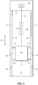
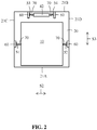
- Figure 1 shows a vertical cross section and figure 2 shows a horizontal cross section of an elevator.
- the elevator comprises a car 10, an elevator shaft 20, a machine room 30, lifting machinery 40, ropes 41, and a counter weight 42.
- the car 10 may be supported on a transport frame 11 or a sling surrounding the car 10.
- the lifting machinery 40 moves the car 10 in a first direction S1 upwards and downwards in a vertically extending elevator shaft 20.
- the sling 11 and thereby also the elevator car 10 are carried by the ropes 41, which connect the elevator car 10 to the counter weight 42.
- the sling 11 and thereby also the elevator car 10 is further supported with gliding means 70 at guide rails 50 extending in the vertical direction in the elevator shaft 20.
- the elevator shaft 20 has a bottom 12, a top 13, a front wall 21A, a back wall 21B, a first side wall 21C and a second opposite side wall 21D.
- the gliding means 70 can comprise rolls rolling on the guide rails 50 or gliding shoes gliding on the guide rails 50 when the elevator car 10 is mowing upwards and downwards in the elevator shaft 20.
- There are further two counter weight guide rails 53, 54 positioned at the back wall 21 B of the elevator shaft 20.
- the counter weight 42 is supported with corresponding gliding means 70 on the counter weight guide rails 53, 54.
- the landing doors (not shown in the figure) are positioned in connection with the front wall 21A of the elevator shaft 20.
- Each car guide rail 51, 52 is fastened with fastening means 60 at the respective side wall 21C, 21D of the elevator shaft 20 along the height of the car guide rail 51, 52.
- Each counter weight guide rail 53, 54 is fastened with corresponding fastening means 60 at the back wall 21B of the elevator shaft 20 along the height of the counter weight guide rail 53, 54.
- the figure shows only two fastening means 60, but there are several fastening means 60 along the height of each guide rail 50.
- the cross section of the guide rails 50 can have the form of a letter T.
- the vertical branch of the guide rail element 50 forms three gliding surfaces for the gliding means 70 comprising rolls or gliding shoes.
- the cross-section of the gliding means 70 can have the form of a letter U so that the inner surface of the gliding means 70 sets against the three gliding surfaces of the guide rail 50.
- the gliding means 70 are attached to the sling 11 and/or to the counter weight 42.
- the gliding means 70 engage with the guide rails 50 and keep the elevator car 10 and/or the counter weight 42 in position in the horizontal plane when the elevator car 10 and/or the counter weight 42 moves upwards and downwards in the first direction S1 in the elevator shaft 20.
- the elevator car 10 transports people and/or goods between the landings in the building.
- the elevator shaft 20 can be formed so that all side walls 21, 21A, 21B, 21C, 21D are formed of solid walls or so that one or several of the side walls 21, 21A, 21B, 21C, 21D are formed of an open steel structure.
- the guide rails 50 extend vertically along the height of the elevator shaft 20.
- the guide rails 50 are thus formed of guide rail elements of a certain length e.g. 5 m.
- the guide rail elements 50 are installed end-on-end one after the other.
- Figure 1 shows a first direction S1, which is a vertical direction in the elevator shaft 20.
- Figure 2 shows a second direction S2, which is the direction between the first side wall 21C and the second side wall 21D in the elevator shaft 20 i.e. the direction between the guide rails (DBG).
- Figure 2 shows further a third direction S3, which is the direction between the back wall 21B and the front wall 21A in the elevator shaft 20 i.e. the back to front direction (BTF).
- the second direction S2 is perpendicular to the third direction S3.
- the second direction S2 and the third direction S3 form a coordinate system in a horizontal plane in the elevator shaft 20.
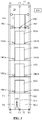
- Figure 3 shows a vertical cross section of an elevator shaft showing the principle of the invention.
- the idea is as a first step to measure the dimensions of the empty elevator shaft 20 with a robotic total station 600. Different positions in the empty elevator shaft are marked with reflectors so that the position of each reflector can be measured with the robotic total station 600.
- the reflectors can be disposable reflective sheet targets or prisms.
- the disposable reflective sheet targets are rather cheap and can be left on the target once the measurement has been done.
- the prisms are on the other hand expensive and cannot be left on the target after the measurement has been done.
- Each door opening DO1-D04 in the elevator shaft 20 is marked with downwards facing door reflectors DR1a-DR4a, DR1b-DR4b positioned at opposite sides of the door opening DO1-DO4.
- the door reflectors DR1 a-DR4a, DR1b-DR4b can be mounted e.g. on L-shaped support brackets of thin aluminium that are attached to the wall of the elevator shaft 20.
- Each door reflector DR1 a-DR4a, DR1 b-DR4b must be facing downwards in the elevator shaft 20.
- a robotic total station 600 is installed at a bottom 12 of the elevator shaft 20 and a reference coordinate system K0 of the elevator shaft 20 is created with the robotic total station 600. This can be done so that reflectors are positioned on different positions on the walls of the elevator shaft 20.
- the origin of the reference coordinate system K0 and the zero position of the horizontal angle i.e. the orientation of the X-axis are first defined with the robotic total station 600.
- the position of each of the reflectors on the walls of the elevator shaft 20 is then measured with the robotic total station 600.
- the position of the walls of the elevator shaft 20 are then determined with the robotic total station 600.
- the reflectors are left on the walls of the elevator shaft 20.
- the robotic total station 600 can be removed from the elevator shaft 20 and put again back in the elevator shaft 20 at any time.
- the robotic total station 600 can determine its own position in the reference coordinate system K0 in the elevator shaft 20 based on the position of the reflectors on the walls of the elevator shaft 20. If the coordinates of at least two points in the elevator shaft 20 are already known, then these points could be used to initially orientate the robotic total station 600.
- the position of each of the door reflectors DR1a-DR4a, DR1b-DR4b is measured with the robotic total station 600.
- the robotic total station 600 is directed to each door reflector DR1 a-DR4a, DR1 b-DR4b one at a time in order to perform the measurement.
- the robotic total station 600 is positioned in the same position in the elevator shaft 20 during the measurement. There must be full visibility from the robotic total station 600 to each of the door reflectors DR1a-DR4a, DR1b-DR4b.
- Straight door lines DL1, DL2 are then fitted to the measurements. These vertical straight door lines DL1, DL2 are used as virtual plumb lines for the installation of the doors in the elevator shaft 20.
- each guide rail 51, 52, 53, 54 is marked by points A2, B2 on the bottom 12 of the elevator shaft 20 in the coordinate system K0 of the elevator shaft 20.
- a vector passing between the points A2, B2 specifies the orientation of the guide rails 51, 52, 53, 54 i.e. the rotation of the guide rails 51, 52, 53, 54 around the Z-axis.
- These points A2, B2 are the target points for the automatic installation of the guide rails 51, 52, 53, 54 in the coordinate system K0 of the elevator shaft 20.
- the position is selected based on drawings showing the position of the guide rails 51, 52, 53, 54 within a horizontal cross section of the elevator shaft 20.
- the lowermost guide rails 51, 52, 53, 54 are mounted manually to the elevator shaft 20 based on the points A2, B2.
- Guide rail lines GL1, GL2 can be formed with the robotic total station 600 for the guide rails 51, 52, 53, 54 in the elevator shaft 20. These guide rail lines GL1, GL2 are formed based on the door lines DL1, DL2. These vertical straight guide rail lines GL1, GL2 are used as virtual plumbing lines for the guide rails 51, 52, 53, 54.
- An upwards and downwards along the car guide rails 51, 52 movable installation platform 500 is provided in the elevator shaft 20.
- the installation platform 500 is provided with downwards facing platform reflectors PR1-PR3 on a bottom surface of the installation platform 500.
- the height position and the orientation of the installation platform 500 in relation to the reference coordinate system K0 is measured with the robotic total station 600 based on the position of the platform reflectors PR1-PR3 in relation to the elevator shaft 20.
- the platform reflectors PR1-PR3 can originally be positioned e.g. on a common horizontal plane on the bottom surface of the installation platform 500.
- the orientation of the installation platform 500 in relation to the vertical direction can be calculated based on the difference in the vertical height of the platform reflectors PR1-PR3.
- the position of the installation platform 500 in the second direction S2 and in the third direction S3 can be calculated based on the differences in the position of the platform reflectors PR1-PR3 in the horizontal direction in relation to the original position of the platform reflectors PR1-
- Different kinds of automated or partly automated installation equipment e.g. industry robots can be positioned on the installation platform 500.
- the installation equipment can perform e.g. the following tasks: drilling holes to the walls of the elevator shaft 20, attaching brackets to the holes, handling guide rails, joining guide rails to each other, attaching guide rails to the brackets, releasing and tightening bolts in the brackets, adjusting guide rails.
- the equipment could be stationary attached to the installation platform 500.
- the position of the equipment could in such case be determined based on the position of the installation platform 500.
- the equipment could on the other hand be movable attached to the installation platform 500.
- the position of the equipment on the installation platform 500 must in such case be measured i.e. there must be a sensor system continuously measuring the position of the movable equipment on the installation platform 500.
- a central computer 800 may be used to control and monitor the robotic total station 600 and/or the installation platform 500 and/or the installation equipment on the installation platform 500.
- Top reflectors A1, B1 could further be installed on the top 13 of the elevator shaft 20. These top reflectors A1, B1 would be positioned on a vertical straight line above the bottom reflectors A2, B2 positioned at the bottom 12 of the elevator shaft 20. Each top reflector A1, B1 is positioned on a common vertical straight line with the corresponding bottom reflector A2, B2 when the elevator shaft 20 is in an unbent state. The top reflectors A1, B1 will deviate from the common vertical straight line when the elevator shaft 20 bends due to e.g. heavy wind acting on the building.
- a predetermined bending curve can be fitted between the bottom reflectors A2, B2 and the top reflectors A2, B2 in order to correct the measurement values of the position of the installation platform 500 when the elevator shaft 20 is in a bended state.
- the top reflectors A1, B1 can be used only in case there is straight visibility from the robotic total station 600 to the top reflectors A1, B1.
- the installation platform 500 will in most cases restrict the visibility from the robotic total station 600 to the top reflectors A1, B1.
- the movements of the elevator shaft 20 can, nevertheless, be taken into account by measuring the position of the door reflectors DR1a-DR4a, DR1b, DR4b.
- the figure shows further a third door line DL0, which is a vertical centre line of the doors in the elevator shaft 20.
- the centre door line DL0 is not necessary needed, but it provides an additional virtual plumb line for the doors in the elevator shaft 20.
- the figure shows also three platform reflectors PR1-PR3.
- the platform reflector PR3 on the centre door line DL0 is not necessary needed. By using three platform reflectors PR1-PR3 it is possible to determine the position and the orientation of the installation platform 500 in the coordinate system K0 of the elevator shaft 20.
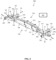
- Fig. 4 shows an axonometric view of an apparatus for aligning guide rails in an elevator shaft.
- the apparatus 400 for aligning guide rails 50 comprises a positioning unit 100 and an alignment unit 200.
- the apparatus 400 can be used by a mechanic or automatically on the installation platform 500 in order to align guide rails 51, 52, 53, 54.
- the positioning unit 100 comprises a longitudinal support structure with a middle portion 110 and two opposite end portions 120, 130.
- the two opposite end portions 120, 130 are mirror images of each other. There could be several middle portions 110 of different lengths in order to adjust the length of the positioning unit 100 to different elevator shafts 20.
- the positioning unit 100 comprises further first attachment means 140, 150 at both ends of the positioning unit 100.
- the first attachment means 140, 150 are movable in the second direction S2 i.e. the direction between the guide rails (DBG).
- the positioning unit 100 extends across the elevator shaft 20 in the second direction S2.
- the first attachment means 140, 150 are used to lock the positioning unit 100 between the wall structures 21 and/or dividing beams and/or brackets 60 in the elevator shaft 20.
- An actuator 141, 151 (position shown only schematically in the figure) e.g. a linear motor in connection with each of the first attachment means 140, 150 can be used to move each of the first attachment means 140, 150 individually in the second direction S2.
- the alignment unit 200 comprises a longitudinal support structure with a middle portion 210 and two opposite end portions 220, 230.
- the two opposite end portions 220, 230 are mirror images of each other.
- the alignment unit comprises further second attachment means 240, 250 at both ends of the alignment unit 200.
- the second attachment means 240, 250 are movable in the second direction S2.
- An actuator 241, 251 e.g. a linear motor can be used to move each of the second attachment means 240, 250 individually in the second direction S2.
- Each of the second attachment means 240, 250 comprises further gripping means in the form of jaws 245, 255 positioned at the end of the second attachment means 240, 250.
- the jaws 245, 255 are movable in the third direction S3 perpendicular to the second direction S2.
- the jaws 245, 255 will thus grip on the opposite side surfaces of the guide rails 50.
- An actuator 246, 256 e.g. a linear motor can be used to move each of the jaws 245, 255 individually in the third direction S3.
- the alignment unit 200 is attached to the positioning unit 100 at each end of the positioning unit 100 with support parts 260, 270.
- the support parts 260, 270 are movable in the third direction S3 in relation to the positioning unit 100.
- the alignment unit 200 is attached with articulated joints J1, J2 to the support parts 260, 270.
- An actuator 261, 271 e.g. a linear motor can be used to move each of the support parts 260, 270 individually in the third direction S3.
- the articulated joints J1, J2 make it possible to adjust the alignment unit 200 so that it is non-parallel to the positioning unit 100.
- the two second attachment means 240, 250 are moved with the actuators 241, 251 only in the second direction S2. It would, however, be possible to add a further actuator to one of the second attachment means 240, 250 in order to be able to turn said second attachment means 240, 250 in the horizontal plane around an articulated joint. It seems that such a possibility is not needed, but such a possibility could be added to the apparatus 500 if needed.
- the apparatus 400 can be operated by a mechanic or automatically by means of a control unit 300.
- the control unit 300 can be attached to the apparatus 400 or it can be a separate entity that is connectable with a cable to the apparatus 400. There can naturally also be a wireless communication between the control unit 300 and the apparatus 400.
- the control unit 300 is used to control all the actuators 141, 142 moving the first attachment means 140, 150, the actuators 241, 242 moving the second attachment means 240, 250, the actuators 246, 256 moving the gripping means 245, 255 and the actuators 261, 271 moving the support parts 260, 270.
- Figure 5 shows a first phase of the operation of the apparatus of figure 4 .
- the guide rails 51, 52 are attached to brackets 65, 66 and the brackets 65, 66 can be attached directly to the side wall 21C of the elevator shaft 20 or through a support bar 68 extending between the back wall 21 B and the front wall 21A of the elevator shaft 20.
- the bracket 65 is attached to a bar bracket 61 and the bar bracket 61 is attached to the support bar 68.
- the apparatus 400 can be supported on an installation platform and lifted with the installation platform to a height location of the first fastening means 60 during the alignment of the guide rails 50. A mechanic may be travelling on the installation platform.
- the apparatus 400 may be operated by a mechanic or automatically be means of the control unit 300 so that the alignment unit 200 is controlled to attach with the jaws 245, 255 at the ends of the second attachment means 240, 250 to the two opposite guide rails 51, 52.
- the second attachment means 240, 250 are movable in the second direction S2 and the jaws 245, 255 are movable in the third direction S3 so that they can grip on the opposite vertical side surfaces of the guide rails 51, 52.
- the bolts of the fastening means 60 are then opened at both sides of the elevator shaft 20 so that the guide rails 51, 52 can be moved.
- the guide rails 51, 52 on opposite sides of the elevator shaft 20 are then adjusted relative to each other with the alignment unit 200.
- the frame of the alignment unit 200 is stiff so that the two opposite guide rails 51, 52 will be positioned with the apexes facing towards each other when the gripping means 245, 255 grips the guide rails 50. There is thus no twist between the opposite guide rails 50 after this.
- the distance between the two opposite guide rails 50 in the direction (DBG) is also adjusted with the alignment unit 200.
- the position of each of the second attachment means 240, 250 in the second direction S2 determines said distance.
- GL1, GL2 shown in figure 3
- the distance in the DBG and the BTF direction from the guide rails 51, 52 to the respective plumb line GL1, GL2 that is in the vicinity of said guide rail 51, 52 is then determined.
- the needed control values (DBG, BTF and twist) for the apparatus 400 are then calculated.
- the control values are then transformed into incremental steps, which are fed as control signals to the control units of the linear motors in the apparatus 400.
- the DBG can also be measured based on the motor torque, which indicates when the second attachment means 240, 250 have reached their end position and are positioned against the guide rails 50.
- the position of the linear motors can then be read from the display of the control unit 300.
- the apparatus 400 can thus calculate the DBG based on the distance of the guide rails 51, 52 to the plumb lines and based on the position of each of the second attachment means 240, 250 in the second direction S2.
- Figure 6 shows a second phase of the operation of the apparatus of figure 4 .
- the positioning unit 100 of the apparatus 400 is locked to the wall constructions 21 or other support structures in the elevator shaft 20 with the first attachment means 140, 150.
- the alignment unit 200 of the apparatus 400 is in a floating mode in relation to the positioning unit 100 when the positioning unit 100 is locked to the wall construction 21 of the elevator shaft 20.
- the guide rails 51, 52 can now be adjusted with the alignment unit 200 and the positioning unit 100 in relation to the elevator shaft 20.
- the bolts of the fastening means 60 are then tightened.
- the apparatus 400 can now be transported to the next location of the fastening means 60 where the first phase and the second phase of the operation of the apparatus 400 is repeated.
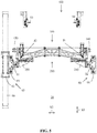
- Figure 7 shows an axonometric view of an elevator shaft with the apparatus of figure 4 on an installation platform.
- the figure shows the car guide rails 51, 52, the installation platform 500 and the apparatus 400 for aligning the guide rails 51, 52.
- the apparatus 400 for aligning the guide rails 51, 52 is attached with a support arm 450 to a support frame 460 and the support frame 460 is attached to the installation platform 500.
- the apparatus 400 for aligning the guide rails 51, 52 has to be movable in the second direction S2 and in the third direction S3 in relation to the installation platform 500. This can be achieved with one or several joints J10 in the support arm 450.
- the support frame 460 can also be arranged to be movable in the second direction S2 and in the third direction S3.
- the position of the support arm 450 on the installation platform 500 can be measured by sensors arranged in connection with the support frame 460 and/or the support arm 450.
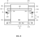
- Figure 8 shows a horizontal cross section of the elevator shaft with the apparatus of figure 4 on an installation platform.
- the figure shows the installation platform 500, the apparatus 400 for aligning guide rails and three platform reflectors PR1, PR2, PR3 supported on a bottom of the installation platform 500.
- the installation platform 500 comprises support arms 510, 520, 530, 540 arranged on opposite sides of the installation platform 500 and being movable in a second direction S2 for supporting the installation platform 500 on the opposite side walls 21C, 21D of the elevator shaft 20.
- the gripping means 245, 255 of the second attachment means 240, 250 can grip the opposite guide surfaces of the car guide rails 51, 52.
- the car guide rails 51, 52 can thus be aligned with the apparatus 400 for alignment of guide rails as described earlier in connection with figures 4-6 .
- the installation platform 500 is locked in place with the support arms 510, 520, 530, 540.
- the position of the installation platform 500 in relation to the elevator shaft 20 is determined with the robotic total station 600 positioned at the bottom 12 of the elevator shaft 20 based on the position of the platform reflectors PR1-PR3 once the installation platform 500 is locked in the elevator shaft 20.
- the coordinates of the stationary installation platform 500 in relation to the elevator shaft 20 are determined, then it is possible to determine the coordinates of the alignment apparatus 400 in relation to the installation platform 500 continuously during the alignment procedure.
- the alignment apparatus 400 is movably attached to the installation platform 500, whereby the position of the alignment apparatus 400 in relation to the elevator shaft 20 can be determined indirectly based on the position of the installation platform 500 in relation to the elevator shaft 20.
- the position of the alignment apparatus 400 on the installation platform 500 can be measured with sensors measuring the position of the support frame 460 and/or the support arm 450.
- the position of the guide rails 51, 52 can be determined indirectly based on the position of the apparatus 400.
- the alignment apparatus 400 could on the other hand be stationary attached to the installation platform 500.
- the position of the alignment apparatus 400 would in such case remain stationary on the installation platform 500.
- the position of the gripping means 245, 255 could then be determined in relation to the stationary attachment point of the alignment apparatus 400 on the installation platform 500.
- the installation platform 500 may be provided with different installation equipment in addition to the apparatus 400 for aligning guide rails.
- the installation equipment may be used to install doors and guide rails.
- the installation equipment may comprise one or several robots being stationary or movable on the installation platform 500.
- the installation platform 500 may be supported with gliding means on the opposite car guide rails 51, 52 during the movement in the first direction S1 upwards and downwards in the elevator shaft 20.
- a hoist may be used to move the installation platform 500 in the first direction S1 upwards and downwards in the elevator shaft 20.
- the position of the first guide rails 51, 52, 53, 54 at the bottom 12 of the elevator shaft 20 are marked on the bottom 12 of the elevator shaft based on the dimensions of the elevator shaft 20, the elevator car 10 and the counter weight 42.
- the first car guide rails 51, 52, 53, 54 at the bottom 12 of the elevator shaft 20 are thereafter installed manually to the elevator shaft 20.
- the installation platform 500 can then be installed to the elevator shaft 20 so that the installation platform 500 glides on the car guide rails 51, 52 when the hoist moves the installation platform 500 upwards and downwards in the elevator shaft 20.
- the doors and the further guide rails 51, 52, 53, 54 can thereafter be installed into the elevator shaft 20 with the installation platform 500.
- the alignment of the guide rails 51, 52, 53, 54 can be done as a separate process after the guide rails 51, 52, 53, 54 have been erected.
- the transfer of information and control data between the robotic total station 600 and the control unit 300 and the computer 800 may be by wireless communication or by wire.
- the transfer of information and control data between the installation platform 500 and the control unit 300 and between the apparatus for alignment 400 and the control unit 300 may be by wireless communication or by wire.
- the robotic total station 600 should be capable of a long range if it is used in a high-rise building.
- a robotic total station 600 is a general purpose 3D positioning device commonly used in civil engineering and industrial measurements.
- a robotic total station is a device measuring positions of points in relation to the device in polar coordinates. The device operates in a polar coordinate system, but the results are calculated by standard trigonometry into a right-angled X-, Y-, Z- coordinate system.
- the robotic total station measures the horizontal angle, the vertical angle and the distance (slope distance) to the target. Encoders are used for measuring the horizontal angle and the vertical angle and a laser based distance sensor is used for measuring the distance.
- a robotic total station gives the X-, Y- and Z-coordinates of the target to be measured.
- the target to be measured is marked either with a prism or with a reflective sheet target that can be attached with an adhesive.
- the results of the measurements are added to the position of the robotic position, which has been determined in an initial orientation of the robotic total station.
- the initial orientation of the robotic total station means that the robotic total station is set to be ready to perform measurements. If there are reference points with known coordinates in the environment of the robotic total station, then two or more of these reference points are pointed out to the robotic total station.
- the robotic total station can based on the coordinates of these reference points determine its own position in said coordinate system.
- a robotic total station can be operated by a computer i.e. the device can be remote driven by a computer.
- the robotic total station comprises thus servo motors by means of which the robotic total station can be directed towards the targets to be measured.
- Robotic total stations are manufactured e.g. by Leica Geosystems, Sokkia, Trimble and Topcon. Leica TS30 has been tested in an elevator shaft and it seems to work well also in vertical measurements.
- the robotic total station 600 could be operated manually by a mechanic at the bottom 12 of the elevator shaft 20.
- the aiming of the robotic total station 600 can be done by a red laser dot and a telescope of the robotic total station.
- An additional eyepiece is used to be able to do the measurements in an upwards direction.
- the robotic total station 600 could also be operated automatically with the aid of a remotely located computer. There could be a wireless connection or a connection by wire between the robotic total station 600 and the computer.
- the coarse position of the reflectors in the elevator shaft 20 are known, which means that it is possible to instruct the robotic total station 600 to aim at a given direction and to find the reflector in said direction.
- the arrangement and the method can be used in elevator installations where the hoisting height in the elevator shaft is over 30 mm, preferably 30-80 meters, most preferably 40-80 meters.
- the arrangement and the method can on the other hand also be used in elevator installations where the hoisting height in the elevator shaft is over 75 meters, preferably over 100 meters, more preferably over 150 meters, most preferably over 250 meters.
- the installation platform 500 can be used to install car guide rails 51, 52 and/or counter weight guide rails 53, 54.
- the use of the invention is not limited to the type of elevator disclosed in the figures.
- the invention can be used in any type of elevator e.g. also in elevators lacking a machine room and/or a counterweight.
- the counterweight is in the figures positioned on the back wall of the elevator shaft.
- the counterweight could be positioned on either side wall of the elevator shaft or on both side walls of the elevator shaft.
- the lifting machinery is in the figures positioned in a machine room at the top of the elevator shaft.
- the lifting machinery could be positioned at the bottom of the elevator shaft or at some point within the elevator shaft.
Landscapes
- Engineering & Computer Science (AREA)
- Structural Engineering (AREA)
- Civil Engineering (AREA)
- Mechanical Engineering (AREA)
- Automation & Control Theory (AREA)
- Lift-Guide Devices, And Elevator Ropes And Cables (AREA)
Claims (9)
- Verfahren zur automatischen Installation eines Aufzugs, gekennzeichnet durch die folgenden Schritte:Markieren jeder Türöffnung (DO1-DO4) in dem Aufzugschacht (20) mit nach unten gerichteten Tür-Reflektoren (DR1a-DR4a, DR1b-DR4b), die an einander gegenüberliegenden Seiten der Türöffnung (DO1-DO4) positioniert sind,Positionieren einer Roboter-Totalstation (600) an einem Boden (12) des Aufzugschachts (20) und Schaffen eines Bezugs-Koordinatensystems (K0) des Aufzugschachts (20) mit der Roboter-Totalstation (600),Messen der Position der Tür-Reflektoren (DR1a-DR4a, DR1b-DR4b) in Bezug auf den Aufzugschacht (20) mit der Roboter-Totalstation (600),Anlegen gerader Tür-Linien (DL1, DL2) an die Messungen, wobei die geraden Tür-Linien (DL1, DL2) virtuelle Lotrechte für die Türen in dem Aufzugschacht (20) bilden,Markieren der vorgegebenen Positionen (A2, B2) der Führungsschienen (51, 52, 53, 54) an dem Boden (12) des Aufzugschachts (20) auf Basis der Abmessungen des Aufzugschachts (20) und der Aufzugkabine (10),manuelles Installieren der untersten Führungsschienen (51, 52, 53, 54) an dem Aufzugschacht (20) auf Basis der vorgegebenen Positionen (A2, B2) der Führungsschienen (51, 52, 53, 54),Ausbilden vertikaler Führungsschienen-Linien (GL1, GL2) mit der Roboter-Totalstation (600) auf Basis der Tür-Linien (DL1, DL2), wobei die vertikalen Führungsschienen-Linien (GL1, GL2) virtuelle Lotrechte für die Führungsschienen (51, 52, 53, 54) in dem Aufzugschacht (20) bilden,Bereitstellen einer an den Kabinen-Führungsschienen (51, 52) nach oben und nach unten beweglichen Installations-Plattform (500) in dem Aufzugschacht (20),Positionieren nach unten gewandter Plattform-Reflektoren (PR1-PR3) an einer Unterseite der Installations-Plattform,Messen der Position der Plattform-Reflektoren (PR1-PR3) in Bezug auf den Aufzugschacht (20) mit der Roboter-Totalstation (600), so dass die Ausrichtung und die Position der Installations-Plattform (500) in Bezug auf den Aufzugschacht (20) bestimmt werden können.
- Verfahren nach Anspruch 1, gekennzeichnet durch den Schritt des Bereitstellens von Tragearmen (510, 520, 530, 540) an einander gegenüberliegenden Seiten der Installations-Plattform (500), wobei die Tragearme (510, 520, 530) von der Installations-Plattform (500) nach außen bewegt werden können, um die Installations-Plattform (500) an einander gegenüberliegenden Seitenwänden (21C, 21D) des Aufzugschachts (20) zu tragen.
- Verfahren nach Anspruch 1 oder 2, gekennzeichnet durch den Schritt des Bereitstellens einer Vorrichtung (400) zum Ausrichten von Führungsschienen an der Installations-Plattform (500), wobei die Vorrichtung umfasst:eine Positionier-Einheit (100), die sich in der zweiten Richtung (S2) horizontal über den Aufzugschacht (20) erstreckt und erste Anbringungseinrichtungen (140, 150) umfasst, die an jedem Ende der Positionier-Einheit (100) in der zweiten Richtung (S2) bewegt werden können, um die Positionier-Einheit (100) an den einander gegenüberliegenden Wandstrukturen (21) des Aufzugschachts (20) zu tragen,eine Ausricht-Einheit (200), die sich in der zweiten Richtung (S2) über den Aufzugschacht (20) erstreckt und mit Trageteilen (260, 270) an jedem Endabschnitt der Positionier-Einheit (100) getragen wird, so dass jeder Endabschnitt der Ausricht-Einheit (200) einzeln in einer dritten Richtung (S3) senkrecht zu der zweiten Richtung (S2) in Bezug auf die Positionier-Einheit (300) bewegt werden kann, und die zweite Anbringungseinrichtungen (240, 250) umfasst, die in der zweiten Richtung (S2) an jedem Ende der Ausricht-Einheit (200) bewegt werden können, um die Ausricht-Einheit (200) an einander gegenüberliegenden Führungsschienen (50) in dem Aufzugschacht (20) zu tragen, wobei die zweiten Anbringungseinrichtungen (240, 250) Klemmeinrichtungen (245, 255) zum Anklemmen an der Führungsschiene (50) umfassen.
- Verfahren nach einem der Ansprüche 1 bis 3, gekennzeichnet durch den Schritt des Bereitstellens nach unten gewandter Oberseiten-Reflektoren (A1, B1) an einer Oberseite (13) des Aufzugschachts (20) wobei die Messungen der Roboter-Totalstation (600) auf Basis der Bewegung der Oberseiten-Reflektoren (A1, B1) entsprechend der Biegung des Aufzugschachts (20) korrigiert werden, die durch Wind während der Messungen verursacht wird.
- Verfahren nach einem der Ansprüche 1 bis 4, gekennzeichnet durch den Schritt des Ausrichtens von Führungsschienen (51, 52, 53, 54) mittels einer Vorrichtung (400) zum Ausrichten von Führungsschienen, die an der Installations-Plattform (500) positioniert sind.
- Verfahren nach Anspruch 5, gekennzeichnet durch den Schritt des Anordnens einer Steuerungs-Einheit (300) zum Steuern der Vorrichtung (400) zum Ausrichten von Führungsschienen.
- Verfahren nach Anspruch 6, gekennzeichnet durch den Schritt des Verbindens der Roboter-Totalstation (600) und der Steuerungseinheit (300) zum Ermöglichen von Übertragung von Messungs- und/oder Steuerungssignalen zwischen ihnen.
- Anordnung zur automatischen Installation eines Aufzugs, wobei eine an den Kabinen-Führungsschienen (51, 52) nach oben und nach unten bewegliche Installations-Plattform (500) in dem Aufzugschacht (20) vorhanden ist,
dadurch gekennzeichnet, dass:nach unten gewandte Tür-Reflektoren (DR1a-DR4a, DR1b-DR4b) an einander gegenüberliegenden Seiten jeder Türöffnung (DO1-DO4) in dem Aufzugschacht (20) positioniert sind,nach unten gewandte Plattform-Reflektoren (PR1-PR3) an einer Unterseite der Installations-Plattform (500) positioniert sind,unterste Führungsschienen (51, 52, 53, 54) an vorgegebenen Positionen (A2, B2) am Boden des Aufzugschachts (20) positioniert sind, wobei die vorgegebenen Positionen (A2, B2) auf Basis der Abmessungen des Aufzugschachts (20) und der Aufzugkabine (10) bestimmt und markiert werden,eine Roboter-Totalstation (600) an einem Boden (12) des Aufzugschachts (20) positioniert ist, wobeiein Bezugs-Koordinatensystem (K0) des Aufzugschachts (20) mit der Roboter-Totalstation (600) geschaffen wird,die Position der Tür-Reflektoren (DR1a-DR4a, DR1b-DR4b) in Bezug auf den Aufzugschacht (20) mit der Roboter-Totalstation (600) gemessen wird,gerade Tür-Linien (DL1, DL2) an die Messungen mit der Roboter-Totalstation (600) angelegt werden, wobei die geraden Tür-Linien (DL1, DL2) virtuelle Lotrechte für die Türen in dem Aufzugschacht (20) bilden,vertikale Führungsschienen-Linien (GL1, GL2) mit der Roboter-Totalstation (600) auf Basis der Tür-Linien (DL1, DL2) ausgebildet werden, wobei die vertikalen Führungsschienen-Linien (GL1, GL2) virtuelle Lotrechte für die Führungsschienen (51, 52, 53, 54) in dem Aufzugschacht (20) bilden,die Position der Plattform-Reflektoren (PR1-PR3) in Bezug auf den Aufzugschacht (20) mit der Roboter-Totalstation (600) gemessen wird, so dass die Ausrichtung und die Position der Installations-Plattform (500) in Bezug auf den Aufzugschacht (20) bestimmt werden können. - Einsatz der Anordnung nach Anspruch 8 bei einer automatischen Installation eines Aufzugs.
Priority Applications (3)
| Application Number | Priority Date | Filing Date | Title |
|---|---|---|---|
| EP15164766.6A EP3085658B8 (de) | 2015-04-23 | 2015-04-23 | Verfahren und anordnung zur automatischen aufzugsinstallation |
| US15/092,248 US9561938B2 (en) | 2015-04-23 | 2016-04-06 | Method and an arrangement for automatic elevator installation |
| CN201610256946.3A CN106064776B (zh) | 2015-04-23 | 2016-04-22 | 用于自动电梯安装的方法和装置 |
Applications Claiming Priority (1)
| Application Number | Priority Date | Filing Date | Title |
|---|---|---|---|
| EP15164766.6A EP3085658B8 (de) | 2015-04-23 | 2015-04-23 | Verfahren und anordnung zur automatischen aufzugsinstallation |
Publications (3)
| Publication Number | Publication Date |
|---|---|
| EP3085658A1 EP3085658A1 (de) | 2016-10-26 |
| EP3085658B1 true EP3085658B1 (de) | 2017-08-16 |
| EP3085658B8 EP3085658B8 (de) | 2017-09-20 |
Family
ID=52997361
Family Applications (1)
| Application Number | Title | Priority Date | Filing Date |
|---|---|---|---|
| EP15164766.6A Not-in-force EP3085658B8 (de) | 2015-04-23 | 2015-04-23 | Verfahren und anordnung zur automatischen aufzugsinstallation |
Country Status (3)
| Country | Link |
|---|---|
| US (1) | US9561938B2 (de) |
| EP (1) | EP3085658B8 (de) |
| CN (1) | CN106064776B (de) |
Cited By (1)
| Publication number | Priority date | Publication date | Assignee | Title |
|---|---|---|---|---|
| WO2020120190A1 (de) | 2018-12-13 | 2020-06-18 | Inventio Ag | Verfahren zur zumindest teilweise automatisierten planung einer installation von aufzugkomponenten einer aufzuganlage |
Families Citing this family (34)
| Publication number | Priority date | Publication date | Assignee | Title |
|---|---|---|---|---|
| FI125266B (fi) * | 2013-06-07 | 2015-08-14 | Kone Oyj | Menetelmä hissin asennuksessa ja menetelmässä käytettävä työväline |
| EP2955145B1 (de) * | 2014-06-13 | 2016-12-21 | KONE Corporation | Vorrichtung und Verfahren zur Ausrichtung von Aufzugsführungsschienen |
| US9816796B2 (en) * | 2014-10-09 | 2017-11-14 | Wurtec, Incorporated | Guide rail straightness tester |
| CN107207196B (zh) * | 2015-02-04 | 2021-01-01 | 奥的斯电梯公司 | 电梯系统评估装置 |
| EP3090976B1 (de) * | 2015-05-06 | 2020-03-04 | KONE Corporation | Vorrichtung und verfahren zum ausrichten von führungsschienen und stockwerktüren in einem aufzugsschacht |
| DE112016002618T5 (de) * | 2015-06-09 | 2018-03-01 | Mitsubishi Electric Corporation | Messeinrichtung für Aufzugsschachtdimensionen und Messverfahren für Aufzugsschachtdimensionen |
| EP3127847B1 (de) * | 2015-08-07 | 2017-12-20 | KONE Corporation | Anordnung und verfahren zur messung der position einer anlagenplattform in einem aufzugsschacht |
| MX2018006622A (es) * | 2015-12-02 | 2018-08-01 | Inventio Ag | Monitoreo y/o registro de posicion de herramienta en caja de elevador. |
| EP3445697B1 (de) * | 2016-04-20 | 2020-01-22 | Inventio AG | Verfahren und montagevorrichtung zum durchführen eines installationsvorgangs in einem aufzugschacht einer aufzuganlage |
| US11235953B2 (en) * | 2017-03-27 | 2022-02-01 | Inventio Ag | Method and assembly device for carrying out an installation process in an elevator shaft of an elevator system |
| WO2019063277A1 (de) * | 2017-09-27 | 2019-04-04 | Inventio Ag | Lokalisierungssystem und verfahren zur bestimmung einer aktuellen position in einem aufzugschacht einer aufzuganlage |
| WO2019063356A1 (de) * | 2017-09-27 | 2019-04-04 | Inventio Ag | Ausrichtvorrichtung und verfahren zur montage einer führungsschiene in einem aufzugschacht einer aufzuganlage |
| EP3466859B1 (de) * | 2017-10-09 | 2023-11-29 | KONE Corporation | Führungsschienenausrichtungsverfahren und -anordnung |
| CN108132050B (zh) * | 2017-11-15 | 2020-07-03 | 上海建工集团股份有限公司 | 暗挖幕架体系监测系统和监测方法 |
| JP2020007095A (ja) * | 2018-07-06 | 2020-01-16 | 株式会社日立ビルシステム | エレベーター据付装置 |
| CN109205445B (zh) * | 2018-11-23 | 2019-08-02 | 燕山大学 | 一种用于安装电梯导轨的自爬升机器人 |
| US11059701B2 (en) * | 2018-12-06 | 2021-07-13 | Tk Elevator Innovation And Operations Gmbh | Methods and apparatuses for lifting elevator cars during installation |
| DE102019205555A1 (de) * | 2019-04-17 | 2020-06-18 | Thyssenkrupp Ag | Vorrichtung zur Justage und Montage von Aufzugkomponenten |
| CN109987478A (zh) * | 2019-04-18 | 2019-07-09 | 湖南电气职业技术学院 | 一种用于电梯导轨支架安装的辅助定位系统及方法 |
| WO2020234005A1 (de) * | 2019-05-21 | 2020-11-26 | Inventio Ag | Ausrichtvorrichtung und verfahren zum ausrichten einer führungsschiene einer aufzuganlage durch kraftimpulse |
| EP3766820B1 (de) | 2019-07-16 | 2023-05-31 | KONE Corporation | Verfahren und anordnung zur aufzugsführungsschieneninstallation |
| EP3766818B1 (de) * | 2019-07-16 | 2023-06-07 | KONE Corporation | Verfahren und anordnung zum installieren von aufzugsführungsschienen in einem aufzugsschacht |
| EP3766819B1 (de) * | 2019-07-16 | 2023-06-07 | KONE Corporation | Verfahren und anordnung zum installieren von aufzugsführungsschienen in einem aufzugsschacht |
| JP2021095257A (ja) * | 2019-12-18 | 2021-06-24 | 株式会社日立ビルシステム | エレベータのレール据付装置 |
| CN115279681B (zh) * | 2020-03-12 | 2024-08-16 | 因温特奥股份公司 | 在升降机竖井中形成引导升降机轿厢的引导结构的方法 |
| US11702316B2 (en) * | 2020-03-16 | 2023-07-18 | Otis Elevator Company | Elevator inspection system with robotic platform configured to develop hoistway model data from sensor data |
| US12358756B2 (en) | 2020-03-16 | 2025-07-15 | Otis Elevator Company | Elevator inspection system with robot configured to inspect operational conditions of elevator car |
| DE102020208583A1 (de) | 2020-07-08 | 2022-01-13 | Thyssenkrupp Elevator Innovation And Operations Gmbh | Vorrichtung zur Justage und Montage von Aufzugkomponenten |
| US12000689B2 (en) | 2020-08-17 | 2024-06-04 | Faro Technologies, Inc. | Environmental scanning and image reconstruction thereof |
| EP4271642A1 (de) * | 2020-12-29 | 2023-11-08 | KONE Corporation | Konstruktionsanordnung für einen aufzug |
| CN113277407B (zh) * | 2021-03-30 | 2022-11-15 | 广州明森合兴科技有限公司 | 一种底码自动安装设备及方法 |
| CN116062586A (zh) * | 2021-11-04 | 2023-05-05 | 奥的斯电梯公司 | 电梯导轨安装支架及其安装方法、定位工装、支架调整工装及电梯系统 |
| CN119317589A (zh) * | 2022-06-08 | 2025-01-14 | 因温特奥股份公司 | 电梯系统 |
| CN115162079A (zh) * | 2022-07-17 | 2022-10-11 | 中交第二航务工程局有限公司 | 无砟轨道精调在大风天气下防风罩及其无砟轨道精调方法 |
Family Cites Families (13)
| Publication number | Priority date | Publication date | Assignee | Title |
|---|---|---|---|---|
| GB2260963B (en) * | 1991-10-29 | 1994-09-21 | Otis Elevator Co | Elevator guide rail alignment |
| JPH09221288A (ja) * | 1996-02-16 | 1997-08-26 | Hitachi Building Syst Co Ltd | エレベータガイドレールの芯出し装置 |
| JPH1144095A (ja) * | 1997-07-30 | 1999-02-16 | Toda Constr Co Ltd | 建築用自動昇降装置と、自昇型養生ネット及び自昇型外部足場 |
| US5931264A (en) * | 1997-09-25 | 1999-08-03 | Otis Elevator Company | Rail survey unit |
| FI119983B (fi) * | 2006-05-24 | 2009-05-29 | Kone Corp | Menetelmä ja järjestelmä hissin johteiden asentamiseksi |
| US7886454B2 (en) * | 2008-12-31 | 2011-02-15 | Kone Corporation | Elevator hoistway installation guide systems, methods and templates |
| KR20100112855A (ko) * | 2009-04-10 | 2010-10-20 | (주)케이엠테크 | 자동 수직 적재 장치 |
| EP2424809B1 (de) * | 2009-04-29 | 2013-06-05 | Inventio AG | Markierungsvorrichtung in aufzugsanlage |
| CN101758116B (zh) * | 2009-12-31 | 2011-05-04 | 浙江大学 | T型导轨自动矫直装置 |
| CN102249129B (zh) * | 2011-05-30 | 2014-03-26 | 张凡 | 积木式加装电梯导轨 |
| CN104703905A (zh) * | 2012-10-04 | 2015-06-10 | 通力股份公司 | 用于电梯安装的导轨直线度测量系统 |
| EP2955145B1 (de) * | 2014-06-13 | 2016-12-21 | KONE Corporation | Vorrichtung und Verfahren zur Ausrichtung von Aufzugsführungsschienen |
| EP2993152B8 (de) * | 2014-09-04 | 2017-04-19 | KONE Corporation | Vorrichtung und Verfahren zum Ausrichten von Führungsschienen in einem Aufzugsschacht |
-
2015
- 2015-04-23 EP EP15164766.6A patent/EP3085658B8/de not_active Not-in-force
-
2016
- 2016-04-06 US US15/092,248 patent/US9561938B2/en not_active Expired - Fee Related
- 2016-04-22 CN CN201610256946.3A patent/CN106064776B/zh not_active Expired - Fee Related
Non-Patent Citations (1)
| Title |
|---|
| None * |
Cited By (2)
| Publication number | Priority date | Publication date | Assignee | Title |
|---|---|---|---|---|
| WO2020120190A1 (de) | 2018-12-13 | 2020-06-18 | Inventio Ag | Verfahren zur zumindest teilweise automatisierten planung einer installation von aufzugkomponenten einer aufzuganlage |
| US12151916B2 (en) | 2018-12-13 | 2024-11-26 | Inventio Ag | Method for at least partially automated planning of an installation of elevator components of an elevator system |
Also Published As
| Publication number | Publication date |
|---|---|
| CN106064776A (zh) | 2016-11-02 |
| EP3085658A1 (de) | 2016-10-26 |
| EP3085658B8 (de) | 2017-09-20 |
| US9561938B2 (en) | 2017-02-07 |
| CN106064776B (zh) | 2019-07-05 |
| US20160311657A1 (en) | 2016-10-27 |
Similar Documents
| Publication | Publication Date | Title |
|---|---|---|
| EP3085658B1 (de) | Verfahren und anordnung zur automatischen aufzugsinstallation | |
| EP3085657B1 (de) | Vorrichtung und verfahren zum ausrichten von führungsschienen in einem aufzugsschacht | |
| US9828212B2 (en) | Arrangement and a method for measuring the position of an installation platform in an elevator shaft | |
| US9751728B2 (en) | Method and an arrangement for installing elevator guide rails | |
| EP3766820B1 (de) | Verfahren und anordnung zur aufzugsführungsschieneninstallation | |
| EP3090976B1 (de) | Vorrichtung und verfahren zum ausrichten von führungsschienen und stockwerktüren in einem aufzugsschacht | |
| US8166727B2 (en) | Automated brick laying system for constructing a building from a plurality of bricks | |
| US20160068369A1 (en) | Apparatus and method for aligning guide rails in an elevator shaft | |
| KR102585413B1 (ko) | 엘리베이터 시스템의 엘리베이터 승강로에서 조립 작업을 수행하기 위한 자동 장착 기기 | |
| EP3127847B1 (de) | Anordnung und verfahren zur messung der position einer anlagenplattform in einem aufzugsschacht | |
| HK1230565A1 (en) | A method and an arrangement for automatic elevator installation | |
| HK1230565B (zh) | 用於自动电梯安装的方法和装置 | |
| JP2002096990A (ja) | 構造物の位置決め方法およびその位置決め装置 | |
| HK1230152B (zh) | 用於在电梯竖井中对齐导轨的设施和方法 | |
| HK1230564A1 (en) | An arrangement and a method for measuring the position of an installation platform in an elevator shaft | |
| HK1230572A1 (en) | A method and an arrangement for installing elevator guide rails | |
| HK1104023A (en) | Hydraulic auxiliary hoist and crane control for high precision load positioning |
Legal Events
| Date | Code | Title | Description |
|---|---|---|---|
| PUAI | Public reference made under article 153(3) epc to a published international application that has entered the european phase |
Free format text: ORIGINAL CODE: 0009012 |
|
| AK | Designated contracting states |
Kind code of ref document: A1 Designated state(s): AL AT BE BG CH CY CZ DE DK EE ES FI FR GB GR HR HU IE IS IT LI LT LU LV MC MK MT NL NO PL PT RO RS SE SI SK SM TR |
|
| AX | Request for extension of the european patent |
Extension state: BA ME |
|
| 17P | Request for examination filed |
Effective date: 20170124 |
|
| RBV | Designated contracting states (corrected) |
Designated state(s): AL AT BE BG CH CY CZ DE DK EE ES FI FR GB GR HR HU IE IS IT LI LT LU LV MC MK MT NL NO PL PT RO RS SE SI SK SM TR |
|
| GRAP | Despatch of communication of intention to grant a patent |
Free format text: ORIGINAL CODE: EPIDOSNIGR1 |
|
| INTG | Intention to grant announced |
Effective date: 20170315 |
|
| GRAS | Grant fee paid |
Free format text: ORIGINAL CODE: EPIDOSNIGR3 |
|
| GRAA | (expected) grant |
Free format text: ORIGINAL CODE: 0009210 |
|
| GRAT | Correction requested after decision to grant or after decision to maintain patent in amended form |
Free format text: ORIGINAL CODE: EPIDOSNCDEC |
|
| AK | Designated contracting states |
Kind code of ref document: B1 Designated state(s): AL AT BE BG CH CY CZ DE DK EE ES FI FR GB GR HR HU IE IS IT LI LT LU LV MC MK MT NL NO PL PT RO RS SE SI SK SM TR |
|
| REG | Reference to a national code |
Ref country code: GB Ref legal event code: FG4D |
|
| RAP2 | Party data changed (patent owner data changed or rights of a patent transferred) |
Owner name: KONE CORPORATION |
|
| RIN2 | Information on inventor provided after grant (corrected) |
Inventor name: KILPELAEINEN, PEKKA Inventor name: VAARALA, TAPIO |
|
| REG | Reference to a national code |
Ref country code: CH Ref legal event code: EP |
|
| REG | Reference to a national code |
Ref country code: IE Ref legal event code: FG4D |
|
| REG | Reference to a national code |
Ref country code: AT Ref legal event code: REF Ref document number: 918834 Country of ref document: AT Kind code of ref document: T Effective date: 20170915 |
|
| REG | Reference to a national code |
Ref country code: DE Ref legal event code: R096 Ref document number: 602015004095 Country of ref document: DE |
|
| REG | Reference to a national code |
Ref country code: NL Ref legal event code: MP Effective date: 20170816 |
|
| REG | Reference to a national code |
Ref country code: LT Ref legal event code: MG4D |
|
| REG | Reference to a national code |
Ref country code: AT Ref legal event code: MK05 Ref document number: 918834 Country of ref document: AT Kind code of ref document: T Effective date: 20170816 |
|
| PG25 | Lapsed in a contracting state [announced via postgrant information from national office to epo] |
Ref country code: FI Free format text: LAPSE BECAUSE OF FAILURE TO SUBMIT A TRANSLATION OF THE DESCRIPTION OR TO PAY THE FEE WITHIN THE PRESCRIBED TIME-LIMIT Effective date: 20170816 Ref country code: LT Free format text: LAPSE BECAUSE OF FAILURE TO SUBMIT A TRANSLATION OF THE DESCRIPTION OR TO PAY THE FEE WITHIN THE PRESCRIBED TIME-LIMIT Effective date: 20170816 Ref country code: NL Free format text: LAPSE BECAUSE OF FAILURE TO SUBMIT A TRANSLATION OF THE DESCRIPTION OR TO PAY THE FEE WITHIN THE PRESCRIBED TIME-LIMIT Effective date: 20170816 Ref country code: SE Free format text: LAPSE BECAUSE OF FAILURE TO SUBMIT A TRANSLATION OF THE DESCRIPTION OR TO PAY THE FEE WITHIN THE PRESCRIBED TIME-LIMIT Effective date: 20170816 Ref country code: AT Free format text: LAPSE BECAUSE OF FAILURE TO SUBMIT A TRANSLATION OF THE DESCRIPTION OR TO PAY THE FEE WITHIN THE PRESCRIBED TIME-LIMIT Effective date: 20170816 Ref country code: NO Free format text: LAPSE BECAUSE OF FAILURE TO SUBMIT A TRANSLATION OF THE DESCRIPTION OR TO PAY THE FEE WITHIN THE PRESCRIBED TIME-LIMIT Effective date: 20171116 Ref country code: HR Free format text: LAPSE BECAUSE OF FAILURE TO SUBMIT A TRANSLATION OF THE DESCRIPTION OR TO PAY THE FEE WITHIN THE PRESCRIBED TIME-LIMIT Effective date: 20170816 |
|
| PG25 | Lapsed in a contracting state [announced via postgrant information from national office to epo] |
Ref country code: IS Free format text: LAPSE BECAUSE OF FAILURE TO SUBMIT A TRANSLATION OF THE DESCRIPTION OR TO PAY THE FEE WITHIN THE PRESCRIBED TIME-LIMIT Effective date: 20171216 Ref country code: RS Free format text: LAPSE BECAUSE OF FAILURE TO SUBMIT A TRANSLATION OF THE DESCRIPTION OR TO PAY THE FEE WITHIN THE PRESCRIBED TIME-LIMIT Effective date: 20170816 Ref country code: ES Free format text: LAPSE BECAUSE OF FAILURE TO SUBMIT A TRANSLATION OF THE DESCRIPTION OR TO PAY THE FEE WITHIN THE PRESCRIBED TIME-LIMIT Effective date: 20170816 Ref country code: GR Free format text: LAPSE BECAUSE OF FAILURE TO SUBMIT A TRANSLATION OF THE DESCRIPTION OR TO PAY THE FEE WITHIN THE PRESCRIBED TIME-LIMIT Effective date: 20171117 Ref country code: PL Free format text: LAPSE BECAUSE OF FAILURE TO SUBMIT A TRANSLATION OF THE DESCRIPTION OR TO PAY THE FEE WITHIN THE PRESCRIBED TIME-LIMIT Effective date: 20170816 Ref country code: BG Free format text: LAPSE BECAUSE OF FAILURE TO SUBMIT A TRANSLATION OF THE DESCRIPTION OR TO PAY THE FEE WITHIN THE PRESCRIBED TIME-LIMIT Effective date: 20171116 Ref country code: LV Free format text: LAPSE BECAUSE OF FAILURE TO SUBMIT A TRANSLATION OF THE DESCRIPTION OR TO PAY THE FEE WITHIN THE PRESCRIBED TIME-LIMIT Effective date: 20170816 |
|
| REG | Reference to a national code |
Ref country code: FR Ref legal event code: PLFP Year of fee payment: 4 |
|
| PG25 | Lapsed in a contracting state [announced via postgrant information from national office to epo] |
Ref country code: CZ Free format text: LAPSE BECAUSE OF FAILURE TO SUBMIT A TRANSLATION OF THE DESCRIPTION OR TO PAY THE FEE WITHIN THE PRESCRIBED TIME-LIMIT Effective date: 20170816 Ref country code: DK Free format text: LAPSE BECAUSE OF FAILURE TO SUBMIT A TRANSLATION OF THE DESCRIPTION OR TO PAY THE FEE WITHIN THE PRESCRIBED TIME-LIMIT Effective date: 20170816 |
|
| REG | Reference to a national code |
Ref country code: DE Ref legal event code: R097 Ref document number: 602015004095 Country of ref document: DE |
|
| PG25 | Lapsed in a contracting state [announced via postgrant information from national office to epo] |
Ref country code: SK Free format text: LAPSE BECAUSE OF FAILURE TO SUBMIT A TRANSLATION OF THE DESCRIPTION OR TO PAY THE FEE WITHIN THE PRESCRIBED TIME-LIMIT Effective date: 20170816 Ref country code: SM Free format text: LAPSE BECAUSE OF FAILURE TO SUBMIT A TRANSLATION OF THE DESCRIPTION OR TO PAY THE FEE WITHIN THE PRESCRIBED TIME-LIMIT Effective date: 20170816 Ref country code: IT Free format text: LAPSE BECAUSE OF FAILURE TO SUBMIT A TRANSLATION OF THE DESCRIPTION OR TO PAY THE FEE WITHIN THE PRESCRIBED TIME-LIMIT Effective date: 20170816 Ref country code: EE Free format text: LAPSE BECAUSE OF FAILURE TO SUBMIT A TRANSLATION OF THE DESCRIPTION OR TO PAY THE FEE WITHIN THE PRESCRIBED TIME-LIMIT Effective date: 20170816 |
|
| PLBE | No opposition filed within time limit |
Free format text: ORIGINAL CODE: 0009261 |
|
| STAA | Information on the status of an ep patent application or granted ep patent |
Free format text: STATUS: NO OPPOSITION FILED WITHIN TIME LIMIT |
|
| 26N | No opposition filed |
Effective date: 20180517 |
|
| PG25 | Lapsed in a contracting state [announced via postgrant information from national office to epo] |
Ref country code: SI Free format text: LAPSE BECAUSE OF FAILURE TO SUBMIT A TRANSLATION OF THE DESCRIPTION OR TO PAY THE FEE WITHIN THE PRESCRIBED TIME-LIMIT Effective date: 20170816 |
|
| PG25 | Lapsed in a contracting state [announced via postgrant information from national office to epo] |
Ref country code: MC Free format text: LAPSE BECAUSE OF FAILURE TO SUBMIT A TRANSLATION OF THE DESCRIPTION OR TO PAY THE FEE WITHIN THE PRESCRIBED TIME-LIMIT Effective date: 20170816 |
|
| REG | Reference to a national code |
Ref country code: CH Ref legal event code: PL |
|
| REG | Reference to a national code |
Ref country code: BE Ref legal event code: MM Effective date: 20180430 |
|
| REG | Reference to a national code |
Ref country code: IE Ref legal event code: MM4A |
|
| PG25 | Lapsed in a contracting state [announced via postgrant information from national office to epo] |
Ref country code: LU Free format text: LAPSE BECAUSE OF NON-PAYMENT OF DUE FEES Effective date: 20180423 |
|
| PG25 | Lapsed in a contracting state [announced via postgrant information from national office to epo] |
Ref country code: CH Free format text: LAPSE BECAUSE OF NON-PAYMENT OF DUE FEES Effective date: 20180430 Ref country code: LI Free format text: LAPSE BECAUSE OF NON-PAYMENT OF DUE FEES Effective date: 20180430 Ref country code: BE Free format text: LAPSE BECAUSE OF NON-PAYMENT OF DUE FEES Effective date: 20180430 |
|
| PG25 | Lapsed in a contracting state [announced via postgrant information from national office to epo] |
Ref country code: IE Free format text: LAPSE BECAUSE OF NON-PAYMENT OF DUE FEES Effective date: 20180423 |
|
| PG25 | Lapsed in a contracting state [announced via postgrant information from national office to epo] |
Ref country code: MT Free format text: LAPSE BECAUSE OF NON-PAYMENT OF DUE FEES Effective date: 20180423 |
|
| PG25 | Lapsed in a contracting state [announced via postgrant information from national office to epo] |
Ref country code: TR Free format text: LAPSE BECAUSE OF FAILURE TO SUBMIT A TRANSLATION OF THE DESCRIPTION OR TO PAY THE FEE WITHIN THE PRESCRIBED TIME-LIMIT Effective date: 20170816 |
|
| PG25 | Lapsed in a contracting state [announced via postgrant information from national office to epo] |
Ref country code: PT Free format text: LAPSE BECAUSE OF FAILURE TO SUBMIT A TRANSLATION OF THE DESCRIPTION OR TO PAY THE FEE WITHIN THE PRESCRIBED TIME-LIMIT Effective date: 20170816 |
|
| PG25 | Lapsed in a contracting state [announced via postgrant information from national office to epo] |
Ref country code: CY Free format text: LAPSE BECAUSE OF FAILURE TO SUBMIT A TRANSLATION OF THE DESCRIPTION OR TO PAY THE FEE WITHIN THE PRESCRIBED TIME-LIMIT Effective date: 20170816 Ref country code: HU Free format text: LAPSE BECAUSE OF FAILURE TO SUBMIT A TRANSLATION OF THE DESCRIPTION OR TO PAY THE FEE WITHIN THE PRESCRIBED TIME-LIMIT; INVALID AB INITIO Effective date: 20150423 Ref country code: MK Free format text: LAPSE BECAUSE OF NON-PAYMENT OF DUE FEES Effective date: 20170816 Ref country code: RO Free format text: LAPSE BECAUSE OF FAILURE TO SUBMIT A TRANSLATION OF THE DESCRIPTION OR TO PAY THE FEE WITHIN THE PRESCRIBED TIME-LIMIT Effective date: 20170816 |
|
| PG25 | Lapsed in a contracting state [announced via postgrant information from national office to epo] |
Ref country code: AL Free format text: LAPSE BECAUSE OF FAILURE TO SUBMIT A TRANSLATION OF THE DESCRIPTION OR TO PAY THE FEE WITHIN THE PRESCRIBED TIME-LIMIT Effective date: 20170816 |
|
| PGFP | Annual fee paid to national office [announced via postgrant information from national office to epo] |
Ref country code: GB Payment date: 20220425 Year of fee payment: 8 Ref country code: FR Payment date: 20220421 Year of fee payment: 8 Ref country code: DE Payment date: 20220420 Year of fee payment: 8 |
|
| REG | Reference to a national code |
Ref country code: DE Ref legal event code: R119 Ref document number: 602015004095 Country of ref document: DE |
|
| GBPC | Gb: european patent ceased through non-payment of renewal fee |
Effective date: 20230423 |
|
| PG25 | Lapsed in a contracting state [announced via postgrant information from national office to epo] |
Ref country code: GB Free format text: LAPSE BECAUSE OF NON-PAYMENT OF DUE FEES Effective date: 20230423 |
|
| PG25 | Lapsed in a contracting state [announced via postgrant information from national office to epo] |
Ref country code: GB Free format text: LAPSE BECAUSE OF NON-PAYMENT OF DUE FEES Effective date: 20230423 Ref country code: FR Free format text: LAPSE BECAUSE OF NON-PAYMENT OF DUE FEES Effective date: 20230430 Ref country code: DE Free format text: LAPSE BECAUSE OF NON-PAYMENT OF DUE FEES Effective date: 20231103 |