EP3091320B1 - Dampfkompressionswärmeübertragungssystem - Google Patents
Dampfkompressionswärmeübertragungssystem Download PDFInfo
- Publication number
- EP3091320B1 EP3091320B1 EP16164723.5A EP16164723A EP3091320B1 EP 3091320 B1 EP3091320 B1 EP 3091320B1 EP 16164723 A EP16164723 A EP 16164723A EP 3091320 B1 EP3091320 B1 EP 3091320B1
- Authority
- EP
- European Patent Office
- Prior art keywords
- working fluid
- row
- tube
- outlet
- inlet
- Prior art date
- Legal status (The legal status is an assumption and is not a legal conclusion. Google has not performed a legal analysis and makes no representation as to the accuracy of the status listed.)
- Active
Links
Images

Classifications
-
- F—MECHANICAL ENGINEERING; LIGHTING; HEATING; WEAPONS; BLASTING
- F25—REFRIGERATION OR COOLING; COMBINED HEATING AND REFRIGERATION SYSTEMS; HEAT PUMP SYSTEMS; MANUFACTURE OR STORAGE OF ICE; LIQUEFACTION SOLIDIFICATION OF GASES
- F25B—REFRIGERATION MACHINES, PLANTS OR SYSTEMS; COMBINED HEATING AND REFRIGERATION SYSTEMS; HEAT PUMP SYSTEMS
- F25B40/00—Subcoolers, desuperheaters or superheaters
- F25B40/02—Subcoolers
-
- F—MECHANICAL ENGINEERING; LIGHTING; HEATING; WEAPONS; BLASTING
- F25—REFRIGERATION OR COOLING; COMBINED HEATING AND REFRIGERATION SYSTEMS; HEAT PUMP SYSTEMS; MANUFACTURE OR STORAGE OF ICE; LIQUEFACTION SOLIDIFICATION OF GASES
- F25B—REFRIGERATION MACHINES, PLANTS OR SYSTEMS; COMBINED HEATING AND REFRIGERATION SYSTEMS; HEAT PUMP SYSTEMS
- F25B40/00—Subcoolers, desuperheaters or superheaters
-
- F—MECHANICAL ENGINEERING; LIGHTING; HEATING; WEAPONS; BLASTING
- F25—REFRIGERATION OR COOLING; COMBINED HEATING AND REFRIGERATION SYSTEMS; HEAT PUMP SYSTEMS; MANUFACTURE OR STORAGE OF ICE; LIQUEFACTION SOLIDIFICATION OF GASES
- F25B—REFRIGERATION MACHINES, PLANTS OR SYSTEMS; COMBINED HEATING AND REFRIGERATION SYSTEMS; HEAT PUMP SYSTEMS
- F25B49/00—Arrangement or mounting of control or safety devices
- F25B49/02—Arrangement or mounting of control or safety devices for compression type machines, plants or systems
-
- F—MECHANICAL ENGINEERING; LIGHTING; HEATING; WEAPONS; BLASTING
- F25—REFRIGERATION OR COOLING; COMBINED HEATING AND REFRIGERATION SYSTEMS; HEAT PUMP SYSTEMS; MANUFACTURE OR STORAGE OF ICE; LIQUEFACTION SOLIDIFICATION OF GASES
- F25B—REFRIGERATION MACHINES, PLANTS OR SYSTEMS; COMBINED HEATING AND REFRIGERATION SYSTEMS; HEAT PUMP SYSTEMS
- F25B49/00—Arrangement or mounting of control or safety devices
- F25B49/02—Arrangement or mounting of control or safety devices for compression type machines, plants or systems
- F25B49/027—Condenser control arrangements
-
- F—MECHANICAL ENGINEERING; LIGHTING; HEATING; WEAPONS; BLASTING
- F28—HEAT EXCHANGE IN GENERAL
- F28D—HEAT-EXCHANGE APPARATUS, NOT PROVIDED FOR IN ANOTHER SUBCLASS, IN WHICH THE HEAT-EXCHANGE MEDIA DO NOT COME INTO DIRECT CONTACT
- F28D1/00—Heat-exchange apparatus having stationary conduit assemblies for one heat-exchange medium only, the media being in contact with different sides of the conduit wall, in which the other heat-exchange medium is a large body of fluid, e.g. domestic or motor car radiators
- F28D1/02—Heat-exchange apparatus having stationary conduit assemblies for one heat-exchange medium only, the media being in contact with different sides of the conduit wall, in which the other heat-exchange medium is a large body of fluid, e.g. domestic or motor car radiators with heat-exchange conduits immersed in the body of fluid
- F28D1/04—Heat-exchange apparatus having stationary conduit assemblies for one heat-exchange medium only, the media being in contact with different sides of the conduit wall, in which the other heat-exchange medium is a large body of fluid, e.g. domestic or motor car radiators with heat-exchange conduits immersed in the body of fluid with tubular conduits
- F28D1/0408—Multi-circuit heat exchangers, e.g. integrating different heat exchange sections in the same unit or heat exchangers for more than two fluids
- F28D1/0426—Multi-circuit heat exchangers, e.g. integrating different heat exchange sections in the same unit or heat exchangers for more than two fluids with units having particular arrangement relative to the large body of fluid, e.g. with interleaved units or with adjacent heat exchange units in common air flow or with units extending at an angle to each other or with units arranged around a central element
- F28D1/0452—Combination of units extending one behind the other with units extending one beside or one above the other
-
- F—MECHANICAL ENGINEERING; LIGHTING; HEATING; WEAPONS; BLASTING
- F28—HEAT EXCHANGE IN GENERAL
- F28D—HEAT-EXCHANGE APPARATUS, NOT PROVIDED FOR IN ANOTHER SUBCLASS, IN WHICH THE HEAT-EXCHANGE MEDIA DO NOT COME INTO DIRECT CONTACT
- F28D1/00—Heat-exchange apparatus having stationary conduit assemblies for one heat-exchange medium only, the media being in contact with different sides of the conduit wall, in which the other heat-exchange medium is a large body of fluid, e.g. domestic or motor car radiators
- F28D1/02—Heat-exchange apparatus having stationary conduit assemblies for one heat-exchange medium only, the media being in contact with different sides of the conduit wall, in which the other heat-exchange medium is a large body of fluid, e.g. domestic or motor car radiators with heat-exchange conduits immersed in the body of fluid
- F28D1/04—Heat-exchange apparatus having stationary conduit assemblies for one heat-exchange medium only, the media being in contact with different sides of the conduit wall, in which the other heat-exchange medium is a large body of fluid, e.g. domestic or motor car radiators with heat-exchange conduits immersed in the body of fluid with tubular conduits
- F28D1/053—Heat-exchange apparatus having stationary conduit assemblies for one heat-exchange medium only, the media being in contact with different sides of the conduit wall, in which the other heat-exchange medium is a large body of fluid, e.g. domestic or motor car radiators with heat-exchange conduits immersed in the body of fluid with tubular conduits the conduits being straight
- F28D1/05316—Assemblies of conduits connected to common headers, e.g. core type radiators
- F28D1/05333—Assemblies of conduits connected to common headers, e.g. core type radiators with multiple rows of conduits or with multi-channel conduits
-
- F—MECHANICAL ENGINEERING; LIGHTING; HEATING; WEAPONS; BLASTING
- F28—HEAT EXCHANGE IN GENERAL
- F28D—HEAT-EXCHANGE APPARATUS, NOT PROVIDED FOR IN ANOTHER SUBCLASS, IN WHICH THE HEAT-EXCHANGE MEDIA DO NOT COME INTO DIRECT CONTACT
- F28D1/00—Heat-exchange apparatus having stationary conduit assemblies for one heat-exchange medium only, the media being in contact with different sides of the conduit wall, in which the other heat-exchange medium is a large body of fluid, e.g. domestic or motor car radiators
- F28D1/02—Heat-exchange apparatus having stationary conduit assemblies for one heat-exchange medium only, the media being in contact with different sides of the conduit wall, in which the other heat-exchange medium is a large body of fluid, e.g. domestic or motor car radiators with heat-exchange conduits immersed in the body of fluid
- F28D1/04—Heat-exchange apparatus having stationary conduit assemblies for one heat-exchange medium only, the media being in contact with different sides of the conduit wall, in which the other heat-exchange medium is a large body of fluid, e.g. domestic or motor car radiators with heat-exchange conduits immersed in the body of fluid with tubular conduits
- F28D1/053—Heat-exchange apparatus having stationary conduit assemblies for one heat-exchange medium only, the media being in contact with different sides of the conduit wall, in which the other heat-exchange medium is a large body of fluid, e.g. domestic or motor car radiators with heat-exchange conduits immersed in the body of fluid with tubular conduits the conduits being straight
- F28D1/0535—Heat-exchange apparatus having stationary conduit assemblies for one heat-exchange medium only, the media being in contact with different sides of the conduit wall, in which the other heat-exchange medium is a large body of fluid, e.g. domestic or motor car radiators with heat-exchange conduits immersed in the body of fluid with tubular conduits the conduits being straight the conduits having a non-circular cross-section
- F28D1/05366—Assemblies of conduits connected to common headers, e.g. core type radiators
- F28D1/05383—Assemblies of conduits connected to common headers, e.g. core type radiators with multiple rows of conduits or with multi-channel conduits
-
- F—MECHANICAL ENGINEERING; LIGHTING; HEATING; WEAPONS; BLASTING
- F28—HEAT EXCHANGE IN GENERAL
- F28D—HEAT-EXCHANGE APPARATUS, NOT PROVIDED FOR IN ANOTHER SUBCLASS, IN WHICH THE HEAT-EXCHANGE MEDIA DO NOT COME INTO DIRECT CONTACT
- F28D1/00—Heat-exchange apparatus having stationary conduit assemblies for one heat-exchange medium only, the media being in contact with different sides of the conduit wall, in which the other heat-exchange medium is a large body of fluid, e.g. domestic or motor car radiators
- F28D1/02—Heat-exchange apparatus having stationary conduit assemblies for one heat-exchange medium only, the media being in contact with different sides of the conduit wall, in which the other heat-exchange medium is a large body of fluid, e.g. domestic or motor car radiators with heat-exchange conduits immersed in the body of fluid
- F28D1/04—Heat-exchange apparatus having stationary conduit assemblies for one heat-exchange medium only, the media being in contact with different sides of the conduit wall, in which the other heat-exchange medium is a large body of fluid, e.g. domestic or motor car radiators with heat-exchange conduits immersed in the body of fluid with tubular conduits
- F28D1/053—Heat-exchange apparatus having stationary conduit assemblies for one heat-exchange medium only, the media being in contact with different sides of the conduit wall, in which the other heat-exchange medium is a large body of fluid, e.g. domestic or motor car radiators with heat-exchange conduits immersed in the body of fluid with tubular conduits the conduits being straight
- F28D1/0535—Heat-exchange apparatus having stationary conduit assemblies for one heat-exchange medium only, the media being in contact with different sides of the conduit wall, in which the other heat-exchange medium is a large body of fluid, e.g. domestic or motor car radiators with heat-exchange conduits immersed in the body of fluid with tubular conduits the conduits being straight the conduits having a non-circular cross-section
- F28D1/05366—Assemblies of conduits connected to common headers, e.g. core type radiators
- F28D1/05391—Assemblies of conduits connected to common headers, e.g. core type radiators with multiple rows of conduits or with multi-channel conduits combined with a particular flow pattern, e.g. multi-row multi-stage radiators
-
- F—MECHANICAL ENGINEERING; LIGHTING; HEATING; WEAPONS; BLASTING
- F25—REFRIGERATION OR COOLING; COMBINED HEATING AND REFRIGERATION SYSTEMS; HEAT PUMP SYSTEMS; MANUFACTURE OR STORAGE OF ICE; LIQUEFACTION SOLIDIFICATION OF GASES
- F25B—REFRIGERATION MACHINES, PLANTS OR SYSTEMS; COMBINED HEATING AND REFRIGERATION SYSTEMS; HEAT PUMP SYSTEMS
- F25B2339/00—Details of evaporators; Details of condensers
- F25B2339/04—Details of condensers
- F25B2339/046—Condensers with refrigerant heat exchange tubes positioned inside or around a vessel containing water or pcm to cool the refrigerant gas
-
- F—MECHANICAL ENGINEERING; LIGHTING; HEATING; WEAPONS; BLASTING
- F25—REFRIGERATION OR COOLING; COMBINED HEATING AND REFRIGERATION SYSTEMS; HEAT PUMP SYSTEMS; MANUFACTURE OR STORAGE OF ICE; LIQUEFACTION SOLIDIFICATION OF GASES
- F25B—REFRIGERATION MACHINES, PLANTS OR SYSTEMS; COMBINED HEATING AND REFRIGERATION SYSTEMS; HEAT PUMP SYSTEMS
- F25B2400/00—Component parts or details not otherwise provided for in this subclass
- F25B2400/12—Inflammable refrigerants
- F25B2400/121—Inflammable refrigerants using R1234
-
- F—MECHANICAL ENGINEERING; LIGHTING; HEATING; WEAPONS; BLASTING
- F28—HEAT EXCHANGE IN GENERAL
- F28D—HEAT-EXCHANGE APPARATUS, NOT PROVIDED FOR IN ANOTHER SUBCLASS, IN WHICH THE HEAT-EXCHANGE MEDIA DO NOT COME INTO DIRECT CONTACT
- F28D21/00—Heat-exchange apparatus not covered by any of the groups F28D1/00 - F28D20/00
- F28D2021/0019—Other heat exchangers for particular applications; Heat exchange systems not otherwise provided for
- F28D2021/0068—Other heat exchangers for particular applications; Heat exchange systems not otherwise provided for for refrigerant cycles
- F28D2021/007—Condensers
-
- F—MECHANICAL ENGINEERING; LIGHTING; HEATING; WEAPONS; BLASTING
- F28—HEAT EXCHANGE IN GENERAL
- F28D—HEAT-EXCHANGE APPARATUS, NOT PROVIDED FOR IN ANOTHER SUBCLASS, IN WHICH THE HEAT-EXCHANGE MEDIA DO NOT COME INTO DIRECT CONTACT
- F28D21/00—Heat-exchange apparatus not covered by any of the groups F28D1/00 - F28D20/00
- F28D2021/0019—Other heat exchangers for particular applications; Heat exchange systems not otherwise provided for
- F28D2021/0068—Other heat exchangers for particular applications; Heat exchange systems not otherwise provided for for refrigerant cycles
- F28D2021/0071—Evaporators
Definitions
- the present disclosure relates to a method for exchanging heat in a vapor compression heat transfer system. Such a method corresponding to the preamble of claim 1 is disclosed in US2004/0244411 . In particular, it relates to use of an intermediate heat exchanger to improve performance of a vapor compression heat transfer system utilizing a working fluid comprising at least one fluoroolefin.
- Applicants have found that the use of an internal heat exchanger in a vapor compression heat transfer system that uses a fluoroolefin provides unexpected benefits due to sub-cooling of the working fluid exiting out of the condenser.
- subcooling is meant the reduction of the temperature of a liquid below that liquid's saturation point for a given pressure. The saturation point is the temperature at which the vapor usually would condense to a liquid, but subcooling produces a lower temperature vapor at the given pressure.
- Sub-cooling thereby improves cooling capacity and energy efficiency of a system, such as vapor compression heat transfer systems, which use fluoroolefins as their working fluid.
- the present disclosure provides a method of exchanging heat in a vapor compression heat transfer system, having the features of claim 1.
- a vapor compression heat transfer system for exchanging heat comprising an intermediate heat exchanger in combination with a dual-row condenser or a dual-row evaporator, or both, as defined in claim 5.
- the present invention provides a method of exchanging heat in a vapor compression heat transfer system.
- a vapor-compression heat transfer system is a closed loop system which re-uses working fluid in multiple steps producing a cooling effect in one step and a heating effect in a different step.
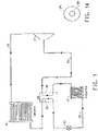
- Such a system generally includes an evaporator, a compressor, a condenser and an expansion device, and is known in the art. Reference will be made to Fig. 1 in describing this method.
- liquid working fluid from a condenser 41 flows through a line to an intermediate heat exchanger, or simply IHX.
- the intermediate heat exchanger includes a first tube 30, which contains a relatively hot liquid working fluid, and a second tube 50, which contains a relatively colder gaseous working fluid.
- the first tube of the IHX is connected to the outlet line of the condenser.
- the liquid working fluid then flows through an expansion device 52 and through a line 62 to an evaporator 42, which is located in the vicinity of a body to cooled. In the evaporator, the working fluid is evaporated, which converts it into a gaseous working fluid, and the vaporization of the working fluid provides cooling.
- the expansion device 52 may be an expansion valve, a capillary tube, an orifice tube or any other device where the working fluid may undergo an abrupt reduction in pressure.
- the evaporator has an outlet, through which the cold gaseous working fluid flows to the second tube 50 of the IHX, wherein the cold gaseous working fluid comes in thermal contact with the hot liquid working fluid in the first tube 30 of the IHX, and thus the cold gaseous working fluid is warmed somewhat.
- the gaseous working fluid flows from the second tube of the IHX through a line 63 to the inlet of a compressor 12.
- the gas is compressed in the compressor, and the compressed gaseous working fluid is discharged from the compressor and flows to the condenser 41 through a line 61 wherein the working fluid is condensed, thus giving off heat, and the cycle then repeats.
- the first tube containing the relatively hotter liquid working fluid and the second tube containing the relatively colder gaseous working fluid are in thermal contact, thus allowing transfer of heat from the hot liquid to the cold gas.
- the means by which the two tubes are in thermal contact may vary.
- the first tube has a larger diameter than the second tube, and the second tube is disposed concentrically in the first tube, and a hot liquid in the first tube surrounds a cold gas in the second tube. This embodiment is shown in FIG. 1A , where the first tube (30a) surrounds the second tube (50a).
- the working fluid in the second tube of the internal heat exchanger may flow in a countercurrent direction to the direction of flow of the working fluid in the first tube, thereby cooling the working fluid in the first tube and heating the working fluid in the second tube.
- Cross-current/counter-current heat exchange is provided in the system of Fig. 1 by a dual-row condenser or a dual-row evaporator.
- Such condensers and evaporators are described in detail in U.S. Provisional Patent Application No. 60/875,982, filed December 19, 2006 (now International Application PCT/US07/25675, filed December 17, 2007 ), and may be designed particularly for working fluids that comprise non-azeotropic or near-azeotropic compositions. Therefore, in accordance with the present invention, there is provided a vapor compression heat transfer system which comprises either a dual-row condenser, or a dual-row evaporator, or both. Such a system is the same as that described above with respect to FIG. 1 , except for the description of the dual-row condenser or the dual-row evaporator.
- FIG. 2 A dual-row condenser is shown at 41 in FIG. 2 .
- a hot working fluid enters the condenser through a first, or back, row 14, passes through the first row, and exits the condenser through a second, or front, row 13.
- the first row is connected to an inlet, or collector, 6, so that the working fluid enters first row 14 via collector, 6.
- the first row comprises a first inlet manifold and a plurality of channels, or passes, one of which is shown at 2 in Fig. 2 .
- the working fluid enters the inlet and flows inside first pass 2 of the first row.
- the channels allow the working fluid at a first temperature to flow into the manifold and then through the channels in at least one direction and collect in a second outlet manifold, which is shown at 15 in Fig. 2 .
- the working fluid In the first, or back, row the working fluid is cooled in a counter current manner by air, which has been heated by the second, or front row 13 of this dual-row condenser.
- the working fluid flows from first pass 2 of the first row 14, to a second row, 13 which is connected to the first row.
- the second row comprises a plurality of channels for conducting the working fluid at a second temperature less than the working in the first row.
- the working fluid flows from first pass 2 of the first row to a pass 3 of the second by a conduit, or connection 7 and by a conduit 16.
- the working fluid then flows from pass 3 to a pass 4 in second row 13 through a conduit, or connection 8, which connects the first and second rows.
- the working fluid then flows from pass 4 to a pass 5 through a conduit, or connection 9.
- the sub-cooled working fluid exits the condenser through outlet manifold 15 by a connection, or outlet, 10.
- Air is circulated in a counter-current manner relative to the working fluid flow, as indicated by the arrow having points 11 and 12 of FIG. 2 .
- the design shown in FIG. 2 is generic and can be used for any air-to-refrigerant condenser in stationary applications as well as in mobile applications.
- FIG. 3 A dual-row evaporator is shown at 42 in FIG. 3 .
- the dual-row evaporator includes an inlet, a first, or front, row 17 connected to the inlet, a second second, or back row 18, connected to the first row, and an outlet connected to the back row.
- the working fluid enters the evaporator 19 at the lowest temperature through an inlet, or collector, 24 as shown in FIG. 3 .
- the working fluid flows downwards through a tank 20 to a tank 21 through a collector 25, then from tank 21 to a tank 22 in the back row through a collector 26.
- the working fluid then flows from tank 22 to a tank 23 through a collector 27, and finally exits the evaporator through an outlet, or collector, 28.
- Air is circulated in a cross-countercurrent arrangement as indicated by the arrow having points 29 and 30, of FIG. 3 .
- the connecting lines between the components of the vapor compression heat transfer system, through which the working fluid may flow may be constructed of any typical conduit material known for such purpose.
- metal piping or metal tubing such as aluminum or copper or copper alloy tubing
- hoses constructed of various materials, such as polymers or elastomers, or combinations of such materials with reinforcing materials such as metal mesh etc, may be used in the system.
- compressors may be used in the vapor compression heat transfer system of the embodiments of the present invention, including reciprocating, rotary, jet, centrifugal, scroll, screw or axial-flow, depending on the mechanical means to compress the fluid, or as positive-displacement (e.g., reciprocating, scroll or screw) or dynamic (e.g., centrifugal or jet).
- positive-displacement e.g., reciprocating, scroll or screw
- dynamic e.g., centrifugal or jet
- the closed loop vapor compression heat transfer system as described herein may be used in stationary refrigeration, air-conditioning, and heat pumps or mobile air-conditioning and refrigeration systems.
- Stationary air-conditioning and heat pump applications include window, ductless, ducted, packaged terminal, chillers and light commercial and commercial air-conditioning systems, including packaged rooftop.
- Refrigeration applications include domestic or home refrigerators and freezers, ice machines, self-contained coolers and freezers, walk-in coolers and freezers and supermarket systems, and transport refrigeration systems.
- Mobile refrigeration or mobile air-conditioning systems refer to any refrigeration or air-conditioning system incorporated into a transportation unit for the road, rail, sea or air.
- apparatus which are meant to provide refrigeration or air-conditioning for a system independent of any moving carrier, known as “intermodal" systems, are included in the present invention.
- intermodal systems include “containers” (combined sea/land transport) as well as “swap bodies” (combined road and rail transport).
- the present invention is particularly useful for road transport refrigerating or air-conditioning apparatus, such as automobile air-conditioning apparatus or refrigerated road transport equipment.
- the working fluid utilized in the vapor compression heat transfer system comprises HFC-1234yf.
- the working fluid may further comprise at least one compound selected from hydrofluorocarbons, fluoroethers, hydrocarbons, dimethyl ether (DME), carbon dioxide (CO 2 ), ammonia (NH 3 ), and iodotrifluoromethane (CF 3 I).
- DME dimethyl ether
- CO 2 carbon dioxide
- NH 3 ammonia
- CF 3 I iodotrifluoromethane
- the working fluid may further comprise hydrofluorocarbons comprising at least one saturated compound containing carbon, hydrogen, and fluorine.
- hydrofluorocarbons comprising at least one saturated compound containing carbon, hydrogen, and fluorine.
- hydrofluorocarbons having 1 to 7 carbon atoms and having a normal boiling point of from about -90°C to about 80°C.
- Hydrofluorocarbons are commercial products available from a number of sources or may be prepared by methods known in the art.
- hydrofluorocarbon compounds include but are not limited to fluoromethane (CH 3 F, HFC-41), difluoromethane (CH 2 F 2 , HFC-32), trifluoromethane (CHF 3 , HFC-23), pentafluoroethane (CF 3 CHF 2 , HFC-125), 1,1,2,2-tetrafluoroethane (CHF 2 CHF 2 , HFC-134), 1,1,1,2-tetrafluoroethane (CF 3 CH 2 F, HFC-134a), 1,1,1-trifluoroethane (CF 3 CH 3 , HFC-143a), 1,1-difluoroethane (CHF 2 CH 3 , HFC-152a), fluoroethane (CH 3 CH 2 F, HFC-161), 1,1,1,2,2,3,3-heptafluoropropane (CF 3 CF 2 CHF 2 , HFC-227ca), 1,1,1,2,3,3,3-heptafluoropropan
- working fluids may further comprise fluoroethers comprising at least one compound having carbon, fluorine, oxygen and optionally hydrogen, chlorine, bromine or iodine.
- fluoroethers are commercially available or may be produced by methods known in the art.
- fluoroethers include but are not limited to nonafluoromethoxybutane (C 4 F 9 OCH 3 , any or all possible isomers or mixtures thereof); nonafluoroethoxybutane (C 4 F 9 OC 2 H 5 , any or all possible isomers or mixtures thereof); 2-difluoromethoxy-1,1,1,2-tetrafluoroethane (HFOC-236eaE ⁇ , or CHF 2 OCHFCF 3 ); 1,1-difluoro-2-methoxyethane (HFOC-272fbE ⁇ ,CH 3 OCH 2 CHF 2 ); 1,1,1,3,3,3-hexafluoro-2-(fluoromethoxy)propane (HFOC-347mmzE ⁇ , or CH 2 FOCH(CF 3 ) 2 ); 1,1,1,3,3,3-hexafluoro-2-methoxypropane (HFOC-356mmzE ⁇ , or CH 3 OCH(CH 3 ) 2 ); 1,1,1,2,2-
- working fluids may further comprise hydrocarbons comprising compounds having only carbon and hydrogen.
- hydrocarbons comprising compounds having only carbon and hydrogen.
- Hydrocarbons are commercially available through numerous chemical suppliers. Representative hydrocarbons include but are not limited to propane, n-butane, isobutane, cyclobutane, n-pentane, 2-methylbutane, 2,2-dimethylpropane, cyclopentane, n-hexane, 2-methylpentane, 2,2-dimethylbutane, 2,3-dimethylbutane, 3-methylpentane, cyclohexane, n-heptane, and cycloheptane.
- the working fluid may comprise hydrocarbons containing heteroatoms, such as dimethylether (DME, CH 3 OCH 3 ).
- DME dimethylether
- CH 3 OCH 3 dimethylether
- working fluids may further comprise carbon dioxide (CO 2 ), which is commercially available from various sources or may be prepared by methods known in the art.
- CO 2 carbon dioxide
- working fluids may further comprise ammonia (NH 3 ), which is commercially available from various sources or may be prepared by methods known in the art.
- NH 3 ammonia
- the working fluid further comprises at least one compound selected from hydrofluorocarbons, fluoroethers, hydrocarbons, dimethyl ether (DME), carbon dioxide (CO 2 ), ammonia (NH 3 ), and iodotrifluoromethane (CF 3 I).
- the working fluid further comprises at least one compound from the group consisting of HFC-134a, HFC-32, HFC-125, HFC-152a, and CF 3 I.
- the working fluid was a blend of 95% by weight HFC-1225ye and 5% by weight of HFC-32.
- Each system had a condenser, evaporator, compressor and a thermal expansion device.
- the ambient air temperature was 30 °C at the evaporator and the condenser inlets. Tests were performed for 2 compressor speeds, 1000 and 2000 rpm, and for 3 vehicle speeds: 25, 30, and 36 km/h.
- the volumetric flow rate of air on the evaporator was 380 m 3 /h.
- the cooling capacity for the system with an IHX shows an increase of 4 to 7% as compared to the system with no IHX.
- the COP also showed an increase of 2.5 to 4% for the system with the IHX as compared to a system with no IHX.
- Cooling performance is calculated for HFC-134a and HFC-1234yf both with and without an IHX.
- the conditions used are as follows: Condenser temperature 55 ° C Evaporator temperature 5 ° C Superheat (absolute) 15 ° C The data illustrating relative performance is shown in TABLE 5.
- the subcooling difference arises from the differences in molecular weight, liquid density and liquid heat capacity for HFC-1234yf as compared to HFC-134a. Based on these parameters it was estimated that there would be a difference in subcoolingachieved with the different compounds. When the HFC-134a subcool was set to 5 ° C, the corresponding subcooling for HFC-1234yf was calculated to be 5.8 ° C.
Landscapes
- Engineering & Computer Science (AREA)
- Physics & Mathematics (AREA)
- Mechanical Engineering (AREA)
- Thermal Sciences (AREA)
- General Engineering & Computer Science (AREA)
- Organic Low-Molecular-Weight Compounds And Preparation Thereof (AREA)
- Heat-Exchange Devices With Radiators And Conduit Assemblies (AREA)
- Engine Equipment That Uses Special Cycles (AREA)
- Vaporization, Distillation, Condensation, Sublimation, And Cold Traps (AREA)
- Secondary Cells (AREA)
Claims (5)
- Verfahren zum Austauschen von Wärme in einer Dampfkompressionswärmeübertragungsanlage, die ein durch dieselbe durchlaufendes Arbeitsfluid aufweist, die folgenden Schritte umfassend:(a) das Umwälzen eines Arbeitsfluids, umfassend ein Fluorolefin, zu einem Einlass eines ersten Rohres eines internen Wärmetauschers (30), durch den internen Wärmetauscher und zu einem Auslass desselben;(b) das Umwälzen des Arbeitsfluids von dem Auslass des ersten Rohres des internen Wärmetauschers zu einem Einlass eines Verdampfers (42), durch den Verdampfer, um das Arbeitsfluid zu verdampfen, um es dadurch in ein gasförmiges Arbeitsfluid umzuwandeln, und durch einen Auslass des Verdampfers;(c) das Umwälzen des Arbeitsfluids von dem Auslass des Verdampfers zu einem Einlass eines zweiten Rohres des internen Wärmetauschers (50), um Wärme von dem flüssigen Arbeitsfluid aus dem Kondensator (41) zu dem gasförmigen Arbeitsfluid von dem Verdampfer zu übertragen, durch den internen Wärmetauscher und zu einem Auslass des zweiten Rohres;(d) das Umwälzen des Arbeitsfluids von dem Auslass des zweiten Rohres des internen Wärmetauschers zu einem Einlass eines Verdichters (12), durch den Verdichter, um das gasförmige Arbeitsfluid zu verdichten, und zu einem Auslass des Verdichters;(e) das Umwälzen des Arbeitsfluids von dem Auslass des Verdichters zu einem Einlass eines Kondensators (41) und durch den Kondensator, um das verdichtete gasförmige Arbeitsfluid zu einer Flüssigkeit zu kondensieren, und zu einem Auslass des Kondensators;(f) das Umwälzen des Arbeitsfluids von dem Auslass des Kondensators zu einem Einlass des ersten Rohres des internen Wärmetauschers (30), um Wärme von der Flüssigkeit aus dem Kondensator zu dem Gas aus dem Verdampfer zu übertragen, und zu einem Auslass des ersten Rohres; und(g) das Umwälzen des Arbeitsfluids von dem Auslass des ersten Rohres des internen Wärmetauschers zurück zu dem Verdampfer (42);dadurch gekennzeichnet, dass das Arbeitsfluid HFC 1234yf umfasst,und wobei der Kondensierungsschritt Folgendes umfasst:(i) das Umwälzen des Arbeitsfluids zu einer hinteren Reihe (14) eines zweireihigen Kondensators (41), wobei die hintere Reihe das Arbeitsfluid bei einer ersten Temperatur aufnimmt, und(ii) das Umwälzen des Arbeitsfluids zu einer vorderen Reihe (13) des zweireihigen Kondensators, wobei die vordere Reihe das Arbeitsfluid bei einer zweiten Temperatur aufnimmt, wobei die zweite Temperatur geringer ist als die erste Temperatur, so dass Luft, die sich über die vordere Reihe und die hintere Reihe bewegt, vorgewärmt wird, wodurch die Temperatur der Luft größer ist, wenn sie die hintere Reihe erreicht, als wenn sie die vordere Reihe erreicht;
und/oderwobei der Verdampfungsschritt Folgendes umfasst:
(i) das Hindurchführen des Arbeitsfluids durch einen Einlass eines zweireihigen Kondensators (42), der eine erste Reihe und eine zweite Reihe aufweist, (ii) das Umwälzen des Arbeitsfluids in der ersten Reihe (17) in einer Richtung, senkrecht zu dem Fluidstrom durch den Einlass des Verdampfers, und (iii) das Umwälzen des Arbeitsfluids in der zweiten Reihe (18) in einer Richtung, im Allgemeinen entgegen der Richtung des Stroms des Arbeitsfluids durch den Einlass. - Verfahren nach Anspruch 1, wobei das Arbeitsfluid in dem zweiten Rohr des internen Wärmetauschers (50) in einer gegenläufigen Richtung zu der Strömungsrichtung des Arbeitsfluids in dem ersten Rohr des internen Wärmetauschers (30) strömt, wodurch das Arbeitsfluid in dem ersten Rohr gekühlt und das Arbeitsfluid in dem zweiten Rohr erhitzt wird.
- Verfahren nach Anspruch 1, wobei das erste Rohr des internen Wärmetauschers (30) einen größeren Durchmesser hat als das zweite Rohr des internen Wärmetauschers (50) und das zweite Rohr konzentrisch in dem ersten Rohr angeordnet ist und eine heiße Flüssigkeit in dem ersten Rohr ein kühles Gas in dem zweiten Rohr umgibt.
- Verfahren nach Anspruch 1, wobei das Arbeitsfluid ferner mindestens eine Verbindung, die ausgewählt ist aus Fluorkohlenwasserstoffen, Fluorethern, Kohlenwasserstoffen, Dimethylether (DME), Kohlendioxid (CO2), Ammoniak (NH3) und Iodotrifluormethan (CF3I), umfasst.
- Wärmeübertragungsanlage umfassend ein Arbeitsfluid, einen internen Wärmetauscher, einen Verdampfer, einen Verdichter und einen Kondensator, wobei:der interne Wärmetauscher ein erstes Rohr (30) mit einem Einlass und einem Auslass und ein zweites Rohr (50) mit einem Einlass und einem Auslass aufweist;der Verdampfer (42) einen Einlass und einen Auslass aufweist, wobei der Einlass des Verdampfers mit dem Auslass des ersten Rohrs des internen Wärmetauschers verbunden ist und der Auslass des Verdampfers mit dem Einlass des zweiten Rohrs des internen Wärmetauschers verbunden ist;der Verdichter (12) einen Einlass und einen Auslass aufweist, wobei der Einlass des Verdichters mit dem Auslass des zweiten Rohrs des internen Wärmetauschers verbunden ist und der Auslass des Verdichters mit dem Kondensator verbunden ist;der Kondensator (41) einen Einlass und einen Auslass aufweist, wobei der Einlass des Kondensators mit dem Auslass des Verdichters verbunden ist und der Auslass des Kondensators mit dem Einlass des ersten Rohrs des internen Wärmetauschers verbunden ist;dadurch gekennzeichnet, dass das Arbeitsfluid HFC-1234yf umfasst und wobeider Kondensator ein zweireihiger Kondensator ist, der Folgendes aufweist: (i) einen Einlass, (ii) eine erste Reihe (14), die mit dem Einlass verbunden ist, wobei die erste Reihe einen ersten Einlassverteiler und eine Vielzahl von Kanälen umfasst, um zu ermöglichen, dass ein Arbeitsfluid bei einer ersten Temperatur in den Verteiler und dann durch die Kanäle in mindestens eine Richtung strömt und sich in einem zweiten Auslassverteiler sammelt, (iii) eine zweite Reihe (13), die mit der ersten Reihe verbunden ist, wobei die zweite Reihe eine Vielzahl von Kanälen umfasst, um ein Arbeitsfluid mit einer zweiten Temperatur, die niedriger ist als die des Arbeitsfluids in der ersten Reihe, zu leiten, und (iv) eine Leitung, die die erste Reihe mit der zweiten Reihe verbindet;und/oder der Verdampfer ein zweireihiger Verdampfer zum Verdampfen eines Arbeitsfluids ist, wobei der Verdampfer Folgendes aufweist: (i) einen Einlass, (ii) eine vordere Reihe (17), die mit dem Einlass verbunden ist; (iii) eine hintere Reihe (18), die mit der vorderen Reihe verbunden ist, und (iv) einen Auslass, der mit der hinteren Reihe verbunden ist.
Priority Applications (2)
| Application Number | Priority Date | Filing Date | Title |
|---|---|---|---|
| EP24158471.3A EP4349694A3 (de) | 2007-01-31 | 2008-05-09 | Dampfkompressionswärmeübertragungssystem |
| EP22209806.3A EP4160127B1 (de) | 2007-01-31 | 2008-05-09 | Dampfkompressionswärmeübertragungssystem |
Applications Claiming Priority (5)
| Application Number | Priority Date | Filing Date | Title |
|---|---|---|---|
| US92882607P | 2007-05-11 | 2007-05-11 | |
| US98856207P | 2007-11-16 | 2007-11-16 | |
| PCT/US2007/025675 WO2008085314A2 (en) | 2006-12-19 | 2007-12-17 | Dual row heat exchanger and automobile bumper incorporating the same |
| PCT/US2008/006043 WO2008140809A2 (en) | 2007-05-11 | 2008-05-09 | Method for exchanging heat in a vapor compression heat transfer system and a vapor compression heat transfer system comprising an intermediate heat exchanger with a dual-row evaporator or condenser |
| EP08767666.4A EP2145150B8 (de) | 2007-05-11 | 2008-05-09 | Verfahren zur wärmetauschung in einem dampfkompressions-wärmeübertragungssystem und dampfkompressions-wärmeübertragungssystem mit einem zwischenwärmetauscher mit einem zweireihigen verdampfer oder kondensator |
Related Parent Applications (2)
| Application Number | Title | Priority Date | Filing Date |
|---|---|---|---|
| EP08767666.4A Division EP2145150B8 (de) | 2007-01-31 | 2008-05-09 | Verfahren zur wärmetauschung in einem dampfkompressions-wärmeübertragungssystem und dampfkompressions-wärmeübertragungssystem mit einem zwischenwärmetauscher mit einem zweireihigen verdampfer oder kondensator |
| EP08767666.4A Division-Into EP2145150B8 (de) | 2007-01-31 | 2008-05-09 | Verfahren zur wärmetauschung in einem dampfkompressions-wärmeübertragungssystem und dampfkompressions-wärmeübertragungssystem mit einem zwischenwärmetauscher mit einem zweireihigen verdampfer oder kondensator |
Related Child Applications (2)
| Application Number | Title | Priority Date | Filing Date |
|---|---|---|---|
| EP24158471.3A Division EP4349694A3 (de) | 2007-01-31 | 2008-05-09 | Dampfkompressionswärmeübertragungssystem |
| EP22209806.3A Division EP4160127B1 (de) | 2007-01-31 | 2008-05-09 | Dampfkompressionswärmeübertragungssystem |
Publications (2)
| Publication Number | Publication Date |
|---|---|
| EP3091320A1 EP3091320A1 (de) | 2016-11-09 |
| EP3091320B1 true EP3091320B1 (de) | 2022-11-30 |
Family
ID=39870623
Family Applications (4)
| Application Number | Title | Priority Date | Filing Date |
|---|---|---|---|
| EP16164723.5A Active EP3091320B1 (de) | 2007-01-31 | 2008-05-09 | Dampfkompressionswärmeübertragungssystem |
| EP22209806.3A Active EP4160127B1 (de) | 2007-01-31 | 2008-05-09 | Dampfkompressionswärmeübertragungssystem |
| EP24158471.3A Pending EP4349694A3 (de) | 2007-01-31 | 2008-05-09 | Dampfkompressionswärmeübertragungssystem |
| EP08767666.4A Revoked EP2145150B8 (de) | 2007-01-31 | 2008-05-09 | Verfahren zur wärmetauschung in einem dampfkompressions-wärmeübertragungssystem und dampfkompressions-wärmeübertragungssystem mit einem zwischenwärmetauscher mit einem zweireihigen verdampfer oder kondensator |
Family Applications After (3)
| Application Number | Title | Priority Date | Filing Date |
|---|---|---|---|
| EP22209806.3A Active EP4160127B1 (de) | 2007-01-31 | 2008-05-09 | Dampfkompressionswärmeübertragungssystem |
| EP24158471.3A Pending EP4349694A3 (de) | 2007-01-31 | 2008-05-09 | Dampfkompressionswärmeübertragungssystem |
| EP08767666.4A Revoked EP2145150B8 (de) | 2007-01-31 | 2008-05-09 | Verfahren zur wärmetauschung in einem dampfkompressions-wärmeübertragungssystem und dampfkompressions-wärmeübertragungssystem mit einem zwischenwärmetauscher mit einem zweireihigen verdampfer oder kondensator |
Country Status (11)
| Country | Link |
|---|---|
| US (6) | US20090120619A1 (de) |
| EP (4) | EP3091320B1 (de) |
| JP (1) | JP2010526982A (de) |
| KR (1) | KR101513319B1 (de) |
| CN (2) | CN101680691A (de) |
| AR (1) | AR066522A1 (de) |
| BR (1) | BRPI0810282A2 (de) |
| CA (3) | CA3002834C (de) |
| ES (3) | ES2575130T3 (de) |
| MX (1) | MX345550B (de) |
| WO (1) | WO2008140809A2 (de) |
Families Citing this family (67)
| Publication number | Priority date | Publication date | Assignee | Title |
|---|---|---|---|---|
| MY151990A (en) * | 2005-11-01 | 2014-07-31 | Du Pont | Solvent compositions comprising unsaturated fluorinated hydrocarbons |
| DE102006004870A1 (de) * | 2006-02-02 | 2007-08-16 | Siltronic Ag | Halbleiterschichtstruktur und Verfahren zur Herstellung einer Halbleiterschichtstruktur |
| MY160614A (en) * | 2006-02-28 | 2017-03-15 | Du Pont | Azeotropic compositions comprising fluorinated compounds for cleaning applications |
| US8974688B2 (en) * | 2009-07-29 | 2015-03-10 | Honeywell International Inc. | Compositions and methods for refrigeration |
| WO2008140809A2 (en) | 2007-05-11 | 2008-11-20 | E. I. Du Pont De Nemours And Company | Method for exchanging heat in a vapor compression heat transfer system and a vapor compression heat transfer system comprising an intermediate heat exchanger with a dual-row evaporator or condenser |
| US7641808B2 (en) | 2007-08-23 | 2010-01-05 | E.I. Du Pont De Nemours And Company | Azeotropic compositions comprising fluorinated olefins for cleaning applications |
| GB201002625D0 (en) * | 2010-02-16 | 2010-03-31 | Ineos Fluor Holdings Ltd | Heat transfer compositions |
| US8512591B2 (en) | 2007-10-12 | 2013-08-20 | Mexichem Amanco Holding S.A. De C.V. | Heat transfer compositions |
| US8628681B2 (en) | 2007-10-12 | 2014-01-14 | Mexichem Amanco Holding S.A. De C.V. | Heat transfer compositions |
| US8333901B2 (en) | 2007-10-12 | 2012-12-18 | Mexichem Amanco Holding S.A. De C.V. | Heat transfer compositions |
| JP2009257652A (ja) | 2008-02-29 | 2009-11-05 | Daikin Ind Ltd | 冷凍装置 |
| FR2936806B1 (fr) | 2008-10-08 | 2012-08-31 | Arkema France | Fluide refrigerant |
| FR2942237B1 (fr) * | 2009-02-13 | 2013-01-04 | Arkema France | Procede de chauffage et/ou climatisation d'un vehicule |
| CN102341444A (zh) * | 2009-03-06 | 2012-02-01 | 苏威氟有限公司 | 不饱和氢氟烃的用途 |
| JP5386201B2 (ja) * | 2009-03-12 | 2014-01-15 | 三菱重工業株式会社 | ヒートポンプ装置 |
| JP2010255906A (ja) * | 2009-04-23 | 2010-11-11 | Sanden Corp | 冷凍サイクル |
| GB0915004D0 (en) * | 2009-08-28 | 2009-09-30 | Ineos Fluor Holdings Ltd | Heat transfer composition |
| US9074115B2 (en) * | 2009-08-28 | 2015-07-07 | Mexichem Amanco Holding S.A. De C.V. | Heat transfer compositions |
| FR2950065B1 (fr) | 2009-09-11 | 2012-02-03 | Arkema France | Fluide refrigerant binaire |
| FR2950070B1 (fr) | 2009-09-11 | 2011-10-28 | Arkema France | Compositions ternaires pour refrigeration haute capacite |
| FR2950066B1 (fr) | 2009-09-11 | 2011-10-28 | Arkema France | Refrigeration basse et moyenne temperature |
| FR2950068B1 (fr) | 2009-09-11 | 2012-05-18 | Arkema France | Procede de transfert de chaleur |
| FR2950069B1 (fr) | 2009-09-11 | 2011-11-25 | Arkema France | Utilisation de compositions ternaires |
| FR2950071B1 (fr) | 2009-09-11 | 2012-02-03 | Arkema France | Compositions ternaires pour refrigeration basse capacite |
| US10035938B2 (en) | 2009-09-11 | 2018-07-31 | Arkema France | Heat transfer fluid replacing R-134a |
| CN102695772B (zh) * | 2009-09-16 | 2015-09-16 | 纳幕尔杜邦公司 | 装有反式-1,1,1,4,4,4-六氟-2-丁烯的冷却器设备以及在其中制冷的方法 |
| AR078902A1 (es) * | 2009-11-03 | 2011-12-14 | Du Pont | Sistema de refrigeracion en cascada con refrigerante de fluoroolefina |
| JP5730900B2 (ja) | 2009-12-21 | 2015-06-10 | イー・アイ・デュポン・ドウ・ヌムール・アンド・カンパニーE.I.Du Pont De Nemours And Company | テトラフルオロプロペンおよびジフルオロメタンを含む組成物ならびにその使用 |
| GB201002619D0 (en) * | 2010-02-16 | 2010-03-31 | Ineos Fluor Holdings Ltd | Heat transfer compositions |
| GB201002622D0 (en) | 2010-02-16 | 2010-03-31 | Ineos Fluor Holdings Ltd | Heat transfer compositions |
| FR2957083B1 (fr) * | 2010-03-02 | 2015-12-11 | Arkema France | Fluide de transfert de chaleur pour compresseur centrifuge |
| EP2558544B2 (de) | 2010-04-16 | 2024-09-04 | The Chemours Company FC, LLC | Chillers enthaltend zusammensetzungen mit 2,3,3,3-tetrafluorpropen und 1,1,1,2-tetrafluorethan |
| FR2959999B1 (fr) | 2010-05-11 | 2012-07-20 | Arkema France | Fluides de transfert de chaleur et leur utilisation dans des echangeurs de chaleur a contre-courant |
| FR2959997B1 (fr) | 2010-05-11 | 2012-06-08 | Arkema France | Fluides de transfert de chaleur et leur utilisation dans des echangeurs de chaleur a contre-courant |
| PL2571956T3 (pl) | 2010-05-20 | 2016-06-30 | Mexichem Fluor Sa De Cv | Kompozycje do wymiany ciepła |
| BR112012029453A2 (pt) | 2010-05-20 | 2017-03-07 | Mexichem Amanco Holding Sa | "composições para transferencia de calor, formação de espuma e pulverizavel, dispositivos para transferencia de calor e para geração de energia mecanica, uso de uma composição, agente para expansão, espuma, e, métodos para esfriar um artigo, para aquecer um artigo, para extrair uma substancia de biomassa, para limpar um artigo, para extrair um material de uma solução aquosa, para extrair um material de uma matriz sólida particulada, para reformar um dispositivo para transferência de calor, para reduzir o impacto ambiental decorrente da operação de um produto, para preparar uma composição e para gerar crédito de emissão de gás de efeito estufa" |
| GB2481443B (en) * | 2010-06-25 | 2012-10-17 | Mexichem Amanco Holding Sa | Heat transfer compositions |
| FR2964977B1 (fr) | 2010-09-20 | 2013-11-01 | Arkema France | Composition a base de 3,3,3-tetrafluoropropene |
| WO2012053157A1 (ja) * | 2010-10-22 | 2012-04-26 | 株式会社ヴァレオジャパン | 冷凍サイクル及び過冷却部付き凝縮器 |
| US20120119136A1 (en) * | 2010-11-12 | 2012-05-17 | Honeywell International Inc. | Low gwp heat transfer compositions |
| FR2976289B1 (fr) * | 2011-06-07 | 2013-05-24 | Arkema France | Compositions binaires de 1,3,3,3-tetrafluoropropene et d'ammoniac |
| US20130104575A1 (en) * | 2011-11-02 | 2013-05-02 | E I Du Pont De Nemours And Company | Use of compositions comprising 1,1,1,2,3-pentafluoropropane and optionally z-1,1,1,4,4,4-hexafluoro-2-butene in high temperature heat pumps |
| US20130333402A1 (en) * | 2012-06-18 | 2013-12-19 | GM Global Technology Operations LLC | Climate control systems for motor vehicles and methods of operating the same |
| US20140116083A1 (en) * | 2012-10-29 | 2014-05-01 | Myungjin Chung | Refrigerator |
| EP2970735A4 (de) * | 2013-03-15 | 2016-11-23 | Honeywell Int Inc | Wärmeübertragungszusammensetzungen und -verfahren |
| JP6381890B2 (ja) * | 2013-10-25 | 2018-08-29 | 三菱重工サーマルシステムズ株式会社 | 冷媒循環装置、冷媒循環方法および異性化抑制方法 |
| CN105473955B (zh) | 2013-10-25 | 2017-12-08 | 三菱重工制冷空调系统株式会社 | 冷媒循环装置、冷媒循环方法以及酸抑制方法 |
| EP2910887B1 (de) | 2014-02-21 | 2019-06-26 | Rolls-Royce Corporation | Mikrokanalwärmetauscher für gasturbinenzwischenkühlung und kondensation sowie korrespondierende methode |
| US10330364B2 (en) | 2014-06-26 | 2019-06-25 | Hudson Technologies, Inc. | System and method for retrofitting a refrigeration system from HCFC to HFC refrigerant |
| WO2016069785A1 (en) * | 2014-10-28 | 2016-05-06 | President And Fellows Of Harvard College | High energy efficiency phase change device using convex surface features |
| CN105820799A (zh) * | 2015-01-05 | 2016-08-03 | 浙江省化工研究院有限公司 | 一种含HFO-1234ze(E)的环保型制冷组合物 |
| CN107072106A (zh) * | 2016-12-28 | 2017-08-18 | 浙江海洋大学 | 无人船电路系统防火降温装置及防火降温方法 |
| JP7205476B2 (ja) * | 2017-08-25 | 2023-01-17 | Agc株式会社 | 溶剤組成物、洗浄方法、塗膜付き基材の製造方法及び熱移動媒体 |
| WO2019056855A1 (zh) * | 2017-09-20 | 2019-03-28 | 杭州三花家电热管理系统有限公司 | 换热组件、换热系统及室内采暖系统 |
| CN111788277B (zh) * | 2017-11-30 | 2022-05-10 | 霍尼韦尔国际公司 | 热传递组合物、方法和系统 |
| JP6952797B2 (ja) * | 2017-12-25 | 2021-10-20 | 三菱電機株式会社 | 熱交換器および冷凍サイクル装置 |
| CN110343510B (zh) | 2018-04-02 | 2021-06-04 | 江西天宇化工有限公司 | 一种不可燃并具有低温室效应的混合制冷剂及其应用 |
| CN110343509B (zh) * | 2018-04-02 | 2021-09-14 | 江西天宇化工有限公司 | 一种不可燃且能降低温室效应的混合制冷剂及其应用 |
| PL3870667T3 (pl) | 2018-10-26 | 2024-05-06 | The Chemours Company Fc, Llc | Kompozycje zawierające difluorometan, tetrafluoropropen i dwutlenek węgla oraz ich zastosowania |
| CN109945292B (zh) * | 2019-03-18 | 2021-05-25 | 山东大学 | 带辅助压缩机的双热源两级压缩热泵热水系统及方法 |
| JP2022084964A (ja) * | 2019-04-03 | 2022-06-08 | ダイキン工業株式会社 | 冷媒サイクル装置 |
| ES2912000T3 (es) * | 2019-05-21 | 2022-05-24 | Carrier Corp | Aparato de refrigeración y uso del mismo |
| US11765859B2 (en) * | 2021-10-12 | 2023-09-19 | The Chemours Company Fc, Llc | Methods of immersion cooling with low-GWP fluids in immersion cooling systems |
| JP2024537453A (ja) * | 2021-10-21 | 2024-10-10 | ザ ケマーズ カンパニー エフシー リミテッド ライアビリティ カンパニー | 2,3,3,3-テトラフルオロプロペンを含む組成物 |
| WO2025136893A1 (en) * | 2023-12-18 | 2025-06-26 | The Chemours Company Fc, Llc | High temperature heat pump system and method of use |
| WO2025160058A1 (en) * | 2024-01-22 | 2025-07-31 | The Chemours Company Fc, Llc | Process for the production of fluorinated alkenes and intermediates |
| CN118391834A (zh) * | 2024-06-11 | 2024-07-26 | 江苏凯立达节能科技有限公司 | 一种新型结构的过冷装置 |
Citations (2)
| Publication number | Priority date | Publication date | Assignee | Title |
|---|---|---|---|---|
| US20040244411A1 (en) * | 2003-05-27 | 2004-12-09 | Nobuo Ichimura | Air-conditioner |
| US20070100175A1 (en) * | 2005-11-01 | 2007-05-03 | Miller Ralph N | Azeotrope compositions comprising 2,3,3,3-tetrafluoropropene and hydrogen fluoride and uses thereof |
Family Cites Families (61)
| Publication number | Priority date | Publication date | Assignee | Title |
|---|---|---|---|---|
| US1507560A (en) | 1921-10-05 | 1924-09-09 | Island | |
| GB230612A (en) | 1924-02-21 | 1925-03-19 | Thomas Edgar Wood | Improvements in and relating to heat transmission apparatus |
| US2120764A (en) * | 1936-09-25 | 1938-06-14 | York Ice Machinery Corp | Refrigeration |
| FR1346189A (fr) | 1963-02-01 | 1963-12-13 | Gevaert Photo Prod Nv | Fabrication industrielle de cétène |
| BE652968A (de) | 1963-09-13 | 1964-12-31 | ||
| GB1027195A (en) | 1963-11-07 | 1966-04-27 | Metallurg Engineers Ltd | Improvements in heat exchangers |
| US3877242A (en) * | 1973-10-11 | 1975-04-15 | Int Refrigeration Engineers | Harvest control unit for an ice-making machine |
| DE2535490C2 (de) | 1975-08-08 | 1982-09-16 | Linde Ag, 6200 Wiesbaden | Kälteaggregat |
| GB1595616A (en) * | 1977-01-21 | 1981-08-12 | Hitachi Ltd | Air conditioning system |
| JPS55133167U (de) * | 1979-03-13 | 1980-09-20 | ||
| US4316366A (en) * | 1980-04-21 | 1982-02-23 | Carrier Corporation | Method and apparatus for integrating components of a refrigeration system |
| JPS62255762A (ja) | 1986-04-30 | 1987-11-07 | 株式会社日立製作所 | 空気調和機 |
| FR2614686A1 (fr) | 1987-04-28 | 1988-11-04 | Puicervert Luc | Echangeur |
| JPH03279763A (ja) * | 1990-03-27 | 1991-12-10 | Showa Alum Corp | 複式熱交換器 |
| US5529116A (en) | 1989-08-23 | 1996-06-25 | Showa Aluminum Corporation | Duplex heat exchanger |
| JP3030036B2 (ja) | 1989-08-23 | 2000-04-10 | 昭和アルミニウム株式会社 | 複式熱交換器 |
| JPH05170135A (ja) * | 1991-12-18 | 1993-07-09 | Mazda Motor Corp | 自動車の前部車体構造 |
| ES2161862T3 (es) | 1993-12-14 | 2001-12-16 | Du Pont | Proceso para la produccion de butanos perhalofluorados. |
| DE69533120D1 (de) * | 1994-05-30 | 2004-07-15 | Mitsubishi Electric Corp | Kühlmittelumlaufsystem |
| JPH1019418A (ja) * | 1996-07-03 | 1998-01-23 | Toshiba Corp | 冷凍冷蔵庫 |
| JPH1199964A (ja) | 1997-09-29 | 1999-04-13 | Aisin Seiki Co Ltd | 車両フロントエンドモジュール構造 |
| DE19813673B4 (de) * | 1998-03-27 | 2004-01-29 | Daimlerchrysler Ag | Verfahren und Vorrichtung zum Heizen und Kühlen eines Nutzraumes eines Kraftfahrzeuges |
| US6327866B1 (en) | 1998-12-30 | 2001-12-11 | Praxair Technology, Inc. | Food freezing method using a multicomponent refrigerant |
| US6176102B1 (en) * | 1998-12-30 | 2001-01-23 | Praxair Technology, Inc. | Method for providing refrigeration |
| JP2001121941A (ja) | 1999-10-28 | 2001-05-08 | Denso Corp | 熱交換器の車両搭載構造 |
| JP2001263831A (ja) * | 2000-03-24 | 2001-09-26 | Mitsubishi Electric Corp | 冷凍サイクル装置 |
| KR100426640B1 (ko) | 2000-09-25 | 2004-04-08 | 주식회사 템피아 | 냉동사이클 |
| JP4068312B2 (ja) * | 2001-06-18 | 2008-03-26 | カルソニックカンセイ株式会社 | 炭酸ガス用放熱器 |
| JP2003021432A (ja) | 2001-07-09 | 2003-01-24 | Zexel Valeo Climate Control Corp | コンデンサ |
| US6748759B2 (en) * | 2001-08-02 | 2004-06-15 | Ho-Hsin Wu | High efficiency heat exchanger |
| JPWO2003040640A1 (ja) * | 2001-11-08 | 2005-03-03 | 株式会社ゼクセルヴァレオクライメートコントロール | 熱交換器及び熱交換器用チューブ |
| WO2003102486A1 (en) * | 2002-05-31 | 2003-12-11 | Zexel Valeo Climate Control Corporation | Heat exchanger |
| JP2004011959A (ja) * | 2002-06-04 | 2004-01-15 | Sanyo Electric Co Ltd | 超臨界冷媒サイクル装置 |
| US20040089839A1 (en) | 2002-10-25 | 2004-05-13 | Honeywell International, Inc. | Fluorinated alkene refrigerant compositions |
| SI3170880T1 (sl) | 2002-10-25 | 2020-07-31 | Honeywell International Inc. | Uporaba sestavkov, ki kot hladilni sestavek vsebujejo HFO-1234ZE ali HFO-1234YF |
| KR100496376B1 (ko) * | 2003-03-31 | 2005-06-22 | 한명범 | 냉동사이클용 에너지효율 개선장치 |
| JP4124136B2 (ja) | 2003-04-21 | 2008-07-23 | 株式会社デンソー | 冷媒蒸発器 |
| JP2005037054A (ja) * | 2003-07-15 | 2005-02-10 | Sanyo Electric Co Ltd | 冷媒サイクル装置用熱交換器 |
| US7592494B2 (en) * | 2003-07-25 | 2009-09-22 | Honeywell International Inc. | Process for the manufacture of 1,3,3,3-tetrafluoropropene |
| GB2405688A (en) * | 2003-09-05 | 2005-03-09 | Applied Design & Eng Ltd | Refrigerator |
| JP2005083741A (ja) * | 2003-09-05 | 2005-03-31 | Lg Electronics Inc | 熱交換器及び冷媒切り替え手段を有する空調装置 |
| US7276177B2 (en) * | 2004-01-14 | 2007-10-02 | E.I. Dupont De Nemours And Company | Hydrofluorocarbon refrigerant compositions and uses thereof |
| WO2005103190A1 (en) * | 2004-04-16 | 2005-11-03 | Honeywell International Inc. | Azeotrope-like compositions of tetrafluoropropene and trifluoroiodomethane |
| US7605117B2 (en) * | 2004-04-16 | 2009-10-20 | Honeywell International Inc. | Methods of replacing refrigerant |
| US7629306B2 (en) | 2004-04-29 | 2009-12-08 | Honeywell International Inc. | Compositions comprising tetrafluoropropene and carbon dioxide |
| US7028490B2 (en) * | 2004-05-28 | 2006-04-18 | Ut-Batelle, Llc | Water-heating dehumidifier |
| JP2006183889A (ja) * | 2004-12-27 | 2006-07-13 | Nissan Motor Light Truck Co Ltd | ヒートポンプ装置 |
| US20060243945A1 (en) * | 2005-03-04 | 2006-11-02 | Minor Barbara H | Compositions comprising a fluoroolefin |
| US7569170B2 (en) | 2005-03-04 | 2009-08-04 | E.I. Du Pont De Nemours And Company | Compositions comprising a fluoroolefin |
| US20060243944A1 (en) * | 2005-03-04 | 2006-11-02 | Minor Barbara H | Compositions comprising a fluoroolefin |
| GB0507953D0 (en) * | 2005-04-21 | 2005-05-25 | Thermal Energy Systems Ltd | Heat pump |
| CN1710356A (zh) * | 2005-06-21 | 2005-12-21 | 上海本家空调系统有限公司 | 热回收蓄能型水源热泵 |
| TWI708756B (zh) * | 2005-06-24 | 2020-11-01 | 美商哈尼威爾國際公司 | 含有經氟取代之烯烴之組合物 |
| JP2007032949A (ja) * | 2005-07-28 | 2007-02-08 | Showa Denko Kk | 熱交換器 |
| JP4661449B2 (ja) * | 2005-08-17 | 2011-03-30 | 株式会社デンソー | エジェクタ式冷凍サイクル |
| JP4840681B2 (ja) | 2005-09-16 | 2011-12-21 | 株式会社ヴァレオジャパン | 熱交換器 |
| US7708903B2 (en) | 2005-11-01 | 2010-05-04 | E.I. Du Pont De Nemours And Company | Compositions comprising fluoroolefins and uses thereof |
| US7617766B2 (en) | 2006-08-25 | 2009-11-17 | Sunbeam Products, Inc. | Baby food maker |
| RU2009111881A (ru) | 2006-09-01 | 2010-10-10 | Е.И.Дюпон де Немур энд Компани (US) | Способ для циркулирования выбранных жидких теплоносителей через замкнутый цикл |
| EP2097702A2 (de) | 2006-12-19 | 2009-09-09 | E. I. Du Pont de Nemours and Company | Zweireihiger wärmetauscher und autostossstange damit |
| WO2008140809A2 (en) | 2007-05-11 | 2008-11-20 | E. I. Du Pont De Nemours And Company | Method for exchanging heat in a vapor compression heat transfer system and a vapor compression heat transfer system comprising an intermediate heat exchanger with a dual-row evaporator or condenser |
-
2008
- 2008-05-09 WO PCT/US2008/006043 patent/WO2008140809A2/en not_active Ceased
- 2008-05-09 ES ES08767666.4T patent/ES2575130T3/es active Active
- 2008-05-09 KR KR1020097025754A patent/KR101513319B1/ko active Active
- 2008-05-09 CN CN200880015513A patent/CN101680691A/zh active Pending
- 2008-05-09 CA CA3002834A patent/CA3002834C/en active Active
- 2008-05-09 EP EP16164723.5A patent/EP3091320B1/de active Active
- 2008-05-09 CA CA2682312A patent/CA2682312C/en active Active
- 2008-05-09 EP EP22209806.3A patent/EP4160127B1/de active Active
- 2008-05-09 EP EP24158471.3A patent/EP4349694A3/de active Pending
- 2008-05-09 MX MX2009012100A patent/MX345550B/es active IP Right Grant
- 2008-05-09 CN CN201510800415.1A patent/CN105333653A/zh active Pending
- 2008-05-09 CA CA2944695A patent/CA2944695C/en active Active
- 2008-05-09 BR BRPI0810282A patent/BRPI0810282A2/pt not_active IP Right Cessation
- 2008-05-09 ES ES22209806T patent/ES2982776T3/es active Active
- 2008-05-09 JP JP2010507484A patent/JP2010526982A/ja active Pending
- 2008-05-09 EP EP08767666.4A patent/EP2145150B8/de not_active Revoked
- 2008-05-09 ES ES16164723T patent/ES2935119T3/es active Active
- 2008-05-09 AR ARP080101986A patent/AR066522A1/es not_active Application Discontinuation
- 2008-05-12 US US12/119,023 patent/US20090120619A1/en not_active Abandoned
-
2011
- 2011-08-11 US US13/207,557 patent/US20110290447A1/en not_active Abandoned
-
2018
- 2018-03-29 US US15/939,644 patent/US11624534B2/en active Active
-
2022
- 2022-12-19 US US18/084,201 patent/US11867436B2/en active Active
-
2023
- 2023-11-17 US US18/512,520 patent/US12287129B2/en active Active
-
2025
- 2025-03-27 US US19/091,951 patent/US20250224161A1/en active Pending
Patent Citations (2)
| Publication number | Priority date | Publication date | Assignee | Title |
|---|---|---|---|---|
| US20040244411A1 (en) * | 2003-05-27 | 2004-12-09 | Nobuo Ichimura | Air-conditioner |
| US20070100175A1 (en) * | 2005-11-01 | 2007-05-03 | Miller Ralph N | Azeotrope compositions comprising 2,3,3,3-tetrafluoropropene and hydrogen fluoride and uses thereof |
Also Published As
Similar Documents
| Publication | Publication Date | Title |
|---|---|---|
| EP3091320B1 (de) | Dampfkompressionswärmeübertragungssystem | |
| CN102686957B (zh) | 具有氟烯烃制冷剂的阶式制冷系统 | |
| CN101622509B (zh) | 汽车用空调系统 | |
| JP5423089B2 (ja) | 冷凍装置 | |
| CN102089400A (zh) | 包含离子液体和氟烯烃的组合物以及它们在吸收循环体系中的用途 | |
| JP6418284B1 (ja) | 冷媒を含有する組成物、その使用、それを用いた冷凍方法、及びそれを含む冷凍機 | |
| EP4467628A1 (de) | Kühlmittelzusammensetzung und wärmepumpe damit | |
| EP4509576A1 (de) | Gemischte kühlmittelzusammensetzung und wärmepumpe damit | |
| HK1150366A (en) | Method for exchanging heat in a vapor compression heat transfer system and a vapor compression heat transfer system comprising an intermediate heat exchanger with a dual-row evaporator or condenser | |
| KR20260045348A (ko) | 혼합 냉매 조성물 및 이를 포함하는 히트 펌프 | |
| CN118633008A (zh) | 形成制冷剂系统的方法 |
Legal Events
| Date | Code | Title | Description |
|---|---|---|---|
| PUAI | Public reference made under article 153(3) epc to a published international application that has entered the european phase |
Free format text: ORIGINAL CODE: 0009012 |
|
| AC | Divisional application: reference to earlier application |
Ref document number: 2145150 Country of ref document: EP Kind code of ref document: P |
|
| AK | Designated contracting states |
Kind code of ref document: A1 Designated state(s): AT BE BG CH CY CZ DE DK EE ES FI FR GB GR HR HU IE IS IT LI LT LU LV MC MT NL NO PL PT RO SE SI SK TR |
|
| STAA | Information on the status of an ep patent application or granted ep patent |
Free format text: STATUS: THE APPLICATION HAS BEEN PUBLISHED |
|
| STAA | Information on the status of an ep patent application or granted ep patent |
Free format text: STATUS: REQUEST FOR EXAMINATION WAS MADE |
|
| 17P | Request for examination filed |
Effective date: 20170731 |
|
| RBV | Designated contracting states (corrected) |
Designated state(s): AT BE BG CH CY CZ DE DK EE ES FI FR GB GR HR HU IE IS IT LI LT LU LV MC MT NL NO PL PT RO SE SI SK TR |
|
| STAA | Information on the status of an ep patent application or granted ep patent |
Free format text: STATUS: EXAMINATION IS IN PROGRESS |
|
| 17Q | First examination report despatched |
Effective date: 20190306 |
|
| RIC1 | Information provided on ipc code assigned before grant |
Ipc: F28D 21/00 20060101ALN20220425BHEP Ipc: F28D 1/04 20060101ALI20220425BHEP Ipc: F25B 40/00 20060101ALI20220425BHEP Ipc: B62D 25/00 20060101ALI20220425BHEP Ipc: F28D 1/053 20060101AFI20220425BHEP |
|
| RIC1 | Information provided on ipc code assigned before grant |
Ipc: F28D 21/00 20060101ALN20220511BHEP Ipc: F28D 1/04 20060101ALI20220511BHEP Ipc: F25B 40/00 20060101ALI20220511BHEP Ipc: B62D 25/00 20060101ALI20220511BHEP Ipc: F28D 1/053 20060101AFI20220511BHEP |
|
| GRAP | Despatch of communication of intention to grant a patent |
Free format text: ORIGINAL CODE: EPIDOSNIGR1 |
|
| STAA | Information on the status of an ep patent application or granted ep patent |
Free format text: STATUS: GRANT OF PATENT IS INTENDED |
|
| INTG | Intention to grant announced |
Effective date: 20220620 |
|
| GRAS | Grant fee paid |
Free format text: ORIGINAL CODE: EPIDOSNIGR3 |
|
| GRAA | (expected) grant |
Free format text: ORIGINAL CODE: 0009210 |
|
| STAA | Information on the status of an ep patent application or granted ep patent |
Free format text: STATUS: THE PATENT HAS BEEN GRANTED |
|
| AC | Divisional application: reference to earlier application |
Ref document number: 2145150 Country of ref document: EP Kind code of ref document: P |
|
| AK | Designated contracting states |
Kind code of ref document: B1 Designated state(s): AT BE BG CH CY CZ DE DK EE ES FI FR GB GR HR HU IE IS IT LI LT LU LV MC MT NL NO PL PT RO SE SI SK TR |
|
| REG | Reference to a national code |
Ref country code: CH Ref legal event code: EP Ref country code: GB Ref legal event code: FG4D |
|
| REG | Reference to a national code |
Ref country code: AT Ref legal event code: REF Ref document number: 1534969 Country of ref document: AT Kind code of ref document: T Effective date: 20221215 |
|
| REG | Reference to a national code |
Ref country code: IE Ref legal event code: FG4D |
|
| REG | Reference to a national code |
Ref country code: DE Ref legal event code: R096 Ref document number: 602008064671 Country of ref document: DE |
|
| REG | Reference to a national code |
Ref country code: ES Ref legal event code: FG2A Ref document number: 2935119 Country of ref document: ES Kind code of ref document: T3 Effective date: 20230301 |
|
| REG | Reference to a national code |
Ref country code: LT Ref legal event code: MG9D |
|
| REG | Reference to a national code |
Ref country code: NL Ref legal event code: MP Effective date: 20221130 |
|
| PG25 | Lapsed in a contracting state [announced via postgrant information from national office to epo] |
Ref country code: SE Free format text: LAPSE BECAUSE OF FAILURE TO SUBMIT A TRANSLATION OF THE DESCRIPTION OR TO PAY THE FEE WITHIN THE PRESCRIBED TIME-LIMIT Effective date: 20221130 Ref country code: PT Free format text: LAPSE BECAUSE OF FAILURE TO SUBMIT A TRANSLATION OF THE DESCRIPTION OR TO PAY THE FEE WITHIN THE PRESCRIBED TIME-LIMIT Effective date: 20230331 Ref country code: NO Free format text: LAPSE BECAUSE OF FAILURE TO SUBMIT A TRANSLATION OF THE DESCRIPTION OR TO PAY THE FEE WITHIN THE PRESCRIBED TIME-LIMIT Effective date: 20230228 Ref country code: LT Free format text: LAPSE BECAUSE OF FAILURE TO SUBMIT A TRANSLATION OF THE DESCRIPTION OR TO PAY THE FEE WITHIN THE PRESCRIBED TIME-LIMIT Effective date: 20221130 Ref country code: FI Free format text: LAPSE BECAUSE OF FAILURE TO SUBMIT A TRANSLATION OF THE DESCRIPTION OR TO PAY THE FEE WITHIN THE PRESCRIBED TIME-LIMIT Effective date: 20221130 |
|
| REG | Reference to a national code |
Ref country code: AT Ref legal event code: MK05 Ref document number: 1534969 Country of ref document: AT Kind code of ref document: T Effective date: 20221130 |
|
| PG25 | Lapsed in a contracting state [announced via postgrant information from national office to epo] |
Ref country code: PL Free format text: LAPSE BECAUSE OF FAILURE TO SUBMIT A TRANSLATION OF THE DESCRIPTION OR TO PAY THE FEE WITHIN THE PRESCRIBED TIME-LIMIT Effective date: 20221130 Ref country code: LV Free format text: LAPSE BECAUSE OF FAILURE TO SUBMIT A TRANSLATION OF THE DESCRIPTION OR TO PAY THE FEE WITHIN THE PRESCRIBED TIME-LIMIT Effective date: 20221130 Ref country code: IS Free format text: LAPSE BECAUSE OF FAILURE TO SUBMIT A TRANSLATION OF THE DESCRIPTION OR TO PAY THE FEE WITHIN THE PRESCRIBED TIME-LIMIT Effective date: 20230330 Ref country code: HR Free format text: LAPSE BECAUSE OF FAILURE TO SUBMIT A TRANSLATION OF THE DESCRIPTION OR TO PAY THE FEE WITHIN THE PRESCRIBED TIME-LIMIT Effective date: 20221130 Ref country code: GR Free format text: LAPSE BECAUSE OF FAILURE TO SUBMIT A TRANSLATION OF THE DESCRIPTION OR TO PAY THE FEE WITHIN THE PRESCRIBED TIME-LIMIT Effective date: 20230301 |
|
| P01 | Opt-out of the competence of the unified patent court (upc) registered |
Effective date: 20230516 |
|
| PG25 | Lapsed in a contracting state [announced via postgrant information from national office to epo] |
Ref country code: NL Free format text: LAPSE BECAUSE OF FAILURE TO SUBMIT A TRANSLATION OF THE DESCRIPTION OR TO PAY THE FEE WITHIN THE PRESCRIBED TIME-LIMIT Effective date: 20221130 |
|
| PG25 | Lapsed in a contracting state [announced via postgrant information from national office to epo] |
Ref country code: RO Free format text: LAPSE BECAUSE OF FAILURE TO SUBMIT A TRANSLATION OF THE DESCRIPTION OR TO PAY THE FEE WITHIN THE PRESCRIBED TIME-LIMIT Effective date: 20221130 Ref country code: EE Free format text: LAPSE BECAUSE OF FAILURE TO SUBMIT A TRANSLATION OF THE DESCRIPTION OR TO PAY THE FEE WITHIN THE PRESCRIBED TIME-LIMIT Effective date: 20221130 Ref country code: DK Free format text: LAPSE BECAUSE OF FAILURE TO SUBMIT A TRANSLATION OF THE DESCRIPTION OR TO PAY THE FEE WITHIN THE PRESCRIBED TIME-LIMIT Effective date: 20221130 Ref country code: CZ Free format text: LAPSE BECAUSE OF FAILURE TO SUBMIT A TRANSLATION OF THE DESCRIPTION OR TO PAY THE FEE WITHIN THE PRESCRIBED TIME-LIMIT Effective date: 20221130 Ref country code: AT Free format text: LAPSE BECAUSE OF FAILURE TO SUBMIT A TRANSLATION OF THE DESCRIPTION OR TO PAY THE FEE WITHIN THE PRESCRIBED TIME-LIMIT Effective date: 20221130 |
|
| PG25 | Lapsed in a contracting state [announced via postgrant information from national office to epo] |
Ref country code: SK Free format text: LAPSE BECAUSE OF FAILURE TO SUBMIT A TRANSLATION OF THE DESCRIPTION OR TO PAY THE FEE WITHIN THE PRESCRIBED TIME-LIMIT Effective date: 20221130 |
|
| REG | Reference to a national code |
Ref country code: DE Ref legal event code: R097 Ref document number: 602008064671 Country of ref document: DE |
|
| PLBE | No opposition filed within time limit |
Free format text: ORIGINAL CODE: 0009261 |
|
| STAA | Information on the status of an ep patent application or granted ep patent |
Free format text: STATUS: NO OPPOSITION FILED WITHIN TIME LIMIT |
|
| 26N | No opposition filed |
Effective date: 20230831 |
|
| PG25 | Lapsed in a contracting state [announced via postgrant information from national office to epo] |
Ref country code: SI Free format text: LAPSE BECAUSE OF FAILURE TO SUBMIT A TRANSLATION OF THE DESCRIPTION OR TO PAY THE FEE WITHIN THE PRESCRIBED TIME-LIMIT Effective date: 20221130 |
|
| REG | Reference to a national code |
Ref country code: CH Ref legal event code: PL |
|
| PG25 | Lapsed in a contracting state [announced via postgrant information from national office to epo] |
Ref country code: MC Free format text: LAPSE BECAUSE OF FAILURE TO SUBMIT A TRANSLATION OF THE DESCRIPTION OR TO PAY THE FEE WITHIN THE PRESCRIBED TIME-LIMIT Effective date: 20221130 |
|
| REG | Reference to a national code |
Ref country code: BE Ref legal event code: MM Effective date: 20230531 |
|
| PG25 | Lapsed in a contracting state [announced via postgrant information from national office to epo] |
Ref country code: MC Free format text: LAPSE BECAUSE OF FAILURE TO SUBMIT A TRANSLATION OF THE DESCRIPTION OR TO PAY THE FEE WITHIN THE PRESCRIBED TIME-LIMIT Effective date: 20221130 Ref country code: LU Free format text: LAPSE BECAUSE OF NON-PAYMENT OF DUE FEES Effective date: 20230509 Ref country code: LI Free format text: LAPSE BECAUSE OF NON-PAYMENT OF DUE FEES Effective date: 20230531 Ref country code: CH Free format text: LAPSE BECAUSE OF NON-PAYMENT OF DUE FEES Effective date: 20230531 |
|
| REG | Reference to a national code |
Ref country code: IE Ref legal event code: MM4A |
|
| PG25 | Lapsed in a contracting state [announced via postgrant information from national office to epo] |
Ref country code: IE Free format text: LAPSE BECAUSE OF NON-PAYMENT OF DUE FEES Effective date: 20230509 |
|
| PG25 | Lapsed in a contracting state [announced via postgrant information from national office to epo] |
Ref country code: IE Free format text: LAPSE BECAUSE OF NON-PAYMENT OF DUE FEES Effective date: 20230509 |
|
| PG25 | Lapsed in a contracting state [announced via postgrant information from national office to epo] |
Ref country code: BE Free format text: LAPSE BECAUSE OF NON-PAYMENT OF DUE FEES Effective date: 20230531 |
|
| PG25 | Lapsed in a contracting state [announced via postgrant information from national office to epo] |
Ref country code: BG Free format text: LAPSE BECAUSE OF FAILURE TO SUBMIT A TRANSLATION OF THE DESCRIPTION OR TO PAY THE FEE WITHIN THE PRESCRIBED TIME-LIMIT Effective date: 20221130 |
|
| PG25 | Lapsed in a contracting state [announced via postgrant information from national office to epo] |
Ref country code: BG Free format text: LAPSE BECAUSE OF FAILURE TO SUBMIT A TRANSLATION OF THE DESCRIPTION OR TO PAY THE FEE WITHIN THE PRESCRIBED TIME-LIMIT Effective date: 20221130 |
|
| PGFP | Annual fee paid to national office [announced via postgrant information from national office to epo] |
Ref country code: DE Payment date: 20250423 Year of fee payment: 18 |
|
| PGFP | Annual fee paid to national office [announced via postgrant information from national office to epo] |
Ref country code: ES Payment date: 20250602 Year of fee payment: 18 Ref country code: GB Payment date: 20250423 Year of fee payment: 18 |
|
| PGFP | Annual fee paid to national office [announced via postgrant information from national office to epo] |
Ref country code: IT Payment date: 20250423 Year of fee payment: 18 |
|
| PGFP | Annual fee paid to national office [announced via postgrant information from national office to epo] |
Ref country code: FR Payment date: 20250423 Year of fee payment: 18 |
|
| PG25 | Lapsed in a contracting state [announced via postgrant information from national office to epo] |
Ref country code: CY Free format text: LAPSE BECAUSE OF FAILURE TO SUBMIT A TRANSLATION OF THE DESCRIPTION OR TO PAY THE FEE WITHIN THE PRESCRIBED TIME-LIMIT; INVALID AB INITIO Effective date: 20080509 |
|
| PG25 | Lapsed in a contracting state [announced via postgrant information from national office to epo] |
Ref country code: HU Free format text: LAPSE BECAUSE OF FAILURE TO SUBMIT A TRANSLATION OF THE DESCRIPTION OR TO PAY THE FEE WITHIN THE PRESCRIBED TIME-LIMIT; INVALID AB INITIO Effective date: 20080509 |
|
| PG25 | Lapsed in a contracting state [announced via postgrant information from national office to epo] |
Ref country code: TR Free format text: LAPSE BECAUSE OF FAILURE TO SUBMIT A TRANSLATION OF THE DESCRIPTION OR TO PAY THE FEE WITHIN THE PRESCRIBED TIME-LIMIT Effective date: 20221130 |