EP3092974A1 - Dispositif d'hygiène personnel avec unité de mesure de force de traitement - Google Patents
Dispositif d'hygiène personnel avec unité de mesure de force de traitement Download PDFInfo
- Publication number
- EP3092974A1 EP3092974A1 EP15167364.7A EP15167364A EP3092974A1 EP 3092974 A1 EP3092974 A1 EP 3092974A1 EP 15167364 A EP15167364 A EP 15167364A EP 3092974 A1 EP3092974 A1 EP 3092974A1
- Authority
- EP
- European Patent Office
- Prior art keywords
- light
- treatment
- personal hygiene
- hygiene device
- force
- Prior art date
- Legal status (The legal status is an assumption and is not a legal conclusion. Google has not performed a legal analysis and makes no representation as to the accuracy of the status listed.)
- Granted
Links
Images


Classifications
-
- A—HUMAN NECESSITIES
- A46—BRUSHWARE
- A46B—BRUSHES
- A46B15/00—Other brushes; Brushes with additional arrangements
- A46B15/0002—Arrangements for enhancing monitoring or controlling the brushing process
- A46B15/0004—Arrangements for enhancing monitoring or controlling the brushing process with a controlling means
- A46B15/0012—Arrangements for enhancing monitoring or controlling the brushing process with a controlling means with a pressure controlling device
-
- A—HUMAN NECESSITIES
- A46—BRUSHWARE
- A46B—BRUSHES
- A46B15/00—Other brushes; Brushes with additional arrangements
- A46B15/0002—Arrangements for enhancing monitoring or controlling the brushing process
- A46B15/0004—Arrangements for enhancing monitoring or controlling the brushing process with a controlling means
- A46B15/0014—Arrangements for enhancing monitoring or controlling the brushing process with a controlling means with a controlling temperature device
-
- A—HUMAN NECESSITIES
- A46—BRUSHWARE
- A46B—BRUSHES
- A46B15/00—Other brushes; Brushes with additional arrangements
- A46B15/0002—Arrangements for enhancing monitoring or controlling the brushing process
- A46B15/0016—Arrangements for enhancing monitoring or controlling the brushing process with enhancing means
- A46B15/0034—Arrangements for enhancing monitoring or controlling the brushing process with enhancing means with a source of radiation, e.g. UV, IR, LASER, X-ray for irradiating the teeth and associated surfaces
-
- A—HUMAN NECESSITIES
- A46—BRUSHWARE
- A46B—BRUSHES
- A46B15/00—Other brushes; Brushes with additional arrangements
- A46B15/0002—Arrangements for enhancing monitoring or controlling the brushing process
- A46B15/0038—Arrangements for enhancing monitoring or controlling the brushing process with signalling means
- A46B15/004—Arrangements for enhancing monitoring or controlling the brushing process with signalling means with an acoustic signalling means, e.g. noise
-
- A—HUMAN NECESSITIES
- A46—BRUSHWARE
- A46B—BRUSHES
- A46B15/00—Other brushes; Brushes with additional arrangements
- A46B15/0002—Arrangements for enhancing monitoring or controlling the brushing process
- A46B15/0038—Arrangements for enhancing monitoring or controlling the brushing process with signalling means
- A46B15/0044—Arrangements for enhancing monitoring or controlling the brushing process with signalling means with light signalling means
-
- A—HUMAN NECESSITIES
- A46—BRUSHWARE
- A46B—BRUSHES
- A46B15/00—Other brushes; Brushes with additional arrangements
- A46B15/0002—Arrangements for enhancing monitoring or controlling the brushing process
- A46B15/0038—Arrangements for enhancing monitoring or controlling the brushing process with signalling means
- A46B15/0046—Arrangements for enhancing monitoring or controlling the brushing process with signalling means with vibrating signalling means
-
- A—HUMAN NECESSITIES
- A46—BRUSHWARE
- A46B—BRUSHES
- A46B5/00—Brush bodies; Handles integral with brushware
- A46B5/002—Brush bodies; Handles integral with brushware having articulations, joints or flexible portions
- A46B5/0025—Brushes with elastically deformable heads that change shape during use
-
- A—HUMAN NECESSITIES
- A46—BRUSHWARE
- A46B—BRUSHES
- A46B5/00—Brush bodies; Handles integral with brushware
- A46B5/002—Brush bodies; Handles integral with brushware having articulations, joints or flexible portions
- A46B5/0054—Brush bodies; Handles integral with brushware having articulations, joints or flexible portions designed to allow relative positioning of the head to body
- A46B5/0062—Brush bodies; Handles integral with brushware having articulations, joints or flexible portions designed to allow relative positioning of the head to body being flexible or resilient during use
- A46B5/007—Inserts made of different material, e.g. springs, plates
-
- A—HUMAN NECESSITIES
- A46—BRUSHWARE
- A46B—BRUSHES
- A46B9/00—Arrangements of the bristles in the brush body
- A46B9/02—Position or arrangement of bristles in relation to surface of the brush body, e.g. inclined, in rows, in groups
- A46B9/04—Arranged like in or for toothbrushes
-
- A—HUMAN NECESSITIES
- A61—MEDICAL OR VETERINARY SCIENCE; HYGIENE
- A61C—DENTISTRY; APPARATUS OR METHODS FOR ORAL OR DENTAL HYGIENE
- A61C17/00—Devices for cleaning, polishing, rinsing or drying teeth, teeth cavities or prostheses; Saliva removers; Dental appliances for receiving spittle
- A61C17/16—Power-driven cleaning or polishing devices
- A61C17/22—Power-driven cleaning or polishing devices with brushes, cushions, cups, or the like
- A61C17/221—Control arrangements therefor
Definitions
- the present invention is concerned with a personal hygiene device having a treatment force measurement unit, in particular wherein the treatment force measurement unit is arranged to measure the treatment force applied at a treatment head that is mounted for movement under application of a treatment force relative to a handle of the personal hygiene device.
- a toothbrush can be equipped with a treatment force measurement unit for determining when a treatment force with which a toothbrush head is pushed against the teeth reaches a predetermined treatment force threshold value.
- a treatment force measurement unit may comprise a strain gauge sensor. It is also known that reaching the pre-determined treatment force threshold value can be visually indicated. DE 34 146 23 C1 generally discusses such a toothbrush.
- a personal hygiene device in particular a toothbrush having a handle, a treatment head mounted for relative movement of at least a portion of the treatment head with respect to the handle against a restoring force when a treatment force is applied in at least one direction onto the treatment head, a treatment force measurement unit for determining the applied treatment force comprising a light emitting element, a light sensitive element, and a light changing element arranged at least partly in the light path between the light emitting element and the light sensitive element, wherein the light changing element and at least one of the light emitting element or light sensitive element are arranged to be moved relatively to each other when at least the portion of the treatment head is moved.
- an electric toothbrush as personal hygiene device.
- light shall mean any suitable electromagnetic radiation, in particular light in the wavelength range typically visible to the human eye (which in the present application shall mean the wavelength range between 400 nanometer (nm) and 700 nm), in the infrared wavelength range (which in the present application shall mean the wavelength range between 700 nm and 1 millimeter (mm)) or in the ultraviolet wavelength range (which in the present application shall mean the wavelength range between 10 nm and 400 nm).
- light that is essentially invisible for the human eye is used so that the user of the proposed personal hygiene device is not distracted or confused by visible light that may shine through the handle of the personal hygiene device.
- a “light emitting element” may be any suitable element such as a light emitting diode (LED), an organic LED (OLED), a laser or laser diode, or a regular lamp (arc lamp, gas discharge lamp etc.).
- LED light emitting diode
- OLED organic LED
- laser or laser diode or a regular lamp (arc lamp, gas discharge lamp etc.).
- an infrared LED may be used, e.g. an LED based on gallium arsenide that may have an emission wavelength of 840 nm, 850 nm, 875 nm, 880 nm, 885 nm, 890 nm, 940 nm, or 950 nm.
- LEDs based on gallium nitride may be used for emitting ultraviolet light, in particular in the near UV wavelength range of between 375 nm to 395 nm.
- UV LEDs down to a wavelength of 240 nm are commercially available and are considered as well. LEDs emitting light in the visible wavelength ranges (e.g. blue, red, or green LEDs) may be used as well a bicolor, tri-color, or RGB-LEDs.
- a "light sensitive element” may in particular be realized as a photodiode, in particular as silicon (Si) or germanium (Ge) based photodiode.
- Si-based photodiodes have high responsiveness in particular in the higher IR wavelength range (e.g. around 940 nm).
- Phototransistors, CCD- or CMOS-based light sensors, photoresistors, photocondutors etc. may also be used as light sensitive elements.
- any element that changes its response, in particular its electric characteristic, in dependency on changing light intensity may be usable as light sensitive element.
- a light sensitive element may have a finite light sensitive area (e.g. the light sensitive area may be 1 mm 2 , even though this value shall not be construed as limiting).
- a “light changing element” is an element that interacts with the light that is emitted by the light emitting element and progresses along a light path to eventually impinge onto the light sensitive element of the light sensitive element.
- “Interaction” shall here include absorption as well as reflection and scattering.
- a direct light path exists between light emitting element and light sensitive element and a relative movement of the light changing element shall lead to a change in the amount of absorbed light so that an output signal of the light sensitive element changes accordingly.
- the light changing element may in particular be designed such that a relative movement of the light changing element out of a rest position up to a maximally deflected position leads in a monotone manner (i.e.
- each output signal can be related (in particular via calibration) to an applied treatment force acting on the treatment head.
- the relationship between the output signal of the light sensitive element and the applied treatment force is calibrated, e.g. at the plant of the manufacturer, i.e. the treatment force measurement unit is than arranged for calibration.
- an indirect light path exists between light emitting element and light sensitive element, i.e. the light that impinges on the light sensitive element has previously been reflected by the light changing element.
- Relative movement of the light changing element shall lead to a change in the amount of light impinging onto the light sensitive element and the overall unit may again be designed as mentioned before to achieve an unambiguous relationship between movement of the treatment head and output signal of the light sensitive element.
- the above shall not exclude embodiments in which both, a light absorbing element and a light reflecting element are utilized.
- a light absorbing element In embodiments with a light absorbing element, it is to be differentiated between (a) light attenuation due to changing thickness (or material composition) of the light absorbing element leading to changes in the intensity of the light impinging onto the light sensitive detector and (b) light attenuation due to a change in a light shadowing area (i.e. the light changing element may be translucent or opaque for the emitted light but the coverage of the light sensitive element by the opaque light changing element changes under application of a treatment force at the treatment head).
- the first type of embodiments is based on a light changing element that is designed so that the light is only partly absorbed (or scattered away, even though materials with a high absorption to scattering ratio lead to less issues with scattered light eventually impinging onto the light sensitive element) when it passes through the light changing element.
- the light changing element may completely cover the sensitive area of the light sensitive element and essentially only changes in the thickness or material composition will then lead to a change in light intensity on the light sensitive detector.
- the light changing element may then be made from a material or materials that are translucent for the used light wavelength.
- the light changing element may then have a thickness that is monotonically (i.e. without flat areas) increasing from a lower (or higher) thickness to a higher (or lower) thickness in the movement direction.
- Such a type of light attenuating element is named a "gray wedge” in accordance with the present description.
- the latter type of embodiments i.e. embodiments including light shadowing
- the light changing element may then be translucent or opaque.
- aspects of light attenuation and of light shadowing are combined.
- restoring force resilient, i.e. spring-like forces are meant that act against the treatment force.
- the restoring force may be realized by a resilient element, e.g. a spring element and then the restoring force essentially has a linear behavior at least for the relevant deflection range, while it shall not be excluded that the restoring force may have a non-linear behavior.
- the treatment head may be pivotably connected with the handle; e.g. a hinge may be provided for movement of the treatment head around a pivot axis relative to the handle.
- application of the treatment force at the treatment head elastically deforms essentially only a portion of the treatment head (such that only a portion of the treatment head is deflected with respect to the handle) and the elastically deformed portion provides the restoring force acting against the treatment force.
- a restoring force may have a non-linear behavior despite providing a monotone increase of the restoring force acting against the deformation with increased applied treatment force.
- At least one light absorbing surface is arranged in proximity of the light path.
- a light absorbing surface serves to absorb light that is, e.g., scattered away by the light changing element instead of being absorbed.
- the light absorbing surface also serves to absorb light that is emitted by the light emitting element at large angles. Otherwise, scattered light or light emitted at large angles may be reflected by the surfaces surrounding the light path and the reflected light may eventually impinge onto the light sensitive element and may thus distort the light intensity measurement.
- a light absorbing surface in accordance with the present disclosure may be realized by blackening a surface (e.g. by applying a black and matt color to the surface) or by lining the surfaces in the proximity of the light path with light absorbing material such as a light absorbing foil or by enclosing the light path area in a light absorbing sheath or cover.
- the movement of the treatment head relative to the handle under application of a treatment force may depend on temperature.
- the elasticity modulus of the material of said portion of the treatment head is depending on the temperature.
- a temperature dependency may be present as due to temperature changes certain geometric relations may shift (e.g. due to thermal expansion) or the response of the light sensitive element may change.
- the personal hygiene device may comprise a temperature sensor and a temperature compensation circuit.
- the temperature sensor may then be arranged to provide a signal indicative of the ambient temperature and the temperature compensation circuit may then be arranged to compensate the temperature dependency from the output signal of the light sensitive element.
- the temperature dependency may be measured at the manufacturer's plant for each device and the respective compensation factors to be employed by the temperature compensation circuit are then individualized. In other embodiments, the general temperature dependency may be determined based on a certain amount of device samples and universal compensation factors may then be employed.
- the personal hygiene device comprises a drift compensation circuit to correct for a signal drift over time due to e.g. aging of the components.
- the drift compensation circuit in particular determines the output signal of the light sensitive element for zero applied treatment force (zero load).
- Fig. 1 is a depiction of an example personal hygiene device 1, here realized as an electric toothbrush.
- the personal hygiene device 1 has a treatment head 2 that is mounted at a handle 3 so that a treatment force F acting onto the treatment head 2 in at least one direction leads to a movement of the treatment head 2 relative to the handle 3 (indicated by a deflected treatment head 2A shown in dashed lines, where the deflection is exaggerated for sake of visualization).
- the personal hygiene device 1 has a treatment force measurement unit that is arranged to measure a light intensity that is indicative of the movement of the treatment head 2 relative to the handle 3 under application of the treatment force F, where the relationship between the applied treatment force F and the light intensity is known or at least can be calibrated.
- the movement of the treatment head 2 relative to the handle 3 may be a movement around a pivot point or pivot axis, may be an elastic deflection or any other type of relative movement.
- a spring force acting against the movement or deflection may be provided by a resilient element (e.g. a spring) arranged between the treatment head and the handle or the spring force may be generated due to an elastic deformation of a portion of the treatment head 2.
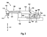
- Fig. 2 is a schematic simplified depiction of a personal hygiene device 100 comprising a treatment head 120 that is pivotably mounted at a handle 140 (here for sake of simplicity just indicated by a wall element).
- a coordinate system having x-, y-, and z-axis is shown as reference (the y-axis extends into the paper plane).
- the treatment head 120 is arranged to be moveable around a pivot axis 150 (here extending in y direction) against a spring force S provided by a resilient element 160 (which may have a linear spring constant at least in the range of forces that typically occur in a treatment session - i.e. treatment forces in the range of between about 0.5 Newton and about 7 Newton) arranged between the handle 140 and the treatment head 120.
- Provision of a pivot axis shall be considered as non-limiting and other linkages between treatment head and handle are considered as well.
- a treatment force F being applied at the treatment head 120 will cause such a deflection (here, the treatment force is applied at a front portion 110 of the treatment head 120).
- the applied treatment force F needs to have at least one force component that acts as a torque (i.e. moment of force) around the pivot axis 150.
- the treatment force F must initially have a component in the z direction; generally, the treatment force F must have a component that lies in a plane to which the pivot axis 150 is normal and which component is perpendicular to a radial line originating at the pivot axis and extending in said plane.
- the term "treatment force” in the present disclosure shall mean a force that has such a force component that can turn the treatment head 120 around the pivot axis 150 and all force values given herein, if not stated otherwise, relate to this force component.
- the personal hygiene device 100 generally extends in a longitudinal direction (here the x direction) between a first end (front portion 110 of the treatment head 120) and a second end (back end 149 of the handle 140).
- the front portion 110 of the treatment head 120 is here indicated as a brush head for use with an electric toothbrush.
- the front portion 110 has here a carrier element 112 (which may be mounted for movement relative to the treatment head 120) on which treatment elements 111 (here: cleaning elements such as tufts made from nylon filaments or elastomeric cleaning fingers etc.) are mounted.
- treatment elements 111 here: cleaning elements such as tufts made from nylon filaments or elastomeric cleaning fingers etc.
- the treatment head 120 may have a front arm 121 that extends from the pivot axis 150 to the front portion 110 and an arm element 122 that extends from the pivot axis 150 towards the back end of the handle 140.
- the arm element 122 tapers towards its back end; this shall be understood as just a non-limiting design option).
- a resilient element 160 (here indicated as a mechanical coil spring) is arranged between the handle 140 and the treatment head 120, here between handle 140 and arm element 122 of the treatment head 120.
- a first stopper 141 that is fixedly mounted with respect to the handle 140 is arranged so that a rest position of the treatment head 120 is defined when no treatment force F is applied.
- the rest position may be mechanically calibrated in a manner so that no biasing spring force S b acts against the treatment head 120.
- the rest position may be defined such that a biasing spring force S b ⁇ 0 Newton (N) acts against the treatment head 120 towards the first stopper 141 so that only an applied treatment force F that overcomes this biasing spring force S b (F > S b ) will move the treatment head 120 away from the first stopper 141 around the pivot axis 150.
- the biasing spring force S b may be set such that a treatment force F between 0.5 N and 2 N starts to move the treatment head 120.
- the biasing spring force S b may in particular be set such that a treatment force F of at least 0.5 N, 0.75 N, 1.0 N, 1.25 N, 1.5 N, 1.75 N, or 2.0 N starts to move the treatment head 120.
- the shown embodiment shall not exclude that at least a front portion of the treatment head is arranged to be repeatedly detachable from the handle and that at least a portion of the arm element 122 is non-detachably connected with the handle.
- the arm element 122 may then become connected with the treatment head 120 once it become attached to the handle 140 and then moves when the applied treatment force F deflects the treatment head 120.
- a second stopper 142 is mounted fixedly with respect to the handle 140 and defines a maximum deflection position of the treatment head 120. As indicated by dashed lines, the maximally deflected treatment head 120 abuts the second stopper 142 at abutment point 124.
- the first stopper 141 and the second stopper 142 define a maximum deflection range around the pivot axis 150 out of the rest position.
- the maximum deflection position provided by the second stopper 142 may be calibrated to relate to an applied treatment force in the range of between 2.5 N to 7.5 N and may in particular be set to 2.5 N, 3.0 N, 3.5 N, 4.0 N, 4.5 N, 5.0 N, 5.5 N, 6.0 N, 6.5 N, 7.0 N, or 7.5 N.
- the personal hygiene device 100 further comprises a treatment force measurement unit that includes a light emitting element 171, a light sensitive element 172, and a light changing element 180 arranged in a light path between the light emitting element 171 and the light sensitive element 172.
- the light changing element 180 is here shown as a light absorbing element. Alternatively or additionally, the light changing element 180 may be realized as a light reflecting element.
- the arm element 122 moves as a result of the relative movement of treatment head 120 and handle 140 and the relative position of the light changing element 180 with respect to at least one of the light emitting element 171 and the light sensitive element 172 is changed so that the light intensity measured by the light sensitive element 172 is changed (as indicated by double arrow M).
- the light intensity measured by the light sensitive element 172 is a parameter indicative of the value of the applied treatment force F.
- a signal value provided by the light sensitive element 172 can be calibrated so that a precise absolute value of the applied treatment force F can be determined.
- the maximum deflection of the elements of the treatment force measurement unit relatively to each other is the movement length.
- the length extension of the light changing element along the direction of the movement is in some embodiments longer than the movement length, in particular in some embodiments where the light changing element is realized as a translucent gray wedge.
- a SMD mountable phototransistor was used as light sensitive element, e.g. an Everlight PT12-21B/TR8 (EVERLIGHT ELECTRONICS CO., LTD., Taipei, Taiwan), which has a bandwidth of 400 nm to 1100 nm and peak sensitivity at 940 nm.
- a SMD mountable LED was used as light emitting element, e.g. an Everlight Right Angle Lens IR-12-21C/TR8, which has a peak wavelength at 940 nm and a spectral bandwidth of 45 nm.
- an Osram SFH 4045N LED having a peak wavelength of 950 nm was utilized.
- the Osram SFH 4045N LED has a small emission cone having a half angle of ⁇ 9 degrees.
- a confined and small emission cone tends to generation of less background noise. Background noise may be generated by light emitted at large angles, which light may eventually impinge onto the light sensitive element after having been reflected.
- an Everlight IR26-51C-L110 LED having a peak wavelength of 940 nm and a view angle of 20 degrees (i.e. a half angle of ⁇ 10 degrees) was used.
- the light changing element was made from polypropylene (PP) HW11L.
- the light changing element was made from polyoxymethylene (POM) Hostaform C9021 (available from Celanese GmbH, Sulzbach am Taunus, Germany).
- POM polyoxymethylene
- typical 1/e lengths' i.e. the length of material after which a light beam had been attenuated by 1/e (around 37%)
- typical 1/e lengths' i.e. the length of material after which a light beam had been attenuated by 1/e (around 37%)
- typical 1/e lengths' i.e. the length of material after which a light beam had been attenuated by 1/e (around 37%)
- typical 1/e lengths' i.e. the length of material after which a light beam had been attenuated by 1/e (around 37%)
- typical 1/e lengths' i.e. the length of material after which a light beam had been attenuated by 1/
- the light changing element was designed such that the attenuation between the extreme states of deflection was in a range of between about 1/e (about 37%) to about 50%.
- POM Hostaform C9021 white had been measured to have an attenuation coefficient of about 0.9 mm -1 (for IR radiation having a wavelength of 950 nm), which allowed relatively small sized light changing elements suitable for personal hygiene devices.
- Fig. 3 is a schematic and simplified depiction of various components of a personal hygiene device in accordance with the present disclosure including an example treatment force measurement unit 300 comprising a light emitting element 310 (which may be realized as an IR LED), a light sensitive element 320 (which may be realized as a phototransistor), a control circuit 330, and a light changing element 280, which is here without limitation shown as a gray wedge, which may in particular be realized as a translucent gray wedge, and in particular as a translucent gray wedge that always covers the sensitive area of the light sensitive element with respect to the light emitted by the light emitting element.
- an energy supply e.g. comprising a battery or an accumulator
- the light changing element 280 that is here secured at a moving portion 222 of a treatment head is moved under application of a treatment force F T against the restoring force F S of a resilient element 260 (here realized as a mechanical coil spring) along a movement direction indicated by double arrow M (as mentioned before, also other elements of the treatment force measurement unit may additionally or alternatively be arranged to be movable).
- the maximum deflection along movement direction is considered to be the movement length.
- the resilient element 260 is on one end secured with respect to a housing 240 of the personal hygiene device and on the other end it is secured with respect to the moving portion 222 (e.g. an arm element 122 as discussed with respect to Fig. 2 ).
- the light emitting element 310 has here a directional characteristic 311 with an intensity peak in the center (indicated by differently long arrows) so that light is essentially emitted along a light path 312 directed towards a center of a sensitive area of the light sensitive element 320.
- Light absorbing surfaces 390-393 are schematically indicated, which may be arranged in proximity of the light path 312 so that light that is e.g. emitted at large angles from the light emitting element 310 or light that is scattered away by the light changing element 280 is absorbed. Otherwise scattered light or light emitted at large angles may become reflected by non-absorbing surfaces and may then eventually impinge onto the sensitive area of the light sensitive element 320, which would distort the light intensity measurement.
- the number and position of the light absorbing surfaces is within the discretion of the designer. In some embodiments, only a single light absorbing surface may be present, in other embodiments, several light absorbing surfaces are utilized.
- light impinging onto the active light sensitive element 320 leads to a light-intensity depending current flow through a resistor R, which changing current flow then leads to a change in the voltage over the resistor R. The voltage over the resistor R is measured by the control circuit 330.
- the control circuit 330 has an input I via whom the control circuit 330 may receive a signal when the personal hygiene device is switched on. The control circuit 330 may then activate the light emitting element 310 and the light sensitive element 320 by switching on respective switches 319 and 329. The control circuit 330 may compare the voltage over the resistor R with at least a first pre-determined threshold voltage V T1 , so that based on this comparison, a signal S indicates whether the measured voltage is above or below the first pre-determined threshold voltage V T1 .
- the first pre-determined threshold voltage V T1 may be calibrated such that it relates to a first pre-determined treatment force value of, e.g., 1.5 N or 2 N as discussed before. Based on the comparison result (i.e.
- the control circuit 330 can control at least a first indication element 340 to provide a user noticeable signal (e.g. a visual signal, an audible signal, or a tactile signal).
- the first indication element 340 may thus be realized as a light emission element such as an LED, as a loudspeaker, or as a vibrator, e.g. a piezo-vibrator.
- the first indication element 340 can then be activated as long as the applied treatment force F T has a value that is below (or above) a first pre-determined treatment force value.
- At least a second pre-determined threshold voltage may be provided (which may e.g. be calibrated to a second pre-determined treatment force value of e.g.
- the control circuit 330 can then indicate via the first indication element 340 that the applied treatment force F T is between the first and the second pre-determined treatment force values.
- At least a second indication element 341 may be provided to indicate e.g. that the applied treatment force F T is above the second pre-determined treatment force value.
- the second indication element 341 may be realized as one from the list of realization possibilities given above for the first indication element.
- the first indication element 340 may be realized as a green LED, while the second indication element 342 may be realized as a red LED.
- the control circuit 330 is calibrated so that the absolute value of signal S relates to a treatment force value and the precise application of treatment forces over time can be monitored and analyzed.
- control circuit 330 comprises a drift compensation circuit 400 for determining a reference voltage representing zero applied treatment force, in particular wherein the drift compensation circuit is arranged to apply a median value determination based on voltage signals prior to an instant when the personal hygiene device is switched on.
- control circuit 330 comprises a temperature correction unit 500 comprising a temperature sensor 510 and a temperature correction circuit 520.
- the temperature correction circuit 520 may be arranged to correct the voltage value measured by the control circuit 330 for temperature depending effects.
- the personal hygiene device comprises a transmitter unit 600 for establishing at least a one-directional wireless connection with an external device, e.g. for communicating data from the personal hygiene device to the external device, in particular for the purpose of analyzing and/or displaying information about the treatment session to the user.
- Fig. 3 also indicates that in some embodiments additional components may be present such as, e.g., an automatic adjustment circuit 700 and/or a user input unit 800.
- the personal hygiene device may have a drift compensation circuit for correcting a drift in the output signal of the light sensitive element over time, e.g. due to aging.
- the drift compensation circuit determines the output signal of the light sensitive element for zero applied treatment force.
- the drift compensation circuit reads the output signal from the activated light sensitive element during a given time period (which may happen, e.g., once every month, even though this shall not exclude that the drift compensation circuit stores output signal values always while the personal hygiene device is switched off) and writes the output signals into an internal memory.
- the drift compensation circuit may thus be arranged to wake the treatment force measurement unit.
- the drift compensation circuit stops storing output signals to not falsify the measurement due to forces being applied at the treatment head. If not enough output signal values were stored up the instant the personal hygiene device was eventually switched on, the drift compensation circuit may be arranged to repeat the procedure, e.g. 6 hours later.
- the drift compensation circuit may be arranged to read output signal values from the light sensitive element at a frequency in the range of between about 0.5 Hz to 5 Hz, even though these values are not to be construed as limiting.
- the drift compensation circuit may store the output signal values into the memory for a period of between about 1 second to about 600 seconds. As it cannot be ensured that the user does not use the personal hygiene device prior to switching it on (e.g.
- a user of a toothbrush may hold the brush head under water prior to applying toothpaste, which are both acts during which a force is applied at the treatment head leading to a respective change of the output signal of the light sensitive element), the drift compensation circuit may apply a median filtering by which extreme output signal values are filtered out.
- the computed median value was found to be reliable with a error in the range of 0.044 N for a sample rate of 1 Hz and a data collection of 10 output signal values during which the toothbrush was used prior to switching it on.
- the personal hygiene device comprises an acceleration sensor and output signal values are not stored while the toothbrush is moved. The thus computed zero treatment force output signal value is then used by the treatment force measurement unit for zero treatment force calibrated measurements until a new value is provided by the drift compensation circuit.
- the personal hygiene device is arranged to detect whether it is placed on a holder (e.g. a charger), under which circumstances the drift compensation circuit may be arranged to wake the treatment force measurement unit to record output signals from the light sensitive element as it should be a reliable assumption that no force is applied at the treatment head while the personal hygiene device is placed on the holder.
- a holder e.g. a charger
- the personal hygiene device as disclosed herein may be calibrated, e.g. at the plant of the manufacturer.
- a series of at least two or more precisely controlled load values may be applied at the treatment head so that the treatment force measurement unit can calibrate the signals from the light sensitive element versus the applied force values.
- the personal hygiene device may be provided with a particular calibration mode in which the respective force values to be applied during calibration are pre-programmed and the parameter values which are measured during the calibration procedure are then used for a respective calibration.
- the personal hygiene device can communicate with an external device (a wired or wireless connection may be used) via which the applied load values are communicated from the external device to the personal hygiene device for using these values in the calibration.
- the signals from the light sensitive element may be communicated from the personal hygiene device to the external device, which then performs the calibration and communicates back calibration parameters to be applied. In the latter embodiment, a complex calibration circuit is not necessary in the personal hygiene device.
- the personal hygiene device may be equipped with a user input unit for adjusting at least one of the pre-determined treatment force threshold values (or for adjusting the pre-determined treatment force threshold value if only one such value is set).
- a user input unit may be realized as a simple switch or as a touch-sensitive pad.
- the user input unit is realized as a wireless connectable receiver or transceiver for receiving (and optionally transmitting) data between an external device (e.g. a smartphone onto which a suitable application was loaded) and the personal hygiene device. In the latter embodiment, comfortable and manifold setting possibilities can be realized without the need to realize the respective complex user input unit in the personal hygiene device.
- the personal hygiene device is arranged for an automatic adjustment when a treatment mode of the personal hygiene device is changed.
- a treatment mode of the personal hygiene device is changed.
- it is known to provide different brushing modes such as "Standard Cleaning Mode", “Soft Cleaning Mode”, or "Gum Care Mode”.
- the pre-determined treatment force threshold value for the applied treatment force may be set to 3 N for the "Standard Cleaning Mode”
- the pre-determined treatment force threshold value may be changed to 2.5 N in case the "Soft Cleaning Mode” is chosen or e.g. to 2.0 N if the "Gum Care Mode” is chosen.
- the device can then indicate a dedicated too high treatment force.
- the personal hygiene device (in particular the treatment force measurement unit) is arranged to measure a time series of applied treatment force values and to automatically adjust the pre-determined treatment force threshold value(s) based on the habits of the user.
- An automatic adjustment unit may be provided for performing the mentioned automatic adjustments.
Landscapes
- Health & Medical Sciences (AREA)
- Dentistry (AREA)
- General Health & Medical Sciences (AREA)
- Physics & Mathematics (AREA)
- Epidemiology (AREA)
- Life Sciences & Earth Sciences (AREA)
- Animal Behavior & Ethology (AREA)
- Public Health (AREA)
- Veterinary Medicine (AREA)
- Optics & Photonics (AREA)
- Acoustics & Sound (AREA)
- Brushes (AREA)
Priority Applications (7)
| Application Number | Priority Date | Filing Date | Title |
|---|---|---|---|
| EP15167364.7A EP3092974B1 (fr) | 2015-05-12 | 2015-05-12 | Dispositif d'hygiène personnel avec unité de mesure de force de traitement |
| ES15167364.7T ES2670015T3 (es) | 2015-05-12 | 2015-05-12 | Dispositivo de higiene personal con unidad de medición de la fuerza de tratamiento |
| JP2017558707A JP2018514336A (ja) | 2015-05-12 | 2016-05-03 | 処置力測定ユニットを備えた個人衛生装置 |
| CA2982713A CA2982713A1 (fr) | 2015-05-12 | 2016-05-03 | Dispositif d'hygiene corporelle dote d'une unite de mesure de force de traitement |
| PCT/IB2016/052514 WO2016181255A1 (fr) | 2015-05-12 | 2016-05-03 | Dispositif d'hygiène corporelle doté d'une unité de mesure de force de traitement |
| CN201680027413.6A CN107580466B (zh) | 2015-05-12 | 2016-05-03 | 具有处理力测量单元的个人卫生装置 |
| US15/153,708 US10433636B2 (en) | 2015-05-12 | 2016-05-12 | Personal hygiene device having treatment-force-measurement unit |
Applications Claiming Priority (1)
| Application Number | Priority Date | Filing Date | Title |
|---|---|---|---|
| EP15167364.7A EP3092974B1 (fr) | 2015-05-12 | 2015-05-12 | Dispositif d'hygiène personnel avec unité de mesure de force de traitement |
Publications (2)
| Publication Number | Publication Date |
|---|---|
| EP3092974A1 true EP3092974A1 (fr) | 2016-11-16 |
| EP3092974B1 EP3092974B1 (fr) | 2018-03-07 |
Family
ID=53175333
Family Applications (1)
| Application Number | Title | Priority Date | Filing Date |
|---|---|---|---|
| EP15167364.7A Active EP3092974B1 (fr) | 2015-05-12 | 2015-05-12 | Dispositif d'hygiène personnel avec unité de mesure de force de traitement |
Country Status (7)
| Country | Link |
|---|---|
| US (1) | US10433636B2 (fr) |
| EP (1) | EP3092974B1 (fr) |
| JP (1) | JP2018514336A (fr) |
| CN (1) | CN107580466B (fr) |
| CA (1) | CA2982713A1 (fr) |
| ES (1) | ES2670015T3 (fr) |
| WO (1) | WO2016181255A1 (fr) |
Cited By (4)
| Publication number | Priority date | Publication date | Assignee | Title |
|---|---|---|---|---|
| CN107753134A (zh) * | 2017-11-14 | 2018-03-06 | 上海携福电器有限公司 | 用于电动清洁护理器具的光敏压力报警装置 |
| EP3556247A1 (fr) | 2018-04-18 | 2019-10-23 | Braun GmbH | Dispositif d'hygiène personnel comportant une unité de mesure de force de traitement |
| KR20200057748A (ko) * | 2017-11-02 | 2020-05-26 | 브라운 게엠베하 | 개인 위생 장치 |
| CN115603539A (zh) * | 2021-06-28 | 2023-01-13 | 上海携福电器有限公司(Cn) | 清洁护理用具及其换能装置和压力报警机构 |
Families Citing this family (11)
| Publication number | Priority date | Publication date | Assignee | Title |
|---|---|---|---|---|
| US9718594B2 (en) * | 2012-02-10 | 2017-08-01 | The Gillette Company Llc | Oral care instrument and package therefore |
| EP3086628B1 (fr) | 2015-04-21 | 2018-07-18 | Braun GmbH | Composant électrique spécial, ensemble de carte de circuit imprimé et procédé de fabrication d'un appareil électrique |
| ES2670015T3 (es) * | 2015-05-12 | 2018-05-29 | Braun Gmbh | Dispositivo de higiene personal con unidad de medición de la fuerza de tratamiento |
| US10653236B2 (en) * | 2016-03-30 | 2020-05-19 | Koninklijke Philips N.V. | Methods and systems for calibrating an oral cleaning device |
| WO2017202913A1 (fr) * | 2016-05-24 | 2017-11-30 | Koninklijke Philips N.V. | Procédés et systèmes de détection optique de forces dans une brosse à dents |
| CN107898518A (zh) * | 2017-11-28 | 2018-04-13 | 深圳市奇异鸟科技有限公司 | 一种电动牙刷及电动牙刷控制方法 |
| US11100350B2 (en) * | 2018-02-19 | 2021-08-24 | Avigilon Corporation | Method and system for object classification using visible and invisible light images |
| DE102019120648B4 (de) | 2018-08-02 | 2026-02-12 | Ranir, Llc | Drucksensorsystem und Verfahren für eine elektrische Zahnbürste |
| CN112006800B (zh) * | 2019-05-29 | 2025-08-05 | 上海携福电器有限公司 | 声波类电动清洁护理器具 |
| WO2022120671A1 (fr) * | 2020-12-10 | 2022-06-16 | Colgate-Palmolive Company | Instrument de soins buccaux et poignée de cet instrument |
| EP4717120A1 (fr) * | 2024-09-30 | 2026-04-01 | Koninklijke Philips N.V. | Compensation de température dans des capteurs optiques pour dispositifs de nettoyage buccal |
Citations (2)
| Publication number | Priority date | Publication date | Assignee | Title |
|---|---|---|---|---|
| DE3414623C1 (de) | 1984-04-18 | 1985-10-10 | Blendax-Werke R. Schneider Gmbh & Co, 6500 Mainz | Zahnbuerste |
| US5493747A (en) * | 1993-07-27 | 1996-02-27 | Matsushita Electric Works, Ltd. | Electric toothbrush |
Family Cites Families (41)
| Publication number | Priority date | Publication date | Assignee | Title |
|---|---|---|---|---|
| JPS50105335A (fr) | 1974-01-26 | 1975-08-20 | ||
| JPS565169Y2 (fr) * | 1974-02-07 | 1981-02-04 | ||
| US3986037A (en) * | 1975-10-03 | 1976-10-12 | E. I. Du Pont De Nemours And Company | Yarn detector with a self-calibrating circuit |
| US4495819A (en) * | 1982-12-23 | 1985-01-29 | Gould Inc. | Optical pressure sensor |
| JPS60151051A (ja) * | 1984-01-18 | 1985-08-08 | Toppan Printing Co Ltd | 平台校正印刷機 |
| JPS63201504A (ja) * | 1987-02-18 | 1988-08-19 | Rion Co Ltd | 光学式物理量測定装置 |
| SU1508091A1 (ru) | 1987-10-26 | 1989-09-15 | Всесоюзный научно-исследовательский институт электроизмерительных приборов | Бесконтактный преобразователь линейных перемещений |
| AT388830B (de) * | 1988-01-25 | 1989-09-11 | Avl Verbrennungskraft Messtech | Ladungsverstaerkerschaltung |
| GB8810214D0 (en) | 1988-04-29 | 1988-06-02 | Lucas Ind Plc | Movement transducer |
| DE3923495C1 (fr) * | 1989-07-15 | 1991-01-24 | M + C Schiffer Gmbh, 5466 Neustadt, De | |
| JPH04184204A (ja) * | 1990-11-20 | 1992-07-01 | Canon Inc | 原稿検知装置 |
| JPH05237014A (ja) * | 1992-02-27 | 1993-09-17 | Tokyo Electric Co Ltd | 電動歯ブラシ |
| US5282291A (en) * | 1992-09-16 | 1994-02-01 | Bioware Inc. | Force sensitive handle for hand operated implement |
| JPH0814943A (ja) * | 1994-06-30 | 1996-01-19 | Shimadzu Corp | 変位量検出装置 |
| US5690486A (en) * | 1995-07-28 | 1997-11-25 | Dentalase Corporation | Dental tooth color detector apparatus and method |
| US6073262A (en) * | 1997-05-30 | 2000-06-06 | United Technologies Corporation | Method and apparatus for estimating an actual magnitude of a physical parameter on the basis of three or more redundant signals |
| JP3369467B2 (ja) * | 1998-04-24 | 2003-01-20 | 日野自動車株式会社 | 車両の重心高さの推定演算装置 |
| JP2000310509A (ja) * | 1999-04-28 | 2000-11-07 | Toshiba Corp | ストローク測定装置 |
| US7281289B1 (en) * | 1999-09-17 | 2007-10-16 | Placontrol, Inc. | Automatic pressure release toothbrush |
| US6690505B1 (en) * | 2001-09-28 | 2004-02-10 | Onetta, Inc. | Optical network equipment with gain transient control and automatic drift compensation |
| CA2390411A1 (fr) * | 2002-06-03 | 2003-12-03 | Alwin Manufacturing Company, Incorporated | Distributeur automatique |
| US7541569B1 (en) * | 2002-08-16 | 2009-06-02 | Raytheon Company | Position sensor utilizing light emissions from a lateral surface of an optical fiber |
| US7428054B2 (en) * | 2002-10-15 | 2008-09-23 | University Of Maryland | Micro-optical sensor system for pressure, acceleration, and pressure gradient measurements |
| JP2005156549A (ja) * | 2003-11-05 | 2005-06-16 | Sendai Nikon:Kk | 光学式エンコーダ |
| US20050151975A1 (en) * | 2004-01-14 | 2005-07-14 | Ivan Melnyk | Fabry-perot fiber optic sensing device and method |
| US8463084B2 (en) * | 2004-12-16 | 2013-06-11 | Kulite Semiconductor Products, Inc. | Optical micromachined pressure sensor |
| JP4616695B2 (ja) * | 2005-05-10 | 2011-01-19 | 三菱重工業株式会社 | マルチセンサ信号異常検知装置および方法 |
| US7453986B1 (en) * | 2005-05-31 | 2008-11-18 | Wideband Computers, Inc. | Digital dental image apparatus |
| JP2006337134A (ja) * | 2005-06-01 | 2006-12-14 | Konica Minolta Medical & Graphic Inc | 流量測定装置及び流量測定方法 |
| JP5293101B2 (ja) * | 2008-03-14 | 2013-09-18 | オムロンヘルスケア株式会社 | 電動歯ブラシ |
| GB0810317D0 (en) * | 2008-06-05 | 2008-07-09 | King S College London | Sensor |
| PL2218559T3 (pl) * | 2009-02-13 | 2013-01-31 | Edgewell Personal Care Brands Llc | Urządzenie do pielęgnacji ciała |
| US8199334B2 (en) * | 2009-03-30 | 2012-06-12 | General Electric Company | Self-calibrated interrogation system for optical sensors |
| PL2445374T3 (pl) * | 2009-06-26 | 2017-04-28 | The Gillette Company | Wskaźnik nacisku dla szczoteczki do zębów |
| US8879067B2 (en) * | 2010-09-01 | 2014-11-04 | Lake Shore Cryotronics, Inc. | Wavelength dependent optical force sensing |
| US9549841B2 (en) * | 2011-05-10 | 2017-01-24 | Split Rock Scientific, Inc. | System and method for delivering a therapy and sensing a biological activity in the mouth |
| WO2012156496A2 (fr) * | 2011-05-19 | 2012-11-22 | W & H Dentalwerk Bürmoos GmbH | Instrument médical, notamment dentaire, comportant un dispositif de mesure de la température |
| CN103876849B (zh) * | 2012-12-21 | 2017-05-31 | 高露洁-棕榄公司 | 具有压力传感器的口腔护理器具及其形成方法 |
| US20140310900A1 (en) * | 2013-03-05 | 2014-10-23 | Beam Technologies, Llc | Toothbrush and System with Sensors and User Identification |
| US9804050B2 (en) * | 2013-03-14 | 2017-10-31 | Kulite Semiconductor Products, Inc. | Systems and methods for sensor drift compensation |
| ES2670015T3 (es) * | 2015-05-12 | 2018-05-29 | Braun Gmbh | Dispositivo de higiene personal con unidad de medición de la fuerza de tratamiento |
-
2015
- 2015-05-12 ES ES15167364.7T patent/ES2670015T3/es active Active
- 2015-05-12 EP EP15167364.7A patent/EP3092974B1/fr active Active
-
2016
- 2016-05-03 CN CN201680027413.6A patent/CN107580466B/zh active Active
- 2016-05-03 CA CA2982713A patent/CA2982713A1/fr not_active Abandoned
- 2016-05-03 JP JP2017558707A patent/JP2018514336A/ja active Pending
- 2016-05-03 WO PCT/IB2016/052514 patent/WO2016181255A1/fr not_active Ceased
- 2016-05-12 US US15/153,708 patent/US10433636B2/en active Active
Patent Citations (3)
| Publication number | Priority date | Publication date | Assignee | Title |
|---|---|---|---|---|
| DE3414623C1 (de) | 1984-04-18 | 1985-10-10 | Blendax-Werke R. Schneider Gmbh & Co, 6500 Mainz | Zahnbuerste |
| US4698869A (en) * | 1984-04-18 | 1987-10-13 | Blendax-Werke R. Schneider Gmbh & Co. | Toothbrush |
| US5493747A (en) * | 1993-07-27 | 1996-02-27 | Matsushita Electric Works, Ltd. | Electric toothbrush |
Non-Patent Citations (1)
| Title |
|---|
| "Sensors for Mechanotronics", 1 October 2012, ELSEVIER, St. Louis, MO, USA, article PAUL P L REGTIEN: "Force, Torque and Strain Sensing", pages: 211 - 213, XP055218855 * |
Cited By (8)
| Publication number | Priority date | Publication date | Assignee | Title |
|---|---|---|---|---|
| KR20200057748A (ko) * | 2017-11-02 | 2020-05-26 | 브라운 게엠베하 | 개인 위생 장치 |
| JP2021500149A (ja) * | 2017-11-02 | 2021-01-07 | ブラウン ゲーエムベーハー | 個人衛生装置 |
| JP7324748B2 (ja) | 2017-11-02 | 2023-08-10 | ブラウン ゲーエムベーハー | 個人衛生装置 |
| CN107753134A (zh) * | 2017-11-14 | 2018-03-06 | 上海携福电器有限公司 | 用于电动清洁护理器具的光敏压力报警装置 |
| CN107753134B (zh) * | 2017-11-14 | 2023-12-08 | 上海携福电器有限公司 | 用于电动清洁护理器具的光敏压力报警装置 |
| EP3556247A1 (fr) | 2018-04-18 | 2019-10-23 | Braun GmbH | Dispositif d'hygiène personnel comportant une unité de mesure de force de traitement |
| WO2019202470A1 (fr) | 2018-04-18 | 2019-10-24 | Braun Gmbh | Dispositif d'hygiène personnelle doté d'une unité de mesure de force de traitement |
| CN115603539A (zh) * | 2021-06-28 | 2023-01-13 | 上海携福电器有限公司(Cn) | 清洁护理用具及其换能装置和压力报警机构 |
Also Published As
| Publication number | Publication date |
|---|---|
| ES2670015T3 (es) | 2018-05-29 |
| EP3092974B1 (fr) | 2018-03-07 |
| CN107580466A (zh) | 2018-01-12 |
| CA2982713A1 (fr) | 2016-11-17 |
| CN107580466B (zh) | 2020-05-05 |
| US10433636B2 (en) | 2019-10-08 |
| JP2018514336A (ja) | 2018-06-07 |
| US20160331120A1 (en) | 2016-11-17 |
| WO2016181255A1 (fr) | 2016-11-17 |
Similar Documents
| Publication | Publication Date | Title |
|---|---|---|
| EP3092974B1 (fr) | Dispositif d'hygiène personnel avec unité de mesure de force de traitement | |
| RU2662072C2 (ru) | Электрическая зубная щетка | |
| US11517219B2 (en) | Biological information measurement apparatus | |
| CN100388626C (zh) | 光电传感器及其调整方法 | |
| US6095812A (en) | Device for curing with light | |
| US7221435B2 (en) | Device and method for optical distance measurement | |
| US20130321359A1 (en) | Stylus with pressure sensor | |
| US10548491B2 (en) | Photoplethysmography apparatus | |
| MX2013001027A (es) | Sensor de desgaste de freno de freno de disco. | |
| KR101448393B1 (ko) | 의료용 레이저 수신단의 apd 이득 안정화 방법 | |
| CN113874749A (zh) | 具有污物检测的激光传感器模块 | |
| EP1703265A3 (fr) | Capteur à fibres optiques avec un codeur rotatif pour ajustement de paramètres | |
| WO2018158276A1 (fr) | Procédé de détermination des conditions de fonctionnement d'un détecteur de particules à base de laser | |
| US12279683B2 (en) | Skin treatment system | |
| US20130018626A1 (en) | Non-contact type temperature sensing device with constant distance measurement and temperature measuring method thereof | |
| CA3060377C (fr) | Procede, appareil et produit programme d'ordinateur pour commander des composants d'un dispositif de detection | |
| US6524243B1 (en) | Tonometer incorporating an electrical measurement device | |
| EP2521481A1 (fr) | Système, dispositif et procédé de détermination d'une érosion dentaire | |
| JPH02295542A (ja) | 光センサ | |
| JP2015192742A (ja) | 脈波検出装置 | |
| CN112213241A (zh) | 尘埃堆积探测装置 | |
| US20060270925A1 (en) | Tonometer apparatus | |
| CN116724275A (zh) | 用于检测沿轴线的运动的仪器和方法 | |
| CN117990217A (zh) | 温度传感装置 | |
| CN110301898A (zh) | 生物信息测量设备、方法、系统和计算机可读介质 |
Legal Events
| Date | Code | Title | Description |
|---|---|---|---|
| PUAI | Public reference made under article 153(3) epc to a published international application that has entered the european phase |
Free format text: ORIGINAL CODE: 0009012 |
|
| AK | Designated contracting states |
Kind code of ref document: A1 Designated state(s): AL AT BE BG CH CY CZ DE DK EE ES FI FR GB GR HR HU IE IS IT LI LT LU LV MC MK MT NL NO PL PT RO RS SE SI SK SM TR |
|
| AX | Request for extension of the european patent |
Extension state: BA ME |
|
| 17P | Request for examination filed |
Effective date: 20170515 |
|
| RBV | Designated contracting states (corrected) |
Designated state(s): AL AT BE BG CH CY CZ DE DK EE ES FI FR GB GR HR HU IE IS IT LI LT LU LV MC MK MT NL NO PL PT RO RS SE SI SK SM TR |
|
| GRAP | Despatch of communication of intention to grant a patent |
Free format text: ORIGINAL CODE: EPIDOSNIGR1 |
|
| INTG | Intention to grant announced |
Effective date: 20171013 |
|
| GRAS | Grant fee paid |
Free format text: ORIGINAL CODE: EPIDOSNIGR3 |
|
| GRAA | (expected) grant |
Free format text: ORIGINAL CODE: 0009210 |
|
| AK | Designated contracting states |
Kind code of ref document: B1 Designated state(s): AL AT BE BG CH CY CZ DE DK EE ES FI FR GB GR HR HU IE IS IT LI LT LU LV MC MK MT NL NO PL PT RO RS SE SI SK SM TR |
|
| REG | Reference to a national code |
Ref country code: GB Ref legal event code: FG4D |
|
| REG | Reference to a national code |
Ref country code: CH Ref legal event code: EP Ref country code: AT Ref legal event code: REF Ref document number: 975721 Country of ref document: AT Kind code of ref document: T Effective date: 20180315 |
|
| REG | Reference to a national code |
Ref country code: IE Ref legal event code: FG4D |
|
| REG | Reference to a national code |
Ref country code: DE Ref legal event code: R096 Ref document number: 602015008522 Country of ref document: DE |
|
| REG | Reference to a national code |
Ref country code: FR Ref legal event code: PLFP Year of fee payment: 4 |
|
| REG | Reference to a national code |
Ref country code: ES Ref legal event code: FG2A Ref document number: 2670015 Country of ref document: ES Kind code of ref document: T3 Effective date: 20180529 |
|
| REG | Reference to a national code |
Ref country code: NL Ref legal event code: FP |
|
| REG | Reference to a national code |
Ref country code: SE Ref legal event code: TRGR |
|
| REG | Reference to a national code |
Ref country code: LT Ref legal event code: MG4D |
|
| PG25 | Lapsed in a contracting state [announced via postgrant information from national office to epo] |
Ref country code: FI Free format text: LAPSE BECAUSE OF FAILURE TO SUBMIT A TRANSLATION OF THE DESCRIPTION OR TO PAY THE FEE WITHIN THE PRESCRIBED TIME-LIMIT Effective date: 20180307 Ref country code: LT Free format text: LAPSE BECAUSE OF FAILURE TO SUBMIT A TRANSLATION OF THE DESCRIPTION OR TO PAY THE FEE WITHIN THE PRESCRIBED TIME-LIMIT Effective date: 20180307 Ref country code: CY Free format text: LAPSE BECAUSE OF FAILURE TO SUBMIT A TRANSLATION OF THE DESCRIPTION OR TO PAY THE FEE WITHIN THE PRESCRIBED TIME-LIMIT Effective date: 20180307 Ref country code: NO Free format text: LAPSE BECAUSE OF FAILURE TO SUBMIT A TRANSLATION OF THE DESCRIPTION OR TO PAY THE FEE WITHIN THE PRESCRIBED TIME-LIMIT Effective date: 20180607 Ref country code: HR Free format text: LAPSE BECAUSE OF FAILURE TO SUBMIT A TRANSLATION OF THE DESCRIPTION OR TO PAY THE FEE WITHIN THE PRESCRIBED TIME-LIMIT Effective date: 20180307 |
|
| PGFP | Annual fee paid to national office [announced via postgrant information from national office to epo] |
Ref country code: ES Payment date: 20180601 Year of fee payment: 4 |
|
| REG | Reference to a national code |
Ref country code: AT Ref legal event code: MK05 Ref document number: 975721 Country of ref document: AT Kind code of ref document: T Effective date: 20180307 |
|
| PG25 | Lapsed in a contracting state [announced via postgrant information from national office to epo] |
Ref country code: BG Free format text: LAPSE BECAUSE OF FAILURE TO SUBMIT A TRANSLATION OF THE DESCRIPTION OR TO PAY THE FEE WITHIN THE PRESCRIBED TIME-LIMIT Effective date: 20180607 Ref country code: RS Free format text: LAPSE BECAUSE OF FAILURE TO SUBMIT A TRANSLATION OF THE DESCRIPTION OR TO PAY THE FEE WITHIN THE PRESCRIBED TIME-LIMIT Effective date: 20180307 Ref country code: LV Free format text: LAPSE BECAUSE OF FAILURE TO SUBMIT A TRANSLATION OF THE DESCRIPTION OR TO PAY THE FEE WITHIN THE PRESCRIBED TIME-LIMIT Effective date: 20180307 Ref country code: GR Free format text: LAPSE BECAUSE OF FAILURE TO SUBMIT A TRANSLATION OF THE DESCRIPTION OR TO PAY THE FEE WITHIN THE PRESCRIBED TIME-LIMIT Effective date: 20180608 |
|
| PG25 | Lapsed in a contracting state [announced via postgrant information from national office to epo] |
Ref country code: IT Free format text: LAPSE BECAUSE OF FAILURE TO SUBMIT A TRANSLATION OF THE DESCRIPTION OR TO PAY THE FEE WITHIN THE PRESCRIBED TIME-LIMIT Effective date: 20180307 Ref country code: PL Free format text: LAPSE BECAUSE OF FAILURE TO SUBMIT A TRANSLATION OF THE DESCRIPTION OR TO PAY THE FEE WITHIN THE PRESCRIBED TIME-LIMIT Effective date: 20180307 Ref country code: EE Free format text: LAPSE BECAUSE OF FAILURE TO SUBMIT A TRANSLATION OF THE DESCRIPTION OR TO PAY THE FEE WITHIN THE PRESCRIBED TIME-LIMIT Effective date: 20180307 Ref country code: RO Free format text: LAPSE BECAUSE OF FAILURE TO SUBMIT A TRANSLATION OF THE DESCRIPTION OR TO PAY THE FEE WITHIN THE PRESCRIBED TIME-LIMIT Effective date: 20180307 Ref country code: AL Free format text: LAPSE BECAUSE OF FAILURE TO SUBMIT A TRANSLATION OF THE DESCRIPTION OR TO PAY THE FEE WITHIN THE PRESCRIBED TIME-LIMIT Effective date: 20180307 |
|
| PG25 | Lapsed in a contracting state [announced via postgrant information from national office to epo] |
Ref country code: AT Free format text: LAPSE BECAUSE OF FAILURE TO SUBMIT A TRANSLATION OF THE DESCRIPTION OR TO PAY THE FEE WITHIN THE PRESCRIBED TIME-LIMIT Effective date: 20180307 Ref country code: SK Free format text: LAPSE BECAUSE OF FAILURE TO SUBMIT A TRANSLATION OF THE DESCRIPTION OR TO PAY THE FEE WITHIN THE PRESCRIBED TIME-LIMIT Effective date: 20180307 Ref country code: SM Free format text: LAPSE BECAUSE OF FAILURE TO SUBMIT A TRANSLATION OF THE DESCRIPTION OR TO PAY THE FEE WITHIN THE PRESCRIBED TIME-LIMIT Effective date: 20180307 Ref country code: CZ Free format text: LAPSE BECAUSE OF FAILURE TO SUBMIT A TRANSLATION OF THE DESCRIPTION OR TO PAY THE FEE WITHIN THE PRESCRIBED TIME-LIMIT Effective date: 20180307 |
|
| REG | Reference to a national code |
Ref country code: DE Ref legal event code: R097 Ref document number: 602015008522 Country of ref document: DE |
|
| PG25 | Lapsed in a contracting state [announced via postgrant information from national office to epo] |
Ref country code: PT Free format text: LAPSE BECAUSE OF FAILURE TO SUBMIT A TRANSLATION OF THE DESCRIPTION OR TO PAY THE FEE WITHIN THE PRESCRIBED TIME-LIMIT Effective date: 20180709 |
|
| PLBE | No opposition filed within time limit |
Free format text: ORIGINAL CODE: 0009261 |
|
| STAA | Information on the status of an ep patent application or granted ep patent |
Free format text: STATUS: NO OPPOSITION FILED WITHIN TIME LIMIT |
|
| REG | Reference to a national code |
Ref country code: BE Ref legal event code: MM Effective date: 20180531 |
|
| PG25 | Lapsed in a contracting state [announced via postgrant information from national office to epo] |
Ref country code: DK Free format text: LAPSE BECAUSE OF FAILURE TO SUBMIT A TRANSLATION OF THE DESCRIPTION OR TO PAY THE FEE WITHIN THE PRESCRIBED TIME-LIMIT Effective date: 20180307 Ref country code: MC Free format text: LAPSE BECAUSE OF FAILURE TO SUBMIT A TRANSLATION OF THE DESCRIPTION OR TO PAY THE FEE WITHIN THE PRESCRIBED TIME-LIMIT Effective date: 20180307 |
|
| 26N | No opposition filed |
Effective date: 20181210 |
|
| REG | Reference to a national code |
Ref country code: IE Ref legal event code: MM4A |
|
| PG25 | Lapsed in a contracting state [announced via postgrant information from national office to epo] |
Ref country code: SI Free format text: LAPSE BECAUSE OF FAILURE TO SUBMIT A TRANSLATION OF THE DESCRIPTION OR TO PAY THE FEE WITHIN THE PRESCRIBED TIME-LIMIT Effective date: 20180307 |
|
| PG25 | Lapsed in a contracting state [announced via postgrant information from national office to epo] |
Ref country code: LU Free format text: LAPSE BECAUSE OF NON-PAYMENT OF DUE FEES Effective date: 20180512 |
|
| PG25 | Lapsed in a contracting state [announced via postgrant information from national office to epo] |
Ref country code: IE Free format text: LAPSE BECAUSE OF NON-PAYMENT OF DUE FEES Effective date: 20180512 |
|
| PG25 | Lapsed in a contracting state [announced via postgrant information from national office to epo] |
Ref country code: BE Free format text: LAPSE BECAUSE OF NON-PAYMENT OF DUE FEES Effective date: 20180531 |
|
| PGFP | Annual fee paid to national office [announced via postgrant information from national office to epo] |
Ref country code: SE Payment date: 20190513 Year of fee payment: 5 |
|
| PGFP | Annual fee paid to national office [announced via postgrant information from national office to epo] |
Ref country code: CH Payment date: 20190516 Year of fee payment: 5 |
|
| PG25 | Lapsed in a contracting state [announced via postgrant information from national office to epo] |
Ref country code: MT Free format text: LAPSE BECAUSE OF NON-PAYMENT OF DUE FEES Effective date: 20180512 |
|
| PG25 | Lapsed in a contracting state [announced via postgrant information from national office to epo] |
Ref country code: TR Free format text: LAPSE BECAUSE OF FAILURE TO SUBMIT A TRANSLATION OF THE DESCRIPTION OR TO PAY THE FEE WITHIN THE PRESCRIBED TIME-LIMIT Effective date: 20180307 |
|
| PG25 | Lapsed in a contracting state [announced via postgrant information from national office to epo] |
Ref country code: HU Free format text: LAPSE BECAUSE OF FAILURE TO SUBMIT A TRANSLATION OF THE DESCRIPTION OR TO PAY THE FEE WITHIN THE PRESCRIBED TIME-LIMIT; INVALID AB INITIO Effective date: 20150512 Ref country code: MK Free format text: LAPSE BECAUSE OF NON-PAYMENT OF DUE FEES Effective date: 20180307 |
|
| PG25 | Lapsed in a contracting state [announced via postgrant information from national office to epo] |
Ref country code: IS Free format text: LAPSE BECAUSE OF FAILURE TO SUBMIT A TRANSLATION OF THE DESCRIPTION OR TO PAY THE FEE WITHIN THE PRESCRIBED TIME-LIMIT Effective date: 20180707 |
|
| REG | Reference to a national code |
Ref country code: ES Ref legal event code: FD2A Effective date: 20200925 |
|
| PG25 | Lapsed in a contracting state [announced via postgrant information from national office to epo] |
Ref country code: ES Free format text: LAPSE BECAUSE OF NON-PAYMENT OF DUE FEES Effective date: 20190513 |
|
| PG25 | Lapsed in a contracting state [announced via postgrant information from national office to epo] |
Ref country code: SE Free format text: LAPSE BECAUSE OF NON-PAYMENT OF DUE FEES Effective date: 20200513 Ref country code: CH Free format text: LAPSE BECAUSE OF NON-PAYMENT OF DUE FEES Effective date: 20200531 Ref country code: LI Free format text: LAPSE BECAUSE OF NON-PAYMENT OF DUE FEES Effective date: 20200531 |
|
| REG | Reference to a national code |
Ref country code: FR Ref legal event code: PLFP Year of fee payment: 9 |
|
| P01 | Opt-out of the competence of the unified patent court (upc) registered |
Effective date: 20230430 |
|
| PGFP | Annual fee paid to national office [announced via postgrant information from national office to epo] |
Ref country code: NL Payment date: 20250409 Year of fee payment: 11 |
|
| PGFP | Annual fee paid to national office [announced via postgrant information from national office to epo] |
Ref country code: DE Payment date: 20250402 Year of fee payment: 11 |
|
| PGFP | Annual fee paid to national office [announced via postgrant information from national office to epo] |
Ref country code: FR Payment date: 20250401 Year of fee payment: 11 |
|
| PGFP | Annual fee paid to national office [announced via postgrant information from national office to epo] |
Ref country code: GB Payment date: 20260313 Year of fee payment: 12 |