EP3096191B1 - Intelligente vorrichtung zum aufziehen von armbanduhren - Google Patents
Intelligente vorrichtung zum aufziehen von armbanduhren Download PDFInfo
- Publication number
- EP3096191B1 EP3096191B1 EP15167923.0A EP15167923A EP3096191B1 EP 3096191 B1 EP3096191 B1 EP 3096191B1 EP 15167923 A EP15167923 A EP 15167923A EP 3096191 B1 EP3096191 B1 EP 3096191B1
- Authority
- EP
- European Patent Office
- Prior art keywords
- watch
- use according
- winding
- control means
- motor
- Prior art date
- Legal status (The legal status is an assumption and is not a legal conclusion. Google has not performed a legal analysis and makes no representation as to the accuracy of the status listed.)
- Active
Links
Images


Classifications
-
- G—PHYSICS
- G04—HOROLOGY
- G04C—ELECTROMECHANICAL CLOCKS OR WATCHES
- G04C1/00—Winding mechanical clocks electrically
- G04C1/10—Protection against overwinding
-
- G—PHYSICS
- G04—HOROLOGY
- G04D—APPARATUS OR TOOLS SPECIALLY DESIGNED FOR MAKING OR MAINTAINING CLOCKS OR WATCHES
- G04D7/00—Measuring, counting, calibrating, testing or regulating apparatus
- G04D7/006—Testing apparatus for complete clockworks with regard to external influences or general good working
- G04D7/009—Testing apparatus for complete clockworks with regard to external influences or general good working with regard to the functioning of the automatic winding-up device
-
- A—HUMAN NECESSITIES
- A47—FURNITURE; DOMESTIC ARTICLES OR APPLIANCES; COFFEE MILLS; SPICE MILLS; SUCTION CLEANERS IN GENERAL
- A47F—SPECIAL FURNITURE, FITTINGS, OR ACCESSORIES FOR SHOPS, STOREHOUSES, BARS, RESTAURANTS OR THE LIKE; PAYING COUNTERS
- A47F7/00—Show stands, hangers, or shelves, adapted for particular articles or materials
- A47F7/02—Show stands, hangers, or shelves, adapted for particular articles or materials for jewellery, dentures, watches, eye-glasses, lenses, or the like
-
- A—HUMAN NECESSITIES
- A47—FURNITURE; DOMESTIC ARTICLES OR APPLIANCES; COFFEE MILLS; SPICE MILLS; SUCTION CLEANERS IN GENERAL
- A47F—SPECIAL FURNITURE, FITTINGS, OR ACCESSORIES FOR SHOPS, STOREHOUSES, BARS, RESTAURANTS OR THE LIKE; PAYING COUNTERS
- A47F7/00—Show stands, hangers, or shelves, adapted for particular articles or materials
- A47F7/02—Show stands, hangers, or shelves, adapted for particular articles or materials for jewellery, dentures, watches, eye-glasses, lenses, or the like
- A47F7/022—Show stands, hangers, or shelves, adapted for particular articles or materials for jewellery, dentures, watches, eye-glasses, lenses, or the like for watches or for bracelets therefor
-
- G—PHYSICS
- G04—HOROLOGY
- G04B—MECHANICALLY-DRIVEN CLOCKS OR WATCHES; MECHANICAL PARTS OF CLOCKS OR WATCHES IN GENERAL; TIME PIECES USING THE POSITION OF THE SUN, MOON OR STARS
- G04B3/00—Normal winding of clockworks by hand or mechanically; Winding up several mainsprings or driving weights simultaneously
- G04B3/006—Mechanical winding up; winding up with special equipment
-
- G—PHYSICS
- G04—HOROLOGY
- G04B—MECHANICALLY-DRIVEN CLOCKS OR WATCHES; MECHANICAL PARTS OF CLOCKS OR WATCHES IN GENERAL; TIME PIECES USING THE POSITION OF THE SUN, MOON OR STARS
- G04B5/00—Automatic winding up
- G04B5/20—Automatic winding up by movements of other objects, e.g. by opening a hand-bag, by opening a case, by opening a door; Winding up by wind power
-
- G—PHYSICS
- G04—HOROLOGY
- G04D—APPARATUS OR TOOLS SPECIALLY DESIGNED FOR MAKING OR MAINTAINING CLOCKS OR WATCHES
- G04D7/00—Measuring, counting, calibrating, testing or regulating apparatus
- G04D7/08—Measuring, counting, calibrating, testing or regulating apparatus for balance wheels
- G04D7/082—Measuring, counting, calibrating, testing or regulating apparatus for balance wheels for balancing
- G04D7/085—Measuring, counting, calibrating, testing or regulating apparatus for balance wheels for balancing by removing material from the balance wheel itself
- G04D7/087—Automatic devices therefor (balancing and loading or removing carried out automatically)
-
- G—PHYSICS
- G04—HOROLOGY
- G04D—APPARATUS OR TOOLS SPECIALLY DESIGNED FOR MAKING OR MAINTAINING CLOCKS OR WATCHES
- G04D7/00—Measuring, counting, calibrating, testing or regulating apparatus
- G04D7/12—Timing devices for clocks or watches for comparing the rate of the oscillating member with a standard
- G04D7/1257—Timing devices for clocks or watches for comparing the rate of the oscillating member with a standard wherein further adjustment devices are present
- G04D7/1264—Timing devices for clocks or watches for comparing the rate of the oscillating member with a standard wherein further adjustment devices are present for complete clockworks
-
- G—PHYSICS
- G04—HOROLOGY
- G04D—APPARATUS OR TOOLS SPECIALLY DESIGNED FOR MAKING OR MAINTAINING CLOCKS OR WATCHES
- G04D7/00—Measuring, counting, calibrating, testing or regulating apparatus
- G04D7/12—Timing devices for clocks or watches for comparing the rate of the oscillating member with a standard
- G04D7/1257—Timing devices for clocks or watches for comparing the rate of the oscillating member with a standard wherein further adjustment devices are present
- G04D7/1271—Timing devices for clocks or watches for comparing the rate of the oscillating member with a standard wherein further adjustment devices are present for the control mechanism only (from outside the clockwork)
- G04D7/1278—Timing devices for clocks or watches for comparing the rate of the oscillating member with a standard wherein further adjustment devices are present for the control mechanism only (from outside the clockwork) whereby the adjustment device works on the compass
-
- G—PHYSICS
- G04—HOROLOGY
- G04D—APPARATUS OR TOOLS SPECIALLY DESIGNED FOR MAKING OR MAINTAINING CLOCKS OR WATCHES
- G04D7/00—Measuring, counting, calibrating, testing or regulating apparatus
- G04D7/12—Timing devices for clocks or watches for comparing the rate of the oscillating member with a standard
- G04D7/1257—Timing devices for clocks or watches for comparing the rate of the oscillating member with a standard wherein further adjustment devices are present
- G04D7/1271—Timing devices for clocks or watches for comparing the rate of the oscillating member with a standard wherein further adjustment devices are present for the control mechanism only (from outside the clockwork)
- G04D7/1285—Timing devices for clocks or watches for comparing the rate of the oscillating member with a standard wherein further adjustment devices are present for the control mechanism only (from outside the clockwork) whereby the adjustment device works on the mainspring
Definitions
- the invention relates to the use, for the reassembly of at least one electronic watch comprising a generator with a source of mechanical energy, of a winding device for watches, comprising at least one support for the reception of a watch in a winding position, at least one energy source arranged to supply energy to at least one motor arranged to either drive the winding crown of a manually wound watch, or to drive at least one oscillating weight of a self-winding watch, or stir at least one self-winding watch, said device comprising control means which comprise measuring means incorporating sensor means for vibratory measurement and / or acoustic and / or magnetic oscillator d at least one watch placed in said winding position, said control means being arranged to analyze signals transmitted by said vibratory measuring means and / or acoustic and / or magnetic and compare them to parameterizable setpoints for regulating the operation of at least one said motor by switching on said motor when the operating amplitude of said oscillator is less than or equal to a first minimum value, and
- the invention relates to the field of watchmaking, and more particularly the reassembly of mechanical watches or electronic watches source of mechanical energy, and in particular but not exclusively automatic watches.
- Winding cabinets are known, or individual devices, which simulate the movements of a user by rotating the watch, generally around several axes, to give the oscillating mass the impulses necessary to perform the reassembly, or to train the crown of a hand-wound watch when this crown is suitable.
- These cabinets or devices are often bulky, expensive, and their movement can disturb the user. In particular, such devices are not well suited in a commercial environment, where a watch must be statically exposed to the customer, with correct display of time-related information, while being ready for a demonstration.
- the document CH698384B1 in the name of ELMA describes a method of monitoring a mechanical watch, including automatic with sound detection via a microphone, and the use of a processor to determine the state of the watch compared to reference values of various parameters such as level of winding, rebate, amplitude, or other.
- the document CH704992A2 in the name of QUELOZ describes a method and a device for automatic winding of a watch, the winding device comprises a piezoelectric sensor for making a watch of the watch, a software for analyzing the sound listened to determine the winding rate of the shows, and an electronic circuit for interpreting the sound and define a control signal of a motor arranged to proceed with a reassembly of the watch adapted to the determined winding rate.
- the document DE202010005873 in the name of MTE describes a watch riddling device with at least one riddling motor, and a control system comprising electronic control circuits for adjusting the movements of each riddling motor.
- the document US37771347A in the name of SCHAR describes a method for determining a momentum of the watchdog of a watch movement, with an optical system having a light beam arranged for the partial interception of the edge of the pallet in the position of At the end of the stroke, the light beam is modulated in intensity during the oscillation of the vanes to produce a trapezoidal signal voltage.
- the invention proposes to provide the user with simple, inexpensive and space-saving means for reassembling a mechanical or electronic watch with a source of mechanical energy, and to maintain it permanently in maximum power reserve potential. even if it is not worn, while sparing the mechanical parts of the movement, and being economical in energy.
- the invention relates to the use, for the reassembly of at least one electronic watch comprising a generator with a source of mechanical energy, of a watch winding device according to claim 1.
- the invention proposes to develop the use of a winding sparing the mechanical parts of the movement of the watch, and economic energy.
- the term “watch” means any watch that can be recharged with energy by a movement that is printed on it: mechanical self-winding watch, or mechanical energy electronic watch, of the "Autoquartz” or “Automeca” type, or similar. The device moves the watch back to the level just needed.
- the optimum is to maintain the winding of the mainspring at a level which makes it possible to obtain an amplitude of the oscillator, constituted by a balance-balance assembly in most cases, in the vicinity of 250 °. This value corresponds to a reasonable tension in the mechanics, and to a march of the watch which is the most accurate according to the positions.
- the invention implements simple means of servo, for the reassembly of a mechanical watch, applicable to the case of the reassembly of a manual winding watch by the crown or by any other component provided for this purpose, as well as in the case of the reassembly of a self-winding watch, which is done, or by a stirring of the entire watch, or by an action without contact with the oscillating mass, as described in particular in the application EP2650734A1 the same depositor.
- the figures have a didactic vocation, and propose only the case of watches with automatic winding by the application of a movement with a degree of freedom unique in rotation, only the figure 5 showing a gyroscopic type assembly with two engines combined.
- “Motor” hereinafter means motor means arranged to move a support in at least one degree of freedom, whether it is a single motor means for a single degree of freedom, or a combination of motor means for several degrees of freedom.
- the case of winding by the crown is not illustrated by the figures, the skilled person having no particular difficulty in transposing the teachings of the invention.
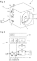
- the invention uses a device 1 for winding watches, especially mechanical or electronic mechanical energy source, comprising at least a support 2 for receiving a watch in a winding position, at least one source of energy 3 arranged to supply energy to at least one motor 4.
- This engine 4 is designed to either drive the winding crown of a manual winding watch, or drive at least one oscillating weight of a self-winding watch, or stir at least one self-winding watch.
- the device 1 comprises control means 100 which comprise measuring means 10 integrating sensor means 20 for vibratory and / or acoustic and / or magnetic measurement of the oscillator of at least one watch placed in the position winding.
- control means 100 are arranged to analyze signals transmitted by the vibratory measurement means and / or acoustic and / or magnetic 10, and compare them to parameterizable setpoints, to regulate the operation of at least one such motor 4 , by switching on this motor 4 when the amplitude of operation of the oscillator is less than or equal to a first minimum value, and stopping this motor 4 when the amplitude of operation of the oscillator is greater than or equal to a second value Max. It is the same for the electromagnetic field of a generator driven by the mechanical energy available.
- the magnetic measuring means are well suited for winding watches whose operation is poorly audible, particularly in the case of watches with non-contact or attenuated exhaust mechanisms, with movement transmission by influence, magnetic and / or electrostatic, or comprising wheels or / and anchors or generally mobiles equipped with flexible blades at their interfaces with antagonistic components.
- the invention is usable for any type of oscillator, and in particular, in the case of a mechanical escapement oscillator, as well for a Swiss anchor escapement, as for a coaxial escapement, or other.
- a suitable parameterization is to be made, without departing from the scope of the invention.
- parameterizable setpoints is meant here that these values depend on the watch model, and may be, as the case may be, either previously introduced during the configuration of the winding device and stored in memory, or read directly on the watch model. shows by a suitable reading device.
- These parameterizable setpoints can, again, be modified and forced by the user, when the device 1 is equipped with a user interface 110 with input-output allowing the modification of these parameterizable values.
- the control means 100 comprise, for example, calculation means 150, such as a microprocessor or the like, for processing the information coming from the sensors, the measurement means 10, a user interface 110 detailed below, from the sources of energy 3 (the figure 2 illustrates, at the level of the control means 100, the inputs 102A and 102B for the communication of the energy level of the energy sources 3), and to give the appropriate commands to the motor 4 or to the motors 4 when there are several.
- calculation means 150 such as a microprocessor or the like, for processing the information coming from the sensors, the measurement means 10, a user interface 110 detailed below, from the sources of energy 3 (the figure 2 illustrates, at the level of the control means 100, the inputs 102A and 102B for the communication of the energy level of the energy sources 3), and to give the appropriate commands to the motor 4 or to the motors 4 when there are several.
- the device 1 can be dedicated to reassembling a single watch, as visible on the figures 1 and 5 .
- each motor 4 is assigned to the reassembly of a particular group consisting of one or more supports 2, each adapted to receive a single watch.
- Each support 2 comprises dedicated sensor means 20.
- the control means 100 are arranged to control each motor 4 as a function of the signals received from the sensor means 20 associated with the different supports 2 of the particular group.
- the figure 2 represents a variant comprising two motors 4A and 4B each driving a support 2A, 2B, arranged to receive a watch 200A, 200B for its reassembly. These motors 4A, 4B are powered by the energy source or sources 3.
- Each support 2A, 2B carries a sensor 20A, 20B, in particular a microphone in an advantageous application, the signal of which is transmitted to the measuring means 10.
- the figure 3 represents schematically and in perspective, another variant comprising two motors 4A, 4B, each driving a shafted support 2A, 2B, which is arranged to receive a plurality of watches for reassembly: three positions corresponding to 20AX sensors, 20AY , 20AZ for the support 2A, and also on three positions corresponding to 20BX, 20BY, 20BZ sensors for the support 2B.
- control means 100 are arranged to differentially control each of the motors 4, as visible in FIG. figure 2 by outputs 101A and 101B for respectively controlling the motors 4A and 4B.
- control means 100 are arranged to control the engine 4 assigned to said particular group by engaging it as soon as the amplitude of operation of any of said oscillators watches worn by the supports 2 of the particular group is less than or equal to a first minimum value.
- control means 100 are arranged to control the engine 4 assigned to such a particular group, stopping it as soon as the amplitude of operation of all the oscillators of the watches carried by the supports 2 of the particular group is greater than or equal to a second maximum value.
- control means 100 are arranged to control the engine 4 assigned to such a particular group, stopping it as soon as the amplitude of operation of any of the oscillators of the watches carried by the supports 2 the particular group is greater than or equal to a second maximum value.
- the figure 5 illustrates a setting of first minimum value and second maximum value for single medium 2.
- the figure 2 illustrates a setting of first minimum value and second maximum value for each of the supports 2A and 2B.
- the figure 3 illustrates a single setting of first minimum value and second maximum value for each of the supports 2A and 2B.
- the figure 4 illustrates a differentiated setting of the first minimum value and the second maximum value for each of the watch receiving positions that comprise the supports 2A and 2B.
- control algorithm can be arranged to activate only one, or only part, of these motor means, especially if the energy level of energy sources 3 is low.
- control means 100 advantageously comprise a user interface 110, which is arranged to allow the user to choose or / and modify the first minimum value and / or the second maximum value for at least one support 2 particular, depending on the watch that receives this support.
- the figures illustrate, in a nonlimiting manner, different inputs of the user interface 110: a socket 111 for connection to a network or a computer or electronic device, an antenna 112 for receiving data by wireless transmission, selectors 113 or 114.
- selectors 113, 114 are analogically shown for the convenience of the figures, they may of course consist of a screen-keyboard assembly or the like.
- a first selector 113A determines the first minimum amplitude value
- a second selector 114A determines the second maximum value.
- this user interface 110 is arranged to allow the user to choose or / and modify the first minimum value and / or the second maximum value for each said particular support 2.
- this user interface 110 is arranged to collect data specific to the first minimum value and / or the second maximum value for a particular type of watch, including but not limited to computer link or wireless communication.
- the user interface 110 comprises reading means 120, which are arranged at the level of at least one support 2, and which are arranged to search and read the parameters of the first minimum value and / or the second maximum value. stored in a watch at a communication interface that includes the watch, for example an RFID chip or the like. More particularly, each support 2 is equipped with such reading means 120.
- control means 100 are then arranged to adjust, for such a support 2 given comprising said reading means 120, the parameters of first minimum value and / or second maximum value read by reading means 120.
- At least one support 2 comprises detection means 130 for the presence or absence of a watch, for example of the optical or capacitive or galvanic type, which are arranged to communicate to the control means 100 the information presence or absence of a watch in order to annihilate the effect of a signal corresponding to zero amplitude in the absence of a watch on the support 2. More particularly, all the supports 2 are thus equipped. This detection allows the standby of the corresponding equipment.
- the figure 2 illustrates, at the level of the control means 100, entries 103A and 103B for the communication of the presence or absence of a watch parameter.
- the angular difference between the first minimum value and / or the second maximum amplitude value is advantageously chosen less than or equal to 20 °.
- the first minimum amplitude value is 240 ° and the second maximum amplitude value is 260 °.
- control means 100 advantageously comprise, at the level of the calculation means 150, timing means 140, which make it possible to determine the time periods at which a watch can be reassembled, and those where it must remain stationary, plus particularly in an indexing position.
- the user interface 110 advantageously includes timer inputs 115 enabling the user to easily determine these time slots.
- the calculation means 150 then immobilize the motor (s) 4 in an indexing position that corresponds to a predefined indexing position of the watch or watches.
- the invention also applies to the use of a watch assembly 1000 comprising such a device 1, and at least one watch 200, mechanical or electronic source of mechanical energy, which is arranged to be fixed on at least one 2.
- the watch 200 comprises a communication interface which is arranged to communicate the first minimum value and / or the second maximum value specific to the watch 200.
- the sensor means 20 may in particular be of the microphone type.
- the principle of an acoustic measurement works well, is reliable, and can retrieve information of duration between the tick and the tac, to calculate the amplitude of the pendulum.
- the winding device can be paired with a particular watch, and preconfigured at the factory.
- the adjustment by the user as presented above allows the user to select on the device a configuration among standard configurations proposed by selectors at the device for the adjustment of amplitude thresholds.
- the user can also use a mobile application, allowing him to choose the product-watch, and send by wireless communication, or computer, or other, the corresponding configuration.
- the watch itself may include a chip with its parameters, or its packaging include a graphic code or a chip, readable by a suitable reader.
- the invention relates to the use of such a device 1 for the reassembly of at least one electronic watch comprising a generator with a source of mechanical energy; its control means 100 then comprise measuring means 10 which incorporate sensor means 20 adapted for measuring the field produced by this generator to control the regulation of the energy recharge.
- Another variant relates to the use of such a device 1 for reassembly of at least one watch comprising a magnetic exhaust mechanism; its control means 100 then comprise measuring means 10 integrating sensor means 20 for measuring the magnetic field to control the regulation of the energy recharge.
Landscapes
- Physics & Mathematics (AREA)
- General Physics & Mathematics (AREA)
- Life Sciences & Earth Sciences (AREA)
- Sustainable Development (AREA)
- Electromechanical Clocks (AREA)
Claims (16)
- Verwendung einer Vorrichtung (1) zum Aufziehen von Uhren, insbesondere zum Aufziehen mindestens einer elektronischen Uhr, umfassend einen Generator für eine mechanische Energiequelle, die mindestens eine Halterung (2) für die Aufnahme einer Uhr in einer Aufziehposition umfasst, und mindestens eine Energiequelle (3), die dafür ausgelegt ist, mindestens einen Motor (4) mit Energie zu versorgen, der dafür ausgelegt ist, entweder die Aufziehkrone einer Uhr mit manuellem Aufzug anzutreiben oder mindestens eine Schwingmasse einer Uhr mit automatischem Aufzug anzutreiben oder mindestens eine Uhr mit automatischem Aufzug zu bewegen, wobei die Vorrichtung (1) Steuermittel (100) umfasst, die Messmittel (10) enthalten, in die Sensormittel (20) integriert sind für die Schwingungs- und/oder akustische und/oder magnetische Messung des Oszillators der mindestens einen in der Aufziehposition angeordneten elektronischen Uhr, wobei die Steuermittel (100) dafür ausgelegt sind, von den Mitteln für die Schwingungs- und/oder akustische und/oder magnetische Messung (10) gesendete Signale zu analysieren und sie mit einstellbaren Sollwerten zu vergleichen, um den Gang mindestens eines Motors (4) zu regulieren, indem sie den Motor (4) einschalten, wenn die Gangamplitude des Oszillators kleiner oder gleich einem ersten Minimalwert ist, und indem sie den Motor (4) anhalten, wenn die Gangamplitude des Oszillators größer oder gleich einem zweiten Maximalwert ist, dadurch gekennzeichnet, dass die Steuermittel (100) Messmittel (10) umfassen, in die Sensormittel (20) für die Messung des im Generator erzeugten Feldes integriert sind, um die Regulierung des Wiederaufladens mit Energie zu steuern.
- Verwendung nach Anspruch 1, dadurch gekennzeichnet, dass jeder Motor (4) dem Aufziehen einer bestimmten Gruppe zugewiesen ist, die aus mehreren Halterungen (2) gebildet ist, jeweils geeignet, eine einzige Uhr aufzunehmen, dass jede Halterung (2) dafür vorgesehene Sensormittel (20) aufweist und dass die Steuermittel (100) dafür ausgelegt sind, jeden Motor (4) in Abhängigkeit von Signalen zu steuern, die von den den Halterungen (2) der bestimmten Gruppe zugeordneten Sensormitteln (20) empfangen werden.
- Verwendung nach Anspruch 2, dadurch gekennzeichnet, dass die Steuermittel (100) dafür ausgelegt sind, jeden der Motoren (4) auf unterschiedliche Weise zu steuern.
- Verwendung nach Anspruch 2 oder 3, dadurch gekennzeichnet, dass die Steuermittel (100) dafür ausgelegt sind, den der bestimmten Gruppe zugewiesenen Motor (4) bei seinem Einschalten zu steuern, sobald die Gangamplitude eines beliebigen der Oszillatoren der Uhren, die von den Halterungen (2) der bestimmten Gruppe getragen werden, kleiner oder gleich einem ersten Minimalwert ist.
- Verwendung nach Anspruch 4, dadurch gekennzeichnet, dass die Steuermittel (100) dafür ausgelegt sind, den der bestimmten Gruppe zugewiesenen Motor (4) bei seinem Anhalten zu steuern, sobald die Gangamplitude aller Oszillatoren der Uhren, die von den Halterungen (2) der bestimmten Gruppe getragen werden, größer oder gleich einem zweiten Maximalwert ist.
- Verwendung nach Anspruch 4, dadurch gekennzeichnet, dass die Steuermittel (100) dafür ausgelegt sind, den der bestimmten Gruppe zugewiesenen Motor (4) bei seinem Anhalten zu steuern, sobald die Gangamplitude eines Beliebigen der Oszillatoren der Uhren, die von den Halterungen (2) der bestimmten Gruppe getragen werden, größer oder gleich einem zweiten Maximalwert ist.
- Verwendung nach einem der Ansprüche 1 bis 6, dadurch gekennzeichnet, dass die Steuermittel (100) eine Anwenderschnittstelle (110) umfassen, die dafür ausgelegt ist, dem Anwender zu ermöglichen, den ersten Minimalwert und/oder den zweiten Maximalwert für mindestens eine bestimmte Halterung (2) zu wählen und/oder zu verändern.
- Verwendung nach Anspruch 7, dadurch gekennzeichnet, dass die Anwenderschnittstelle (110) dafür ausgelegt ist, dem Anwender zu ermöglichen, den ersten Minimalwert und/oder den zweiten Maximalwert für jede bestimmte Halterung (2) zu wählen und/oder zu verändern.
- Verwendung nach Anspruch 7 oder 8, dadurch gekennzeichnet, dass die Anwenderschnittstelle (110) dafür ausgelegt ist, Daten, die dem ersten Minimalwert und/oder dem zweiten Maximalwert für einen bestimmten Uhrentyp eigen sind, über eine computergestützte Verbindung oder durch drahtlose Kommunikation zu sammeln.
- Verwendung nach Anspruch 9, dadurch gekennzeichnet, dass die Anwenderschnittstelle (110) Lesemittel (120) umfasst, die auf Seiten mindestens einer Halterung (2) angeordnet sind und dafür ausgelegt sind, die Parameter des ersten Minimalwerts und/oder des zweiten Maximalwerts zu suchen und zu lesen, die in einer Uhr auf Seiten einer Kommunikationsschnittstelle, die die Uhr aufweist, gespeichert sind.
- Verwendung nach Anspruch 10, dadurch gekennzeichnet, dass die Steuermittel (100) dafür ausgelegt sind, die Parameter des ersten Minimalwerts und/oder des zweiten Maximalwerts, die von den Lesemitteln (120) abgelesen werden, für eine bestimmte Halterung (2), die die Lesemittel (120) umfasst, einzustellen.
- Verwendung nach einem der Ansprüche 1 bis 11, dadurch gekennzeichnet, dass mindestens eine Halterung (2) Mittel (130) zum Detektieren des Vorhandenseins oder Fehlens einer Uhr umfasst, die dafür ausgelegt sind, den Steuermitteln (100) Informationen über das Vorhandensein oder Fehlen einer Uhr zu kommunizieren, um die Wirkung eines Signals, das einer Null-Amplitude entspricht, im Fall des Fehlens einer Uhr auf der Halterung (2) zu unterdrücken.
- Verwendung nach einem der Ansprüche 1 bis 12, dadurch gekennzeichnet, dass der Winkelabstand zwischen dem ersten Minimalwert und/oder dem zweiten Maximalwert der Amplitude kleiner oder gleich 20° ist.
- Verwendung nach einem der Ansprüche 1 bis 13, dadurch gekennzeichnet, dass der erste Minimalwert der Amplitude 240° beträgt und der zweite Maximalwert der Amplitude 260° beträgt.
- Verwendung nach einem der Ansprüche 1 bis 14, dadurch gekennzeichnet, dass die Steuermittel (100) Zeitbestimmungsmittel (140) umfassen, die ermöglichen, die Zeitbereiche, in denen eine Uhr aufgezogen werden kann, und jene in denen sie in einer Indexierungsposition unbeweglich bleiben soll, zu bestimmen.
- Verwendung nach den Ansprüchen 7 und 15, dadurch gekennzeichnet, dass die Anwenderschnittstelle (110) Zeitbestimmungseingänge (115) umfasst, ausgelegt, die Bestimmung der Zeitbereiche für den Benutzer so zu ermöglichen, dass diese Zeitbereiche einfach bestimmt werden können.
Priority Applications (3)
| Application Number | Priority Date | Filing Date | Title |
|---|---|---|---|
| CH00679/15A CH711099B1 (fr) | 2015-05-18 | 2015-05-18 | Dispositif de remontage de montres. |
| EP15167923.0A EP3096191B1 (de) | 2015-05-18 | 2015-05-18 | Intelligente vorrichtung zum aufziehen von armbanduhren |
| PCT/EP2016/060495 WO2016184736A1 (fr) | 2015-05-18 | 2016-05-11 | Dispositif intelligent de remontage de montres |
Applications Claiming Priority (2)
| Application Number | Priority Date | Filing Date | Title |
|---|---|---|---|
| CH00679/15A CH711099B1 (fr) | 2015-05-18 | 2015-05-18 | Dispositif de remontage de montres. |
| EP15167923.0A EP3096191B1 (de) | 2015-05-18 | 2015-05-18 | Intelligente vorrichtung zum aufziehen von armbanduhren |
Publications (2)
| Publication Number | Publication Date |
|---|---|
| EP3096191A1 EP3096191A1 (de) | 2016-11-23 |
| EP3096191B1 true EP3096191B1 (de) | 2018-11-14 |
Family
ID=53181129
Family Applications (1)
| Application Number | Title | Priority Date | Filing Date |
|---|---|---|---|
| EP15167923.0A Active EP3096191B1 (de) | 2015-05-18 | 2015-05-18 | Intelligente vorrichtung zum aufziehen von armbanduhren |
Country Status (3)
| Country | Link |
|---|---|
| EP (1) | EP3096191B1 (de) |
| CH (1) | CH711099B1 (de) |
| WO (1) | WO2016184736A1 (de) |
Cited By (1)
| Publication number | Priority date | Publication date | Assignee | Title |
|---|---|---|---|---|
| US11669050B2 (en) | 2019-12-12 | 2023-06-06 | The Swatch Group Research And Development Ltd | Watch self-winding device with rotary motion |
Families Citing this family (15)
| Publication number | Priority date | Publication date | Assignee | Title |
|---|---|---|---|---|
| CH713271A2 (fr) * | 2016-12-22 | 2018-06-29 | Swatch Group Res & Dev Ltd | Dispositif intelligent de remontage de montres. |
| EP3474086A1 (de) * | 2017-10-23 | 2019-04-24 | Harry Winston SA | Etui für elektromechanische armbanduhr, und dieses umfassende einheit |
| EP3502799A1 (de) | 2017-12-22 | 2019-06-26 | The Swatch Group Research and Development Ltd | Aufladevorrichtung einer elektronischen oder elektromechanischen armbanduhr, und diese umfassende einheit |
| EP3511781B1 (de) * | 2018-01-12 | 2020-08-26 | Richemont International S.A. | Vorrichtung und verfahren zur erhebung, speicherung, auswertung sowie zugänglichmachung der auswerteergebnisse von daten von uhren |
| EP3537233A1 (de) * | 2018-03-08 | 2019-09-11 | IAV Engineering SARL | Zeiteinstellungsvorrichtung |
| EP3719589B1 (de) * | 2018-05-21 | 2025-01-01 | The Swatch Group Research and Development Ltd | Universalvorrichtung zum aufziehen und stellen einer armbanduhr |
| CN109343324B (zh) * | 2018-10-23 | 2020-11-03 | 苏州边际智能科技有限公司 | 手表防磁性能检测设备 |
| CN112711186A (zh) * | 2019-04-27 | 2021-04-27 | 林清贵 | 一种手表防磁性能检测系统及使用方法 |
| CN113835327B (zh) * | 2020-06-23 | 2024-09-27 | 天津海鸥表业集团有限公司 | 一种手表走时精度检测装置及检测方法 |
| EP3982209B1 (de) | 2020-10-06 | 2023-06-07 | The Swatch Group Research and Development Ltd | Vorrichtung zur spannungsbegrenzung eines federhauses einer uhr |
| EP3985454B1 (de) * | 2020-10-14 | 2023-03-29 | The Swatch Group Research and Development Ltd | Aufziehvorrichtung für automatische armbanduhr |
| CN112363375A (zh) * | 2020-11-11 | 2021-02-12 | 天王电子(深圳)有限公司 | 一种智能陀飞轮手表 |
| EP4002018B1 (de) | 2020-11-12 | 2026-02-25 | The Swatch Group Research and Development Ltd | Intelligente aufziehvorrichtung einer automatischen armbanduhr mit armbanduhridentifikation |
| CN117492347B (zh) * | 2023-12-12 | 2026-04-10 | 深圳西普尼精密科技股份有限公司 | 自动上弦机芯的动能回收装置 |
| WO2026022020A1 (fr) * | 2024-07-24 | 2026-01-29 | Rolex Sa | Dispositif de contrôle d'une pièce d'horlogerie |
Family Cites Families (14)
| Publication number | Priority date | Publication date | Assignee | Title |
|---|---|---|---|---|
| US2638024A (en) * | 1951-09-28 | 1953-05-12 | John H Gotter | Watch winding machine |
| CH535452A (de) * | 1971-06-03 | 1972-12-15 | Greiner Electronic Ag | Verfahren zur Bestimmung einer Bewegungsgrösse, insbesondere des Abfallfehlers, des Gangreglers von Uhrwerken |
| SU1190353A1 (ru) * | 1984-06-28 | 1985-11-07 | Центральный Научно-Исследовательский Институт Бытового Обслуживания "Цниибыт" | Устройство дл контрол электронных блоков электронно-механических часов |
| DE10338932B4 (de) * | 2003-08-21 | 2009-10-15 | Elma Hans Schmidbauer Gmbh & Co. Kg | Verfahren zum automatischen Aufziehen einer Uhr |
| JP2005098938A (ja) * | 2003-09-26 | 2005-04-14 | Seiko Epson Corp | 巻上げ装置 |
| US20070159929A1 (en) * | 2006-01-06 | 2007-07-12 | Louie Lip M | Watch-winding apparatus |
| DE202008003821U1 (de) * | 2008-03-18 | 2008-05-29 | Lunz, Michael | Uhrenbeweger mit bidirektionalem Funkmodul |
| EP2345940A1 (de) * | 2010-01-13 | 2011-07-20 | MCM Milano S.R.L. | Vorrichtung zum Aufziehen von Uhren, insbesondere automatischen Uhren |
| DE202010005873U1 (de) * | 2010-04-14 | 2010-09-30 | Mte Bewegungstechnik Gmbh & Co. Kg | Uhrenbewegereinrichtung |
| CH704693B1 (fr) * | 2010-07-16 | 2015-08-14 | Eta Sa Manufacture Horlogère Suisse | Procédé d'ajustement de fréquence d'oscillation, et/ou d'ajustement d'inertie, et/ou d'équilibrage d'un composant mobile de mouvement d'horlogerie, ou d'un ensemble balancier-spiral d'horlogerie. |
| CH704992B1 (fr) * | 2011-05-23 | 2017-06-30 | Queloz Pascal | Procédé de détermination du taux de remontage d'une montre mécanique et de remontage automatique et dispositif pour la mise en œuvre du procédé. |
| EP2650734B1 (de) | 2012-04-13 | 2018-01-24 | ETA SA Manufacture Horlogère Suisse | Batteriebefestigung mit verbessertem Kontakt |
| EP2746869B1 (de) * | 2012-12-21 | 2019-10-16 | The Swatch Group Research and Development Ltd. | Elektrischer Solar-Aufzugmechanismus für automatische Armbanduhr |
| DE102014103797B4 (de) * | 2014-03-20 | 2020-09-17 | Designhütte GmbH | Vorrichtung zum Steuern von Rotationseinheiten in Mehrfach-Uhrenbewegern |
-
2015
- 2015-05-18 EP EP15167923.0A patent/EP3096191B1/de active Active
- 2015-05-18 CH CH00679/15A patent/CH711099B1/fr unknown
-
2016
- 2016-05-11 WO PCT/EP2016/060495 patent/WO2016184736A1/fr not_active Ceased
Non-Patent Citations (1)
| Title |
|---|
| None * |
Cited By (1)
| Publication number | Priority date | Publication date | Assignee | Title |
|---|---|---|---|---|
| US11669050B2 (en) | 2019-12-12 | 2023-06-06 | The Swatch Group Research And Development Ltd | Watch self-winding device with rotary motion |
Also Published As
| Publication number | Publication date |
|---|---|
| CH711099A2 (fr) | 2016-11-30 |
| CH711099B1 (fr) | 2019-08-15 |
| WO2016184736A1 (fr) | 2016-11-24 |
| EP3096191A1 (de) | 2016-11-23 |
Similar Documents
| Publication | Publication Date | Title |
|---|---|---|
| EP3339984B1 (de) | Intelligente vorrichtung zum aufziehen von armbanduhren | |
| EP3096191A1 (de) | Intelligente vorrichtung zum aufziehen von armbanduhren | |
| EP2689293A1 (de) | Multifunktionsgehäuse | |
| WO2014207220A2 (fr) | Dispositif portatif multifonctions contrôlé par information externe | |
| EP3379347B1 (de) | Verfahren zur regulierung der gangfrequenz einer elektronischen uhr | |
| EP2021822A1 (de) | Luftnavigationseinrichtung mit trägheitssensoreinheiten, funknavigationsempfänger und solche elemente verwendende funknavigationstechnik | |
| EP1723477A1 (de) | Mit analoganzeige-variometerfunktion ausgestattete tragbare elektronische einrichtung | |
| EP3683633B1 (de) | Uhr mit mechanischem oszillator, die ein drahtloses kommunikationsmodul umfasst | |
| EP4002018B1 (de) | Intelligente aufziehvorrichtung einer automatischen armbanduhr mit armbanduhridentifikation | |
| EP3839665B1 (de) | Einstellverfahren einer elektronischen uhr | |
| CH711303A1 (fr) | Dispositif de correction pour un mouvement horloger mécanique. | |
| EP0476425B1 (de) | Eine auf verschiedene Arten zu tragende Uhr | |
| WO2017114759A1 (fr) | Procédé de commande d'un système ophtalmique à partir d'une mesure et d'une information obtenue par un dispositif électronique externe | |
| EP4092494A1 (de) | Einstellsystem einer armbanduhr | |
| FR2945868A1 (fr) | Procede et dispositif d'integration d'un emulateur rf gps dans un environnement de simulation | |
| EP0660205A1 (de) | Verfahren zur Ortsbestimmung und Uhr zur Ausführung dieses Verfahrens | |
| EP3827342B1 (de) | Verfahren zum korrigieren von daten zwischen zwei periodischen prozessen und automatisches system zur durchführung des verfahrens | |
| EP3454140B1 (de) | Astronomische uhrvorrichtung | |
| EP3985446A1 (de) | Vorrichtung zur positionsbestimmung einer uhranzeige | |
| CH718047A2 (fr) | Remontoir intelligent de montre automatique avec identification de montre. | |
| EP4459388A1 (de) | Tragbares objekt, insbesondere uhr, mit einer vorrichtung zur detektion des durchgangs der karman-linie, und detektionsverfahren | |
| EP4095623A1 (de) | Vorrichtung zum aufziehen oder einstellen und kontrollieren einer armbanduhr | |
| FR3139207A1 (fr) | Ecrin pour pièce d’horlogerie. | |
| CH716962A2 (fr) | Procédé de réglage d'une montre électronique. | |
| CH719993A2 (fr) | Dispositif de mise à l'heure pour pièce d'horlogerie, notamment sous la forme d'un écrin. |
Legal Events
| Date | Code | Title | Description |
|---|---|---|---|
| PUAI | Public reference made under article 153(3) epc to a published international application that has entered the european phase |
Free format text: ORIGINAL CODE: 0009012 |
|
| AK | Designated contracting states |
Kind code of ref document: A1 Designated state(s): AL AT BE BG CH CY CZ DE DK EE ES FI FR GB GR HR HU IE IS IT LI LT LU LV MC MK MT NL NO PL PT RO RS SE SI SK SM TR |
|
| AX | Request for extension of the european patent |
Extension state: BA ME |
|
| STAA | Information on the status of an ep patent application or granted ep patent |
Free format text: STATUS: REQUEST FOR EXAMINATION WAS MADE |
|
| 17P | Request for examination filed |
Effective date: 20170523 |
|
| RBV | Designated contracting states (corrected) |
Designated state(s): AL AT BE BG CH CY CZ DE DK EE ES FI FR GB GR HR HU IE IS IT LI LT LU LV MC MK MT NL NO PL PT RO RS SE SI SK SM TR |
|
| GRAP | Despatch of communication of intention to grant a patent |
Free format text: ORIGINAL CODE: EPIDOSNIGR1 |
|
| STAA | Information on the status of an ep patent application or granted ep patent |
Free format text: STATUS: GRANT OF PATENT IS INTENDED |
|
| INTG | Intention to grant announced |
Effective date: 20180615 |
|
| GRAS | Grant fee paid |
Free format text: ORIGINAL CODE: EPIDOSNIGR3 |
|
| GRAA | (expected) grant |
Free format text: ORIGINAL CODE: 0009210 |
|
| STAA | Information on the status of an ep patent application or granted ep patent |
Free format text: STATUS: THE PATENT HAS BEEN GRANTED |
|
| AK | Designated contracting states |
Kind code of ref document: B1 Designated state(s): AL AT BE BG CH CY CZ DE DK EE ES FI FR GB GR HR HU IE IS IT LI LT LU LV MC MK MT NL NO PL PT RO RS SE SI SK SM TR |
|
| REG | Reference to a national code |
Ref country code: CH Ref legal event code: EP Ref country code: AT Ref legal event code: REF Ref document number: 1065553 Country of ref document: AT Kind code of ref document: T Effective date: 20181115 |
|
| REG | Reference to a national code |
Ref country code: DE Ref legal event code: R096 Ref document number: 602015019714 Country of ref document: DE |
|
| REG | Reference to a national code |
Ref country code: IE Ref legal event code: FG4D Free format text: LANGUAGE OF EP DOCUMENT: FRENCH |
|
| REG | Reference to a national code |
Ref country code: NL Ref legal event code: MP Effective date: 20181114 |
|
| REG | Reference to a national code |
Ref country code: LT Ref legal event code: MG4D |
|
| REG | Reference to a national code |
Ref country code: AT Ref legal event code: MK05 Ref document number: 1065553 Country of ref document: AT Kind code of ref document: T Effective date: 20181114 |
|
| PG25 | Lapsed in a contracting state [announced via postgrant information from national office to epo] |
Ref country code: LV Free format text: LAPSE BECAUSE OF FAILURE TO SUBMIT A TRANSLATION OF THE DESCRIPTION OR TO PAY THE FEE WITHIN THE PRESCRIBED TIME-LIMIT Effective date: 20181114 Ref country code: HR Free format text: LAPSE BECAUSE OF FAILURE TO SUBMIT A TRANSLATION OF THE DESCRIPTION OR TO PAY THE FEE WITHIN THE PRESCRIBED TIME-LIMIT Effective date: 20181114 Ref country code: AT Free format text: LAPSE BECAUSE OF FAILURE TO SUBMIT A TRANSLATION OF THE DESCRIPTION OR TO PAY THE FEE WITHIN THE PRESCRIBED TIME-LIMIT Effective date: 20181114 Ref country code: BG Free format text: LAPSE BECAUSE OF FAILURE TO SUBMIT A TRANSLATION OF THE DESCRIPTION OR TO PAY THE FEE WITHIN THE PRESCRIBED TIME-LIMIT Effective date: 20190214 Ref country code: LT Free format text: LAPSE BECAUSE OF FAILURE TO SUBMIT A TRANSLATION OF THE DESCRIPTION OR TO PAY THE FEE WITHIN THE PRESCRIBED TIME-LIMIT Effective date: 20181114 Ref country code: NO Free format text: LAPSE BECAUSE OF FAILURE TO SUBMIT A TRANSLATION OF THE DESCRIPTION OR TO PAY THE FEE WITHIN THE PRESCRIBED TIME-LIMIT Effective date: 20190214 Ref country code: ES Free format text: LAPSE BECAUSE OF FAILURE TO SUBMIT A TRANSLATION OF THE DESCRIPTION OR TO PAY THE FEE WITHIN THE PRESCRIBED TIME-LIMIT Effective date: 20181114 Ref country code: IS Free format text: LAPSE BECAUSE OF FAILURE TO SUBMIT A TRANSLATION OF THE DESCRIPTION OR TO PAY THE FEE WITHIN THE PRESCRIBED TIME-LIMIT Effective date: 20190314 Ref country code: FI Free format text: LAPSE BECAUSE OF FAILURE TO SUBMIT A TRANSLATION OF THE DESCRIPTION OR TO PAY THE FEE WITHIN THE PRESCRIBED TIME-LIMIT Effective date: 20181114 |
|
| PG25 | Lapsed in a contracting state [announced via postgrant information from national office to epo] |
Ref country code: GR Free format text: LAPSE BECAUSE OF FAILURE TO SUBMIT A TRANSLATION OF THE DESCRIPTION OR TO PAY THE FEE WITHIN THE PRESCRIBED TIME-LIMIT Effective date: 20190215 Ref country code: RS Free format text: LAPSE BECAUSE OF FAILURE TO SUBMIT A TRANSLATION OF THE DESCRIPTION OR TO PAY THE FEE WITHIN THE PRESCRIBED TIME-LIMIT Effective date: 20181114 Ref country code: SE Free format text: LAPSE BECAUSE OF FAILURE TO SUBMIT A TRANSLATION OF THE DESCRIPTION OR TO PAY THE FEE WITHIN THE PRESCRIBED TIME-LIMIT Effective date: 20181114 Ref country code: AL Free format text: LAPSE BECAUSE OF FAILURE TO SUBMIT A TRANSLATION OF THE DESCRIPTION OR TO PAY THE FEE WITHIN THE PRESCRIBED TIME-LIMIT Effective date: 20181114 Ref country code: PT Free format text: LAPSE BECAUSE OF FAILURE TO SUBMIT A TRANSLATION OF THE DESCRIPTION OR TO PAY THE FEE WITHIN THE PRESCRIBED TIME-LIMIT Effective date: 20190314 Ref country code: NL Free format text: LAPSE BECAUSE OF FAILURE TO SUBMIT A TRANSLATION OF THE DESCRIPTION OR TO PAY THE FEE WITHIN THE PRESCRIBED TIME-LIMIT Effective date: 20181114 |
|
| PG25 | Lapsed in a contracting state [announced via postgrant information from national office to epo] |
Ref country code: DK Free format text: LAPSE BECAUSE OF FAILURE TO SUBMIT A TRANSLATION OF THE DESCRIPTION OR TO PAY THE FEE WITHIN THE PRESCRIBED TIME-LIMIT Effective date: 20181114 Ref country code: PL Free format text: LAPSE BECAUSE OF FAILURE TO SUBMIT A TRANSLATION OF THE DESCRIPTION OR TO PAY THE FEE WITHIN THE PRESCRIBED TIME-LIMIT Effective date: 20181114 Ref country code: IT Free format text: LAPSE BECAUSE OF FAILURE TO SUBMIT A TRANSLATION OF THE DESCRIPTION OR TO PAY THE FEE WITHIN THE PRESCRIBED TIME-LIMIT Effective date: 20181114 Ref country code: CZ Free format text: LAPSE BECAUSE OF FAILURE TO SUBMIT A TRANSLATION OF THE DESCRIPTION OR TO PAY THE FEE WITHIN THE PRESCRIBED TIME-LIMIT Effective date: 20181114 |
|
| REG | Reference to a national code |
Ref country code: DE Ref legal event code: R097 Ref document number: 602015019714 Country of ref document: DE |
|
| PG25 | Lapsed in a contracting state [announced via postgrant information from national office to epo] |
Ref country code: RO Free format text: LAPSE BECAUSE OF FAILURE TO SUBMIT A TRANSLATION OF THE DESCRIPTION OR TO PAY THE FEE WITHIN THE PRESCRIBED TIME-LIMIT Effective date: 20181114 Ref country code: SM Free format text: LAPSE BECAUSE OF FAILURE TO SUBMIT A TRANSLATION OF THE DESCRIPTION OR TO PAY THE FEE WITHIN THE PRESCRIBED TIME-LIMIT Effective date: 20181114 Ref country code: EE Free format text: LAPSE BECAUSE OF FAILURE TO SUBMIT A TRANSLATION OF THE DESCRIPTION OR TO PAY THE FEE WITHIN THE PRESCRIBED TIME-LIMIT Effective date: 20181114 Ref country code: SK Free format text: LAPSE BECAUSE OF FAILURE TO SUBMIT A TRANSLATION OF THE DESCRIPTION OR TO PAY THE FEE WITHIN THE PRESCRIBED TIME-LIMIT Effective date: 20181114 |
|
| PLBE | No opposition filed within time limit |
Free format text: ORIGINAL CODE: 0009261 |
|
| STAA | Information on the status of an ep patent application or granted ep patent |
Free format text: STATUS: NO OPPOSITION FILED WITHIN TIME LIMIT |
|
| 26N | No opposition filed |
Effective date: 20190815 |
|
| PG25 | Lapsed in a contracting state [announced via postgrant information from national office to epo] |
Ref country code: SI Free format text: LAPSE BECAUSE OF FAILURE TO SUBMIT A TRANSLATION OF THE DESCRIPTION OR TO PAY THE FEE WITHIN THE PRESCRIBED TIME-LIMIT Effective date: 20181114 |
|
| GBPC | Gb: european patent ceased through non-payment of renewal fee |
Effective date: 20190518 |
|
| PG25 | Lapsed in a contracting state [announced via postgrant information from national office to epo] |
Ref country code: MC Free format text: LAPSE BECAUSE OF FAILURE TO SUBMIT A TRANSLATION OF THE DESCRIPTION OR TO PAY THE FEE WITHIN THE PRESCRIBED TIME-LIMIT Effective date: 20181114 |
|
| REG | Reference to a national code |
Ref country code: BE Ref legal event code: MM Effective date: 20190531 |
|
| PG25 | Lapsed in a contracting state [announced via postgrant information from national office to epo] |
Ref country code: LU Free format text: LAPSE BECAUSE OF NON-PAYMENT OF DUE FEES Effective date: 20190518 |
|
| PG25 | Lapsed in a contracting state [announced via postgrant information from national office to epo] |
Ref country code: TR Free format text: LAPSE BECAUSE OF FAILURE TO SUBMIT A TRANSLATION OF THE DESCRIPTION OR TO PAY THE FEE WITHIN THE PRESCRIBED TIME-LIMIT Effective date: 20181114 |
|
| PG25 | Lapsed in a contracting state [announced via postgrant information from national office to epo] |
Ref country code: IE Free format text: LAPSE BECAUSE OF NON-PAYMENT OF DUE FEES Effective date: 20190518 Ref country code: GB Free format text: LAPSE BECAUSE OF NON-PAYMENT OF DUE FEES Effective date: 20190518 |
|
| PG25 | Lapsed in a contracting state [announced via postgrant information from national office to epo] |
Ref country code: BE Free format text: LAPSE BECAUSE OF NON-PAYMENT OF DUE FEES Effective date: 20190531 |
|
| PG25 | Lapsed in a contracting state [announced via postgrant information from national office to epo] |
Ref country code: CY Free format text: LAPSE BECAUSE OF FAILURE TO SUBMIT A TRANSLATION OF THE DESCRIPTION OR TO PAY THE FEE WITHIN THE PRESCRIBED TIME-LIMIT Effective date: 20181114 |
|
| PG25 | Lapsed in a contracting state [announced via postgrant information from national office to epo] |
Ref country code: MT Free format text: LAPSE BECAUSE OF FAILURE TO SUBMIT A TRANSLATION OF THE DESCRIPTION OR TO PAY THE FEE WITHIN THE PRESCRIBED TIME-LIMIT Effective date: 20181114 Ref country code: HU Free format text: LAPSE BECAUSE OF FAILURE TO SUBMIT A TRANSLATION OF THE DESCRIPTION OR TO PAY THE FEE WITHIN THE PRESCRIBED TIME-LIMIT; INVALID AB INITIO Effective date: 20150518 |
|
| PG25 | Lapsed in a contracting state [announced via postgrant information from national office to epo] |
Ref country code: MK Free format text: LAPSE BECAUSE OF FAILURE TO SUBMIT A TRANSLATION OF THE DESCRIPTION OR TO PAY THE FEE WITHIN THE PRESCRIBED TIME-LIMIT Effective date: 20181114 |
|
| P01 | Opt-out of the competence of the unified patent court (upc) registered |
Effective date: 20230615 |
|
| PGFP | Annual fee paid to national office [announced via postgrant information from national office to epo] |
Ref country code: DE Payment date: 20250423 Year of fee payment: 11 |
|
| PGFP | Annual fee paid to national office [announced via postgrant information from national office to epo] |
Ref country code: FR Payment date: 20250423 Year of fee payment: 11 |
|
| PGFP | Annual fee paid to national office [announced via postgrant information from national office to epo] |
Ref country code: CH Payment date: 20250601 Year of fee payment: 11 |
|
| REG | Reference to a national code |
Ref country code: CH Ref legal event code: R14 Free format text: ST27 STATUS EVENT CODE: U-0-0-R10-R14 (AS PROVIDED BY THE NATIONAL OFFICE) Effective date: 20260417 Ref country code: CH Ref legal event code: R17 Free format text: ST27 STATUS EVENT CODE: U-0-0-R10-R17 (AS PROVIDED BY THE NATIONAL OFFICE) Effective date: 20260417 |