EP3096819B1 - Automatischer injektor - Google Patents
Automatischer injektor Download PDFInfo
- Publication number
- EP3096819B1 EP3096819B1 EP15700691.7A EP15700691A EP3096819B1 EP 3096819 B1 EP3096819 B1 EP 3096819B1 EP 15700691 A EP15700691 A EP 15700691A EP 3096819 B1 EP3096819 B1 EP 3096819B1
- Authority
- EP
- European Patent Office
- Prior art keywords
- injection
- lever
- rod
- piece
- needle
- Prior art date
- Legal status (The legal status is an assumption and is not a legal conclusion. Google has not performed a legal analysis and makes no representation as to the accuracy of the status listed.)
- Active
Links
Images




Classifications
-
- A—HUMAN NECESSITIES
- A61—MEDICAL OR VETERINARY SCIENCE; HYGIENE
- A61M—DEVICES FOR INTRODUCING MEDIA INTO, OR ONTO, THE BODY; DEVICES FOR TRANSDUCING BODY MEDIA OR FOR TAKING MEDIA FROM THE BODY; DEVICES FOR PRODUCING OR ENDING SLEEP OR STUPOR
- A61M5/00—Devices for bringing media into the body in a subcutaneous, intra-vascular or intramuscular way; Accessories therefor, e.g. filling or cleaning devices, arm-rests
- A61M5/178—Syringes
- A61M5/31—Details
- A61M5/315—Pistons; Piston-rods; Guiding, blocking or restricting the movement of the rod or piston; Appliances on the rod for facilitating dosing ; Dosing mechanisms
- A61M5/31565—Administration mechanisms, i.e. constructional features, modes of administering a dose
- A61M5/31566—Means improving security or handling thereof
- A61M5/31571—Means preventing accidental administration
-
- A—HUMAN NECESSITIES
- A61—MEDICAL OR VETERINARY SCIENCE; HYGIENE
- A61M—DEVICES FOR INTRODUCING MEDIA INTO, OR ONTO, THE BODY; DEVICES FOR TRANSDUCING BODY MEDIA OR FOR TAKING MEDIA FROM THE BODY; DEVICES FOR PRODUCING OR ENDING SLEEP OR STUPOR
- A61M5/00—Devices for bringing media into the body in a subcutaneous, intra-vascular or intramuscular way; Accessories therefor, e.g. filling or cleaning devices, arm-rests
- A61M5/178—Syringes
- A61M5/20—Automatic syringes, e.g. with automatically actuated piston rod, with automatic needle injection, filling automatically
-
- A—HUMAN NECESSITIES
- A61—MEDICAL OR VETERINARY SCIENCE; HYGIENE
- A61M—DEVICES FOR INTRODUCING MEDIA INTO, OR ONTO, THE BODY; DEVICES FOR TRANSDUCING BODY MEDIA OR FOR TAKING MEDIA FROM THE BODY; DEVICES FOR PRODUCING OR ENDING SLEEP OR STUPOR
- A61M5/00—Devices for bringing media into the body in a subcutaneous, intra-vascular or intramuscular way; Accessories therefor, e.g. filling or cleaning devices, arm-rests
- A61M5/178—Syringes
- A61M5/20—Automatic syringes, e.g. with automatically actuated piston rod, with automatic needle injection, filling automatically
- A61M5/2033—Spring-loaded one-shot injectors with or without automatic needle insertion
-
- A—HUMAN NECESSITIES
- A61—MEDICAL OR VETERINARY SCIENCE; HYGIENE
- A61M—DEVICES FOR INTRODUCING MEDIA INTO, OR ONTO, THE BODY; DEVICES FOR TRANSDUCING BODY MEDIA OR FOR TAKING MEDIA FROM THE BODY; DEVICES FOR PRODUCING OR ENDING SLEEP OR STUPOR
- A61M5/00—Devices for bringing media into the body in a subcutaneous, intra-vascular or intramuscular way; Accessories therefor, e.g. filling or cleaning devices, arm-rests
- A61M5/178—Syringes
- A61M5/31—Details
- A61M5/32—Needles; Details of needles pertaining to their connection with syringe or hub; Accessories for bringing the needle into, or holding the needle on, the body; Devices for protection of needles
- A61M5/3202—Devices for protection of the needle before use, e.g. caps
- A61M5/3204—Needle cap remover, i.e. devices to dislodge protection cover from needle or needle hub, e.g. deshielding devices
-
- A—HUMAN NECESSITIES
- A61—MEDICAL OR VETERINARY SCIENCE; HYGIENE
- A61M—DEVICES FOR INTRODUCING MEDIA INTO, OR ONTO, THE BODY; DEVICES FOR TRANSDUCING BODY MEDIA OR FOR TAKING MEDIA FROM THE BODY; DEVICES FOR PRODUCING OR ENDING SLEEP OR STUPOR
- A61M5/00—Devices for bringing media into the body in a subcutaneous, intra-vascular or intramuscular way; Accessories therefor, e.g. filling or cleaning devices, arm-rests
- A61M5/178—Syringes
- A61M5/31—Details
- A61M5/32—Needles; Details of needles pertaining to their connection with syringe or hub; Accessories for bringing the needle into, or holding the needle on, the body; Devices for protection of needles
- A61M5/3205—Apparatus for removing or disposing of used needles or syringes, e.g. containers; Means for protection against accidental injuries from used needles
- A61M5/321—Means for protection against accidental injuries by used needles
- A61M5/322—Retractable needles, i.e. disconnected from and withdrawn into the syringe barrel by the piston
- A61M5/3234—Fully automatic needle retraction, i.e. in which triggering of the needle does not require a deliberate action by the user
-
- A—HUMAN NECESSITIES
- A61—MEDICAL OR VETERINARY SCIENCE; HYGIENE
- A61M—DEVICES FOR INTRODUCING MEDIA INTO, OR ONTO, THE BODY; DEVICES FOR TRANSDUCING BODY MEDIA OR FOR TAKING MEDIA FROM THE BODY; DEVICES FOR PRODUCING OR ENDING SLEEP OR STUPOR
- A61M5/00—Devices for bringing media into the body in a subcutaneous, intra-vascular or intramuscular way; Accessories therefor, e.g. filling or cleaning devices, arm-rests
- A61M5/178—Syringes
- A61M5/20—Automatic syringes, e.g. with automatically actuated piston rod, with automatic needle injection, filling automatically
- A61M2005/2026—Semi-automatic, e.g. user activated piston is assisted by additional source of energy
-
- A—HUMAN NECESSITIES
- A61—MEDICAL OR VETERINARY SCIENCE; HYGIENE
- A61M—DEVICES FOR INTRODUCING MEDIA INTO, OR ONTO, THE BODY; DEVICES FOR TRANSDUCING BODY MEDIA OR FOR TAKING MEDIA FROM THE BODY; DEVICES FOR PRODUCING OR ENDING SLEEP OR STUPOR
- A61M5/00—Devices for bringing media into the body in a subcutaneous, intra-vascular or intramuscular way; Accessories therefor, e.g. filling or cleaning devices, arm-rests
- A61M5/178—Syringes
- A61M5/20—Automatic syringes, e.g. with automatically actuated piston rod, with automatic needle injection, filling automatically
- A61M2005/2073—Automatic syringes, e.g. with automatically actuated piston rod, with automatic needle injection, filling automatically preventing premature release, e.g. by making use of a safety lock
- A61M2005/208—Release is possible only when device is pushed against the skin, e.g. using a trigger which is blocked or inactive when the device is not pushed against the skin
Definitions
- the present invention relates to an automatic injector, or auto-injector.
- drugs for emergency treatment are stored in glass syringes equipped with a glued needle, a plunger and a needle guard. These syringes are usually inserted into the body of an auto-injector, to facilitate the administration of the drug.
- Auto-injectors are particularly suitable for emergency situations such as gas poisoning, a severe allergy attack or cardiac malaise. Indeed, some military use auto-injectors in case of chemical attack to administer a dose of atropine. Similarly, auto-injectors are often used to inject adrenaline into the body of a patient with a cardiac malaise or an allergy attack.
- An auto-injector includes a generally tubular housing, which contains the syringe containing the drug. Injection of the drug into the patient's body is achieved by means of a first spring which expands to push a plunger into the syringe.
- the auto-injector is provided with a piston push rod, which is retained by locking means.
- FR-A-2,654,938 discloses an auto-injector in which these locking means are formed by a retaining clip of the rod, comprising elastic fingers gripping the rod.
- the fingers of the clamp can be moved away from the rod using a wedge device and the force transmitted to the fingers comes from a push button disposed at the rear of the auto-injector.
- the spacing of the fingers of the clamp makes it possible to release the clamping force of the clamp on the rod, which releases the advance movement of the piston under the spring load action of the first spring.
- FR-A-2,733,155 and WO-A-94/11041 each discloses an auto-injector in which the means for blocking the advancement of the piston comprise an elastic retaining ring, which is arranged around the rod and which has an inside diameter less than the maximum diameter of the rod.
- These locking means further comprise an outer sleeve, which is movable in a direction parallel to the axis of movement of the rod, between a locked position, where it is arranged radially around the elastic ring and where it prevents the radial expansion of the elastic ring under the elastic load force of the first spring, and a retracted position, where it does not prevent the elastic deformation of the ring.
- the rod can not pass through the ring until the sleeve is pulled back and the piston movement inside the ring. the syringe is blocked.
- the sleeve is resiliently loaded by a spring in its locked position and can be moved back by the user to release the rod, in particular by means of an external notch.
- the guide sleeve is resiliently loaded by a spring towards its retracted position and is held in position by a pin. This pin can be removed by detaching a tab, or pin, so as to release the trigger spring acting on the sleeve.
- EP-A-0 666 084 discloses an auto-injector according to the preamble of claim 1, wherein the piston advance locking means comprises a latch, which is engaged in a notch of the rod. This latch can be released from its notch by pressing a cross button of the pen. Thus, it releases the forward motion of the rod.
- this auto-injector comprises a pusher, or tip protection needle, which is moved back in contact with the epidermis against the elastic load action of a second spring.
- the tip covers the needle under the elastic load action of the second spring.
- this cover movement does not cause the stopping of the movement of the piston, that is to say that the injection is not stopped.
- the auto-injector comprises a rod adapted to successively push the syringe and the plunger of the syringe under the elastic force of a spring and a needle protection cap, which is axially movable against a elastic force generated by a spring.
- the protective tip When the auto-injector is pressed against the epidermis of a patient, the protective tip is pushed back in the distal position. By maintaining or increasing the pressure of the auto-injector on the epidermis, the syringe is moved proximally, so that the hollow needle enters the patient's epidermis. In a second step, the rod pushes the piston in the proximal direction, thereby ejecting the drug from the syringe.
- an unlocking sleeve is disposed around the outer cover and an inner tube, externally threaded, is arranged in a complementary threaded outer tube.
- the outer tube is subjected to an elastic torque generated by a torsionally loaded spring.
- the rotation of the tube causes the advancement of the inner tube and the displacement in translation of an internal piston of the syringe.
- a wheel is mounted at the end of the outer tube. This wheel is equipped with external teeth which cooperate with internal elastic pins of the outer cover to prevent the rotation of the outer tube under the elastic moment of the spring.
- the unlocking sleeve comprises an axial flange which opposes the tilting of the lugs outwards.
- the unlocking sleeve moves axially forward and releases the lugs, so that the lugs can tilt radially outward and release the movement of rotation of the wheel, that is to say the outer sleeve, under the elastic moment generated by the spring.
- the tube then advances forward, which has the effect of pushing, on the one hand, the syringe forward so that the hollow needle penetrates into the epidermis of the patient and, on the other hand, the internal piston inside the syringe body so that the drug is ejected through the hollow needle into the patient's body.
- the stitching step is fully automated by moving the syringe body to penetrate the needle into the epidermis. This automatic operation may surprise an unsuspecting user because it is unconventional and can therefore lead to a poorly executed sting.
- the invention more particularly intends to remedy by proposing an automatic injector with which the stitching step remains manual and with which the injection of the active ingredient is stopped when the injector is removed during the injection. and with which the injection can resume if the user presses the injector again on his body.
- the invention relates to an automatic injector which comprises a hood, extending along a longitudinal axis, a syringe for injecting a medicament, which is arranged inside the hood and which comprises a needle, a needle guard, a body and a piston, a piston push rod inside the syringe body, which is moved axially forward by an elastic load force exerted by a first spring, during an injection , a needle protection tip, which is axially movable about the needle and against an elastic load force exerted by a second spring, between an advanced position where it surrounds the needle and a position back, where the needle is uncovered, and means for blocking the advance of the rod.
- the locking means are configured to be deactivated when the nozzle is moved to its retracted position or reaches this position, and to be reactivated during injection when the tip is moved to its advanced position or reaches this position.
- the locking means of the advance of the rod may comprise a first lever for blocking the displacement of the rod, which is provided to block the advance of a rack formed on the push rod.
- the tip then comprises a cam for releasing the locking action of the first lever on the rack, this cam causing the tilting of the first lever to an unobstructed configuration of the rack when the tip reaches the retracted position.
- the means for blocking the advance of the rod comprise two elastic fins, which belong to the end piece and which are disposed on either side of the push rod, and two abutments of groove of the elastic fins in a position where the elastic fins hold the vice rod between them.
- the user removes the injector from its skin, that is to say partially or completely releases the pressure of the injector in contact with the skin, the tip of protection of the needle returns to its retracted position and the locking means of the advance of the piston push rod inside the body of the syringe are reactivated.
- the injection of medication is stopped and there is no loss of medication when the user removes the injector from its skin before the end of the injection.
- the user can complete his injection by applying the injector again on a part of his body since this again causes the displacement of the tip towards its retracted position and the deactivation of the locking means of the advance of the stem.
- the stitching step remains manual so that the auto-injector is easily used by all.
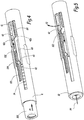
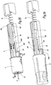
- an automatic injector or auto-injector 1 On the figure 1 is represented an automatic injector or auto-injector 1. At the figure 1 , all the components of the auto-injector 1 are not represented on the same line for the clarity of the drawing. However, all the components of the injector 1 are in practice aligned along the same longitudinal axis X1. Indeed, the auto-injector 1 has the appearance of a pen, that is to say it has a generally cylindrical shape centered on the axis X1.
- the injector 1 comprises an outer shell, or cover 2, which is generally of tubular geometry, centered on the longitudinal axis X1 in the mounted configuration of the injector 1.
- the injector 1 comprises a first longitudinal end 1a, which is designed to be turned towards the epidermis during injection and a second longitudinal end 1b, which is opposite the end 1a along the axis X1.
- the cover 2 is omitted for a better visualization of the internal components of the injector 1.
- a tubular casing 4 is arranged coaxially inside the cover 2 and is stationary relative thereto.
- the "forward” direction designates a direction going from the end 1b towards the end 1a and vice versa for the "rear” direction.
- a longitudinal direction designates a direction parallel to the longitudinal axis X1.
- a tip, or pusher, 10 of generally tubular geometry, is disposed coaxially inside the casing 4.
- the tip 10 comprises a front portion 100 which protrudes forward with respect to the casing 4 when the injector 1 is at rest.
- the end piece 10 is subjected to the elastic load action of a spiral spring 14, which is arranged inside the tubular casing 4, in contact with the end piece 10.
- the portion 100 has a front end 103 which is radially inwardly bent with respect to the axis X1.
- the end 103 forms an internal radial shoulder on which the spiral spring 14 is in abutment, exerting a force E14 elastic load directed forward.
- the tip 10 also includes a lug 101 which extends longitudinally from the portion 100 to the rear. This lug 101 carries a bolt 104 and a cam 102 which is disposed behind the bolt 104.
- the envelope 4 also contains a syringe 8 for administering or injecting a drug P.
- the drug, or active ingredient P may be a Atropine solution, which is an antidote to gas poisoning, or an adrenaline solution, used in case of cardiac malaise or severe allergic attack.
- the syringe 8 comprises a glass body 80, a hollow needle 84 and a piston 82 which is axially movable inside the body 80.
- the piston 82 is sometimes called a "piston seal" in the medical field since it is is an elastomer seal.
- the needle 84 is glued to the body 80 and is protected by a cover, or needle guard 86. Furthermore, the portion 100 of the tip 10 is provided to protect the needle 84 when the cover 86 is removed, so that to avoid an accidental sting.
- a push rod 6 of the piston 82 inside the syringe body 80 is also disposed inside the tubular casing 4.
- This rod 6 is made of plastic and is arranged axially with the syringe 8. It is more subject to the action of elastic loading of a spiral spring 16.
- a cap 12 closes the automatic injector 1 when it is not used.
- the cap 12 is secured axially, or in translation, with the needle guard 86.
- the cap 12 comprises tabs which surround the needle guard 86 and which are attached or “clipped” in the needle guard 86.
- the removal of the cap 12 integrally causes the withdrawal of the needle guard 86 of the syringe 8.
- the tubular envelope 4 delimits a cutout 40, whose contour is generally rectangular.
- An injection lever 41 extends from a rear lateral edge of the cutout 40 forwards.
- X41 denotes a longitudinal axis of the lever 41.
- the lever 41 has a front end 42 formed of two branches 42a and 42b which extend transversely to the longitudinal axis X41 of the lever 41.
- a guard lever 43 extends rearwardly from a front edge of the cutout 40, that is to say from an edge opposite to the attachment edge of the lever 41.
- X43 denotes a longitudinal axis of the lever 43.
- This guard lever 43 has a rear end 44, having a surface S44 of contact with the bolt 104 and a shoulder 440 for locking the bolt 104.
- the surface S44 is an inclined surface, which converges rearward towards the X43 axis.
- the casing 4 is made of plastic and the levers 41 and 43 are elastically deformable.
- the push rod 6 of the piston 82 comprises, at the rear, a tubular body 60 having an opening O6 for the passage of the spring 16 and a hollow shank 62 which extends from the body 60 towards the front and which is provided to push the piston 82 during the injection.
- the shank 62 is partially inserted into the syringe body 80, in contact with the piston 82.
- the shank 6 comprises an internal radial shoulder 61, which is disposed at the junction between the body 60 and the shank 62 and which forms a bearing surface for the spiral spring 16.
- the spiral spring 16 exerts a load E16 elastic load directed forward on the shoulder 61.
- the rod 6 carries a longitudinal rack 64 provided with several notches 640.
- This rack 64 is disposed at the rear of the shank 62, in particular at the same axial level as the body 60.
- the shank 6 also carries an anvil 66, which is arranged at the front with respect to the rack 64.
- the anvil 66 and the rack 64 define between them a hollow space, or housing 68.
- the tip 10 is axially movable, around the needle 84 and coaxially inside the casing 4, between an advanced position, where it protects, or surrounds, the needle 84 and a retracted position, where the needle 84 is discovered.
- the retracted position is, for example, represented in figure 5 .
- the advanced position is a position armed with the auto-injector 1, which is represented at the figure 4 . In this position, the auto-injector 1 is ready for use, that is to say that the cache 86 is removed.
- the injection lever 41 blocks the advance of the rod 6.
- the branch 42b of the end 42 belonging to the lever 41 blocks the advance of the rack 64 equipping the rod 6.
- the branch 42b of the end 42 is disposed on the advanced path of the rack 64. In other words, the branch 42b forms an obstacle to the passage of the rack 64.
- the lever 41 and the rack 64 thus together form means for blocking the advance of the rod 6. These means for blocking the advance of the rod 6 are initially activated when the nozzle 10 is in the advanced position.
- the bolt 104 of the tab 101 abuts against the surface S44 of the end 44 of the lever 43. More specifically, the bolt 104 bears against the surface S44 towards the front. The end 44 of the lever 43 thus blocks the advance of the bolt 104 and the surface S44 is a locking surface of the advance of the tip 10.
- the end 44 of the lever 43 is interposed, in a direction orthoradial to the axis X1, between the bolt 104 and the anvil 66 of the rod 6.
- the end 44, the bolt 104 and the anvil 106 are arranged at the same axial level and the end 44 is wedged, considering a direction orthoradial to the axis X1, between the bolt 104 and the anvil 66.
- the anvil 66 thus prevents the lever 43 from deforming elastically under the bearing action of the bolt 104, this action being directed forward.
- the lever 43 retains therefore its initial shape and prevents the bolt 104 to move forward, under the action of the spring 14.
- the user removes the cap 12 of the injector 1 and takes with the cap 12 the needle guard 86 since they are axially secured.
- the injector is then ready for use and the tip 10 is in its advanced position, as shown in FIG. figure 4 .
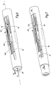
- the tip 10 thus uncovers the needle 84 in its movement and the needle 84 enters the epidermis in parallel with the recoil F1 of the tip 10.
- the cam 102 of the tab 101 moves back with the rest of the tip 10 and then comes into contact with the end 42 of the injection lever 41, that is to say that the tip 10 reaches the retracted position.
- the lever 41 deforms elastically under the pushing action of the cam 102 to the rear.
- This deformation of the lever 41 is a flexion F2 which is directed opposite to the rack 64, in a direction generally orthoradial to the axis X1.
- the flexion F2 causes the limb 42b of the end 42 to disengage from the forward trajectory of the rack 64, that is to say that the lever 41 switches to an unobstructed configuration of the rack 64, which releases the advanced movement of the rod 6 under the spring load E16 of the spring 16.
- the rod can then move forward, as represented by the arrow F3 at the figure 5 .
- the displacement of the tip 10 in its retracted position causes the deactivation of the locking means of the advance of the rod 6.
- the forward movement F3 of the rod 6 causes the start of the injection, that is to say that the piston 82 is pushed inside the syringe body 80 by the tail 62 and forces the active ingredient P contained in the body 80 to exit by the hollow needle 84.
- the injection of the active ingredient P of the syringe 8 is shown in FIG. figure 6 by the appearance of a drop G at the end of the needle 84.
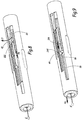
- the tip 10 leaves its retracted position, that is to say it returns to its advanced position through the E14 force, by expansion, or elastic return of the spring 14.
- the cam 102 stops acting on the injection lever 41 and the branch 42b resiliently returns to engagement with the rack 64.
- the displacement, in the course of injection, the tip 10 to its advanced position therefore causes the reactivation of the locking means of the advance of the rod 6.
- the tip 10 reaches its retracted position and is blocked in its forward movement. Indeed, as explained above, the movement of the bolt 104 forward is blocked by the end 44 of the lever 43, in cooperation with the anvil 66.
- the partial or total release of the pressure of the auto-injector 1 on the body of the user causes a return of the tip 10 to its advanced position, as represented by arrows F4 at the figure 6 .
- the lever 41 resumes its initial shape by elastic return towards the rack 64.
- the elastic return movement of the lever 41 is shown in FIG. figure 6 by an arrow F5 and implies that the branch 42b of the end 42 is housed in a notch 640 of the rack 64.
- the rack 64 is then locked in its movement by the lever 41.
- the rod 6 is then immobilized and the injection of the drug is temporarily stopped.
- the user can subsequently resume the injection by pressing his thigh again to push back the tip 10.
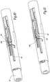
- a further retreat of the tip 10, represented by the arrow F6 to the figure 7 causes a recoil on the same stroke of the cam 102 which returns to contact with the end 42 of the injection lever 41.
- the contact action of the cam 102 in contact with the end 42 causes a new tilting F7 of the lever 41, out of the notches 640 of the rack 64.
- the rack 64 is then released from the retaining action of the lever 41 and the forward movement of the rod 6 continues, as represented by the arrow F8 at the figure 8 .
- the user withdraws the auto-injector 1 from his thigh and the tip 10 advances under the effect of the effort E14, as represented by the arrows F9 at the figure 9 .
- the end of the injection phase is represented by a drop G 'whose outline is schematically drawn in broken lines.
- the end 44 of the lever 43 is no longer disposed at the same axial level as the anvil 66 since the anvil 66 has moved forward following the advance of the rod 6 and has passed the end 44.
- the anvil 66 is then in front of the end 44 of the lever 43. More specifically, the end 44 is at the same axial level as the housing 68 interposed between the anvil 66 and the rack 64 .
- the bolt 104 comes into contact with the surface S44 of the end 44 and the thrust force of the bolt 102 towards the front, on the surface S44, causes a tilting F10 of the lever 43 so that the end 44 is housed temporarily in the housing 68 of the rod 6. In fact, the anvil 66 no longer prevents the elastic deformation of the guard lever 43. The bolt 104 of the nozzle 10 therefore passes in front of the end 44 of the lever 43. The tip 10 is then in an advanced position of end of injection shown in the figure 11 , which is an even more forward position with respect to the advanced position.
- the lever 43 resumes its initial shape by spring return F11. Therefore, the shoulder 440 of the end 44 opposes the recoil of the tip 10. In other words, the shoulder 440 forms a stop blocking the recoil movement of the bolt 104.
- the lever 43 and the bolt 104 thus together form locking means of the tip 10 in the advanced end of injection, which oppose the recoil of the tip after injection. This is a safety for the user since the needle 84 can not be discovered after the injector has been used. There is therefore no risk of accidental puncture by the needle 84 and the tip 10 is maintained in the end of injection position.
- FIG. 12 to 16 there is shown a second embodiment of the automatic injector 1.
- the elements of the injector 1 which are identical or which operate in a manner similar to those of the injector of the first embodiment retain their numerical reference, whereas the additional elements or which function differently carry other numerical references. .
- the tip 10 also has a front portion 100 which protrudes from the tubular casing 4 towards the front.
- Two wings 106 extend from the body 100 backwards. These fins 106 are elastically deformable and each have a rear end 108.
- the auto-injector 1 is symmetrical with respect to a median plane containing the longitudinal axis X1. Thus, two other fins are arranged on the opposite side to the angle of view of Figures 12 to 16 . In the remainder of the description, only the elements arranged on the visible side are described because the corresponding symmetrical elements are identical.
- a shank 62 belonging to a push rod 6 of the piston inside the syringe body is clamped between the two ends 108 of the fins 106. More specifically, the shank 62 has a width, measured in a direction orthoradial to the X1 axis, which is greater than or equal to the spacing between the fins 106, measured in the same direction.
- the ends 108 of the fins 106 each comprise a bearing surface S108A against the shank 62 of the shank 6 and an inclined surface S108B, which is opposite to the bearing surface S108A on the shank 62. More specifically, the surfaces S108B diverge. , with respect to a longitudinal axis X62 of the tail 62, towards the rear. Surfaces S108A and S108B are marked at the figure 14 where only the outer radial trace of the surfaces S108A is visible since they bear against the shank 62. These S108A surfaces are parallel to each other and to the axis X1.
- the surfaces S108B are complementary to two surfaces S46 belonging to two seats 46. Otherwise formulated, the surfaces S46 diverge rearwardly with respect to the longitudinal axis X62 of the shank 62, with the same inclination as that of the surfaces S108B.
- the seats 46 belong to the casing 4 and are arranged at the same axial level.
- the fins 106 are disposed between these two seats 46 and on either side of the shank 62, with respect to a direction orthoradial to the axis X1.
- the rod 6 is permanently subjected to an elastic load force of a spring 16, which tends to push the rod 6 forward.
- This pushing force of the rod 6, which is similar to the force E16 of the first embodiment, tends to move the fins 106 away from each other by elastic deformation, to let the tail 62 pass.
- the tip 10 is axially movable against the elastic load action of a spring not shown and comparable to the spring 14, between an advanced position, shown in FIG. figure 13 and a retracted position, represented in figure 15 .
- a finger 69 carried by the push rod 6 is in contact with a surface S460 of a seat 46, on the opposite side to the fins 106.
- This finger 69 is an elastic finger, or elastically deformable. At rest and more generally until the injection is completed, the finger 69 is crushed or pressed against the surface S460 of the abutments 46. Furthermore, the surface S460 is opposite the surface S46 of the abutments 46.
- the fins 106 further comprise, at the front relative to the ends 108, each a shoulder 109 which widens the fins 106 and which is turned towards the rear.
- S109 designates a lateral surface of the fins 106, this surface being disposed in the extension of the surface S108 forward, after passing the shoulder 109.
- the user removes the cap 12 as represented by the arrow F12 at the figure 13 and takes, as in the first embodiment, the needle guard 86 with the cap 12 since they are secured axially .. Then, the user applies the injector 1 on a part of his body, such as his thigh. The action of contact of the injector 1 on the thigh of the user tends to push back the tip 10, as represented by the arrow F13 at the figure 13 . The ends 108 of the fins 106 then take off seats 46, as shown in FIG. figure 14 .
- the ends 108 of the fins 106 are no longer held by the seats 46 in firm support against the tail 62, so that the fins 106 can deform elastically.
- the elastic load action of the spring 16 then causes the elastic deformation of the fins 106 to let the tail 62 of the rod 6. More specifically, the fins 106 move away from each other, or flex, to let pass the tail 62, as represented by the arrows F14 at the figure 14 .
- the deflection F14 of the fins 106 is carried out in practice transversely to the axis X62.
- the rod 6 slides axially forward and the piston is moved inside the syringe body.
- the locking means of the advance of the rod 6 are deactivated and the injection begins, as symbolized by a drop G at the figure 14 .
- the advance of the rod 6 is represented at figure 14 by an arrow F15.
- the tip 10 reaches the retracted position to disable the blocking means of the advance of the rod 6. Indeed, these means are deactivated as soon as possible.
- the elastic finger 69 rubs against the surface S460 of the abutment 46 during the displacement of the rod 6.
- the tip 10 If the user accidentally removes the injector 1 from his thigh during the injection, the tip 10 returns to its advanced position under the elastic load action of the compressed spring during the retraction of the tip 10.
- the surfaces S108B of the ends 108 of the fins 106 abut against the surfaces S46 of the seats 46.
- the fins 106 return to their initial position in contact with the seats 46 and the seats 46 then prevent again the elastic deformation of the fins 106.
- the tail 62 of the rod 6 is again held in a vice between the two fins 106, which prevents the advance of the rod 6.
- the return of the tip 10 in its advanced position causes the reactivation of the locking means of the advance of the rod 6 and the injection is then temporarily stopped.
- the user again applies the injector 1 on his thigh and presses to push back the tip 10.
- the recoil of the tip 10 implies the resumption of the movement of the advance of the rod 6 and the continuation of the injection.
- the finger 69 of the rod 6 is no longer blocked by the seat 46 and resumes its initial shape by elastic return, as represented by the arrow F16 at the figure 15 .
- the elastic return of the finger 69 to be interpreted as a pivoting movement and the finger 69 is housed in a space E1 disposed between a front end 462 of the seat 46 and the shoulder 109 of a fin 106.
- figure 15 the end of the injection phase is symbolized by a drop G 'whose contour is made in broken lines.
- the tip 10 advances under the elastic load action of the spring and returns to the advanced position.
- the finger 69 of the rod 6 is again slightly compressed in contact with the surface S109 of the fin 106, to let the fins 106 pass.
- the fins 106 force the passage to the advanced position by compressing the finger 69.
- the finger 69 returns to its original shape by springback and is lodged against the shoulder 109 of the fin 106.
- the finger 69 forms an obstacle to the retraction of the fins 106 of the tip 10.
- the finger 69 can therefore be interpreted as a locking means of the tip 10 in an advanced end of injection. This means opposes the recoil of the tip 10 after the injection. Thus, the user is not likely to injure himself with the needle 84 by accidentally pressing the tip 10 since the tip 10 is locked in the advanced position.
- the automatic injector 1 can be used to perform a bite on any other part of the body that the thigh.
- the active ingredient P used may be a drug other than a solution of adrenaline or atropine.
- the automatic injector 1 can be rechargeable.
Landscapes
- Health & Medical Sciences (AREA)
- Engineering & Computer Science (AREA)
- Heart & Thoracic Surgery (AREA)
- Vascular Medicine (AREA)
- Anesthesiology (AREA)
- Biomedical Technology (AREA)
- Hematology (AREA)
- Life Sciences & Earth Sciences (AREA)
- Animal Behavior & Ethology (AREA)
- General Health & Medical Sciences (AREA)
- Public Health (AREA)
- Veterinary Medicine (AREA)
- Environmental & Geological Engineering (AREA)
- Infusion, Injection, And Reservoir Apparatuses (AREA)
Claims (9)
- Automatischer Injektor (1), Folgendes aufweisend:- eine Kappe (2), die sich entlang einer Längsachse (X1) erstreckt,- eine Spritze (8) zum Injizieren eines Medikaments (P), die im Inneren der Kappe angeordnet ist und eine Nadel (84), einen Nadelschutz (86), einen Körper (80) und einen Kolben (82) hat,- einen Schaft (6) zum Schieben des Kolbens im Inneren des Spritzenkörpers, der bei einer Injektion durch eine von einer ersten Feder (16) ausgeübte elastische Belastungskraft (E16) axial nach vorne verschoben wird,- einen Stutzen (10) zum Schutz der Nadel, der axial um die Nadel herum und entgegen einer von einer zweiten Feder (14) ausgeübten elastischen Belastungskraft (E14) zwischen einer ausgefahrenen Position (Figur 2; Figur 13), in der er die Nadel umgibt, und einer eingefahrenen Position (Figur 8; Figur 14) verschiebbar ist, in der die Nadel offenliegt,- Einrichtungen (41, 64; 106, 46) zum Blockieren des Ausfahrens des Schafts,dadurch gekennzeichnet, dass:- die Blockierungseinrichtungen (41, 64; 106, 46) dazu ausgelegt sind, desaktiviert zu sein, wenn der Stutzen (10) zu seiner eingefahrenen Position (Figur 8; Figur 14) verschoben wird oder diese Position erreicht, und im Verlauf einer Injektion reaktiviert zu sein, wenn der Stutzen zu seiner ausgefahrenen Position (Figur 2; Figur 13) verschoben wird oder diese Position erreicht, und- die Einrichtungen (41, 64) zum Blockieren des Ausfahrens des Schafts (6) aufweisen:- einen ersten Hebel (41) zum Blockieren der Verschiebung des Schafts, der vorgesehen ist, um die Vorwärtsbewegung einer Zahnstange (64) zu blockieren, die am Schiebeschaft (6) ausgebildet ist, wobei der Stutzen (10) einen Nocken (102) zur Freisetzung der Blockierungswirkung des ersten Hebels (41) an der Zahnstange (64) aufweist, wobei dieser Nocken das Kippen (F2) des ersten Hebels in eine von der Zahnstange freigesetzte Auslegung bewirkt, wenn der Stutzen die eingefahrene Position erreicht, oder- zwei elastische Rippen (106), die zum Stutzen (10) gehören und beidseits des Schiebeschafts (6) angeordnet sind, und zwei Anschläge (46) zum Blockieren der elastischen Rippen in einer Position (Figur 13), in der die elastischen Rippen den Schaft zwischen sich eingespannt halten.
- Automatischer Injektor nach Anspruch 1, dadurch gekennzeichnet, dass der erste Hebel (41) elastisch verformbar ist und zu Injektionsbeginn bei Kontakt des Nockens (102) verformt wird, um aus der Durchtrittsbahn der Zahnstange (64) zu kippen.
- Automatischer Injektor nach Anspruch 2, dadurch gekennzeichnet, dass der erste Hebel (41) dazu ausgelegt ist, seine Ausgangsform durch elastische Rückstellung (F5) wieder anzunehmen, wenn der Stutzen im Verlauf einer Injektion in seine ausgefahrene Position zurückkehrt, und dass diese elastische Rückstellung (F5) einen Teil (42b) des Hebels dazu bringt, sich in eine Kerbe (640) der Zahnstange (64) einzupassen, wodurch das Ausfahren des Schiebeschafts (6) verhindert wird.
- Automatischer Injektor nach Anspruch 1, dadurch gekennzeichnet, dass die Rippen (106) jeweils eine Fläche (S108B) zur Anlage an einem Anschlag (46) aufweisen, die in Bezug auf eine Längsachse (X62) des Schafts (6) parallel zur Längsachse (X1) geneigt und komplementär zu einer Kontaktfläche (S46) des Anschlags ist.
- Automatischer Injektor nach einem der vorhergehenden Ansprüche, dadurch gekennzeichnet, dass er darüber hinaus Einrichtungen (43, 104; 69) zur Verriegelung des Stutzens (10) in einer ausgefahrenen Injektionsendposition (Figur 11; Figur 16) aufweist, die sich dem Rückzug des Stutzens nach der Injektion entgegensetzen.
- Automatischer Injektor nach Anspruch 5, dadurch gekennzeichnet, dass die Einrichtungen zur Verriegelung des Stutzens einen zum Schaft (6) gehörenden elastischen Finger (69) aufweisen, der sich am Ende einer Injektion durch elastische Rückstellung verschwenkt (F16), um den Rückzug der Rippen (106) des Stutzens (10) zu blockieren.
- Automatischer Injektor nach Anspruch 5, dadurch gekennzeichnet, dass die Verriegelungseinrichtungen einen zweiten Hebel (43) zum Blockieren der Verschiebung des Stutzens (10) aufweisen, der dazu vorgesehen ist, mit einem vom Stutzen getragenen Riegel (104) zusammenzuwirken, wobei sich dieser zweite Hebel dem Rückzug des Riegels des Stutzens entgegensetzt, wenn sich der Stutzen in der Injektionsendposition (Figur 11) befindet.
- Automatischer Injektor nach Anspruch 7, dadurch gekennzeichnet, dass der zweite Hebel (43) elastisch verformbar ist, und dass der Schaft (6) einen Amboss (66) zum Halten des zweiten Hebels (43) während der Injektion aufweist, der den zweiten Hebel daran hindert, sich bei Kontakt des Riegels zu verformen, solange die Injektion nicht abgeschlossen ist.
- Automatischer Injektor nach Anspruch 8, dadurch gekennzeichnet, dass der Amboss (66) am Schaft (6) eingerichtet ist, um mit dem Halten des zweiten Hebels (43) am Ende einer Injektion aufzuhören, wobei sich der zweite Hebel dann bei Kontakt des Riegels verformt, um die Verschiebung des Stutzens zu seiner Injektionsendposition freizugeben, und seine Ausgangsform durch elastische Rückstellung (F11) in eine Position (Figur 11) wieder annimmt, in der er sich dem Rückzug des Riegels des Stutzens entgegensetzt.
Priority Applications (1)
| Application Number | Priority Date | Filing Date | Title |
|---|---|---|---|
| PL15700691T PL3096819T3 (pl) | 2014-01-20 | 2015-01-19 | Iniektor automatyczny |
Applications Claiming Priority (2)
| Application Number | Priority Date | Filing Date | Title |
|---|---|---|---|
| FR1450417A FR3016523B1 (fr) | 2014-01-20 | 2014-01-20 | Injecteur automatique |
| PCT/EP2015/050848 WO2015107180A1 (fr) | 2014-01-20 | 2015-01-19 | Injecteur automatique |
Publications (2)
| Publication Number | Publication Date |
|---|---|
| EP3096819A1 EP3096819A1 (de) | 2016-11-30 |
| EP3096819B1 true EP3096819B1 (de) | 2018-06-06 |
Family
ID=50290155
Family Applications (1)
| Application Number | Title | Priority Date | Filing Date |
|---|---|---|---|
| EP15700691.7A Active EP3096819B1 (de) | 2014-01-20 | 2015-01-19 | Automatischer injektor |
Country Status (13)
| Country | Link |
|---|---|
| US (1) | US10105496B2 (de) |
| EP (1) | EP3096819B1 (de) |
| JP (1) | JP6599359B2 (de) |
| CN (1) | CN106413777B (de) |
| AU (1) | AU2015207514B2 (de) |
| BR (1) | BR112016015364B1 (de) |
| CA (1) | CA2935460C (de) |
| ES (1) | ES2685829T3 (de) |
| FR (1) | FR3016523B1 (de) |
| PL (1) | PL3096819T3 (de) |
| PT (1) | PT3096819T (de) |
| RU (1) | RU2670686C9 (de) |
| WO (1) | WO2015107180A1 (de) |
Cited By (1)
| Publication number | Priority date | Publication date | Assignee | Title |
|---|---|---|---|---|
| US12453819B2 (en) | 2018-07-24 | 2025-10-28 | Antares Pharma, Inc. | Injector |
Families Citing this family (17)
| Publication number | Priority date | Publication date | Assignee | Title |
|---|---|---|---|---|
| FR3016523B1 (fr) | 2014-01-20 | 2017-08-11 | Biocorp Rech Et Dev | Injecteur automatique |
| US11097067B2 (en) * | 2017-04-25 | 2021-08-24 | Cc Biotechnology Corporation | Injection pen |
| CA3099358A1 (en) | 2018-05-24 | 2019-11-28 | Novartis Ag | Automatic drug delivery device |
| EP3574947B1 (de) * | 2018-06-01 | 2023-08-30 | Tianjin Huahong Technology Co., Ltd. | Wegwerfbare injektionsnadel |
| EP4603124A3 (de) | 2018-06-08 | 2025-11-12 | Antares Pharma, Inc. | Injektor mit automatischer insertion |
| GB2577537A (en) * | 2018-09-28 | 2020-04-01 | Owen Mumford Ltd | Injection device fill volume management |
| CN209967279U (zh) | 2018-12-27 | 2020-01-21 | 宁波美生医疗器材有限公司 | 一种安全型注射装置和注射器 |
| CN113490521B (zh) | 2019-02-26 | 2023-05-02 | 贝克顿迪金森法国公司 | 带有帽的自动注射器 |
| CN113474025B (zh) | 2019-02-26 | 2023-12-01 | 贝克顿迪金森法国公司 | 具有声频指示器的自动注射器 |
| KR102615193B1 (ko) | 2019-02-26 | 2023-12-19 | 벡톤 디킨슨 프랑스 | 자동 주사 장치를 위한 낙하 테스트 특징부를 구비한 강성 바늘 쉴드 분리기 |
| CN111407977B (zh) * | 2020-04-08 | 2022-10-21 | 北京航宇阳光机电技术研究所 | 一种自动注射装置 |
| CH717905A2 (de) | 2020-09-30 | 2022-03-31 | Ypsomed Ag | Autoinjektor mit Ausschüttstopp. |
| CN112076364B (zh) * | 2020-10-16 | 2024-05-17 | 山东威高普瑞医药包装有限公司 | 一种自动注射器 |
| CN113144345A (zh) * | 2021-05-12 | 2021-07-23 | 苏州嘉树医疗科技有限公司 | 一种自动注射器用触发装置 |
| CN115025334B (zh) * | 2022-06-09 | 2025-10-10 | 南京鈊帝医疗科技有限公司 | 自动注射器 |
| EP4374896A1 (de) * | 2022-11-25 | 2024-05-29 | Inductio AG | Antriebseinheit für eine medizinische spritze, spritze mit einer derartigen antriebs-einheit und autoinjektor |
| CN117379641A (zh) * | 2023-10-15 | 2024-01-12 | 中山汇丰医用包装科技有限公司 | 一种一次性自动笔式注射器 |
Family Cites Families (17)
| Publication number | Priority date | Publication date | Assignee | Title |
|---|---|---|---|---|
| GB8926825D0 (en) | 1989-11-28 | 1990-01-17 | Glaxo Group Ltd | Device |
| DE69319753T2 (de) * | 1992-11-19 | 1999-04-15 | Tebro S.A., Luxembourg | Automatische injektionsvorrichtung für vorgefüllte spritzen |
| US5478316A (en) * | 1994-02-02 | 1995-12-26 | Becton, Dickinson And Company | Automatic self-injection device |
| FR2733155B1 (fr) | 1995-04-18 | 1997-09-19 | Tebro | Auto-injecteur rechargeable |
| RU2101522C1 (ru) * | 1995-11-24 | 1998-01-10 | Владислав Иванович Третьяков | Поршень для автоматического изменения степени сжатия двигателя |
| US20050222539A1 (en) * | 2004-03-30 | 2005-10-06 | Pediamed Pharmaceuticals, Inc. | Automatic injection device |
| FR2905273B1 (fr) * | 2006-09-06 | 2009-04-03 | Becton Dickinson France Soc Pa | Dispositif d'injection automatique avec moyen de temporisation. |
| CN101854967B (zh) * | 2007-09-25 | 2013-06-05 | 贝克顿迪金森法国公司 | 具有能由安全护套移动的解除作用装置的自动注射器 |
| WO2009040602A1 (en) * | 2007-09-25 | 2009-04-02 | Becton Dickinson France | Autoinject0r with deactivating means moveable by a safety shield |
| JP5563579B2 (ja) * | 2008-09-29 | 2014-07-30 | ベクトン ディキンソン フランス | 自動注射装置 |
| EP2438947A1 (de) * | 2010-10-08 | 2012-04-11 | Sanofi-Aventis Deutschland GmbH | Automatischer Injektor |
| EP2468329A1 (de) * | 2010-12-21 | 2012-06-27 | Sanofi-Aventis Deutschland GmbH | Automatischer Injektor mit Torsionsfeder |
| EP2489381A1 (de) * | 2011-02-18 | 2012-08-22 | Sanofi-Aventis Deutschland GmbH | Automatischer Injektor |
| EP2489380A1 (de) * | 2011-02-18 | 2012-08-22 | Sanofi-Aventis Deutschland GmbH | Injektionsvorrichtung |
| EP2489384A1 (de) * | 2011-02-18 | 2012-08-22 | Sanofi-Aventis Deutschland GmbH | Automatischer Injektor |
| EP2596826A1 (de) * | 2011-11-24 | 2013-05-29 | Sanofi-Aventis Deutschland GmbH | Sicherheitsspritze |
| FR3016523B1 (fr) | 2014-01-20 | 2017-08-11 | Biocorp Rech Et Dev | Injecteur automatique |
-
2014
- 2014-01-20 FR FR1450417A patent/FR3016523B1/fr not_active Expired - Fee Related
-
2015
- 2015-01-19 BR BR112016015364-2A patent/BR112016015364B1/pt active IP Right Grant
- 2015-01-19 US US15/110,933 patent/US10105496B2/en active Active
- 2015-01-19 PL PL15700691T patent/PL3096819T3/pl unknown
- 2015-01-19 EP EP15700691.7A patent/EP3096819B1/de active Active
- 2015-01-19 CN CN201580004943.4A patent/CN106413777B/zh active Active
- 2015-01-19 AU AU2015207514A patent/AU2015207514B2/en active Active
- 2015-01-19 JP JP2016564406A patent/JP6599359B2/ja active Active
- 2015-01-19 PT PT15700691T patent/PT3096819T/pt unknown
- 2015-01-19 RU RU2016129583A patent/RU2670686C9/ru active
- 2015-01-19 CA CA2935460A patent/CA2935460C/fr active Active
- 2015-01-19 WO PCT/EP2015/050848 patent/WO2015107180A1/fr not_active Ceased
- 2015-01-19 ES ES15700691.7T patent/ES2685829T3/es active Active
Non-Patent Citations (1)
| Title |
|---|
| None * |
Cited By (1)
| Publication number | Priority date | Publication date | Assignee | Title |
|---|---|---|---|---|
| US12453819B2 (en) | 2018-07-24 | 2025-10-28 | Antares Pharma, Inc. | Injector |
Also Published As
| Publication number | Publication date |
|---|---|
| CN106413777A (zh) | 2017-02-15 |
| AU2015207514B2 (en) | 2019-02-21 |
| WO2015107180A1 (fr) | 2015-07-23 |
| AU2015207514A1 (en) | 2016-08-11 |
| JP2017502815A (ja) | 2017-01-26 |
| RU2670686C1 (ru) | 2018-10-24 |
| PT3096819T (pt) | 2018-10-15 |
| FR3016523B1 (fr) | 2017-08-11 |
| EP3096819A1 (de) | 2016-11-30 |
| RU2670686C9 (ru) | 2018-12-13 |
| CN106413777B (zh) | 2019-11-26 |
| PL3096819T3 (pl) | 2018-11-30 |
| CA2935460C (fr) | 2021-09-28 |
| RU2016129583A (ru) | 2018-01-24 |
| BR112016015364A2 (pt) | 2017-08-08 |
| BR112016015364B1 (pt) | 2021-11-30 |
| US20160331905A1 (en) | 2016-11-17 |
| ES2685829T3 (es) | 2018-10-11 |
| JP6599359B2 (ja) | 2019-10-30 |
| CA2935460A1 (fr) | 2015-07-23 |
| FR3016523A1 (fr) | 2015-07-24 |
| US10105496B2 (en) | 2018-10-23 |
Similar Documents
| Publication | Publication Date | Title |
|---|---|---|
| EP3096819B1 (de) | Automatischer injektor | |
| EP1185323B1 (de) | Einweginjektionsvorrichtung | |
| EP1605997B1 (de) | Nadelschutzvorrichtung für eine spritze, und injektionsvorrichtung mit einer spritze und dieser nadelschutzvorrichtung | |
| EP1436026B1 (de) | Sicherheitsvorrichtung für eine spritze | |
| EP1053037B1 (de) | Vorrichtung zur automatischen injektion einer dosis eines medikamentenprodukts | |
| EP1148904B1 (de) | Sicherheitsanordnung für spritze vorgefüllt mit flüssigem arzneimittel | |
| EP1781359A1 (de) | Schutzvorrichtung für spritzennadel und injektionsvorrichtung damit | |
| EP3313477B1 (de) | Spritze mit einer gebundenen nadel | |
| EP1485153A2 (de) | Nadelschutzvorrichtung für eine spritze sowie injektionsvorrichtung bestehend aus einer spritze und dieser schutzvorrichtung | |
| EP3352819B1 (de) | Automatischer injektor | |
| FR2862542A1 (fr) | Dispositif de protection d'aiguille destine a une carpule, et dispositif d'injection comprenant une carpule et ce dispositif de protection | |
| FR2930162A1 (fr) | Ensemble de protection d'aiguille comportant un element de verrouillage. | |
| FR2884721A1 (fr) | Ensemble d'injection et dispositif d'assistance a l'injection | |
| FR2930161A1 (fr) | Ensemble de protection d'aiguille comportant un element de verrouillage mobile radialement. | |
| FR3013601A1 (fr) | Autoinjecteur. | |
| EP1356839B1 (de) | Anordnung einer Flüssigkeitsinjektionsspritze und Hülse für diese Anordnung |
Legal Events
| Date | Code | Title | Description |
|---|---|---|---|
| PUAI | Public reference made under article 153(3) epc to a published international application that has entered the european phase |
Free format text: ORIGINAL CODE: 0009012 |
|
| 17P | Request for examination filed |
Effective date: 20160707 |
|
| AK | Designated contracting states |
Kind code of ref document: A1 Designated state(s): AL AT BE BG CH CY CZ DE DK EE ES FI FR GB GR HR HU IE IS IT LI LT LU LV MC MK MT NL NO PL PT RO RS SE SI SK SM TR |
|
| AX | Request for extension of the european patent |
Extension state: BA ME |
|
| DAX | Request for extension of the european patent (deleted) | ||
| REG | Reference to a national code |
Ref country code: DE Ref legal event code: R079 Ref document number: 602015011789 Country of ref document: DE Free format text: PREVIOUS MAIN CLASS: A61M0005200000 Ipc: A61M0005315000 |
|
| GRAP | Despatch of communication of intention to grant a patent |
Free format text: ORIGINAL CODE: EPIDOSNIGR1 |
|
| STAA | Information on the status of an ep patent application or granted ep patent |
Free format text: STATUS: GRANT OF PATENT IS INTENDED |
|
| RIC1 | Information provided on ipc code assigned before grant |
Ipc: A61M 5/32 20060101ALI20171127BHEP Ipc: A61M 5/20 20060101ALI20171127BHEP Ipc: A61M 5/315 20060101AFI20171127BHEP |
|
| INTG | Intention to grant announced |
Effective date: 20171219 |
|
| RIN1 | Information on inventor provided before grant (corrected) |
Inventor name: ANEAS, ANTOINE |
|
| GRAS | Grant fee paid |
Free format text: ORIGINAL CODE: EPIDOSNIGR3 |
|
| GRAA | (expected) grant |
Free format text: ORIGINAL CODE: 0009210 |
|
| STAA | Information on the status of an ep patent application or granted ep patent |
Free format text: STATUS: THE PATENT HAS BEEN GRANTED |
|
| AK | Designated contracting states |
Kind code of ref document: B1 Designated state(s): AL AT BE BG CH CY CZ DE DK EE ES FI FR GB GR HR HU IE IS IT LI LT LU LV MC MK MT NL NO PL PT RO RS SE SI SK SM TR |
|
| REG | Reference to a national code |
Ref country code: GB Ref legal event code: FG4D Free format text: NOT ENGLISH |
|
| REG | Reference to a national code |
Ref country code: CH Ref legal event code: EP Ref country code: AT Ref legal event code: REF Ref document number: 1005350 Country of ref document: AT Kind code of ref document: T Effective date: 20180615 |
|
| REG | Reference to a national code |
Ref country code: IE Ref legal event code: FG4D Free format text: LANGUAGE OF EP DOCUMENT: FRENCH |
|
| REG | Reference to a national code |
Ref country code: DE Ref legal event code: R096 Ref document number: 602015011789 Country of ref document: DE |
|
| REG | Reference to a national code |
Ref country code: NL Ref legal event code: FP |
|
| REG | Reference to a national code |
Ref country code: SE Ref legal event code: TRGR |
|
| REG | Reference to a national code |
Ref country code: CH Ref legal event code: NV Representative=s name: MICHELI AND CIE SA, CH |
|
| REG | Reference to a national code |
Ref country code: ES Ref legal event code: FG2A Ref document number: 2685829 Country of ref document: ES Kind code of ref document: T3 Effective date: 20181011 |
|
| REG | Reference to a national code |
Ref country code: PT Ref legal event code: SC4A Ref document number: 3096819 Country of ref document: PT Date of ref document: 20181015 Kind code of ref document: T Free format text: AVAILABILITY OF NATIONAL TRANSLATION Effective date: 20180831 |
|
| REG | Reference to a national code |
Ref country code: LT Ref legal event code: MG4D |
|
| PG25 | Lapsed in a contracting state [announced via postgrant information from national office to epo] |
Ref country code: BG Free format text: LAPSE BECAUSE OF FAILURE TO SUBMIT A TRANSLATION OF THE DESCRIPTION OR TO PAY THE FEE WITHIN THE PRESCRIBED TIME-LIMIT Effective date: 20180906 Ref country code: CY Free format text: LAPSE BECAUSE OF FAILURE TO SUBMIT A TRANSLATION OF THE DESCRIPTION OR TO PAY THE FEE WITHIN THE PRESCRIBED TIME-LIMIT Effective date: 20180606 Ref country code: LT Free format text: LAPSE BECAUSE OF FAILURE TO SUBMIT A TRANSLATION OF THE DESCRIPTION OR TO PAY THE FEE WITHIN THE PRESCRIBED TIME-LIMIT Effective date: 20180606 Ref country code: FI Free format text: LAPSE BECAUSE OF FAILURE TO SUBMIT A TRANSLATION OF THE DESCRIPTION OR TO PAY THE FEE WITHIN THE PRESCRIBED TIME-LIMIT Effective date: 20180606 Ref country code: NO Free format text: LAPSE BECAUSE OF FAILURE TO SUBMIT A TRANSLATION OF THE DESCRIPTION OR TO PAY THE FEE WITHIN THE PRESCRIBED TIME-LIMIT Effective date: 20180906 |
|
| PG25 | Lapsed in a contracting state [announced via postgrant information from national office to epo] |
Ref country code: HR Free format text: LAPSE BECAUSE OF FAILURE TO SUBMIT A TRANSLATION OF THE DESCRIPTION OR TO PAY THE FEE WITHIN THE PRESCRIBED TIME-LIMIT Effective date: 20180606 Ref country code: RS Free format text: LAPSE BECAUSE OF FAILURE TO SUBMIT A TRANSLATION OF THE DESCRIPTION OR TO PAY THE FEE WITHIN THE PRESCRIBED TIME-LIMIT Effective date: 20180606 Ref country code: GR Free format text: LAPSE BECAUSE OF FAILURE TO SUBMIT A TRANSLATION OF THE DESCRIPTION OR TO PAY THE FEE WITHIN THE PRESCRIBED TIME-LIMIT Effective date: 20180907 Ref country code: LV Free format text: LAPSE BECAUSE OF FAILURE TO SUBMIT A TRANSLATION OF THE DESCRIPTION OR TO PAY THE FEE WITHIN THE PRESCRIBED TIME-LIMIT Effective date: 20180606 |
|
| REG | Reference to a national code |
Ref country code: AT Ref legal event code: MK05 Ref document number: 1005350 Country of ref document: AT Kind code of ref document: T Effective date: 20180606 |
|
| PG25 | Lapsed in a contracting state [announced via postgrant information from national office to epo] |
Ref country code: RO Free format text: LAPSE BECAUSE OF FAILURE TO SUBMIT A TRANSLATION OF THE DESCRIPTION OR TO PAY THE FEE WITHIN THE PRESCRIBED TIME-LIMIT Effective date: 20180606 Ref country code: SK Free format text: LAPSE BECAUSE OF FAILURE TO SUBMIT A TRANSLATION OF THE DESCRIPTION OR TO PAY THE FEE WITHIN THE PRESCRIBED TIME-LIMIT Effective date: 20180606 Ref country code: CZ Free format text: LAPSE BECAUSE OF FAILURE TO SUBMIT A TRANSLATION OF THE DESCRIPTION OR TO PAY THE FEE WITHIN THE PRESCRIBED TIME-LIMIT Effective date: 20180606 Ref country code: IS Free format text: LAPSE BECAUSE OF FAILURE TO SUBMIT A TRANSLATION OF THE DESCRIPTION OR TO PAY THE FEE WITHIN THE PRESCRIBED TIME-LIMIT Effective date: 20181006 Ref country code: AT Free format text: LAPSE BECAUSE OF FAILURE TO SUBMIT A TRANSLATION OF THE DESCRIPTION OR TO PAY THE FEE WITHIN THE PRESCRIBED TIME-LIMIT Effective date: 20180606 Ref country code: EE Free format text: LAPSE BECAUSE OF FAILURE TO SUBMIT A TRANSLATION OF THE DESCRIPTION OR TO PAY THE FEE WITHIN THE PRESCRIBED TIME-LIMIT Effective date: 20180606 |
|
| PG25 | Lapsed in a contracting state [announced via postgrant information from national office to epo] |
Ref country code: SM Free format text: LAPSE BECAUSE OF FAILURE TO SUBMIT A TRANSLATION OF THE DESCRIPTION OR TO PAY THE FEE WITHIN THE PRESCRIBED TIME-LIMIT Effective date: 20180606 |
|
| REG | Reference to a national code |
Ref country code: DE Ref legal event code: R097 Ref document number: 602015011789 Country of ref document: DE |
|
| PLBE | No opposition filed within time limit |
Free format text: ORIGINAL CODE: 0009261 |
|
| STAA | Information on the status of an ep patent application or granted ep patent |
Free format text: STATUS: NO OPPOSITION FILED WITHIN TIME LIMIT |
|
| 26N | No opposition filed |
Effective date: 20190307 |
|
| PG25 | Lapsed in a contracting state [announced via postgrant information from national office to epo] |
Ref country code: SI Free format text: LAPSE BECAUSE OF FAILURE TO SUBMIT A TRANSLATION OF THE DESCRIPTION OR TO PAY THE FEE WITHIN THE PRESCRIBED TIME-LIMIT Effective date: 20180606 Ref country code: DK Free format text: LAPSE BECAUSE OF FAILURE TO SUBMIT A TRANSLATION OF THE DESCRIPTION OR TO PAY THE FEE WITHIN THE PRESCRIBED TIME-LIMIT Effective date: 20180606 |
|
| PG25 | Lapsed in a contracting state [announced via postgrant information from national office to epo] |
Ref country code: AL Free format text: LAPSE BECAUSE OF FAILURE TO SUBMIT A TRANSLATION OF THE DESCRIPTION OR TO PAY THE FEE WITHIN THE PRESCRIBED TIME-LIMIT Effective date: 20180606 |
|
| PG25 | Lapsed in a contracting state [announced via postgrant information from national office to epo] |
Ref country code: TR Free format text: LAPSE BECAUSE OF FAILURE TO SUBMIT A TRANSLATION OF THE DESCRIPTION OR TO PAY THE FEE WITHIN THE PRESCRIBED TIME-LIMIT Effective date: 20180606 |
|
| PG25 | Lapsed in a contracting state [announced via postgrant information from national office to epo] |
Ref country code: MT Free format text: LAPSE BECAUSE OF FAILURE TO SUBMIT A TRANSLATION OF THE DESCRIPTION OR TO PAY THE FEE WITHIN THE PRESCRIBED TIME-LIMIT Effective date: 20180606 |
|
| PG25 | Lapsed in a contracting state [announced via postgrant information from national office to epo] |
Ref country code: HU Free format text: LAPSE BECAUSE OF FAILURE TO SUBMIT A TRANSLATION OF THE DESCRIPTION OR TO PAY THE FEE WITHIN THE PRESCRIBED TIME-LIMIT; INVALID AB INITIO Effective date: 20150119 |
|
| PG25 | Lapsed in a contracting state [announced via postgrant information from national office to epo] |
Ref country code: MK Free format text: LAPSE BECAUSE OF FAILURE TO SUBMIT A TRANSLATION OF THE DESCRIPTION OR TO PAY THE FEE WITHIN THE PRESCRIBED TIME-LIMIT Effective date: 20180606 |
|
| REG | Reference to a national code |
Ref country code: LU Ref legal event code: HC Owner name: BIOCORP PRODUCTION S.A.S.; FR Free format text: FORMER OWNER: BIOCORP PRODUCTION Effective date: 20250115 |
|
| REG | Reference to a national code |
Ref country code: NL Ref legal event code: PD Owner name: BIOCORP PRODUCTION S.A.S.; FR Free format text: DETAILS ASSIGNMENT: CHANGE OF OWNER(S), CHANGE OF LEGAL ENTITY; FORMER OWNER NAME: BIOCORP PRODUCTION Effective date: 20250910 |
|
| REG | Reference to a national code |
Ref country code: DE Ref legal event code: R081 Ref document number: 602015011789 Country of ref document: DE Owner name: BIOCORP PRODUCTION, FR Free format text: FORMER OWNER: BIOCORP PRODUCTION, ISSOIRE, FR |
|
| PGFP | Annual fee paid to national office [announced via postgrant information from national office to epo] |
Ref country code: MC Payment date: 20250923 Year of fee payment: 12 |
|
| PGFP | Annual fee paid to national office [announced via postgrant information from national office to epo] |
Ref country code: PT Payment date: 20251229 Year of fee payment: 12 |
|
| PGFP | Annual fee paid to national office [announced via postgrant information from national office to epo] |
Ref country code: IE Payment date: 20251125 Year of fee payment: 12 |
|
| PGFP | Annual fee paid to national office [announced via postgrant information from national office to epo] |
Ref country code: PL Payment date: 20251230 Year of fee payment: 12 |
|
| REG | Reference to a national code |
Ref country code: CH Ref legal event code: U11 Free format text: ST27 STATUS EVENT CODE: U-0-0-U10-U11 (AS PROVIDED BY THE NATIONAL OFFICE) Effective date: 20260201 |
|
| PGFP | Annual fee paid to national office [announced via postgrant information from national office to epo] |
Ref country code: LU Payment date: 20260122 Year of fee payment: 12 Ref country code: NL Payment date: 20260122 Year of fee payment: 12 |
|
| PGFP | Annual fee paid to national office [announced via postgrant information from national office to epo] |
Ref country code: SE Payment date: 20260126 Year of fee payment: 12 |
|
| PGFP | Annual fee paid to national office [announced via postgrant information from national office to epo] |
Ref country code: GB Payment date: 20260126 Year of fee payment: 12 |
|
| PGFP | Annual fee paid to national office [announced via postgrant information from national office to epo] |
Ref country code: ES Payment date: 20260210 Year of fee payment: 12 |
|
| PGFP | Annual fee paid to national office [announced via postgrant information from national office to epo] |
Ref country code: DE Payment date: 20260127 Year of fee payment: 12 |
|
| PGFP | Annual fee paid to national office [announced via postgrant information from national office to epo] |
Ref country code: BE Payment date: 20260123 Year of fee payment: 12 Ref country code: IT Payment date: 20260123 Year of fee payment: 12 |
|
| PGFP | Annual fee paid to national office [announced via postgrant information from national office to epo] |
Ref country code: FR Payment date: 20260126 Year of fee payment: 12 |
|
| PGFP | Annual fee paid to national office [announced via postgrant information from national office to epo] |
Ref country code: CH Payment date: 20260201 Year of fee payment: 12 |