EP3097873A1 - Outil pour un instrument medical demontable - Google Patents
Outil pour un instrument medical demontable Download PDFInfo
- Publication number
- EP3097873A1 EP3097873A1 EP16165351.4A EP16165351A EP3097873A1 EP 3097873 A1 EP3097873 A1 EP 3097873A1 EP 16165351 A EP16165351 A EP 16165351A EP 3097873 A1 EP3097873 A1 EP 3097873A1
- Authority
- EP
- European Patent Office
- Prior art keywords
- shaft
- tool
- distal end
- tube
- slot
- Prior art date
- Legal status (The legal status is an assumption and is not a legal conclusion. Google has not performed a legal analysis and makes no representation as to the accuracy of the status listed.)
- Granted
Links
Images

Classifications
-
- A—HUMAN NECESSITIES
- A61—MEDICAL OR VETERINARY SCIENCE; HYGIENE
- A61B—DIAGNOSIS; SURGERY; IDENTIFICATION
- A61B90/00—Instruments, implements or accessories specially adapted for surgery or diagnosis and not covered by any of the groups A61B1/00 - A61B50/00, e.g. for luxation treatment or for protecting wound edges
- A61B90/08—Accessories or related features not otherwise provided for
-
- A—HUMAN NECESSITIES
- A61—MEDICAL OR VETERINARY SCIENCE; HYGIENE
- A61B—DIAGNOSIS; SURGERY; IDENTIFICATION
- A61B17/00—Surgical instruments, devices or methods
- A61B17/00234—Surgical instruments, devices or methods for minimally invasive surgery
-
- A—HUMAN NECESSITIES
- A61—MEDICAL OR VETERINARY SCIENCE; HYGIENE
- A61B—DIAGNOSIS; SURGERY; IDENTIFICATION
- A61B17/00—Surgical instruments, devices or methods
- A61B17/28—Surgical forceps
- A61B17/29—Forceps for use in minimally invasive surgery
-
- A—HUMAN NECESSITIES
- A61—MEDICAL OR VETERINARY SCIENCE; HYGIENE
- A61B—DIAGNOSIS; SURGERY; IDENTIFICATION
- A61B17/00—Surgical instruments, devices or methods
- A61B17/00234—Surgical instruments, devices or methods for minimally invasive surgery
- A61B2017/00292—Surgical instruments, devices or methods for minimally invasive surgery mounted on or guided by flexible, e.g. catheter-like, means
- A61B2017/00296—Surgical instruments, devices or methods for minimally invasive surgery mounted on or guided by flexible, e.g. catheter-like, means mounted on an endoscope
-
- A—HUMAN NECESSITIES
- A61—MEDICAL OR VETERINARY SCIENCE; HYGIENE
- A61B—DIAGNOSIS; SURGERY; IDENTIFICATION
- A61B17/00—Surgical instruments, devices or methods
- A61B2017/00477—Coupling
-
- A—HUMAN NECESSITIES
- A61—MEDICAL OR VETERINARY SCIENCE; HYGIENE
- A61B—DIAGNOSIS; SURGERY; IDENTIFICATION
- A61B17/00—Surgical instruments, devices or methods
- A61B17/28—Surgical forceps
- A61B17/29—Forceps for use in minimally invasive surgery
- A61B2017/2926—Details of heads or jaws
- A61B2017/2931—Details of heads or jaws with releasable head
-
- A—HUMAN NECESSITIES
- A61—MEDICAL OR VETERINARY SCIENCE; HYGIENE
- A61B—DIAGNOSIS; SURGERY; IDENTIFICATION
- A61B17/00—Surgical instruments, devices or methods
- A61B17/28—Surgical forceps
- A61B17/29—Forceps for use in minimally invasive surgery
- A61B2017/2926—Details of heads or jaws
- A61B2017/2932—Transmission of forces to jaw members
- A61B2017/2939—Details of linkages or pivot points
- A61B2017/294—Connection of actuating rod to jaw, e.g. releasable
Definitions
- the present invention relates to a tool for a collapsible medical instrument and a collapsible medical instrument.
- Laparoscopic and other micro-invasive medical measures should be possible through the smallest possible natural or artificial body openings and in the smallest possible cavities. This requires the thinnest possible medical instruments. On the other hand, the greatest possible degree of dismantling is required or at least desirable for the cleaning and sterilization of the tool after use and before subsequent use.
- An object of the present invention is an improved, in particular further miniaturizable tool for a dismantled medical instrument and a To provide improved, in particular further miniaturizable dismantled medical instrument.
- Embodiments of the present invention are based on the idea of providing, on a tool for a collapsible medical instrument, lugs for a butt joint with the distal end of a shaft not outwardly but inwardly projecting.
- the lugs are therefore intended to intervene not inwardly, but externally in slots or grooves at the distal end of a shaft.
- the production-related problem occurring is in particular solved by the lugs are not made together with a component which forms a cavity for receiving the distal end of a shaft. Rather, only recesses for the lugs are initially provided in the component, in which the lugs are then used and in which they are attached.
- a tool for a collapsible medical instrument comprises a first member surrounding a cavity for receiving a distal end of a shaft and a second member having a lance projecting into the lumen surrounded by the first member for forming a recessed connection with a lance the cavity protruding distal end of a shaft by engagement of the knob in a slot or a groove at the distal end of the shaft, wherein the first component has a recess into which the second component is joined.
- the tool is particularly intended and designed for a collapsible medical instrument for micro-invasive human medical or veterinary measures.
- the tool may be provided and configured to pass through a working channel in an endoscope or other medical instrument at the distal end of a medical instrument.
- the first component is in particular monolithic, d. H. in one piece by casting, sintering, forging or in one piece by milling, water jet cutting, laser cutting, eroding or otherwise made in one piece.
- the cavity for receiving a distal end of a shaft is arranged in particular at the proximal end or near the proximal end of the tool. In particular, the cavity is accessible from the proximal end of the tool so that the distal end of a shaft can be inserted proximally into the cavity.
- the cavity has in particular the shape of a circular cylindrical or substantially circular cylindrical blind bore and a lateral surface in the shape of the lateral surface of a circular cylinder.
- the second component may have a plurality of lugs, which are distributed in particular over the inner circumference of the cavity evenly or at equal angular intervals.
- the cog or the cogs protrude from the particular circular cylindrical jacket-shaped surface of the cavity in the radial direction into the cavity.
- the lugs or lugs are provided and adapted to engage externally in a slot or an outwardly open groove at the distal end of a shaft.
- Reverse joints are often referred to as bayonet joints.
- a recessed connection is made by a translational movement of the tool in a predetermined direction or parallel to a predetermined axis relative to the distal end of a shaft and subsequent rotation of the tool about the predetermined axis relative to the distal end of the shaft.
- the slot or the groove at the distal end of the shaft in particular an L-shaped configuration.
- the projection is moved by a first leg of the slot or groove, which extends parallel or substantially parallel to the longitudinal axis of the shaft, up to a transition of the first leg into a second leg which is substantially orthogonal thereto.
- the second leg of the slot or the groove extends in particular in the direction of the circumference of the shaft.
- the second component may comprise the lobe or the lugs or consist only of the lug.
- the second component is in particular positively and materially joined to the recess or the edge of the recess.
- the design of the tool such that a cavity for receiving a distal end of a shaft on a first component and a projection for forming a Renkharm on a second component and these two components are then rigidly connected to each other, allow a substantial miniaturization of the tool.
- the configuration of the lug on a second component provides room for further miniaturization up to a tool diameter of 1.6 mm or less.
- the first component in particular comprises a bearing for the movable mounting of an industry or another movable component of the tool.
- the first component is in particular a fork component which comprises two parallel or substantially parallel spars.
- a shaft is provided between the distal ends of the spars, which can be made monolithic with the fork component.
- the ends of the shaft may be mounted or supported in bores or other recesses in the distal ends of the spars of the fork member.
- the movable sector or the other movable component of the tool is in particular pivotable about a pivot axis defined by the shaft.
- the tool comprises two movable branches, which are pivotable in opposite directions about the pivot axis defined by the shaft.
- the tool Due to the formation of a bearing on the first component, apart from one or more movable sectors and devices for their movement, the tool can only be formed from the first component and the second component. This simple design favors miniaturization and lowers manufacturing costs.
- the recess on the first member is, in particular, a proximally open slot into which the lug is inserted from proximally and in which the lug is attached.
- the lug comprises a radially outer region which fills the slot, and a radially inner region which projects into the cavity surrounded by the first component.
- the projection is in particular cohesively connected to the edge of the recess.
- the lug is connected to the edge of the recess, in particular by means of laser welding or by means of another welding method.
- the second component comprises, in particular, the lug and an annular area, wherein the annular area is arranged proximally of the lug.
- annular region of the second component is joined to a proximal edge of the first component.
- the design of the second component with an annular region on which one or more lugs are provided can simplify the manufacture and handling of the second component.
- the annular region can be aligned in a simple manner with the proximal edge of the first component and optionally subsequently joined.
- a tool as described herein further comprises a transmission device for transmitting a force to an industry or another movable component of the tool and a locking projection on the transmission device for engaging in a slot or a groove on one in the cavity in the first component inserted distal end of a shaft, for locking a recessed connection between the tool and the shaft.
- the transmission device comprises in particular a rod or a tube for arrangement in the interior of a shaft, the proximal end of which can be coupled to an actuating device for the manual movement and exertion of a force.
- the locking projection is in particular a web arranged in the longitudinal direction or parallel to the intended direction of movement of the transmission device near the distal end of the transmission device.
- the locking projection is provided in particular for engaging in a longitudinally or parallel to the intended direction of movement of the transmission device extending portion of the same slot, in which engages the knob.
- the locking projection and the knob are in particular adapted to engage from radially opposite sides into a slot of a distal end of a shaft inserted into the cavity in the first component.
- the lug and the locking projection are designed to engage in the slot from the distal side.
- the locking projection is provided and adapted to engage from the inside into the slot of a inserted into the cavity in the first component distal end of a shaft, wherein the knob engages from the outside into the slot.
- the transfer device comprises in particular a rod or tube with a slot at the distal end of the rod or tube and an end piece with a bearing at the distal end of the tail for an articulated mechanical coupling with a movable member of the Tool, wherein a proximal end of the tail into the slot at the distal end of the rod or tube is inserted and joined thereto, and wherein a portion of the proximal end of the tail, which projects laterally from the slot at the distal end of the rod or tube forms the locking projection.
- the bearing at the distal end of the end piece is in particular provided for articulated connection with one or more connecting rods, whose second ends are each articulatedly connected to an industry or other movable component of the tool.
- a connecting rod By a connecting rod a translational movement of the transmission device is coupled with a pivoting movement of an industry or another movable component of the tool.
- the proximal end of the end piece is in particular made thin and plate-shaped.
- the lateral edges of the thin plate-shaped proximal end of the end piece have in particular rectangular or semicircular cross-sections.
- the width of the thin plate-shaped proximal end of the tail is greater than the diameter of the rod or tube of the transfer device such that one or both lateral edges of the thin plate-shaped proximal end of the tail protrude out of the slot in the distal end of the rod or tube or two locking projections to form.
- the rod or the tube of the transmission device at the distal end has a groove, so that the lateral surface of the rod or tube is not interrupted on two opposite sides, but only at one point strip-shaped.
- the thin plate-shaped proximal end of the end piece protrudes from the rod or tube of the transfer device only on one side to form a locking projection.
- the described structure of the transmission device of only two components, namely the rod or tube and the tail, but at the same time the locking projection form, allows a comparatively simple structure and cost-effective production.
- a shaft for a medical tool includes a shaft tube, an L-shaped slot or L-shaped groove at the distal end of the shaft tube and a support tube at the distal end of the shaft for mechanically supporting and reinforcing the distal end of the shaft tube, wherein the tube within the Shaft tube is arranged.
- support tubes are usually arranged on the outside of the shaft tube, wherein the lug of a tool engages from the inside into a groove or a slot in the shaft tube.
- the arrangement of the support tube within the shaft tube allows engagement of a knob from the outside into the L-shaped slot or the L-shaped groove at the distal end of the shaft tube.
- a collapsible medical instrument includes a shaft and a tool as described herein.
- the stem includes, in particular, a shaft tube, an L-shaped slot or an L-shaped groove at the distal end of the shaft tube, and a support tube at the distal end of the shaft for mechanically supporting and reinforcing the distal end the shaft tube, wherein the support tube is disposed within the shaft tube.
- the support tube in particular has a slot or a groove for receiving the locking projection on the transmission device.
- the slot or the groove in the support tube may be straight or L-shaped.
- the slot or the groove in the support tube is in particular completely or partially parallel to the longitudinal axis of the shaft and to the intended direction of movement of the transfer device of the tool.
- the slot or groove in the support tube may be partially or fully disposed with the L-shaped slot or the L-shaped groove at the distal end of the shaft tube.
- the slot or groove in the support tube is arranged straight and parallel and partially or completely covering the above-mentioned first section or first leg of the L-shaped slot or the L-shaped groove at the distal end of the shaft tube.
- a congruent arrangement of mutually corresponding slots in the support tube and in the stem can allow a particularly deep engagement of the locking projection and / or the knob and thus a particularly good fit.
- the slot, in particular straight, or the groove, in particular straight, in the support tube can be staggered in relation to the L-shaped slot or the L-shaped groove in order to achieve a particularly high rigidity of the distal end of the shaft.
- the slot or the groove in the shaft tube on the one hand and the slot or groove in the support tube on the other hand for example, 180 degrees offset from each other.
- the slots or grooves in the shaft tube and the slots or grooves in the support tube for example, alternately arranged at angular intervals of about 90 degrees.
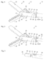
- FIG. 1 Figure 3 shows a schematic axonometric view of a distal end 12 of a medical instrument 10 for microinvasive human or veterinary medical applications.
- the medical instrument 10 has a long, thin, rigid or flexible (ie elastically or non-destructively plastically deformable) straight or curved shaft 20.
- the distal of the shaft 20 is connected to a tool 30, in particular with its proximal end 34 non-destructively releasably mechanically connected.
- proximal end of the shaft 20 may be provided a handling device for manual handling of the medical instrument 10.
- the tool 30 comprises two sectors 32, which can be pivoted in opposite directions about the same pivot axis, for gripping, squeezing, electrosurgical coagulation or cutting of tissue.
- the tool 30 comprises a first component or fork component 40 and a second component or lug component 50.
- the fork component 40 comprises two parallel spars 41 whose distal ends 42 form the distal end of the fork component 40.
- a bearing 43 for the pivotable branches 32 is provided at the distal ends 42 of the spars 41.
- the bearing 43 is formed by a shaft connecting the distal ends 42 of the spars 41.
- the shaft defines the common pivot axis of the pivotal branches 32.
- the proximal end of the fork member 40 is formed by a substantially circular proximal edge 44 of the fork member 40.
- the proximal edge 44 of the fork member 40 is interrupted by two oppositely disposed slots 48, of which in FIG. 1 only one is visible.
- the slots 48 each have a substantially rectangular shape.
- the lug component 50 comprises an annular region 54, which is arranged parallel to the proximal edge 44 of the fork component 40 and can be joined thereto, in particular connected by welding.
- the lug component 50 further comprises two opposing lugs, the radially outer ends or regions 58 of which fill the slots 48 at the proximal end of the fork component 40 and are joined thereto.
- the edges of the radially outer regions 58 of the lugs of the lug component 50 are connected to the edges of the slots 48 by welding or soldering.
- a transmission device is arranged, which in the representation in FIG. 1 is largely hidden by the shaft 20 and the fork member 40 of the tool 30. Only one end piece 62 forming the distal end of the transmission device is in FIG. 1 between the spars 41 of the Fork member 40 of the tool 30 partially visible.
- the transfer device is displaceable within the shaft 20 and the fork member 40 of the tool 30 in the direction parallel to the longitudinal axis of the shaft 20 within a predetermined range.
- the proximal end of the transmission device is, for example, coupled to a pivotable part of the aforementioned handling device at the proximal end of the shaft 20.
- the end piece 62 forming the distal end of the transmission device is pivotably coupled to the branches 32 via a connecting rod 36 such that a translational movement of the transmission device is accompanied by a pivoting movement of the branches 32 of the tool 30.
- FIG. 2 shows a schematic axonometric view of the tool 30 from FIG. 1 .
- the type of representation, in particular the line of sight, largely corresponds to that of FIG. 1 ,
- FIG. 2 only the tool 30 is shown, not the stem 20 of the medical instrument. That is why in FIG. 2 a further part of the transfer device 60 visible, namely a rod 70, which for placement in the shaft 20 of the medical instrument 10 (see. FIG. 1 ) is provided.
- FIG. 2 the annular structure of the annular portion 54 and a cavity 46 in the fork member 40 recognizable.
- FIG. 3 2 shows a schematic axonometric view of components of the shaft 20 of the medical instrument 10 FIG. 1 .
- the type of representation, in particular the line of sight, largely corresponds to that of Figures 1 and 2 ,
- the shaft comprises a shaft tube 24 whose position in FIG. 3 in the horizontal direction of the position in FIG. 1 equivalent.
- a shaft tube 24 whose position in FIG. 3 in the horizontal direction of the position in FIG. 1 equivalent.
- At the distal end 22 of the shaft tube 24 are provided two oppositely disposed, each L-shaped slots, of which in FIG. 3 only one is visible.
- Each L-shaped slot includes a first portion 25 extending parallel to the longitudinal axis 28 of the shaft tube 24 and a second portion 26 extending in a direction parallel to the circumference of the shaft tube 24.
- a support tube 80 is shown, which is arranged in the finished and used in the intended manner shaft at the distal end 22 of the shaft within the shaft tube 24.
- the support tube 80 is in FIG. 3 outside the shaft tube 24, namely in the direction parallel to the longitudinal axis 28 of the shaft pulled out of the shaft tube 24 distally shown.
- the support tube 80 is arranged in particular in the shaft tube 24 such that the distal edge of the support tube 80 and the distal edge of the shaft tube 24 lie in one plane.
- the support tube 80 has two straight, respectively rectangular or substantially rectangular and opposing slots 86, of which in FIG. 3 only one is visible.
- the slots 86 are parallel to the longitudinal axis 28 of the shaft and thus also parallel to the intended direction of movement of the transmission device 60 (see. FIG. 2 ).
- the support tube 80 reinforces the distal end 22 of the shaft.
- the inner cross section of the support tube 80 (apart from the slots 86) substantially corresponds to the outer cross section of the rod 70 of the transfer device 60 (see FIG. FIG. 2 ), so that the transmission device 60 is performed in the support tube 80 play and friction.
- the outer cross section of the shaft tube 24 and thus the shaft at the distal end 22 (apart from the L-shaped slots 25, 26) corresponds to the cross section of the cavity 46 (apart from the lugs) at the proximal end of the fork member 40 (see. Figures 2 . 5, 6 ), so that the distal end 22 of the shaft 20 in the cavity 46 in the fork member 40 is guided with low backlash.
- FIG. 4 shows a further schematic axonometric representation of parts of the tool 30 from FIG. 2 .
- the type of representation, in particular the line of sight, largely corresponds to that of Figures 1 and 2 ,
- FIG. 4 the tool 30 is shown without the lug component 50. Therefore, the slots 48 in the fork member 40 which extend from and interrupt the substantially circular proximal edge 44 of the fork member 40 are visible.
- FIG. 5 shows a further schematic axonometric representation of the tool 30 from the Figures 2 and 4 .
- the type of representation, in particular the line of sight, largely corresponds to that of FIGS. 1, 2 and 4 ,
- the fork member 40 of the tool 30 is shown transparent and indicated only by its visible in the selected direction of contours contours. That's why in FIG. 5 the lugs 56 are visible distally of the annular region 54 of the lug component 50, whose outer ends or regions 58, the slots 48 in the fork member 40 (see. FIG. 4 ) fill out. The radially inner ends of the lugs 56 extend into the cavity 46 at the proximal end of the fork member 40 (see FIG. FIG. 4 ).
- the transfer device 60 comprises a rod 70 and an end piece 62, which forms the distal end of the transfer device 60.
- the end piece 62 includes a distal end 64 having a bearing for hinged connection with the connecting rods 36 and a substantially thin and plate-shaped proximal end 66 disposed in a slot at the distal end 72 of the rod 70. From the slot at the distal end 72 of the rod 70 laterally projecting edges of the thin plate-shaped proximal end 66 of the end piece 62 form two web-shaped locking projections 68.
- the locking projections 68 each extend parallel to the longitudinal axis of the rod 70 of the transfer device 60 and thus also parallel to the longitudinal axis 28 of the shaft 20 (see. FIG. 3 ) and to the slots 86 in the support tube 80th
- FIG. 6 shows a schematic representation of the gudgeon member 50 in a view of distal.
- the contour of the cross section of the rod 70 of the transmission device 60 indicated.
- the inner contour of the annular region 54 of the lug component 50 corresponds to the contour of the cross section of the cavity 46 at the proximal end of the fork component 40 (cf. Figures 2 . 4 ).
- the lugs 56 engage in the cavity 46 from the outside.
- the widths of the lugs 56 correspond to the widths of the first portions 25 of the L-shaped slots in the shank tube 24, so that the lugs can be passed through the first sections 25 of the L-shaped slots in the shaft tube 24 in a friction-free manner. If the lugs 56 engage so deep in the cavity 46 that they also in the slots 86 in the support tube 80 (see. FIG. 3 ), the slots 86 in the support tube 80 are at least as wide as the lugs 56 and deviating from the illustration in FIG FIG. 3 L-shaped.
- the lengths of the lugs correspond to the dimensions of the second portions 26 of the L-shaped slots in the shaft tube 24, so that the lugs 56 can be inserted with low friction into the second portions 26 of the L-shaped slots.
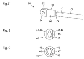
- FIG. 7 shows a further schematic axonometric representation of components of the transfer device 60 of the tool 30 from the Figures 1 and 2 ,
- the end member 62 is in FIG. 7 shown displaced distally relative to the rod 70. That's why in FIG. 7 the slot 74 on the distal end 72 of the rod 70 on the one hand and the thin plate-shaped proximal end 66 of the end piece 62 on the other hand clearly visible.
- the lateral or parallel to the longitudinal axis of the rod 70 extending edges of the proximal end 66 of the end piece 62 form the locking projections 68.
- the locking projections 68 have rounded cross-sections.
- FIG. 8 shows a schematic representation of the fork member 40 of the tool 30 from the Figures 1 and 2 in a view from distal.
- the fork member 40 has between the proximal ends of the spars 41 on the one hand and the distal end of the cavity 46 (see. FIG. 4 On the other hand, a wall 45, which is not visible in the other figures. In particular, this wall 45 is substantially plate-shaped and planar and defines the cavity 46 distally or forms the distal surface of the cavity 46.
- a through hole 47 is provided in the wall 45.
- the through hole 47 extends in the axial direction of the fork member 40 and thus in the direction orthogonal to the plane of the drawing FIG. 9 from the space between the spars 41 on the one hand to the cavity 46 at the proximal end of the fork member 40 (see. Figures 2 . 4 ), which is in FIG. 9 is not visible, on the other hand.
- the through-bore 47 has a cross-section which largely corresponds to the cross-section of the transfer device 60 in the transition region between the end piece 62 and the rod 70 (see FIG. Figures 5 . 7 ), so that the transmission device 60 in the through hole 47 in the fork member 40 play and low friction is performed.
- the cross-section of the transfer device 60 in the transition region between the end piece 62 and the rod 70 (see. Figures 5 . 7 ) and the cross section of the through hole 47 are each not circular.
- the cross section of the transmission device 60 deviates from the locking projections 68 (cf. Figures 5 ) from a pure circular shape. As a result, a rotation of the transmission device 60 is positively locked relative to the fork member 40.
- FIG. 9 shows a further schematic representation of the fork member 40 of the tool 30 from the Figures 1 and 2 ,
- a view of the fork member 40 is shown from proximal.
- the fork member 40 in the FIGS. 8 and 9 shown from opposite directions.
- FIG. 9 In FIG. 9 are the through hole 47, the substantially circular cylindrical cavity 46 at the proximal end of the fork member 40 and the two opposing slots 48 in the fork member 40 visible.
- the transfer device 60 by positive engagement between the transition region between the rod 70 and the end piece 62, in particular the locking projections 68, on the one hand (see. Figures 5 . 7 ) and the through hole 47 in the fork member 40 on the other hand so in the fork member 40 (see. FIGS. 8, 9 ) is guided, that the transmission device 60 relative to the fork member 40, although displaced in the longitudinal direction, but can not be rotated.
- a similar guide by positive engagement between the connecting rods 36, the distal end 64 of the end piece 62 of the transmission device 60 and the facing surfaces of the spars 41 of the fork member 40 (see. Figures 2 . 4 ) be achieved.
- the transmission device 60 for the releasable mechanical connection of the tool 30 to the shaft 20, the transmission device 60, in particular the rod 70 of the transmission device 60 (cf. FIG. 2 ), from distal into the shaft 20 (cf. FIG. 3 ) introduced.
- the branches 32 of the tool 30 are brought into an overtight position, in which the angle between the branches 32 is greater than in the FIGS. 1, 2 . 4 and 5 is shown.
- the locking projections 68 on the transfer device 60 assume their extremely distal position, in which they engage in the through hole 47 in the fork member 40, but do not protrude into the cavity 46 at the proximal end of the fork member 40.
- the shaft 20 and the tool 30 are brought together so far that the distal end 22 of the shaft 20 is fully inserted into the cavity 46 in the fork member 40 of the tool 30 and the distal end 22 of the shaft 20 abuts the wall 45 of the fork member 40.
- the lugs 56 are inserted into the first portions 25 of the L-shaped slots at the distal end 22 of the shaft 20.
- the lugs 56 are in the transition regions between the first portions 25 and the second portions 26 of the L-shaped slots at the distal end 22 of the shaft tube 24 (see. FIG. 3 ).
- the shaft 20 can now be rotated relative to the tool 30 about its axis 28 in a clockwise direction (viewed from proximal).
- the lugs 56 are moved away from the first portions 25 into the second portions 26 of the L-shaped slots at the distal end 22 of the shaft 20.
- the shank 20 and tool 30 are in their intended relative positions, in which shank 20 and tool 30 can not be separated from each other by a simple translational movement.
- the locking projections 68 on the transmission device 60 are aligned (see. FIG. 5 ) with the slots 86 in the support tube 80 and the first portions 25 of the L-shaped slots at the distal end 22 of the shaft tube 24 (see. FIG. 3 ).
- the transfer device 60 can therefore be moved proximally relative to the tool 30 and the shaft 20, with the branches 32 leaving their over-exposed position.
- the locking projections 68 engage the transmission device 60 in the slots 86 in the support tube 80 and the first portions 25 of the L-shaped slots in the shaft tube 24 a.
- the tool 30 can no longer be rotated relative to the shaft 20 and the lugs 56 can not be moved to the first portions 25 of the L-shaped slots in the shaft tube 24.
- the mechanical connection between the shaft 20 and tool 30 is locked as long as the branches 32 are not in their overtop position.
- the distal edge or the distal end 22 of the shaft tube 24 on the wall 45 in the fork member 40 (see. FIGS. 8, 9 ) and on the other hand, the distal ends or edges of the lugs 56 (see. FIG. 5 ) at the distal edges of the second portions 26 of the L-shaped slots in the steerer tube 24 (see FIG. FIG. 3 ) at.
- a longitudinal clearance of the mechanical connection between shaft 20 and tool 30 is determined by the difference between the distance of the distal edges or flanks of the lugs 56 (see FIG. FIG. 5 ) and the wall 45 in the fork member 40 (see. FIGS. 8, 9 ) on the one hand and the distance between the distal edges of the second portions 26 of the L-shaped slots in the shaft tube 24 and the distal end 22 of the shaft tube 24 on the other hand defined.
- the mechanical clearance between shaft 20 and tool 30 defining distances are thus defined in each case on a single component.
- this is the distance between the distal edge or end 22 of the shaft tube 24 and the distal edge of the second portion 26 of the L-shaped slot in the shaft tube 24.
- On the tool this is the distance between the proximal surface of the wall 45 in the fork component 40 and the distal ends of the slots 48 in the yoke member against which abut the distal end surfaces of the outer portions 58 of the lugs 56.
- a blockage of the over-exposed position on the handling device is possibly first of all released. Thereafter, the branches 32 are moved to their overtop position and the transfer device 60 with the locking projections 68 in its extremely distal position. In this configuration, the locking protrusions 68 engage the transfer device 60 (see FIG. FIG. 5 ) no longer in the slots 86 in the support tube 80 and in the first portions 25 of the L-shaped slots in the shaft tube 24 (see Figure).
- the tool 30 may be rotated counterclockwise relative to the shaft 20 (as viewed distally).
- the externally engaging lugs 56 are moved in the second portions 26 to the transition areas between the second portions 26 and the first portions 25 of the L-shaped slots in the shaft tube 24. Thereafter, shank 20 and tool 30 can be pulled apart. The lugs 56 are moved in the first portions 25 of the L-shaped slots in the shaft tube 24 and pulled out of this.
Landscapes
- Health & Medical Sciences (AREA)
- Surgery (AREA)
- Life Sciences & Earth Sciences (AREA)
- Medical Informatics (AREA)
- Animal Behavior & Ethology (AREA)
- Engineering & Computer Science (AREA)
- Biomedical Technology (AREA)
- Heart & Thoracic Surgery (AREA)
- Veterinary Medicine (AREA)
- Molecular Biology (AREA)
- Nuclear Medicine, Radiotherapy & Molecular Imaging (AREA)
- General Health & Medical Sciences (AREA)
- Public Health (AREA)
- Ophthalmology & Optometry (AREA)
- Oral & Maxillofacial Surgery (AREA)
- Pathology (AREA)
- Surgical Instruments (AREA)
Applications Claiming Priority (1)
| Application Number | Priority Date | Filing Date | Title |
|---|---|---|---|
| DE102015108219.5A DE102015108219A1 (de) | 2015-05-26 | 2015-05-26 | Werkzeug für ein zerlegbares medizinisches Instrument |
Publications (2)
| Publication Number | Publication Date |
|---|---|
| EP3097873A1 true EP3097873A1 (fr) | 2016-11-30 |
| EP3097873B1 EP3097873B1 (fr) | 2019-11-13 |
Family
ID=55754203
Family Applications (1)
| Application Number | Title | Priority Date | Filing Date |
|---|---|---|---|
| EP16165351.4A Active EP3097873B1 (fr) | 2015-05-26 | 2016-04-14 | Outil pour un instrument medical demontable |
Country Status (3)
| Country | Link |
|---|---|
| US (1) | US10206756B2 (fr) |
| EP (1) | EP3097873B1 (fr) |
| DE (1) | DE102015108219A1 (fr) |
Families Citing this family (4)
| Publication number | Priority date | Publication date | Assignee | Title |
|---|---|---|---|---|
| DE102017128601A1 (de) | 2017-12-01 | 2019-06-06 | Technische Universität Darmstadt | Wellenkupplungsmechanismus zum Ein- und Auskuppeln mittels den gegebenen Freiheitsgraden Translation und Rotation |
| DE102019121036A1 (de) * | 2019-08-05 | 2021-02-11 | Karl Storz Se & Co. Kg | Endoskopische Vorrichtung |
| DE102020103412A1 (de) * | 2020-02-11 | 2021-08-12 | Karl Storz Se & Co. Kg | Endoskopische Vorrichtung |
| DE102022116385A1 (de) | 2022-06-30 | 2024-01-04 | Karl Storz Se & Co. Kg | Kopplungsvorrichtung für ein zerlegbares chirurgisches instrument und verfahren zur betätigung der kopplungsvorrichtung |
Citations (3)
| Publication number | Priority date | Publication date | Assignee | Title |
|---|---|---|---|---|
| WO2010114634A1 (fr) * | 2009-04-03 | 2010-10-07 | The Board Of Trustees Of The Leland Stanford Junior University | Dispositif et procédé chirurgicaux |
| EP2653110A1 (fr) * | 2012-04-18 | 2013-10-23 | Karl Storz GmbH & Co. KG | Instrument médical doté d'une tige pliable |
| EP2653123A1 (fr) * | 2012-04-18 | 2013-10-23 | Karl Storz GmbH & Co. KG | Outil pour un instrument médical |
Family Cites Families (2)
| Publication number | Priority date | Publication date | Assignee | Title |
|---|---|---|---|---|
| DE102011007122A1 (de) * | 2011-04-11 | 2012-10-11 | Karl Storz Gmbh & Co. Kg | Werkzeug für ein mikroinvasiv-chirurgisches Instrument |
| DE102013211368B4 (de) * | 2013-06-18 | 2024-02-22 | Richard Wolf Gmbh | Endoskopisches Schaftinstrument |
-
2015
- 2015-05-26 DE DE102015108219.5A patent/DE102015108219A1/de not_active Withdrawn
-
2016
- 2016-04-14 EP EP16165351.4A patent/EP3097873B1/fr active Active
- 2016-05-26 US US15/164,942 patent/US10206756B2/en active Active
Patent Citations (3)
| Publication number | Priority date | Publication date | Assignee | Title |
|---|---|---|---|---|
| WO2010114634A1 (fr) * | 2009-04-03 | 2010-10-07 | The Board Of Trustees Of The Leland Stanford Junior University | Dispositif et procédé chirurgicaux |
| EP2653110A1 (fr) * | 2012-04-18 | 2013-10-23 | Karl Storz GmbH & Co. KG | Instrument médical doté d'une tige pliable |
| EP2653123A1 (fr) * | 2012-04-18 | 2013-10-23 | Karl Storz GmbH & Co. KG | Outil pour un instrument médical |
Also Published As
| Publication number | Publication date |
|---|---|
| US10206756B2 (en) | 2019-02-19 |
| DE102015108219A1 (de) | 2016-12-01 |
| US20160346057A1 (en) | 2016-12-01 |
| EP3097873B1 (fr) | 2019-11-13 |
Similar Documents
| Publication | Publication Date | Title |
|---|---|---|
| EP2696741B1 (fr) | Dispositif de commande | |
| EP3528688B1 (fr) | Dispositif médical | |
| EP0118778B1 (fr) | Clou d'ancrage | |
| DE102009042490A1 (de) | Steuerungsvorrichtung | |
| EP3000404B1 (fr) | Instrument medical et dispositif de liaison destine a relier deux composants d'un instrument medical | |
| EP2434939A1 (fr) | Dispositif de commande | |
| EP3097873B1 (fr) | Outil pour un instrument medical demontable | |
| EP3261566B1 (fr) | Plaque d'ostéosynthèse et kit chirurgical pour la fixation de fragments osseux | |
| DE202011000848U1 (de) | Steuerungsvorrichtung | |
| EP2653117B1 (fr) | Accouplement entre deux parties d'un instrument médical | |
| EP3135183B1 (fr) | Instrument medical micro-invasif | |
| EP4574010A1 (fr) | Articulation pour un mécanisme de déviation ou dans un mécanisme de déviation | |
| DE202016100245U1 (de) | Chirurgische Führungshilfe und chirurgisches Bohrset | |
| EP3300675B1 (fr) | Composants pour un instrument médical et instrument médical | |
| WO2017021469A1 (fr) | Instrument de préhension pour un ancrage osseux | |
| EP2258285B1 (fr) | Poinçonneuse médicale | |
| WO2002080790A1 (fr) | Broche a usage chirurgical | |
| DE202007000427U1 (de) | Chirurgischer Haltegriff und chirurgisches Instrument | |
| DE102024134412B3 (de) | Chirurgisches Maulteilwerkzeug, chirurgisches Instrument und Herstellungsverfahren | |
| DE102013003316B4 (de) | Chirurgisches Maulinstrument | |
| DE4444025A1 (de) | Betätigungselement für medizinische Zangen | |
| DE20106723U1 (de) | Modular aufgebaute Knochenraspel oder Modular aufgebautes Schaftimplantat | |
| DE102013211368A1 (de) | Endoskopisches Schaftinstrument | |
| EP3231380B1 (fr) | Outil pour un instrument médical et instrument médical | |
| EP3178419B1 (fr) | Dispositif d'accouplement pour un instrument médical démontable |
Legal Events
| Date | Code | Title | Description |
|---|---|---|---|
| PUAI | Public reference made under article 153(3) epc to a published international application that has entered the european phase |
Free format text: ORIGINAL CODE: 0009012 |
|
| AK | Designated contracting states |
Kind code of ref document: A1 Designated state(s): AL AT BE BG CH CY CZ DE DK EE ES FI FR GB GR HR HU IE IS IT LI LT LU LV MC MK MT NL NO PL PT RO RS SE SI SK SM TR |
|
| AX | Request for extension of the european patent |
Extension state: BA ME |
|
| STAA | Information on the status of an ep patent application or granted ep patent |
Free format text: STATUS: REQUEST FOR EXAMINATION WAS MADE |
|
| 17P | Request for examination filed |
Effective date: 20170530 |
|
| RBV | Designated contracting states (corrected) |
Designated state(s): AL AT BE BG CH CY CZ DE DK EE ES FI FR GB GR HR HU IE IS IT LI LT LU LV MC MK MT NL NO PL PT RO RS SE SI SK SM TR |
|
| STAA | Information on the status of an ep patent application or granted ep patent |
Free format text: STATUS: EXAMINATION IS IN PROGRESS |
|
| 17Q | First examination report despatched |
Effective date: 20171102 |
|
| RAP1 | Party data changed (applicant data changed or rights of an application transferred) |
Owner name: KARL STORZ SE & CO. KG |
|
| GRAP | Despatch of communication of intention to grant a patent |
Free format text: ORIGINAL CODE: EPIDOSNIGR1 |
|
| STAA | Information on the status of an ep patent application or granted ep patent |
Free format text: STATUS: GRANT OF PATENT IS INTENDED |
|
| INTG | Intention to grant announced |
Effective date: 20190906 |
|
| RIN1 | Information on inventor provided before grant (corrected) |
Inventor name: KAERCHER, DANIEL Inventor name: STEFAN, JOCHEN |
|
| GRAS | Grant fee paid |
Free format text: ORIGINAL CODE: EPIDOSNIGR3 |
|
| GRAA | (expected) grant |
Free format text: ORIGINAL CODE: 0009210 |
|
| STAA | Information on the status of an ep patent application or granted ep patent |
Free format text: STATUS: THE PATENT HAS BEEN GRANTED |
|
| AK | Designated contracting states |
Kind code of ref document: B1 Designated state(s): AL AT BE BG CH CY CZ DE DK EE ES FI FR GB GR HR HU IE IS IT LI LT LU LV MC MK MT NL NO PL PT RO RS SE SI SK SM TR |
|
| REG | Reference to a national code |
Ref country code: CH Ref legal event code: EP Ref country code: AT Ref legal event code: REF Ref document number: 1200855 Country of ref document: AT Kind code of ref document: T Effective date: 20191115 |
|
| REG | Reference to a national code |
Ref country code: DE Ref legal event code: R096 Ref document number: 502016007525 Country of ref document: DE |
|
| REG | Reference to a national code |
Ref country code: IE Ref legal event code: FG4D Free format text: LANGUAGE OF EP DOCUMENT: GERMAN |
|
| REG | Reference to a national code |
Ref country code: NL Ref legal event code: MP Effective date: 20191113 |
|
| REG | Reference to a national code |
Ref country code: LT Ref legal event code: MG4D |
|
| PG25 | Lapsed in a contracting state [announced via postgrant information from national office to epo] |
Ref country code: BG Free format text: LAPSE BECAUSE OF FAILURE TO SUBMIT A TRANSLATION OF THE DESCRIPTION OR TO PAY THE FEE WITHIN THE PRESCRIBED TIME-LIMIT Effective date: 20200213 Ref country code: GR Free format text: LAPSE BECAUSE OF FAILURE TO SUBMIT A TRANSLATION OF THE DESCRIPTION OR TO PAY THE FEE WITHIN THE PRESCRIBED TIME-LIMIT Effective date: 20200214 Ref country code: NO Free format text: LAPSE BECAUSE OF FAILURE TO SUBMIT A TRANSLATION OF THE DESCRIPTION OR TO PAY THE FEE WITHIN THE PRESCRIBED TIME-LIMIT Effective date: 20200213 Ref country code: SE Free format text: LAPSE BECAUSE OF FAILURE TO SUBMIT A TRANSLATION OF THE DESCRIPTION OR TO PAY THE FEE WITHIN THE PRESCRIBED TIME-LIMIT Effective date: 20191113 Ref country code: FI Free format text: LAPSE BECAUSE OF FAILURE TO SUBMIT A TRANSLATION OF THE DESCRIPTION OR TO PAY THE FEE WITHIN THE PRESCRIBED TIME-LIMIT Effective date: 20191113 Ref country code: LV Free format text: LAPSE BECAUSE OF FAILURE TO SUBMIT A TRANSLATION OF THE DESCRIPTION OR TO PAY THE FEE WITHIN THE PRESCRIBED TIME-LIMIT Effective date: 20191113 Ref country code: PT Free format text: LAPSE BECAUSE OF FAILURE TO SUBMIT A TRANSLATION OF THE DESCRIPTION OR TO PAY THE FEE WITHIN THE PRESCRIBED TIME-LIMIT Effective date: 20200313 Ref country code: NL Free format text: LAPSE BECAUSE OF FAILURE TO SUBMIT A TRANSLATION OF THE DESCRIPTION OR TO PAY THE FEE WITHIN THE PRESCRIBED TIME-LIMIT Effective date: 20191113 Ref country code: PL Free format text: LAPSE BECAUSE OF FAILURE TO SUBMIT A TRANSLATION OF THE DESCRIPTION OR TO PAY THE FEE WITHIN THE PRESCRIBED TIME-LIMIT Effective date: 20191113 Ref country code: LT Free format text: LAPSE BECAUSE OF FAILURE TO SUBMIT A TRANSLATION OF THE DESCRIPTION OR TO PAY THE FEE WITHIN THE PRESCRIBED TIME-LIMIT Effective date: 20191113 |
|
| PG25 | Lapsed in a contracting state [announced via postgrant information from national office to epo] |
Ref country code: IS Free format text: LAPSE BECAUSE OF FAILURE TO SUBMIT A TRANSLATION OF THE DESCRIPTION OR TO PAY THE FEE WITHIN THE PRESCRIBED TIME-LIMIT Effective date: 20200313 Ref country code: HR Free format text: LAPSE BECAUSE OF FAILURE TO SUBMIT A TRANSLATION OF THE DESCRIPTION OR TO PAY THE FEE WITHIN THE PRESCRIBED TIME-LIMIT Effective date: 20191113 Ref country code: RS Free format text: LAPSE BECAUSE OF FAILURE TO SUBMIT A TRANSLATION OF THE DESCRIPTION OR TO PAY THE FEE WITHIN THE PRESCRIBED TIME-LIMIT Effective date: 20191113 |
|
| PG25 | Lapsed in a contracting state [announced via postgrant information from national office to epo] |
Ref country code: AL Free format text: LAPSE BECAUSE OF FAILURE TO SUBMIT A TRANSLATION OF THE DESCRIPTION OR TO PAY THE FEE WITHIN THE PRESCRIBED TIME-LIMIT Effective date: 20191113 |
|
| PG25 | Lapsed in a contracting state [announced via postgrant information from national office to epo] |
Ref country code: ES Free format text: LAPSE BECAUSE OF FAILURE TO SUBMIT A TRANSLATION OF THE DESCRIPTION OR TO PAY THE FEE WITHIN THE PRESCRIBED TIME-LIMIT Effective date: 20191113 Ref country code: DK Free format text: LAPSE BECAUSE OF FAILURE TO SUBMIT A TRANSLATION OF THE DESCRIPTION OR TO PAY THE FEE WITHIN THE PRESCRIBED TIME-LIMIT Effective date: 20191113 Ref country code: EE Free format text: LAPSE BECAUSE OF FAILURE TO SUBMIT A TRANSLATION OF THE DESCRIPTION OR TO PAY THE FEE WITHIN THE PRESCRIBED TIME-LIMIT Effective date: 20191113 Ref country code: CZ Free format text: LAPSE BECAUSE OF FAILURE TO SUBMIT A TRANSLATION OF THE DESCRIPTION OR TO PAY THE FEE WITHIN THE PRESCRIBED TIME-LIMIT Effective date: 20191113 Ref country code: RO Free format text: LAPSE BECAUSE OF FAILURE TO SUBMIT A TRANSLATION OF THE DESCRIPTION OR TO PAY THE FEE WITHIN THE PRESCRIBED TIME-LIMIT Effective date: 20191113 |
|
| REG | Reference to a national code |
Ref country code: DE Ref legal event code: R097 Ref document number: 502016007525 Country of ref document: DE |
|
| PG25 | Lapsed in a contracting state [announced via postgrant information from national office to epo] |
Ref country code: SM Free format text: LAPSE BECAUSE OF FAILURE TO SUBMIT A TRANSLATION OF THE DESCRIPTION OR TO PAY THE FEE WITHIN THE PRESCRIBED TIME-LIMIT Effective date: 20191113 Ref country code: SK Free format text: LAPSE BECAUSE OF FAILURE TO SUBMIT A TRANSLATION OF THE DESCRIPTION OR TO PAY THE FEE WITHIN THE PRESCRIBED TIME-LIMIT Effective date: 20191113 |
|
| PLBE | No opposition filed within time limit |
Free format text: ORIGINAL CODE: 0009261 |
|
| STAA | Information on the status of an ep patent application or granted ep patent |
Free format text: STATUS: NO OPPOSITION FILED WITHIN TIME LIMIT |
|
| 26N | No opposition filed |
Effective date: 20200814 |
|
| PG25 | Lapsed in a contracting state [announced via postgrant information from national office to epo] |
Ref country code: SI Free format text: LAPSE BECAUSE OF FAILURE TO SUBMIT A TRANSLATION OF THE DESCRIPTION OR TO PAY THE FEE WITHIN THE PRESCRIBED TIME-LIMIT Effective date: 20191113 Ref country code: MC Free format text: LAPSE BECAUSE OF FAILURE TO SUBMIT A TRANSLATION OF THE DESCRIPTION OR TO PAY THE FEE WITHIN THE PRESCRIBED TIME-LIMIT Effective date: 20191113 |
|
| REG | Reference to a national code |
Ref country code: CH Ref legal event code: PL |
|
| PG25 | Lapsed in a contracting state [announced via postgrant information from national office to epo] |
Ref country code: LI Free format text: LAPSE BECAUSE OF NON-PAYMENT OF DUE FEES Effective date: 20200430 Ref country code: CH Free format text: LAPSE BECAUSE OF NON-PAYMENT OF DUE FEES Effective date: 20200430 Ref country code: LU Free format text: LAPSE BECAUSE OF NON-PAYMENT OF DUE FEES Effective date: 20200414 |
|
| REG | Reference to a national code |
Ref country code: BE Ref legal event code: MM Effective date: 20200430 |
|
| PG25 | Lapsed in a contracting state [announced via postgrant information from national office to epo] |
Ref country code: BE Free format text: LAPSE BECAUSE OF NON-PAYMENT OF DUE FEES Effective date: 20200430 |
|
| PG25 | Lapsed in a contracting state [announced via postgrant information from national office to epo] |
Ref country code: IE Free format text: LAPSE BECAUSE OF NON-PAYMENT OF DUE FEES Effective date: 20200414 |
|
| PG25 | Lapsed in a contracting state [announced via postgrant information from national office to epo] |
Ref country code: TR Free format text: LAPSE BECAUSE OF FAILURE TO SUBMIT A TRANSLATION OF THE DESCRIPTION OR TO PAY THE FEE WITHIN THE PRESCRIBED TIME-LIMIT Effective date: 20191113 Ref country code: MT Free format text: LAPSE BECAUSE OF FAILURE TO SUBMIT A TRANSLATION OF THE DESCRIPTION OR TO PAY THE FEE WITHIN THE PRESCRIBED TIME-LIMIT Effective date: 20191113 Ref country code: CY Free format text: LAPSE BECAUSE OF FAILURE TO SUBMIT A TRANSLATION OF THE DESCRIPTION OR TO PAY THE FEE WITHIN THE PRESCRIBED TIME-LIMIT Effective date: 20191113 |
|
| REG | Reference to a national code |
Ref country code: AT Ref legal event code: MM01 Ref document number: 1200855 Country of ref document: AT Kind code of ref document: T Effective date: 20210414 |
|
| PG25 | Lapsed in a contracting state [announced via postgrant information from national office to epo] |
Ref country code: MK Free format text: LAPSE BECAUSE OF FAILURE TO SUBMIT A TRANSLATION OF THE DESCRIPTION OR TO PAY THE FEE WITHIN THE PRESCRIBED TIME-LIMIT Effective date: 20191113 |
|
| PG25 | Lapsed in a contracting state [announced via postgrant information from national office to epo] |
Ref country code: AT Free format text: LAPSE BECAUSE OF NON-PAYMENT OF DUE FEES Effective date: 20210414 |
|
| P01 | Opt-out of the competence of the unified patent court (upc) registered |
Effective date: 20230527 |
|
| PGFP | Annual fee paid to national office [announced via postgrant information from national office to epo] |
Ref country code: DE Payment date: 20250428 Year of fee payment: 10 |
|
| PGFP | Annual fee paid to national office [announced via postgrant information from national office to epo] |
Ref country code: IT Payment date: 20250422 Year of fee payment: 10 |
|
| PGFP | Annual fee paid to national office [announced via postgrant information from national office to epo] |
Ref country code: FR Payment date: 20250424 Year of fee payment: 10 |
|
| PGFP | Annual fee paid to national office [announced via postgrant information from national office to epo] |
Ref country code: GB Payment date: 20260313 Year of fee payment: 11 |