EP4574010A1 - Articulation pour un mécanisme de déviation ou dans un mécanisme de déviation - Google Patents
Articulation pour un mécanisme de déviation ou dans un mécanisme de déviation Download PDFInfo
- Publication number
- EP4574010A1 EP4574010A1 EP24219560.0A EP24219560A EP4574010A1 EP 4574010 A1 EP4574010 A1 EP 4574010A1 EP 24219560 A EP24219560 A EP 24219560A EP 4574010 A1 EP4574010 A1 EP 4574010A1
- Authority
- EP
- European Patent Office
- Prior art keywords
- connecting section
- extension
- section
- deflection mechanism
- articulating member
- Prior art date
- Legal status (The legal status is an assumption and is not a legal conclusion. Google has not performed a legal analysis and makes no representation as to the accuracy of the status listed.)
- Pending
Links
Images


Classifications
-
- A—HUMAN NECESSITIES
- A61—MEDICAL OR VETERINARY SCIENCE; HYGIENE
- A61B—DIAGNOSIS; SURGERY; IDENTIFICATION
- A61B1/00—Instruments for performing medical examinations of the interior of cavities or tubes of the body by visual or photographical inspection, e.g. endoscopes; Illuminating arrangements therefor
- A61B1/00064—Constructional details of the endoscope body
- A61B1/0011—Manufacturing of endoscope parts
-
- A—HUMAN NECESSITIES
- A61—MEDICAL OR VETERINARY SCIENCE; HYGIENE
- A61B—DIAGNOSIS; SURGERY; IDENTIFICATION
- A61B1/00—Instruments for performing medical examinations of the interior of cavities or tubes of the body by visual or photographical inspection, e.g. endoscopes; Illuminating arrangements therefor
- A61B1/005—Flexible endoscopes
- A61B1/008—Articulations
-
- A—HUMAN NECESSITIES
- A61—MEDICAL OR VETERINARY SCIENCE; HYGIENE
- A61B—DIAGNOSIS; SURGERY; IDENTIFICATION
- A61B1/00—Instruments for performing medical examinations of the interior of cavities or tubes of the body by visual or photographical inspection, e.g. endoscopes; Illuminating arrangements therefor
- A61B1/005—Flexible endoscopes
- A61B1/0051—Flexible endoscopes with controlled bending of insertion part
- A61B1/0055—Constructional details of insertion parts, e.g. vertebral elements
-
- A—HUMAN NECESSITIES
- A61—MEDICAL OR VETERINARY SCIENCE; HYGIENE
- A61B—DIAGNOSIS; SURGERY; IDENTIFICATION
- A61B17/00—Surgical instruments, devices or methods
- A61B17/00234—Surgical instruments, devices or methods for minimally invasive surgery
-
- A—HUMAN NECESSITIES
- A61—MEDICAL OR VETERINARY SCIENCE; HYGIENE
- A61B—DIAGNOSIS; SURGERY; IDENTIFICATION
- A61B17/00—Surgical instruments, devices or methods
- A61B17/00234—Surgical instruments, devices or methods for minimally invasive surgery
- A61B2017/00292—Surgical instruments, devices or methods for minimally invasive surgery mounted on or guided by flexible, e.g. catheter-like, means
- A61B2017/003—Steerable
- A61B2017/00305—Constructional details of the flexible means
- A61B2017/00314—Separate linked members
-
- A—HUMAN NECESSITIES
- A61—MEDICAL OR VETERINARY SCIENCE; HYGIENE
- A61M—DEVICES FOR INTRODUCING MEDIA INTO, OR ONTO, THE BODY; DEVICES FOR TRANSDUCING BODY MEDIA OR FOR TAKING MEDIA FROM THE BODY; DEVICES FOR PRODUCING OR ENDING SLEEP OR STUPOR
- A61M25/00—Catheters; Hollow probes
- A61M25/01—Introducing, guiding, advancing, emplacing or holding catheters
- A61M25/0105—Steering means as part of the catheter or advancing means; Markers for positioning
- A61M25/0133—Tip steering devices
- A61M25/0138—Tip steering devices having flexible regions as a result of weakened outer material, e.g. slots, slits, cuts, joints or coils
Definitions
- the present invention relates to an articulating member for or in a deflection mechanism at a distal end of a surgical instrument. Furthermore, the invention relates to a deflection mechanism and a method for manufacturing a deflection mechanism.
- a deflection mechanism for endoscopic instruments serves to bend an attached tool or accessory, in particular a pair of forceps, scissors, clamp, laser fiber, or similar.
- the deflection mechanism therefore serves, on the one hand, to align the tool at a distal end of the surgical instrument, such as an endoscope.
- an imaging accessory, an illumination device, and/or a steering device in particular by means of steering devices such as pull wires or similar, can be guided using the deflection mechanism.
- the deflection mechanism can also be referred to as a deflection unit or articulation unit, which has a through-hole with a working channel through which the accessory is guided.
- the accessory such as forceps, scissors, clamps, laser fiber, or similar, is usually pushed through the working channel of the endoscopic instrument.
- a light and/or imaging unit can be permanently installed in the endoscopic instrument.
- the deflection mechanism is made of individual articulating elements that are connected to each other by hinges.
- the deflection or alignment of the deflection mechanism can be achieved using pull wires, which are also guided at least partially through the through-hole, particularly in separate openings.
- EP 1 604 607 A1 A deflection mechanism in which hinge-like connections are formed between individual articulation members, the individual articulation members being connected via a type of movable dovetail connection.
- a pin is aligned longitudinally along the articulation member and engages in a recess of an adjacent articulation member.
- the recess has a semicircular shape, allowing rotation of the articulation members relative to one another.
- such a connection requires high standards of dimensional accuracy and precision, as the hinge joint is only formed with the thickness of the wall of the articulation member, and the articulation mechanism itself already has a very small cross-section.
- the maximum rotational movement of the two members is limited by the size of the semicircular recess. Particularly large angles can hardly be implemented, as the remaining material thickness between the ends of the semicircular recess becomes very small as the circumference increases.
- this object is achieved by an articulation member having the features of patent claim 1, a deflection mechanism having the features of patent claim 11 and/or by a method having the features of patent claim 16.
- the idea underlying the present invention is to create an articulated connection of individual articulating members which is possible solely from the geometry of the articulating members themselves, i.e. in particular a geometry of axial end sections or edge regions of the articulating members.
- the base body is designed, in particular, as a tubular or sleeve-shaped element, which is open, in particular, at both end sections. This allows an axial through-opening to be formed along the longitudinal axis of the articulating member.
- the end sections preferably have a circular or elliptical cross-section. Other cross-sections are also conceivable.
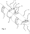
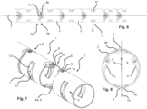
- a connecting section is arranged at at least one end section, which has an extension that is at least partially oriented in a radial direction of the base body.
- the extension can be oriented in the radial direction, so that a rotation axis or a joint axis can be formed that runs orthogonal to a longitudinal axis of the base body. Accordingly, the orientation of the joint axis can be influenced by the orientation of the extension.
- the extension can, for example, replace a rivet or a bolt, whereby the extension is advantageously connected to the base body as a single piece, for example, as a dome. This means that the extension is securely mounted to the base body from the outset, eliminating the need for a deflection mechanism during assembly.
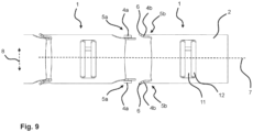
- the extension of the first connecting section engages with a connecting section of a second articulating member.
- the connecting sections of adjacent articulating members are, in particular, shaped to complement one another, so that the two connecting sections can anchor or hook onto one another.
- an articulated connection can be formed that enables rotation of adjacent articulating members relative to one another.
- a positive-locking and articulated connection between two articulating members enables the articulating members to be pivoted or rotated relative to one another.
- a rotation axis is defined, in particular, by the orientation of the extension.
- An extension is understood to be, in particular, a type of pin or hollow pin or a dome, which in particular has a round cross-section. This enables rotation of two articulating members relative to one another, wherein a connecting section of an adjacent articulating member can rotate around the extension.
- the extension is provided in particular on an outer surface of the base body and is in particular oriented outward in the radial direction. Likewise, the extension can be provided on an inner surface of the base body and in particular oriented inward in the radial direction.
- the articulating member is designed for or in a deflection mechanism of a surgical instrument, whereby any accessory, such as in particular a working channel for a tool such as forceps, scissors, laser fiber, retrieval basket, or the like, can be deflected or guided using the deflection mechanism. Furthermore, imaging, lighting, and/or steering, in particular by pull wires, as well as an irrigation, suction, and/or working channel, can be guided using the deflection mechanism.
- the multitude of accessories must be guided through the through-hole of the articulating member or the deflection mechanism. It is advantageous if the inner diameter of the through-hole is both continuously constant and as free of "obstructions" as possible. Especially with very Small diameters of the articulating members, such as diameters in the millimeter range, preferably less than or equal to 3 mm, therefore place high demands on the articulated connection between adjacent articulating members, so that these should be designed to save space.
- the proposed positive-locking and articulated connection offers the advantage that it hardly, or in particular not at all, engages in the inner cross-section of the base element. In particular, the protrusion of the connecting section into the interior of the base element is so small that the working channel is not disrupted.
- the articulating member therefore offers advantages in particular for particularly small diameters of the base body, especially in the millimeter range, preferably for diameters of 3 mm or smaller.
- the surgical instrument can be, in particular, an endoscopic instrument, preferably an endoscope.
- the articulating member is also suitable for other surgical instruments where miniaturization of the deflection mechanism is advantageous.
- a rivet-free connection between articulating members can be achieved, which can be achieved in particular solely through a positive fit between axial end sections.
- the articulating members can be easily plugged together, whereby a joint connection can be formed by elastically deforming at least one connecting section.
- the inventive design of articulating members is particularly suitable for single-use surgical instruments.
- so-called end links can be used at the end sections of the deflection mechanism, which have a connecting section only at one end section and are formed without a connecting section at the other end section.
- a second connecting section can be arranged at an axial second end section opposite the first end section, wherein the second connecting section is elastically designed so that a positive connection with a connecting section of a further articulating member can be established by elastic deflection.
- Elastic means in particular that the connecting section can be elastically deflected in two opposite directions so that the connecting section elastically deforms back into its original position when it is connected to the connecting section of an adjacent articulating member.
- the second connecting section can thus at least partially encompass the extension.
- the articulating member is therefore preferably formed from a metal and can in particular be produced by cutting it out of a tube.
- the second connecting section can be elastically deflected transversely to the radial direction and/or in the radial direction. This makes it possible for one connecting section to be pushed over another connecting section and to deform elastically back and forth in the process. If, for example, the second connecting section is to be pushed over the extension in order to then anchor itself to the extension, an elastic deflection in the radial direction that is designed to be self-restoring is advantageous. If the second connecting section is to be pushed past the extension, i.e. in particular to the side of the extension, in order to then encompass the extension like a type of clamp or fork, it is advantageous if the second connecting section is designed to be elastically transversely to the radial direction, i.e. in particular in a tangential direction.
- the second connecting portion may have a guide contour that is arranged on the connecting portion at an end facing away from the base body and enables a guided elastic deformation of the second connecting portion in the radial direction.
- the guide contour can be shaped as a kind of guide tab or wing which has a slope so that the second connecting section can be lifted more easily via the extension when two articulating members are connected to each other.
- the second connecting section can be fork-shaped, wherein the positive and articulated connection can be formed by encompassing the extension of another articulating member.
- Fork-shaped means in particular that the second connecting section has two legs, which are in particular mirrored to one another. With the two legs, the second connecting section can encompass the extension. If the legs are elastically shaped, in particular transverse to the radial direction, they can elastically deform back against the extension when they engage or snap into place around the extension. In particular, the recess between the two legs has an undercut so that the extension can be held in the undercut when the two articulating members are connected to one another. This can make it more difficult for the extension to be released from the second connecting section, although a rotational movement remains possible.
- the second connecting portion can have a recess complementary to the extension. This allows for aligned and centered mounting of the articulating members, thereby enabling the implementation of a defined deflection mechanism.
- two first connecting sections can be provided at the first end section.
- they can be formed, in particular, opposite one another in a cross-section of the first end section and/or mirrored to one another.
- a defined joint axis can be implemented between the two connecting sections.
Landscapes
- Health & Medical Sciences (AREA)
- Life Sciences & Earth Sciences (AREA)
- Surgery (AREA)
- Engineering & Computer Science (AREA)
- General Health & Medical Sciences (AREA)
- Biomedical Technology (AREA)
- Heart & Thoracic Surgery (AREA)
- Medical Informatics (AREA)
- Molecular Biology (AREA)
- Animal Behavior & Ethology (AREA)
- Nuclear Medicine, Radiotherapy & Molecular Imaging (AREA)
- Public Health (AREA)
- Veterinary Medicine (AREA)
- Pathology (AREA)
- Physics & Mathematics (AREA)
- Biophysics (AREA)
- Optics & Photonics (AREA)
- Radiology & Medical Imaging (AREA)
- Rehabilitation Therapy (AREA)
- Manufacturing & Machinery (AREA)
- Endoscopes (AREA)
Applications Claiming Priority (1)
| Application Number | Priority Date | Filing Date | Title |
|---|---|---|---|
| DE102023135983.5A DE102023135983A1 (de) | 2023-12-20 | 2023-12-20 | Artikulationsglied für eine oder in einer Auslenkmechanik |
Publications (1)
| Publication Number | Publication Date |
|---|---|
| EP4574010A1 true EP4574010A1 (fr) | 2025-06-25 |
Family
ID=93922836
Family Applications (1)
| Application Number | Title | Priority Date | Filing Date |
|---|---|---|---|
| EP24219560.0A Pending EP4574010A1 (fr) | 2023-12-20 | 2024-12-12 | Articulation pour un mécanisme de déviation ou dans un mécanisme de déviation |
Country Status (3)
| Country | Link |
|---|---|
| US (1) | US20250204758A1 (fr) |
| EP (1) | EP4574010A1 (fr) |
| DE (1) | DE102023135983A1 (fr) |
Families Citing this family (1)
| Publication number | Priority date | Publication date | Assignee | Title |
|---|---|---|---|---|
| US20260002617A1 (en) * | 2024-07-01 | 2026-01-01 | Fortimedix Assets Ii B.V. | Method of manufacturing a tube with a playless hinge and device comprising such a tube |
Citations (7)
| Publication number | Priority date | Publication date | Assignee | Title |
|---|---|---|---|---|
| EP0626604A2 (fr) * | 1993-05-28 | 1994-11-30 | CARL HAAS GmbH & CO. | Tube endoscopique flexible |
| EP1604607A1 (fr) | 2004-06-08 | 2005-12-14 | Henke-Sass, Wolf GmbH | Partie flexible d'un tube d'introduction d'un endoscope et procédé de fabrication |
| US20180093070A1 (en) * | 2016-10-05 | 2018-04-05 | Orbusneich Medical, Inc. | Modular Vascular Catheter |
| DE202018102207U1 (de) * | 2018-01-02 | 2018-04-26 | Zhuhai Kaden Medical Imaging Technology Co., Ltd. | Biegeabschnitt für ein Einwegendoskop |
| CN208355432U (zh) * | 2017-08-22 | 2019-01-11 | 圻逸科技股份有限公司 | 内视镜可弯曲导管构造 |
| US20200205908A1 (en) * | 2018-12-28 | 2020-07-02 | Auris Health, Inc. | Medical instrument with articulable segment |
| WO2023041377A1 (fr) * | 2021-09-14 | 2023-03-23 | I.Q. Endoscopes Ltd | Système d'endoscopie et éléments associés |
Family Cites Families (2)
| Publication number | Priority date | Publication date | Assignee | Title |
|---|---|---|---|---|
| JP4454078B2 (ja) * | 1999-10-08 | 2010-04-21 | 株式会社町田製作所 | 内視鏡の湾曲管およびその製造方法 |
| US9533122B2 (en) * | 2007-05-18 | 2017-01-03 | Boston Scientific Scimed, Inc. | Catheter drive system with control handle rotatable about two axes separated from housing by shaft |
-
2023
- 2023-12-20 DE DE102023135983.5A patent/DE102023135983A1/de active Pending
-
2024
- 2024-12-12 EP EP24219560.0A patent/EP4574010A1/fr active Pending
- 2024-12-19 US US18/987,547 patent/US20250204758A1/en active Pending
Patent Citations (7)
| Publication number | Priority date | Publication date | Assignee | Title |
|---|---|---|---|---|
| EP0626604A2 (fr) * | 1993-05-28 | 1994-11-30 | CARL HAAS GmbH & CO. | Tube endoscopique flexible |
| EP1604607A1 (fr) | 2004-06-08 | 2005-12-14 | Henke-Sass, Wolf GmbH | Partie flexible d'un tube d'introduction d'un endoscope et procédé de fabrication |
| US20180093070A1 (en) * | 2016-10-05 | 2018-04-05 | Orbusneich Medical, Inc. | Modular Vascular Catheter |
| CN208355432U (zh) * | 2017-08-22 | 2019-01-11 | 圻逸科技股份有限公司 | 内视镜可弯曲导管构造 |
| DE202018102207U1 (de) * | 2018-01-02 | 2018-04-26 | Zhuhai Kaden Medical Imaging Technology Co., Ltd. | Biegeabschnitt für ein Einwegendoskop |
| US20200205908A1 (en) * | 2018-12-28 | 2020-07-02 | Auris Health, Inc. | Medical instrument with articulable segment |
| WO2023041377A1 (fr) * | 2021-09-14 | 2023-03-23 | I.Q. Endoscopes Ltd | Système d'endoscopie et éléments associés |
Also Published As
| Publication number | Publication date |
|---|---|
| US20250204758A1 (en) | 2025-06-26 |
| DE102023135983A1 (de) | 2025-06-26 |
Similar Documents
| Publication | Publication Date | Title |
|---|---|---|
| EP1604607B1 (fr) | Partie flexible d'un tube d'introduction d'un endoscope et procédé de fabrication | |
| EP2696741B1 (fr) | Dispositif de commande | |
| DE10110929B4 (de) | Endoskopisches Behandlungsinstrument | |
| DE69111278T2 (de) | Biege-Vorrichtung. | |
| EP2304303B1 (fr) | Raccord par pression pour un tuyau, en particulier un tuyau en plastique ou un tuyau composite plastique-métal | |
| EP1977677A1 (fr) | Instrument endoscopique | |
| DE102009042490A1 (de) | Steuerungsvorrichtung | |
| EP2434939A1 (fr) | Dispositif de commande | |
| DE102009042150A1 (de) | Chirurgisches Instrument | |
| EP2581031A1 (fr) | Dispositif de déviation | |
| EP3513104B1 (fr) | Robinet démontable avec élément ressort pour fixation et précontrainte | |
| DE102014217796B4 (de) | Instrument, insbesondere medizinisch-endoskopisches Instrument oder Technoskop | |
| EP2930412A1 (fr) | Procédé de fabrication d'un connecteur à fiches et connecteur à fiches | |
| DE102009037030A1 (de) | Schaft eines chirurgischen Instrumentes mit starrem Abschnitt | |
| EP4574010A1 (fr) | Articulation pour un mécanisme de déviation ou dans un mécanisme de déviation | |
| EP3459473B1 (fr) | Instrument | |
| WO2011018179A2 (fr) | Tige dinstrument chirurgical dotée de zones flexibles | |
| EP4574011A1 (fr) | Articulation pour un mécanisme de déviation ou dans un mécanisme de déviation | |
| EP3097873B1 (fr) | Outil pour un instrument medical demontable | |
| EP2926759A2 (fr) | Bras de support destiné à positionner un instrument médical ou un appareil médical | |
| EP3300675B1 (fr) | Composants pour un instrument médical et instrument médical | |
| DE102012007651A1 (de) | Kupplung zwischen zwei Teilen eines medizinischen Instruments | |
| EP0611613A1 (fr) | Outil à sertir pour sertir un manchon cylindrique ou un manchon contenant un partie cylindrique | |
| DE102015204486A1 (de) | Chirurgisches Instrument | |
| DE102013003316B4 (de) | Chirurgisches Maulinstrument |
Legal Events
| Date | Code | Title | Description |
|---|---|---|---|
| PUAI | Public reference made under article 153(3) epc to a published international application that has entered the european phase |
Free format text: ORIGINAL CODE: 0009012 |
|
| STAA | Information on the status of an ep patent application or granted ep patent |
Free format text: STATUS: THE APPLICATION HAS BEEN PUBLISHED |
|
| AK | Designated contracting states |
Kind code of ref document: A1 Designated state(s): AL AT BE BG CH CY CZ DE DK EE ES FI FR GB GR HR HU IE IS IT LI LT LU LV MC ME MK MT NL NO PL PT RO RS SE SI SK SM TR |
|
| STAA | Information on the status of an ep patent application or granted ep patent |
Free format text: STATUS: REQUEST FOR EXAMINATION WAS MADE |
|
| 17P | Request for examination filed |
Effective date: 20251218 |