EP3099540B1 - Procédé de production d'un signal de travail - Google Patents
Procédé de production d'un signal de travail Download PDFInfo
- Publication number
- EP3099540B1 EP3099540B1 EP15701664.3A EP15701664A EP3099540B1 EP 3099540 B1 EP3099540 B1 EP 3099540B1 EP 15701664 A EP15701664 A EP 15701664A EP 3099540 B1 EP3099540 B1 EP 3099540B1
- Authority
- EP
- European Patent Office
- Prior art keywords
- optical sensor
- distance
- light
- actuation region
- user
- Prior art date
- Legal status (The legal status is an assumption and is not a legal conclusion. Google has not performed a legal analysis and makes no representation as to the accuracy of the status listed.)
- Active
Links
Images




Classifications
-
- B—PERFORMING OPERATIONS; TRANSPORTING
- B60—VEHICLES IN GENERAL
- B60R—VEHICLES, VEHICLE FITTINGS, OR VEHICLE PARTS, NOT OTHERWISE PROVIDED FOR
- B60R25/00—Fittings or systems for preventing or indicating unauthorised use or theft of vehicles
- B60R25/20—Means to switch the anti-theft system on or off
- B60R25/24—Means to switch the anti-theft system on or off using electronic identifiers containing a code not memorised by the user
-
- B—PERFORMING OPERATIONS; TRANSPORTING
- B60—VEHICLES IN GENERAL
- B60R—VEHICLES, VEHICLE FITTINGS, OR VEHICLE PARTS, NOT OTHERWISE PROVIDED FOR
- B60R11/00—Arrangements for holding or mounting articles, not otherwise provided for
- B60R11/04—Mounting of cameras operative during drive; Arrangement of controls thereof relative to the vehicle
-
- E—FIXED CONSTRUCTIONS
- E05—LOCKS; KEYS; WINDOW OR DOOR FITTINGS; SAFES
- E05B—LOCKS; ACCESSORIES THEREFOR; HANDCUFFS
- E05B81/00—Power-actuated vehicle locks
- E05B81/54—Electrical circuits
- E05B81/64—Monitoring or sensing, e.g. by using switches or sensors
- E05B81/76—Detection of handle operation; Detection of a user approaching a handle; Electrical switching actions performed by door handles
- E05B81/77—Detection of handle operation; Detection of a user approaching a handle; Electrical switching actions performed by door handles comprising sensors detecting the presence of the hand of a user
-
- E—FIXED CONSTRUCTIONS
- E05—LOCKS; KEYS; WINDOW OR DOOR FITTINGS; SAFES
- E05B—LOCKS; ACCESSORIES THEREFOR; HANDCUFFS
- E05B81/00—Power-actuated vehicle locks
- E05B81/54—Electrical circuits
- E05B81/64—Monitoring or sensing, e.g. by using switches or sensors
- E05B81/76—Detection of handle operation; Detection of a user approaching a handle; Electrical switching actions performed by door handles
- E05B81/78—Detection of handle operation; Detection of a user approaching a handle; Electrical switching actions performed by door handles as part of a hands-free locking or unlocking operation
-
- B—PERFORMING OPERATIONS; TRANSPORTING
- B60—VEHICLES IN GENERAL
- B60R—VEHICLES, VEHICLE FITTINGS, OR VEHICLE PARTS, NOT OTHERWISE PROVIDED FOR
- B60R11/00—Arrangements for holding or mounting articles, not otherwise provided for
- B60R2011/0001—Arrangements for holding or mounting articles, not otherwise provided for characterised by position
- B60R2011/004—Arrangements for holding or mounting articles, not otherwise provided for characterised by position outside the vehicle
-
- B—PERFORMING OPERATIONS; TRANSPORTING
- B60—VEHICLES IN GENERAL
- B60R—VEHICLES, VEHICLE FITTINGS, OR VEHICLE PARTS, NOT OTHERWISE PROVIDED FOR
- B60R25/00—Fittings or systems for preventing or indicating unauthorised use or theft of vehicles
- B60R25/10—Fittings or systems for preventing or indicating unauthorised use or theft of vehicles actuating a signalling device
-
- G—PHYSICS
- G01—MEASURING; TESTING
- G01C—MEASURING DISTANCES, LEVELS OR BEARINGS; SURVEYING; NAVIGATION; GYROSCOPIC INSTRUMENTS; PHOTOGRAMMETRY OR VIDEOGRAMMETRY
- G01C21/00—Navigation; Navigational instruments not provided for in groups G01C1/00 - G01C19/00
- G01C21/26—Navigation; Navigational instruments not provided for in groups G01C1/00 - G01C19/00 specially adapted for navigation in a road network
- G01C21/34—Route searching; Route guidance
- G01C21/3407—Route searching; Route guidance specially adapted for specific applications
-
- G—PHYSICS
- G06—COMPUTING OR CALCULATING; COUNTING
- G06T—IMAGE DATA PROCESSING OR GENERATION, IN GENERAL
- G06T2207/00—Indexing scheme for image analysis or image enhancement
- G06T2207/30—Subject of image; Context of image processing
- G06T2207/30196—Human being; Person
-
- G—PHYSICS
- G06—COMPUTING OR CALCULATING; COUNTING
- G06V—IMAGE OR VIDEO RECOGNITION OR UNDERSTANDING
- G06V20/00—Scenes; Scene-specific elements
- G06V20/50—Context or environment of the image
- G06V20/56—Context or environment of the image exterior to a vehicle by using sensors mounted on the vehicle
-
- G—PHYSICS
- G06—COMPUTING OR CALCULATING; COUNTING
- G06V—IMAGE OR VIDEO RECOGNITION OR UNDERSTANDING
- G06V40/00—Recognition of biometric, human-related or animal-related patterns in image or video data
- G06V40/10—Human or animal bodies, e.g. vehicle occupants or pedestrians; Body parts, e.g. hands
- G06V40/103—Static body considered as a whole, e.g. static pedestrian or occupant recognition
-
- G—PHYSICS
- G07—CHECKING-DEVICES
- G07C—TIME OR ATTENDANCE REGISTERS; REGISTERING OR INDICATING THE WORKING OF MACHINES; GENERATING RANDOM NUMBERS; VOTING OR LOTTERY APPARATUS; ARRANGEMENTS, SYSTEMS OR APPARATUS FOR CHECKING NOT PROVIDED FOR ELSEWHERE
- G07C2209/00—Indexing scheme relating to groups G07C9/00 - G07C9/38
- G07C2209/60—Indexing scheme relating to groups G07C9/00174 - G07C9/00944
- G07C2209/63—Comprising locating means for detecting the position of the data carrier, i.e. within the vehicle or within a certain distance from the vehicle
- G07C2209/64—Comprising locating means for detecting the position of the data carrier, i.e. within the vehicle or within a certain distance from the vehicle using a proximity sensor
Definitions
- the invention relates to a method for providing a working signal for a motor vehicle according to claim 1. Furthermore, the invention relates to an authentication system with a mounting module for a motor vehicle according to independent claim 11.
- the DE 10 2008 021 989 A1 discloses a method for providing a working signal for a motor vehicle in which a visible control panel is provided. Does the user touch the control panel z. B. with a foot, so is an automatic opening of the vehicle door can be initiated after unlocking a vehicle door.
- the user also initiates the opening of the vehicle door when the user is completely in the control panel. In this case, the user can be hit by the vehicle door and injured. As well the opening of the vehicle door can be initiated if z. B. a cat or a dog runs through the panel and the user himself is located directly on the vehicle door, so that the user can be hit and injured in this case of the vehicle door.
- step b) is carried out after step a).
- Steps c) and d) are carried out in particular during step b).
- the comparison can be a direct comparison, in which the distance detected in step c) is compared directly with the specification, or an indirect comparison, in which the distance determines a further variable and then compares it with the specification.
- step d) the distance detected in step c) is related to a default.
- a condition for providing the working signal is provided so that not every object in the actuation area will trigger the working signal . At intervals that do not meet the specification, no working signal is provided. Rather, the working signal is provided only if the default is met.
- the condition is achieved that an action of the user in the operating area, by which the working signal is not to be triggered, or an undesirable object, such. B. a dog in the operating area does not trigger the working signal. Rather, the working signal is triggered only by a conscious action of the user.
- the conscious action of the user can be carried out in particular with one hand or one foot. Not providing the work signal undesirably or unexpectedly does not surprise the user. Rather, a user will be recognized. Thus endangered by the working signal process, z. As the opening of a movable part of the motor vehicle, the user less.
- the operating signal may be a signal for unlocking and / or locking and / or opening and / or closing a movable part of the motor vehicle.
- the movable part may in particular be a tailgate and / or a side door of the motor vehicle.
- the tailgate and / or the side door may be designed as a sliding door.
- the specification corresponds to a minimum distance condition of the distance of the object to the optical sensor.
- the working signal is thus provided only if the object does not come too close to the optical sensor. This ensures that the user is far enough away from the optical sensor.
- the optical sensor can be installed in the vicinity of the movable part, it can be achieved that the user is far enough away from the moving part. Thus, the security of the user can be further increased.
- the specification in particular the minimum distance condition, can correspond to a permanently predetermined minimum distance of the object to the optical sensor which is stored in the optical sensor system. Only when the distance of the object to the optical sensor exceeds the minimum distance, the working signal is provided.
- an absolute value for the minimum distance of the object to the optical sensor can be stored. During monitoring of the operating range, the distance of the object from the optical sensor is detected. Only if the detected distance is greater than the minimum distance is the default fulfilled.
- the minimum distance can vary with an installation height with which the optical sensor is to be installed in the motor vehicle. Also, the minimum distance may vary from the tilt angle of the optical sensor.
- the minimum distance can be selected larger, the greater the installation height and / or the lower the inclination angle is selected.
- the choice of a fixed minimum distance to the optical sensor has the advantage that a direct limit value for the variable detected in step c) is selected as the default and thus the computing capacity of the optical sensor system is spared. Likewise, no further variables must be recorded as the default in the selection of the fixed minimum distance.
- the specification in particular the minimum distance condition, corresponds to a minimum value for a ratio of the distance of the object from the optical sensor to a distance of an end face of the actuation area from the optical sensor. Only when the minimum value for the ratio is exceeded by a corresponding distance of the object to the optical sensor, the working signal is provided.
- an absolute value for the minimum value for the ratio can be permanently stored.
- the distance of the end surface of the actuating region to the optical sensor can be stored as a fixed value in the optical sensor system or preferably detected by the optical sensor system during the monitoring. During monitoring of the operating range, the distance of the object from the optical sensor is detected.
- the ratio of the distance of the object to the optical sensor to the distance of the end surface of the actuation area from the optical sensor is formed. Only if the ratio is greater as the minimum value, the default is met.
- the minimum value may vary with the installation height and tilt angle of the optical sensor. In particular, the minimum value can be increased with increasing installation height and decreasing angle of inclination.
- the specification in particular the minimum distance condition, corresponds to a permanently predetermined maximum distance of the object facing the optical sensor in an optical sensor system to an end face of the actuating area, which is located in particular on a floor surface , Only when the distance of the optical sensor facing surface of the object to an end surface of the actuating region, in particular at the bottom surface, the maximum distance is less, the working signal is provided.
- an absolute value for the maximum distance can be stored.
- the distance of the end surface of the actuating region to the optical sensor can be stored as a fixed value in the optical sensor system or preferably detected by the optical sensor system during the monitoring.
- the distance of the object from the optical sensor is detected. From the distance of the end surface of the actuating region to the optical sensor and the distance of the object to the optical sensor, the distance of a surface of the object facing the optical sensor to the end surface of the actuating region, in particular to the bottom surface, is determined. Only if the distance thus determined is smaller than the maximum distance is the default fulfilled. As a result, a further possibility is created to take into account a varying length of the actuation area, in particular in the case of a varying floor area.
- the optical sensor system can determine, in particular based on an intensity change of the received light, that an object is located in the actuation area.
- a time of flight measurement can be performed.
- This z. B one or more light pulses emitted by the optical sensor system, in particular by a light module of the optical sensor system, and the time required for the light pulse to the object and from there to the optical sensor.
- the time is directly proportional to the distance of the object. It may be that a plurality of light pulses are emitted in succession from the optical sensor system, in particular from the light module, in order to be able to generate an image.
- the light pulses may be integrated or summed to produce the image.
- a specific time interval for image acquisition in the optical sensor system is specified. The total intensity of the light pulses received in the optical sensor in the time interval is correlated with the distance.
- the stray light may be, for example, sunlight or light of an artificial light source, eg. B. garage light, act.
- the light module emits no light.
- the monitoring unit can detect the interference light by comparing a recognition image and a comparison image.
- the optical sensor system in particular the monitoring unit, can thereby generate a modified recognition image, from which the disturbance light is removed. It can be provided that in each case after a predetermined number of recognition images, a comparison image is taken.
- the actuation range is monitored only for a predetermined actuation period t B.
- a maximum length of the actuation duration t B can be predetermined and stored in the optical sensor system. Distances of objects that are outside the operating time t B in the operating range are not detected. Thus, outside the actuation period t B no working signal can be triggered. Due to the actuation duration, a working signal can be triggered only within a limited period of time, so that the risk of false triggering is reduced.
- the working signal can be provided only if at least one further specification is fulfilled. This also increases the security for the user.
- the size of the object can be determined. Only when the size exceeds a minimum size and / or falls below a maximum size, the working signal can be provided.
- a defined movement sequence of the object in the actuation area can be predetermined. Only when the defined movement sequence takes place, the working signal is provided. In the defined movement, it may be z. B. act by a predetermined gesture. It may be that several measurements of the distance of the object to the optical sensor are performed in order to be able to recognize the movement sequence in the operating area. In this case, in particular the distance is detected in at least two successive images, in particular recognition images. The distance can be detected by a time of flight measurement.
- the residence time of the object is detected in the operating area. Only if the length of stay is one Minimum stay exceeds and / or a maximum length of stay, the working signal can be provided.
- a removal of the object within a predetermined distance time t E must be made from the operating range, so that the working signal is provided.
- the distance duration t E begins. The beginning of the distance time t E is perceptible to the user. Only when the object, in particular a body part of the user, within the distance time t E is removed from the operating range, the working signal is provided.
- Another way to increase the safety of the user can be achieved by a warning signal.
- a warning signal perceptible to the user can be emitted.
- the object is also achieved by an inventive authentication system with a mounting module, an ID transmitter and an access control system.
- the mounting module and / or the authentication system is suitable for carrying out a method according to the invention.
- the optical sensor system having a monitoring unit with a processor and a memory, by means of which the inventive method is executable.
- the method according to the invention can be stored in the memory.
- the optical monitoring unit is designed to evaluate images that have been recorded by the optical sensor.
- the optical sensor system has the optical sensor to receive light from the operation area.
- the optical sensor records images of the operating area.
- the optical sensor system has a light module for emitting light.
- the light is used to create the operating area. It can be provided that the light module emits light in the non-visible region.
- the mounting module may include a display element through which visible light is emitted.
- a display element through which visible light is emitted.
- the display element makes the actuation period visible to the user.
- the display element can assume a first illumination state. Ends the actuation period, the display element can be turned off.
- the image sensor has pixels.
- the actuation area is displayed on the image sensor with only a small number of pixels.
- the body part of the user can be displayed at any point of the actuation area at least with the stated number of pixels.
- the body part of the user is shown with a pixel number greater than 1 in order not to jeopardize the inventive method by a defective pixel.
- the optical sensor system may be suitable for monitoring a detection area located outside the motor vehicle prior to authentication and for triggering an authentication check between an ID transmitter and an access control system of the motor vehicle in the event of detecting the user in the detection area.
- the optical sensor and / or the light module can be designed to be used both for monitoring the detection area and for monitoring the operating area. That is, the same optical sensor and / or the same light module are used to monitor the detection and the operating range.
- the optical sensor and / or the light module can have a rigid lens system.
- FIG. 1 an assembly module 20 and an inventive authentication system 16 has been used in a motor vehicle 1.
- the insert is shown in a rear area of the motor vehicle 1 with a tailgate 2.
- An optical sensor system 30 of the mounting module 20 is in the area of the tailgate 2, z. B. in a handle of the tailgate 2, arranged.
- the optical sensor system 30 monitors the actuation area 22 after a successful authentication check.
- the optical sensor system 30 receives a signal from one Access control system 14 that an authorized user is authenticated.
- the access control system 14 had previously sent a wake-up signal to an ID transmitter 13 and the ID transmitter 13 an authentication code to the access control system 14.
- the actuating region 22 extends, having an oblique truncated cone, from a proximity to the optical sensor system 30 to a bottom surface 15 on which the motor vehicle 1 stands. At the bottom surface 15, the actuating portion 22 terminates with an end surface 23.
- the actuating portion 22 has a tilt angle ⁇ to a plane 24 parallel to the bottom surface 15 and / or to a plane 17 parallel to a plane connecting the vehicle axles.
- an object 18, in this case a foot 11 of a user 10 is located in the actuation area 22, the distance a of the object 18 to an optical sensor 50 of the optical sensor system 30 is detected.
- a light module 40 of the optical sensor system 30 emits pulsed, infrared light. The light of the light module is reflected at the object 18 and received by the optical sensor 50.
- FIG. 1 For example, a light beam 47 reflected from a point of the object 18 or end face 23 and received by a pixel 54 of the optical sensor 50 is shown.
- the optical sensor 50 is evaluated by a monitoring unit 60 of the optical sensor system 30. To determine the distance a, a time-of-flight measurement can be performed.
- the optical sensor 50, the light module 40 and the monitoring unit 60 are in FIG. 10 shown.
- the monitoring unit 60 compares the detected distance a with a default.
- the monitoring unit 60 provides a working signal for opening the tailgate 2 only if the specification is met.
- a condition for the provision of the working signal has been created, so that not every object 18 in the operating region 22 triggers the working signal. Rather, a user will have to be there who holds the object 18 in the actuation area 22 in such a way that the specification is fulfilled and the work signal is provided.
- the security for the user 10 is increased.
- the user 10 moves his foot 11 into the operating area 22 in order to display his user's intention.
- the tailgate 2 moves from a door lock eighth
- the distance a can be compared directly with a stored in the monitoring unit 60 minimum distance. Only if the distance a exceeds the minimum distance is the default fulfilled.
- the distance b of the end face 23 to the optical sensor 50 can first be detected, as long as there is still no object 18 in the operating region 22.
- a ratio of the distance a to the distance b is formed and the value of this ratio is compared with a minimum value stored in the monitoring unit. Only when the value of the ratio of the distance a to the distance b exceeds the minimum value, the specification is satisfied.
- the difference d of the distances a and b can be formed.
- the difference d denotes a distance of a surface 31 of the object 18 facing the optical sensor 50 from the end surface 23. Only if the difference d falls below a maximum distance, the default is met.
- the distance c which describes the distance of a surface facing the optical sensor to the end surface 23, can be formed. Only if the distance c falls below a maximum value, the specification is fulfilled.
- a minimum distance condition is formulated in each case, by which the object may not come too close to the optical sensor.
- a user who comes too close to the motor vehicle 1 or a dog 19 in the operating area 22 does not trigger the working signal.
- a hilly bottom surface 15 is also taken into account by the other options of the specification.
- FIG. 2 is shown as the bottom surface 15 behind the motor vehicle 1 increases.
- FIG. 3 The bottom surface 15 lowers behind the motor vehicle 1. This can often be found at garage entrances.
- the first possibility of Default is no longer satisfied, while the second to fourth possibility of the default are met.
- the foot 11 can fulfill all possibilities of specification.
- a dog 19 fulfills the specification.
- the minimum distance condition may be formulated such that the user is puddled, as in FIG. 4 shown, the foot over the end face 23 hold and yet can meet the minimum distance condition. So z. B. for the maximum distance of the distance c, a value of 30 cm can be selected. Corresponding other minimum distance conditions are conceivable according to the installation height E and / or the inclination angle ⁇ .
- FIG. 5 the size of the end surface 23 is shown in comparison to the foot 11.
- the end face 23 has smaller spatial dimensions than the foot 11, so that a meaningful mean distance a of the foot 11 to the optical sensor 50 can be easily detected.
- FIG. 6 a display element 43 of the mounting module 20 is shown.
- This display element 43 is also in the mounting module 20 of FIGS. 1 to 4 available, but for the sake of clarity in the FIGS. 1 to 4 not shown.
- the display element 43 serves to make the end face 23 of the operating area 22 visible to the user 10.
- the display element 43 emits visible light 46.
- the display element 43 is arranged close to the optical sensor system 30. This makes it possible that the area of the bottom surface 15 illuminated by the display element 43 is also sufficiently congruent with the end region 23 if the bottom surface 15 is uneven.
- FIG. 7 a second mounting module 20 is shown.
- the actuation region 22 ends completely above the bottom surface 15. It is provided that the authorized user 10 grips the actuation region 22 with his hand 12 in such a way that the hand 12 fulfills the minimum distance condition and the working signal is provided.
- the end surface of the operating portion 22 is by the decreasing intensity of the light emitted by the light module 40 given.
- the display element does not make the end face 23 of the operating section 22 visible, but indicates an operation time t B by emitting visible light, in which an object in the operating section 22 satisfying the minimum clearance condition can trigger the work signal.
- FIG. 8 shows a third embodiment of a mounting module 20 and an inventive authentication system 16.
- the optical sensor system 30 of the mounting module 20 of FIG. 8 is able to monitor a detection area 21.
- the detection area 21 is monitored by stopping the motor vehicle 1 until successful authentication.
- a user 10 in the detection area 21 can be recognized by the optical sensor system 30.
- a signal for starting an authentication check is triggered.
- the authentication check is performed independently by the access control system 14 and the ID transmitter 13.
- the user 10 does not have to operate the ID transmitter 13, so that it is a passive entry check.
- the optical sensor system 30 receives a signal that the user is successfully authenticated. Following this, the optical sensor system 30 monitors the operating area 22.
- the detection area has the length L.
- the operating area 22 is of smaller spatial dimensions than the detection area 21 and lies within the detection area 21.
- the operating area 22 ends closer to the motor vehicle 1 than the detection area 21.
- the operating area 22 is the only operating area.
- a second actuation area 28 is additionally shown.
- an object 18 must meet the minimum distance condition in both operating areas 22, 28 within a predefined operating time t B to provide the working signal.
- a second display element 45 of the mounting module 20 is used.
- FIG. 9 shows a fourth embodiment of how the mounting module 20 and the authentication system 16 according to the invention are used.
- the mounting module 20 is in the FIG. 9 arranged in a B-pillar 4 a vehicle side.
- An approach to a side door 3 of the motor vehicle 1 is monitored by the detection area 21.
- the working signal can be used to open the side door 3.
- the actuation region 22 ends closer to the motor vehicle 1 than the detection region 21.
- the actuation region 22 lies outside the detection region 21.
- the actuation region 22 of the exemplary embodiment of FIG FIG. 9 includes the area of the door handle 5. In the operating area 22 in particular a hand 12 of the user 10, which is located in the vicinity of the door handle 5, meets the minimum distance condition.
- the mounting module 20 includes an installation plate 25 as a fastener, an optical sensor system 30, and a display element 43.
- the optical sensor system 30 has a light module 40, which in FIG. 10 is formed as a single light source 41.
- the light source 41 emits infrared light, whereby a transmission range 27 is formed. Shape and shape of the transmitting region 27 is achieved by a lens system 42 of the light source 41, which is shown only schematically.
- the optical sensor system 30 also has an optical sensor 50, which can receive light from a reception area 26. Shape and shape of the receiving region 26 is predetermined by a schematically illustrated lens system 51 of the optical sensor 50.
- the detection area 21 shown with thick line thickness results from the superposition of the transmission area 27 with the detection area 26.
- the optical sensor 50 has an infrared filter 52 in order to filter light of other wavelengths.
- the optical sensor has an image sensor 53, on which the image is formed.
- a monitoring unit 60 is used to evaluate the optical sensor 50.
- the optical sensor 50, the light module 40 and the monitoring unit 60 are mounted on the installation plate 25.
- the lens systems 42, 51 are rigid.
- the operating area 22 is within the detection area 21. This corresponds to the third embodiment.
- the detection area 21 and the operation area 22 may be formed separately, so that the detection and operation areas 21, 22 as in FIG FIG. 9 are arranged.
- the display element 43 has a small distance f to the optical sensor 50.
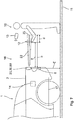
- FIG. 11 shows a plan view of an image sensor 53 of a mounting module 20 having a total number of pixels 54. Because the same image sensor 53 also monitors the detection area 21, only a few pixels 54, in particular between two and ten pixels 54, are used to image the operating area 22 on the image sensor 53. Exemplify in FIG. 11 four pixels 54, the operating area 22 from. During the monitoring of the actuation area 22, only the pixels 56 assigned to the actuation area 22 are evaluated. The remaining pixels correspond to unevaluated pixels 55.
- FIG. 12 contains a plot of a light intensity I over time ts.
- a time interval tz is shown, which is required for an image 61.
- This can be a recognition image 64 or a comparison image 63.
- the recognition image 64 has been recorded with the aid of light pulses 62 of the light module 40.
- a plurality of light pulses 62 is necessary to generate a recognition image 64.
- the light pulses 62 are emitted by the light module 40 at a predetermined pulse rate.
- the light of the light pulses 62 of an image 61 received by the image sensor 53 is integrated or summed to produce the recognition image 64.
- the optical sensor system 30 predetermines the time interval tz at which the light pulses 62 generate a recognition image 64.
- the distance of the user 10 to the optical sensor 50 is determined as a function of the intensity of the light pulses 62 in the time interval tz.
- an image 61 is recorded without light pulses 62 of the light module 40 reaching the image sensor 53.
- the light module 40 emits no light.
- the optical sensor system 30 monitors the detection area 21. If a user 10 is located in the detection area 21 and the user 10 fulfills the predetermined criteria, then the user 10 is recognized. In this case, a signal for the authentication check is triggered in a second step 72. In a third step 73, the authentication check is performed. In this case, the access control system 14 is caused by the signal triggered in step 72 to send a wake-up signal to the ID transmitter 13. Subsequently, the ID transmitter 13 transmits an authentication code to the access control system 14. The access control system 14 compares the authentication code with a stored code. If the two codes match, the authentication is successful and an unlock signal is triggered. This may be an unlocking signal for all doors of the motor vehicle 1 or else only an unlocking signal for the tailgate 2 or the side door 3.
- a signal that the user 10 has been authenticated is received by the optical sensor system 30.
- the operation area 22 is started to be monitored. For this purpose, an actuation period is started. Also, the display element 43 begins to emit visible light in a first illumination state, so that the end surface 23 of the actuation region 22 is made visible to the user 10.
- the light module 40 emits pulsed infrared light in order to be able to carry out distance measurements.
- the optical sensor 50 receives the light of the light module 40, whereby a recognition image 64 is formed. In addition, comparison images 63 are recorded and evaluated.
- the monitoring unit 60 evaluates the obtained images 61.
- the distance b can be detected and stored. If an object 18 is located in the actuation area 22, the distance a of the object 18 to the optical sensor 50 is detected in a step 76. At least one minimum distance condition is checked by the monitoring unit 60 in a step 77. So z. B. the distance a are compared with the stored in the monitoring unit minimum distance and / or the difference of the distances b and a with a maximum distance. Only when the minimum distance condition is met, in a next step 78, the display element 43 is placed in a second illumination state in which the light of the display element 43 periodically changes its brightness and thus flashes. At the same time, a distance duration t E started.
- the monitoring of the actuation area 22 is ended in a step 79 and the display element 43 is put into a third illumination state in which the display element 43 provides a warning signal to the user 10. Thereafter, after a fixed predetermined time interval in a step 80, the operating signal for opening the tailgate 2 is provided and the display element 43 is turned off.
- Is in the operating time t B is no object 18 in the operating section 22 determines and / or is in operation time t B is the minimum distance condition is not met and / or in the removal period t E is not the object 18 from the operating portion 22 is removed, so is the end of the Operation duration t B monitoring the operation range 22 is set. This is indicated by the fact that the display element 43 no longer emits light.
- steps 71 to 73 and 78 to 79 are optional.
- the working signal can be provided directly.
- Step 74 corresponds to method step a
- steps 75 to 78 correspond to method step b
- step 77 to method step d and step 80 includes method step e.
Landscapes
- Engineering & Computer Science (AREA)
- Mechanical Engineering (AREA)
- Lock And Its Accessories (AREA)
- Optical Radar Systems And Details Thereof (AREA)
- Image Processing (AREA)
Claims (16)
- Procédé (70) servant à fournir un signal de travail pour un véhicule automobile (1), avec des étapes suivantes :a) la réception d'un signal selon lequel un utilisateur (10) autorisé est authentifié,b) la surveillance d'une zone d'actionnement (22) située à l'extérieur du véhicule automobile (1) par un système de capteur (30) optique,c) la détection d'une distance (a) d'un objet (18) dans la zone d'actionnement (22) par rapport à un capteur (50) optique par le système de capteur (30) optique,d) la comparaison de la distance (a) à une spécification par le système de capteur (30) optique,e) la fourniture d'un signal de travail lorsque la spécification est remplie,caractérisé en ce que
la zone d'actionnement (22) est surveillée seulement le temps d'une durée d'actionnement (tB) spécifiée. - Procédé (70) selon la revendication 1,
caractérisé en ce que
le signal de travail est un signal servant à déverrouiller et/ou verrouiller et/ou ouvrir et/ou fermer une partie (2, 3) mobile du véhicule automobile (1), dans lequel en particulier la partie (2, 3) mobile est un hayon (2) ou une portière latérale (3) et/ou une portière coulissante. - Procédé (70) selon la revendication 1 ou 2,
caractérisé en ce que
la spécification corresponde à une condition de distance minimale de la distance (a) de l'objet (18) par rapport au capteur (50) optique. - Procédé (70) selon l'une quelconque des revendications précédentes,
caractérisé en ce que
la spécification correspond à une distance minimale, spécifiée de manière fixe et enregistrée dans le système de capteur (30) optique, de l'objet (18) par rapport au capteur (50) optique. - Procédé (70) selon l'une quelconque des revendications précédentes,
caractérisé en ce que
la spécification correspond à une valeur minimale pour un rapport entre la distance (a) de l'objet (18) par rapport au capteur (50) optique et une distance (b) d'une face d'extrémité (23) de la zone d'actionnement (22) par rapport au capteur (50) optique, dans lequel la face d'extrémité (23) se trouve en particulier au niveau d'une face de fond (15), sur laquelle se situe le véhicule automobile (1). - Procédé (70) selon l'une quelconque des revendications précédentes,
caractérisé en ce que
la spécification correspond à un éloignement (d) maximal, spécifié de manière fixe et enregistré dans le système de capteur (30) optique, d'une surface (31), tournée vers le capteur (50) optique, de l'objet (18) par rapport à la face d'extrémité (23) de la zone d'actionnement (22), qui se trouve en particulier au niveau de la face de fond (15). - Procédé (70) selon l'une quelconque des revendications précédentes,
caractérisé en ce que
le système de capteur (30) optique émet plusieurs impulsions lumineuses (62) les unes après les autres, un intervalle de temps (tz) est spécifié pour recevoir les impulsions lumineuses (62) par le système de capteur (30) optique et la distance (a) dans l'étape c) est détectée par l'intermédiaire de l'intensité des impulsions de lumière (62) reçues dans l'intervalle de temps (tz). - Procédé (70) selon l'une quelconque des revendications précédentes,
caractérisé en ce
qu'à l'étape b), des images de reconnaissance (64), qui ont été générées à l'aide de la lumière réfléchie du module lumineux (40), et des images de comparaison (63), qui ont été générées sans la lumière réfléchie du module lumineux (40) à l'aide de lumière parasite, sont prises et sont évaluées de telle sorte qu'une image de reconnaissance modifiée est générée, de laquelle la lumière parasite est éliminée. - Procédé (70) selon l'une quelconque des revendications précédentes,
caractérisé en ce que
seulement lorsqu'au moins une autre spécification est remplie, en particulier une taille de l'objet (18), une durée de séjour de l'objet (18) dans la zone d'actionnement (22), une séquence de déplacements définie de l'objet (18) dans la zone d'actionnement (22) et/ou un retrait de l'objet (18) pendant une durée de retrait (tE) spécifiée hors de la zone d'actionnement (22), le signal de travail est fourni. - Procédé (70) selon l'une quelconque des revendications précédentes,
caractérisé en ce
qu'un signal d'avertissement perceptible par l'utilisateur (10) est émis avant le déclenchement du signal de travail. - Système d'authentification (16) avec un système de contrôle d'accès (14), un transmetteur d'identification (13) et un module de montage (20) pour un véhicule automobile (1), avec un système de capteur (30) optique, qui est adaptéa) pour recevoir un signal selon lequel un utilisateur autorisé est authentifié,b) pour surveiller une zone d'actionnement (22) située à l'extérieur du véhicule automobile (1),c) pour détecter une distance (a) d'un objet (18) dans la zone d'actionnement (22) par rapport à un capteur (50) optique du système de capteur (30),d) pour comparer la distance (a) à une spécification,e) pour fournir un signal de travail lorsque la spécification est remplie, caractérisé en ceque la zone d'actionnement (22) est surveillée seulement le temps d'une durée d'actionnement (tB) spécifiée,
dans lequel le système de capteur (30) optique présente une unité de surveillance (60), qui est conçue pour évaluer des images (61), qui ont été prises par le capteur (50) optique, dans lequel
le système de capteur (30) optique présente le capteur (50) optique pour recevoir de la lumière provenant de la zone d'actionnement (21), et le système de capteur (30) optique présente un module lumineux (40) avec au moins une source de lumière (41) servant à émettre de la lumière,
dans lequel
le module de montage (20) présente un élément d'affichage (43), à travers lequel de la lumière visible peut être émise pour rendre visible à l'utilisateur (10) la durée d'actionnement (tB). - Système d'authentification (16) selon la revendication 11,
caractérisé en ce
que la source de lumière (41) est conçue pour émettre de la lumière dans la plage non visible. - Système d'authentification (16) selon l'une quelconque des revendications 11 ou 12,
caractérisé en ce
que l'élément d'affichage (43) est en outre réalisé pour rendre visible une face d'extrémité (23) de la zone d'actionnement (22) sur une face de sol (15), sur laquelle se situe le véhicule automobile (1). - Système d'authentification (16) selon l'une quelconque des revendications 11 - 13,
caractérisé en ce
que la face d'extrémité (23) de la zone d'actionnement (22) est de dimensions spatiales plus petites qu'une partie du corps, en particulier une main (12) ou un pied (11), de l'utilisateur (10). - Système d'authentification (16) selon l'une quelconque des revendications 11 - 14,
caractérisé en ce
que le capteur (50) optique présente un capteur d'image (53) avec des pixels (54), dans lequel la partie de corps (11, 12) de l'utilisateur (10) dans la zone d'actionnement (22) et/ou la zone d'actionnement (22) peut être représentée avec n pixels (54), dans lequel en particulier 2 ≤ n ≤ 10, de manière préférée n = 2, et/ou que le système de capteur (30) optique est adapté pour surveiller avant l'authentification une zone de détection (21) située à l'extérieur du véhicule automobile (1) et pour déclencher dans le cas d'une identification de l'utilisateur (10) dans la zone de détection (21) un signal pour le démarrage d'une vérification d'authentification entre un transmetteur d'identification (13) et un système de contrôle d'accès (14) du véhicule automobile (1). - Système d'authentification (16) selon l'une quelconque des revendications 11 - 15,
caractérisé en ce
que le capteur (50) optique et/ou le module lumineux (40) sont configurés pour être employés à la fois pour surveiller la zone de détection (21) et pour surveiller la zone d'actionnement (22), et/ou que le capteur (50) optique et/ou le module lumineux (40) présente un système de lentilles (42, 51) rigide.
Priority Applications (1)
| Application Number | Priority Date | Filing Date | Title |
|---|---|---|---|
| EP19190031.5A EP3666607B1 (fr) | 2014-01-31 | 2015-01-07 | Procédé de production d'un signal de travail |
Applications Claiming Priority (2)
| Application Number | Priority Date | Filing Date | Title |
|---|---|---|---|
| DE102014101192.9A DE102014101192A1 (de) | 2014-01-31 | 2014-01-31 | Verfahren zum Bereitstellen eines Arbeitssignals |
| PCT/DE2015/100010 WO2015113556A1 (fr) | 2014-01-31 | 2015-01-07 | Procédé de production d'un signal de travail |
Related Child Applications (2)
| Application Number | Title | Priority Date | Filing Date |
|---|---|---|---|
| EP19190031.5A Division EP3666607B1 (fr) | 2014-01-31 | 2015-01-07 | Procédé de production d'un signal de travail |
| EP19190031.5A Division-Into EP3666607B1 (fr) | 2014-01-31 | 2015-01-07 | Procédé de production d'un signal de travail |
Publications (2)
| Publication Number | Publication Date |
|---|---|
| EP3099540A1 EP3099540A1 (fr) | 2016-12-07 |
| EP3099540B1 true EP3099540B1 (fr) | 2019-11-20 |
Family
ID=52434474
Family Applications (2)
| Application Number | Title | Priority Date | Filing Date |
|---|---|---|---|
| EP19190031.5A Active EP3666607B1 (fr) | 2014-01-31 | 2015-01-07 | Procédé de production d'un signal de travail |
| EP15701664.3A Active EP3099540B1 (fr) | 2014-01-31 | 2015-01-07 | Procédé de production d'un signal de travail |
Family Applications Before (1)
| Application Number | Title | Priority Date | Filing Date |
|---|---|---|---|
| EP19190031.5A Active EP3666607B1 (fr) | 2014-01-31 | 2015-01-07 | Procédé de production d'un signal de travail |
Country Status (6)
| Country | Link |
|---|---|
| US (1) | US10173641B2 (fr) |
| EP (2) | EP3666607B1 (fr) |
| JP (1) | JP6670759B2 (fr) |
| CN (1) | CN105960358B (fr) |
| DE (1) | DE102014101192A1 (fr) |
| WO (1) | WO2015113556A1 (fr) |
Families Citing this family (14)
| Publication number | Priority date | Publication date | Assignee | Title |
|---|---|---|---|---|
| US10046613B2 (en) * | 2015-02-17 | 2018-08-14 | Daniel Robert Shepard | Dual purpose hitch sensor |
| DE102016211494B4 (de) * | 2016-06-27 | 2020-10-01 | Ford Global Technologies, Llc | Steuerungseinrichtung für ein Kraftfahrzeug |
| US10078927B2 (en) * | 2017-01-23 | 2018-09-18 | Honeywell International Inc. | Systems and methods for time-bound homogenous consecutive events triggering a procedure in an access control host system |
| US10442402B2 (en) * | 2017-02-27 | 2019-10-15 | Ford Global Technologies, Llc | Sensor and cleaning apparatus |
| CN114607231A (zh) * | 2017-03-31 | 2022-06-10 | 株式会社本田阿克塞斯 | 车辆用门开闭装置 |
| JP6881146B2 (ja) * | 2017-08-09 | 2021-06-02 | トヨタ自動車株式会社 | 車両用制御装置及び方法 |
| US10880293B2 (en) * | 2017-08-25 | 2020-12-29 | Ford Global Technologies, Llc | Authentication of vehicle-to-vehicle communications |
| DE102017128774B4 (de) * | 2017-12-04 | 2023-11-02 | Witte Automotive Gmbh | Optisches Sensorsystem für ein Kraftfahrzeug |
| KR102521933B1 (ko) * | 2018-10-04 | 2023-04-14 | 삼성전자주식회사 | 디스플레이장치 및 그 제어방법 |
| US20200232262A1 (en) * | 2019-01-22 | 2020-07-23 | Magna Closures Inc. | Method and system for operating a closure panel of a vehicle |
| DE102019123871A1 (de) * | 2019-09-05 | 2021-03-11 | Brose Fahrzeugteile Se & Co. Kommanditgesellschaft, Bamberg | System und Verfahren zum Verstellen einer Fahrzeugtür relativ zu einer Fahrzeugkarosserie |
| CN112180796B (zh) * | 2020-09-30 | 2023-09-19 | 辉创电子科技(苏州)有限公司 | 一种基于uwb技术的脚踢感应装置 |
| KR20230019293A (ko) * | 2021-07-29 | 2023-02-08 | 현대자동차주식회사 | 차량 및 그 제어 방법 |
| CN119037337B (zh) * | 2024-09-09 | 2025-05-13 | 湖北欧博汽车部件有限公司 | 一种车辆电动尾门解锁方法及相关设备 |
Family Cites Families (20)
| Publication number | Priority date | Publication date | Assignee | Title |
|---|---|---|---|---|
| DE102005032402B3 (de) * | 2005-07-12 | 2006-09-28 | Daimlerchrysler Ag | Verfahren zum Nachweis einer Berechtigung zum Ver- oder Entriegeln eines Objekts sowie Sicherheitsvorrichtung |
| US8091280B2 (en) | 2007-06-01 | 2012-01-10 | GM Global Technology Operations LLC | Arms full vehicle closure activation apparatus and method |
| DE102007040294B4 (de) * | 2007-08-24 | 2020-07-09 | Huf Hülsbeck & Fürst Gmbh & Co. Kg | Griffvorrichtung |
| DE102007050094A1 (de) * | 2007-10-19 | 2009-04-23 | Witte-Velbert Gmbh & Co. Kg | Schließvorrichtung für ein Kraftfahrzeugschloss mit Vorfeld-Griffmuldenbeleuchtung |
| DE102008021989A1 (de) | 2008-05-02 | 2008-12-18 | Daimler Ag | Vorrichtung zum Ver- und Entriegeln einer mittels eines elektronischen Zugangsberechtigungssystems gesicherten Fahrzeugtür für ein Fahrzeug |
| DE102008063366B4 (de) * | 2008-12-30 | 2022-04-28 | Huf Hülsbeck & Fürst Gmbh & Co. Kg | Einrichtung zum berührungslosen Betätigen einer Heckklappe eines Kraftfahrzeugs sowie Verfahren zum Betätigen einer Heckklappe eines Kraftfahrzeuges und Kraftfahrzeug |
| DE102009020218B8 (de) | 2009-05-07 | 2011-05-12 | Fraunhofer-Gesellschaft zur Förderung der angewandten Forschung e.V. | Detektor und Verfahren zum Detektieren elektromagnetischer Strahlung und Computerprogramm zur Durchführung des Verfahrens |
| DE102009023594A1 (de) * | 2009-06-02 | 2010-12-09 | Volkswagen Ag | Verfahren und Vorrichtung zur Betätigung eines Schließelements eines Fahrzeugs |
| JP2011027707A (ja) * | 2009-06-25 | 2011-02-10 | Sharp Corp | 人物動作検出装置、遊具装置、人物動作検出方法、ゲーム方法、制御プログラムおよび可読記録媒体 |
| US8305561B2 (en) * | 2010-03-25 | 2012-11-06 | Hokuyo Automatic Co., Ltd. | Scanning-type distance measuring apparatus |
| DE102010056171A1 (de) | 2010-12-24 | 2012-06-28 | Volkswagen Ag | Verfahren zum automatischen Betätigen eines Schließelements eines Fahrzeugs sowie entsprechende Vorrichtung und Fahrzeug |
| JP5895201B2 (ja) * | 2011-07-29 | 2016-03-30 | パナソニックIpマネジメント株式会社 | 車両開閉体制御装置 |
| JP2013049953A (ja) * | 2011-08-30 | 2013-03-14 | Aisin Seiki Co Ltd | 車両開閉体操作装置及びシステム |
| FR2979873B1 (fr) * | 2011-09-12 | 2013-10-04 | Valeo Securite Habitacle | Procede d'ouverture d'un ouvrant de vehicule automobile |
| DE102011115760A1 (de) * | 2011-10-12 | 2013-04-18 | Volkswagen Ag | Verfahren zur automatischen Betätigung eines Schließelements eines Fahrzeugs sowie entsprechende Vorrichtung und Fahrzeug |
| WO2013146919A1 (fr) * | 2012-03-30 | 2013-10-03 | 株式会社アルファ | Structure de commande de véhicule |
| JP2013221851A (ja) * | 2012-04-17 | 2013-10-28 | Alpha Corp | 光センサ装置 |
| KR101316873B1 (ko) * | 2012-07-04 | 2013-10-08 | 현대자동차주식회사 | 게이트 작동 시스템 및 그 방법 |
| JP6186971B2 (ja) * | 2013-07-17 | 2017-08-30 | アイシン精機株式会社 | 車両ドア開閉装置及びその制御方法 |
| US10210399B2 (en) * | 2013-12-20 | 2019-02-19 | Magna Electronics Inc. | Vehicle vision system with image processing |
-
2014
- 2014-01-31 DE DE102014101192.9A patent/DE102014101192A1/de not_active Withdrawn
-
2015
- 2015-01-07 US US15/115,646 patent/US10173641B2/en not_active Expired - Fee Related
- 2015-01-07 CN CN201580006180.7A patent/CN105960358B/zh not_active Expired - Fee Related
- 2015-01-07 EP EP19190031.5A patent/EP3666607B1/fr active Active
- 2015-01-07 EP EP15701664.3A patent/EP3099540B1/fr active Active
- 2015-01-07 JP JP2016567134A patent/JP6670759B2/ja not_active Expired - Fee Related
- 2015-01-07 WO PCT/DE2015/100010 patent/WO2015113556A1/fr not_active Ceased
Non-Patent Citations (1)
| Title |
|---|
| None * |
Also Published As
| Publication number | Publication date |
|---|---|
| CN105960358B (zh) | 2020-01-17 |
| EP3099540A1 (fr) | 2016-12-07 |
| US10173641B2 (en) | 2019-01-08 |
| US20170166168A1 (en) | 2017-06-15 |
| EP3666607B1 (fr) | 2021-11-03 |
| DE102014101192A9 (de) | 2015-11-19 |
| EP3666607A1 (fr) | 2020-06-17 |
| JP6670759B2 (ja) | 2020-03-25 |
| CN105960358A (zh) | 2016-09-21 |
| WO2015113556A1 (fr) | 2015-08-06 |
| JP2017510739A (ja) | 2017-04-13 |
| DE102014101192A1 (de) | 2015-08-06 |
Similar Documents
| Publication | Publication Date | Title |
|---|---|---|
| EP3099540B1 (fr) | Procédé de production d'un signal de travail | |
| EP3099541B1 (fr) | Module de montage | |
| EP3099547B1 (fr) | Module prêt au montage | |
| EP3099545B1 (fr) | Module prêt au montage pour véhicule à moteur | |
| EP3882089B1 (fr) | Module de montage pour véhicule à moteur | |
| EP3099544B1 (fr) | Module prêt au montage pour véhicule à moteur | |
| EP1901947B1 (fr) | Procede et dispositif de detection d'approche d'une personne ou d'un objet | |
| EP2437962B1 (fr) | Methode et dispositif pour actionner un ouvrnat d'un véhicule | |
| EP3099539B1 (fr) | Module prêt au montage pour véhicule à moteur | |
| EP3099543B1 (fr) | Module de montage destiné à un véhicule automobile, muni d'un système de détection optique et d'une commande d'urgence | |
| EP1496174A2 (fr) | Détection sans contact pour l'ouverture d'une porte véhicule et un procédé pour le déverrouillage d'une porte véhicule | |
| EP2628031A1 (fr) | Dispositif de mesure optique pour un véhicule et véhicule correspondant | |
| EP2821296A1 (fr) | Procédé de détection de gestes d'actionnement | |
| EP3466772A1 (fr) | Module de montage doté d'un élément d'affichage | |
| EP2584375B1 (fr) | Capteur de surveillance de porte et procédé de surveillance de la contre-arête de fermeture d'une porte, notamment d'une porte tournante | |
| DE10330525A1 (de) | Berührungslose Sensorik zum Öffnen eines Kraftfahrzeugs sowie Verfahren zum Entriegeln einer Kraftfahrzeugtür | |
| DE102014000426A1 (de) | Kraftfahrzeug und Verfahren zum automatischen Öffnen einer Heckklappe | |
| DE10059579A1 (de) | Verfahren zur optoelektronischen Überwachung von Funktionsbereichen und-Funktionsflächen an Maschinen, Anlagen, Bahnübergängen und Türen |
Legal Events
| Date | Code | Title | Description |
|---|---|---|---|
| PUAI | Public reference made under article 153(3) epc to a published international application that has entered the european phase |
Free format text: ORIGINAL CODE: 0009012 |
|
| STAA | Information on the status of an ep patent application or granted ep patent |
Free format text: STATUS: REQUEST FOR EXAMINATION WAS MADE |
|
| 17P | Request for examination filed |
Effective date: 20160711 |
|
| AK | Designated contracting states |
Kind code of ref document: A1 Designated state(s): AL AT BE BG CH CY CZ DE DK EE ES FI FR GB GR HR HU IE IS IT LI LT LU LV MC MK MT NL NO PL PT RO RS SE SI SK SM TR |
|
| AX | Request for extension of the european patent |
Extension state: BA ME |
|
| DAX | Request for extension of the european patent (deleted) | ||
| STAA | Information on the status of an ep patent application or granted ep patent |
Free format text: STATUS: EXAMINATION IS IN PROGRESS |
|
| 17Q | First examination report despatched |
Effective date: 20180329 |
|
| GRAP | Despatch of communication of intention to grant a patent |
Free format text: ORIGINAL CODE: EPIDOSNIGR1 |
|
| STAA | Information on the status of an ep patent application or granted ep patent |
Free format text: STATUS: GRANT OF PATENT IS INTENDED |
|
| INTG | Intention to grant announced |
Effective date: 20190401 |
|
| RIN1 | Information on inventor provided before grant (corrected) |
Inventor name: MOENIG, STEFAN Inventor name: LINDIC, IKO Inventor name: SCHINDLER, MIRKO Inventor name: ETTE, BERND Inventor name: HACHE, CHRISTOF Inventor name: ZIEGLER, ALEXANDER Inventor name: YOMKIL MALABO, JEAN Inventor name: HELLER, NORBERT Inventor name: STICHERLING, NADINE Inventor name: MUELLER, OLIVER Inventor name: SCHUMACHER, HELMUT |
|
| GRAS | Grant fee paid |
Free format text: ORIGINAL CODE: EPIDOSNIGR3 |
|
| GRAA | (expected) grant |
Free format text: ORIGINAL CODE: 0009210 |
|
| STAA | Information on the status of an ep patent application or granted ep patent |
Free format text: STATUS: THE PATENT HAS BEEN GRANTED |
|
| AK | Designated contracting states |
Kind code of ref document: B1 Designated state(s): AL AT BE BG CH CY CZ DE DK EE ES FI FR GB GR HR HU IE IS IT LI LT LU LV MC MK MT NL NO PL PT RO RS SE SI SK SM TR |
|
| REG | Reference to a national code |
Ref country code: GB Ref legal event code: FG4D Free format text: NOT ENGLISH |
|
| REG | Reference to a national code |
Ref country code: CH Ref legal event code: EP |
|
| REG | Reference to a national code |
Ref country code: IE Ref legal event code: FG4D Free format text: LANGUAGE OF EP DOCUMENT: GERMAN |
|
| REG | Reference to a national code |
Ref country code: DE Ref legal event code: R096 Ref document number: 502015010987 Country of ref document: DE |
|
| REG | Reference to a national code |
Ref country code: AT Ref legal event code: REF Ref document number: 1203837 Country of ref document: AT Kind code of ref document: T Effective date: 20191215 |
|
| REG | Reference to a national code |
Ref country code: NL Ref legal event code: MP Effective date: 20191120 |
|
| REG | Reference to a national code |
Ref country code: LT Ref legal event code: MG4D |
|
| PG25 | Lapsed in a contracting state [announced via postgrant information from national office to epo] |
Ref country code: FI Free format text: LAPSE BECAUSE OF FAILURE TO SUBMIT A TRANSLATION OF THE DESCRIPTION OR TO PAY THE FEE WITHIN THE PRESCRIBED TIME-LIMIT Effective date: 20191120 Ref country code: BG Free format text: LAPSE BECAUSE OF FAILURE TO SUBMIT A TRANSLATION OF THE DESCRIPTION OR TO PAY THE FEE WITHIN THE PRESCRIBED TIME-LIMIT Effective date: 20200220 Ref country code: SE Free format text: LAPSE BECAUSE OF FAILURE TO SUBMIT A TRANSLATION OF THE DESCRIPTION OR TO PAY THE FEE WITHIN THE PRESCRIBED TIME-LIMIT Effective date: 20191120 Ref country code: LV Free format text: LAPSE BECAUSE OF FAILURE TO SUBMIT A TRANSLATION OF THE DESCRIPTION OR TO PAY THE FEE WITHIN THE PRESCRIBED TIME-LIMIT Effective date: 20191120 Ref country code: NL Free format text: LAPSE BECAUSE OF FAILURE TO SUBMIT A TRANSLATION OF THE DESCRIPTION OR TO PAY THE FEE WITHIN THE PRESCRIBED TIME-LIMIT Effective date: 20191120 Ref country code: LT Free format text: LAPSE BECAUSE OF FAILURE TO SUBMIT A TRANSLATION OF THE DESCRIPTION OR TO PAY THE FEE WITHIN THE PRESCRIBED TIME-LIMIT Effective date: 20191120 Ref country code: NO Free format text: LAPSE BECAUSE OF FAILURE TO SUBMIT A TRANSLATION OF THE DESCRIPTION OR TO PAY THE FEE WITHIN THE PRESCRIBED TIME-LIMIT Effective date: 20200220 Ref country code: GR Free format text: LAPSE BECAUSE OF FAILURE TO SUBMIT A TRANSLATION OF THE DESCRIPTION OR TO PAY THE FEE WITHIN THE PRESCRIBED TIME-LIMIT Effective date: 20200221 |
|
| PG25 | Lapsed in a contracting state [announced via postgrant information from national office to epo] |
Ref country code: HR Free format text: LAPSE BECAUSE OF FAILURE TO SUBMIT A TRANSLATION OF THE DESCRIPTION OR TO PAY THE FEE WITHIN THE PRESCRIBED TIME-LIMIT Effective date: 20191120 Ref country code: IS Free format text: LAPSE BECAUSE OF FAILURE TO SUBMIT A TRANSLATION OF THE DESCRIPTION OR TO PAY THE FEE WITHIN THE PRESCRIBED TIME-LIMIT Effective date: 20200320 Ref country code: RS Free format text: LAPSE BECAUSE OF FAILURE TO SUBMIT A TRANSLATION OF THE DESCRIPTION OR TO PAY THE FEE WITHIN THE PRESCRIBED TIME-LIMIT Effective date: 20191120 |
|
| PG25 | Lapsed in a contracting state [announced via postgrant information from national office to epo] |
Ref country code: AL Free format text: LAPSE BECAUSE OF FAILURE TO SUBMIT A TRANSLATION OF THE DESCRIPTION OR TO PAY THE FEE WITHIN THE PRESCRIBED TIME-LIMIT Effective date: 20191120 |
|
| PG25 | Lapsed in a contracting state [announced via postgrant information from national office to epo] |
Ref country code: CZ Free format text: LAPSE BECAUSE OF FAILURE TO SUBMIT A TRANSLATION OF THE DESCRIPTION OR TO PAY THE FEE WITHIN THE PRESCRIBED TIME-LIMIT Effective date: 20191120 Ref country code: ES Free format text: LAPSE BECAUSE OF FAILURE TO SUBMIT A TRANSLATION OF THE DESCRIPTION OR TO PAY THE FEE WITHIN THE PRESCRIBED TIME-LIMIT Effective date: 20191120 Ref country code: RO Free format text: LAPSE BECAUSE OF FAILURE TO SUBMIT A TRANSLATION OF THE DESCRIPTION OR TO PAY THE FEE WITHIN THE PRESCRIBED TIME-LIMIT Effective date: 20191120 Ref country code: PT Free format text: LAPSE BECAUSE OF FAILURE TO SUBMIT A TRANSLATION OF THE DESCRIPTION OR TO PAY THE FEE WITHIN THE PRESCRIBED TIME-LIMIT Effective date: 20200412 Ref country code: EE Free format text: LAPSE BECAUSE OF FAILURE TO SUBMIT A TRANSLATION OF THE DESCRIPTION OR TO PAY THE FEE WITHIN THE PRESCRIBED TIME-LIMIT Effective date: 20191120 Ref country code: DK Free format text: LAPSE BECAUSE OF FAILURE TO SUBMIT A TRANSLATION OF THE DESCRIPTION OR TO PAY THE FEE WITHIN THE PRESCRIBED TIME-LIMIT Effective date: 20191120 |
|
| REG | Reference to a national code |
Ref country code: DE Ref legal event code: R097 Ref document number: 502015010987 Country of ref document: DE |
|
| PG25 | Lapsed in a contracting state [announced via postgrant information from national office to epo] |
Ref country code: MC Free format text: LAPSE BECAUSE OF FAILURE TO SUBMIT A TRANSLATION OF THE DESCRIPTION OR TO PAY THE FEE WITHIN THE PRESCRIBED TIME-LIMIT Effective date: 20191120 Ref country code: SM Free format text: LAPSE BECAUSE OF FAILURE TO SUBMIT A TRANSLATION OF THE DESCRIPTION OR TO PAY THE FEE WITHIN THE PRESCRIBED TIME-LIMIT Effective date: 20191120 Ref country code: SK Free format text: LAPSE BECAUSE OF FAILURE TO SUBMIT A TRANSLATION OF THE DESCRIPTION OR TO PAY THE FEE WITHIN THE PRESCRIBED TIME-LIMIT Effective date: 20191120 |
|
| REG | Reference to a national code |
Ref country code: CH Ref legal event code: PL |
|
| PLBE | No opposition filed within time limit |
Free format text: ORIGINAL CODE: 0009261 |
|
| STAA | Information on the status of an ep patent application or granted ep patent |
Free format text: STATUS: NO OPPOSITION FILED WITHIN TIME LIMIT |
|
| REG | Reference to a national code |
Ref country code: BE Ref legal event code: MM Effective date: 20200131 |
|
| 26N | No opposition filed |
Effective date: 20200821 |
|
| GBPC | Gb: european patent ceased through non-payment of renewal fee |
Effective date: 20200220 |
|
| PG25 | Lapsed in a contracting state [announced via postgrant information from national office to epo] |
Ref country code: LU Free format text: LAPSE BECAUSE OF NON-PAYMENT OF DUE FEES Effective date: 20200107 |
|
| PG25 | Lapsed in a contracting state [announced via postgrant information from national office to epo] |
Ref country code: PL Free format text: LAPSE BECAUSE OF FAILURE TO SUBMIT A TRANSLATION OF THE DESCRIPTION OR TO PAY THE FEE WITHIN THE PRESCRIBED TIME-LIMIT Effective date: 20191120 Ref country code: LI Free format text: LAPSE BECAUSE OF NON-PAYMENT OF DUE FEES Effective date: 20200131 Ref country code: BE Free format text: LAPSE BECAUSE OF NON-PAYMENT OF DUE FEES Effective date: 20200131 Ref country code: SI Free format text: LAPSE BECAUSE OF FAILURE TO SUBMIT A TRANSLATION OF THE DESCRIPTION OR TO PAY THE FEE WITHIN THE PRESCRIBED TIME-LIMIT Effective date: 20191120 Ref country code: CH Free format text: LAPSE BECAUSE OF NON-PAYMENT OF DUE FEES Effective date: 20200131 |
|
| PG25 | Lapsed in a contracting state [announced via postgrant information from national office to epo] |
Ref country code: IE Free format text: LAPSE BECAUSE OF NON-PAYMENT OF DUE FEES Effective date: 20200107 Ref country code: IT Free format text: LAPSE BECAUSE OF FAILURE TO SUBMIT A TRANSLATION OF THE DESCRIPTION OR TO PAY THE FEE WITHIN THE PRESCRIBED TIME-LIMIT Effective date: 20191120 Ref country code: GB Free format text: LAPSE BECAUSE OF NON-PAYMENT OF DUE FEES Effective date: 20200220 |
|
| REG | Reference to a national code |
Ref country code: AT Ref legal event code: MM01 Ref document number: 1203837 Country of ref document: AT Kind code of ref document: T Effective date: 20200107 |
|
| PG25 | Lapsed in a contracting state [announced via postgrant information from national office to epo] |
Ref country code: AT Free format text: LAPSE BECAUSE OF NON-PAYMENT OF DUE FEES Effective date: 20200107 |
|
| PG25 | Lapsed in a contracting state [announced via postgrant information from national office to epo] |
Ref country code: TR Free format text: LAPSE BECAUSE OF FAILURE TO SUBMIT A TRANSLATION OF THE DESCRIPTION OR TO PAY THE FEE WITHIN THE PRESCRIBED TIME-LIMIT Effective date: 20191120 Ref country code: MT Free format text: LAPSE BECAUSE OF FAILURE TO SUBMIT A TRANSLATION OF THE DESCRIPTION OR TO PAY THE FEE WITHIN THE PRESCRIBED TIME-LIMIT Effective date: 20191120 Ref country code: CY Free format text: LAPSE BECAUSE OF FAILURE TO SUBMIT A TRANSLATION OF THE DESCRIPTION OR TO PAY THE FEE WITHIN THE PRESCRIBED TIME-LIMIT Effective date: 20191120 |
|
| PGFP | Annual fee paid to national office [announced via postgrant information from national office to epo] |
Ref country code: FR Payment date: 20220120 Year of fee payment: 8 |
|
| PG25 | Lapsed in a contracting state [announced via postgrant information from national office to epo] |
Ref country code: MK Free format text: LAPSE BECAUSE OF FAILURE TO SUBMIT A TRANSLATION OF THE DESCRIPTION OR TO PAY THE FEE WITHIN THE PRESCRIBED TIME-LIMIT Effective date: 20191120 |
|
| P01 | Opt-out of the competence of the unified patent court (upc) registered |
Effective date: 20230426 |
|
| PG25 | Lapsed in a contracting state [announced via postgrant information from national office to epo] |
Ref country code: FR Free format text: LAPSE BECAUSE OF NON-PAYMENT OF DUE FEES Effective date: 20230131 |
|
| PGFP | Annual fee paid to national office [announced via postgrant information from national office to epo] |
Ref country code: DE Payment date: 20250120 Year of fee payment: 11 |