EP3666607A1 - Procédé de production d'un signal de travail - Google Patents
Procédé de production d'un signal de travail Download PDFInfo
- Publication number
- EP3666607A1 EP3666607A1 EP19190031.5A EP19190031A EP3666607A1 EP 3666607 A1 EP3666607 A1 EP 3666607A1 EP 19190031 A EP19190031 A EP 19190031A EP 3666607 A1 EP3666607 A1 EP 3666607A1
- Authority
- EP
- European Patent Office
- Prior art keywords
- optical sensor
- distance
- light
- area
- actuation area
- Prior art date
- Legal status (The legal status is an assumption and is not a legal conclusion. Google has not performed a legal analysis and makes no representation as to the accuracy of the status listed.)
- Granted
Links
Images




Classifications
-
- B—PERFORMING OPERATIONS; TRANSPORTING
- B60—VEHICLES IN GENERAL
- B60R—VEHICLES, VEHICLE FITTINGS, OR VEHICLE PARTS, NOT OTHERWISE PROVIDED FOR
- B60R25/00—Fittings or systems for preventing or indicating unauthorised use or theft of vehicles
- B60R25/20—Means to switch the anti-theft system on or off
- B60R25/24—Means to switch the anti-theft system on or off using electronic identifiers containing a code not memorised by the user
-
- B—PERFORMING OPERATIONS; TRANSPORTING
- B60—VEHICLES IN GENERAL
- B60R—VEHICLES, VEHICLE FITTINGS, OR VEHICLE PARTS, NOT OTHERWISE PROVIDED FOR
- B60R11/00—Arrangements for holding or mounting articles, not otherwise provided for
- B60R11/04—Mounting of cameras operative during drive; Arrangement of controls thereof relative to the vehicle
-
- E—FIXED CONSTRUCTIONS
- E05—LOCKS; KEYS; WINDOW OR DOOR FITTINGS; SAFES
- E05B—LOCKS; ACCESSORIES THEREFOR; HANDCUFFS
- E05B81/00—Power-actuated vehicle locks
- E05B81/54—Electrical circuits
- E05B81/64—Monitoring or sensing, e.g. by using switches or sensors
- E05B81/76—Detection of handle operation; Detection of a user approaching a handle; Electrical switching actions performed by door handles
- E05B81/77—Detection of handle operation; Detection of a user approaching a handle; Electrical switching actions performed by door handles comprising sensors detecting the presence of the hand of a user
-
- E—FIXED CONSTRUCTIONS
- E05—LOCKS; KEYS; WINDOW OR DOOR FITTINGS; SAFES
- E05B—LOCKS; ACCESSORIES THEREFOR; HANDCUFFS
- E05B81/00—Power-actuated vehicle locks
- E05B81/54—Electrical circuits
- E05B81/64—Monitoring or sensing, e.g. by using switches or sensors
- E05B81/76—Detection of handle operation; Detection of a user approaching a handle; Electrical switching actions performed by door handles
- E05B81/78—Detection of handle operation; Detection of a user approaching a handle; Electrical switching actions performed by door handles as part of a hands-free locking or unlocking operation
-
- B—PERFORMING OPERATIONS; TRANSPORTING
- B60—VEHICLES IN GENERAL
- B60R—VEHICLES, VEHICLE FITTINGS, OR VEHICLE PARTS, NOT OTHERWISE PROVIDED FOR
- B60R11/00—Arrangements for holding or mounting articles, not otherwise provided for
- B60R2011/0001—Arrangements for holding or mounting articles, not otherwise provided for characterised by position
- B60R2011/004—Arrangements for holding or mounting articles, not otherwise provided for characterised by position outside the vehicle
-
- B—PERFORMING OPERATIONS; TRANSPORTING
- B60—VEHICLES IN GENERAL
- B60R—VEHICLES, VEHICLE FITTINGS, OR VEHICLE PARTS, NOT OTHERWISE PROVIDED FOR
- B60R25/00—Fittings or systems for preventing or indicating unauthorised use or theft of vehicles
- B60R25/10—Fittings or systems for preventing or indicating unauthorised use or theft of vehicles actuating a signalling device
-
- G—PHYSICS
- G01—MEASURING; TESTING
- G01C—MEASURING DISTANCES, LEVELS OR BEARINGS; SURVEYING; NAVIGATION; GYROSCOPIC INSTRUMENTS; PHOTOGRAMMETRY OR VIDEOGRAMMETRY
- G01C21/00—Navigation; Navigational instruments not provided for in groups G01C1/00 - G01C19/00
- G01C21/26—Navigation; Navigational instruments not provided for in groups G01C1/00 - G01C19/00 specially adapted for navigation in a road network
- G01C21/34—Route searching; Route guidance
- G01C21/3407—Route searching; Route guidance specially adapted for specific applications
-
- G—PHYSICS
- G06—COMPUTING OR CALCULATING; COUNTING
- G06T—IMAGE DATA PROCESSING OR GENERATION, IN GENERAL
- G06T2207/00—Indexing scheme for image analysis or image enhancement
- G06T2207/30—Subject of image; Context of image processing
- G06T2207/30196—Human being; Person
-
- G—PHYSICS
- G06—COMPUTING OR CALCULATING; COUNTING
- G06V—IMAGE OR VIDEO RECOGNITION OR UNDERSTANDING
- G06V20/00—Scenes; Scene-specific elements
- G06V20/50—Context or environment of the image
- G06V20/56—Context or environment of the image exterior to a vehicle by using sensors mounted on the vehicle
-
- G—PHYSICS
- G06—COMPUTING OR CALCULATING; COUNTING
- G06V—IMAGE OR VIDEO RECOGNITION OR UNDERSTANDING
- G06V40/00—Recognition of biometric, human-related or animal-related patterns in image or video data
- G06V40/10—Human or animal bodies, e.g. vehicle occupants or pedestrians; Body parts, e.g. hands
- G06V40/103—Static body considered as a whole, e.g. static pedestrian or occupant recognition
-
- G—PHYSICS
- G07—CHECKING-DEVICES
- G07C—TIME OR ATTENDANCE REGISTERS; REGISTERING OR INDICATING THE WORKING OF MACHINES; GENERATING RANDOM NUMBERS; VOTING OR LOTTERY APPARATUS; ARRANGEMENTS, SYSTEMS OR APPARATUS FOR CHECKING NOT PROVIDED FOR ELSEWHERE
- G07C2209/00—Indexing scheme relating to groups G07C9/00 - G07C9/38
- G07C2209/60—Indexing scheme relating to groups G07C9/00174 - G07C9/00944
- G07C2209/63—Comprising locating means for detecting the position of the data carrier, i.e. within the vehicle or within a certain distance from the vehicle
- G07C2209/64—Comprising locating means for detecting the position of the data carrier, i.e. within the vehicle or within a certain distance from the vehicle using a proximity sensor
Definitions
- the invention relates to a method for providing a working signal for a motor vehicle according to claim 1. Furthermore, the invention relates to an assembly module for a motor vehicle according to independent claim 12.
- the DE 10 2008 021 989 A1 discloses a method for providing a work signal for a motor vehicle, in which a visible control panel is provided. If the user touches the control panel z. B. with one foot, an automatic opening of the vehicle door can be initiated after unlocking a vehicle door.
- the disadvantage of this is that the user initiates the opening of the vehicle door even when the user is completely in the control panel.
- the user can be hit and injured by the vehicle door.
- the opening of the vehicle door can be initiated if, for. B. a cat or dog runs through the control panel and the user is directly at the vehicle door, so that the user can be hit and injured by the vehicle door in this case.
- step b) is carried out after step a).
- Steps c) and d) are carried out in particular during step b). If the specification is met, step b) in particular is ended and step e) is carried out.
- the comparison can be a direct comparison in which the distance recorded in step c) is compared directly with the specification, or an indirect comparison in which a further size is determined by the distance and this is then compared with the specification.
- step d) the distance detected in step c) is related to a specification.
- a working signal is not provided for distances that do not meet the specification. Rather, the working signal is only provided if the specification is met.
- the condition ensures that an action by the user in the actuation area, which should not trigger the work signal, or an undesired object, such as. B. a dog, does not trigger the work signal in the operating area. Rather, the work signal is only triggered by a conscious action by the user.
- the conscious action of the user can be carried out in particular with one hand or one foot.
- the working signal is not provided undesirably or unexpectedly does not surprise the user. Rather, a user's will is recognized. Thus, the process triggered by the work signal, e.g. B. opening a moving part of the motor vehicle, the user less.
- the work signal can be a signal for unlocking and / or locking and / or opening and / or closing a movable part of the motor vehicle.
- the movable part can in particular be a tailgate and / or a side door of the motor vehicle.
- the tailgate and / or the side door can be designed as a sliding door. Due to the working signal, the moving part z. B. be unlocked. Due to the spring action of a seal, the movable part can then move partially from a closed position and thus partially open.
- the working signal can be a signal for activating a motorized opening and / or closing aid.
- the motor vehicle has a motor that opens and / or closes the movable part completely.
- the work signal can be a signal for retracting and / or extending a trailer coupling.
- several different user wills such as. B. the will of the user to open a moving part, and the will of the user to extend the towbar, are determined.
- the actuation area ends on a floor surface on which the motor vehicle stands.
- the actuation area has an end surface on the bottom surface.
- the actuation area can run essentially orthogonal to the floor surface or have an inclination angle to a plane that runs parallel to a plane connecting the vehicle axles. This angle of inclination corresponds in particular to the angle of inclination of the optical sensor.
- the actuation area has a frustoconical area with a round or elliptical base area.
- the frustoconical area can correspond in particular to an oblique truncated cone.
- the specification preferably corresponds to a minimum distance condition for the distance of the object from the optical sensor.
- the working signal is therefore only provided if the object does not come too close to the optical sensor. This ensures that the user is far enough from the optical sensor. Since the optical sensor can be installed in the vicinity of the movable part, this can result in the user being far enough away from the movable part. The safety of the user can thus be further increased.
- the minimum distance condition can be stored as a fixed value in the optical sensor system. Alternatively, the minimum distance condition can be kept variable. So the minimum distance condition z. B. from a floor surface on which the motor vehicle stands to be dependent. The minimum distance condition can be stored in a monitoring unit of the optical sensor system.
- the specification in particular the minimum distance condition, can correspond to a fixed, predetermined minimum distance of the object from the optical sensor that is stored in the optical sensor system.
- the working signal is only provided if the distance between the object and the optical sensor exceeds the minimum distance.
- An absolute value for the minimum distance of the object from the optical sensor can be stored in the optical sensor system, in particular in the monitoring unit.
- the distance between the object and the optical sensor is recorded while the actuation area is being monitored. The requirement is only met if the distance recorded is greater than the minimum distance.
- the minimum distance can vary with an installation height with which the optical sensor is to be installed in the motor vehicle.
- the minimum distance from the angle of inclination of the optical sensor can also vary.
- the minimum distance can be chosen larger, the greater the installation height and / or the lower the angle of inclination.
- the choice of a fixed minimum distance from the optical sensor has the advantage that a direct limit value for the variable recorded in step c) is selected as the default and thus the computing capacity of the optical sensor system is protected. Likewise, no other sizes need to be entered as a default when choosing the fixed minimum distance.
- the specification in particular the minimum distance condition, corresponds to a minimum value for a ratio of the distance of the object to the optical sensor to a distance of an end face of the actuation area from the optical sensor.
- the work signal is only provided if the minimum value for the ratio is exceeded by a corresponding distance from the object to the optical sensor.
- An absolute value for the minimum value for the ratio can be permanently stored in the optical sensor system, in particular in the monitoring unit.
- the distance between the end face of the actuation area and the optical sensor can be stored as a fixed value in the optical sensor system or can preferably be detected by the optical sensor system during monitoring. The distance between the object and the optical sensor is recorded while the actuation area is being monitored.
- the ratio of the distance of the object to the optical sensor to the distance of the end face of the actuation area to the optical sensor is formed. Only if the ratio is bigger than the minimum value, the default is met.
- the minimum value can vary with the installation height and the angle of inclination of the optical sensor. In particular, the minimum value can be increased with increasing installation height and decreasing angle of inclination.
- the minimum value is selected as the default, then a changing operating range can advantageously be taken into account in the default.
- the specification can correspond to the minimum value for a ratio of the distance of the object to the optical sensor to a distance of the floor area in the actuation area to the optical sensor. If the floor area is hilly, the hilly floor area can be taken into account in fulfilling the specification.
- the specification, in particular the minimum distance condition corresponds to a fixed, predetermined and stored in the optical sensor system maximum distance of a surface of the object facing the optical sensor to an end surface of the actuation area, which is located in particular on a floor surface .
- the working signal is only provided if the distance of the surface of the object facing the optical sensor to an end surface of the actuation area, in particular on the floor surface, falls below the maximum distance.
- An absolute value for the maximum distance can be stored in the optical sensor system, in particular in the monitoring unit.
- the distance between the end face of the actuation area and the optical sensor can be stored as a fixed value in the optical sensor system or can preferably be detected by the optical sensor system during monitoring.
- the distance between the object and the optical sensor is recorded while the actuation area is being monitored.
- the distance between a surface of the object facing the optical sensor and the end surface of the actuation region, in particular the floor surface, is determined from the distance between the end surface of the actuation area and the optical sensor and the distance of the object from the optical sensor.
- the specification is only met if the distance determined in this way is less than the maximum distance. This creates a further possibility to take into account a varying length of the actuation area, in particular with a varying floor area.
- a contact angle on the bottom surface and the distances of the object and the end surface from the optical sensor can be used to determine a distance c, orthogonal to the bottom surface, of the surface of the object facing the optical sensor from the end surface. It is conceivable that the working signal is only provided if the distance c falls below a maximum distance. The maximum distance can be fixed in the optical sensor system.
- the angle of impact corresponds to the angle of inclination on a flat floor surface. It is conceivable to use the angle of inclination instead of the angle of incidence for simplification.
- the minimum distance condition can be designed such that the distance c may correspond to a maximum distance in order to meet the specification.
- the user must step on the floor surface in the actuation area in order to meet the specification.
- the maximum distance c max for the distance c can be chosen to be 0 c c max 30 30 cm, preferably 0 c c max 20 20 cm, particularly preferably 0 c c max 10 10 cm. Even if another minimum distance condition is selected, it can be specified so that the conditions mentioned apply for c max .
- a fixed minimum distance, a minimum value for the ratio, a fixed maximum distance and / or a fixed maximum distance can be provided.
- the detected distances can in particular be distances averaged over the entire object and / or over the entire end surface.
- individual points of the object and / or the end surface can be involved.
- the distance of the object to the optical sensor and the distance of the end face to the optical sensor, which lie on a straight line, are related to each other.
- the optical sensor system can determine, in particular on the basis of a change in intensity of the received light, that an object is located in the actuation area.
- a time of flight measurement can be carried out, for example.
- for. B. emits one or more light pulses from the optical sensor system, in particular from a light module of the optical sensor system, and measures the time that the light pulse takes to the object and from there to the optical sensor.
- the time is directly proportional to the distance of the object. It may be that a plurality of light pulses are emitted one after the other by the optical sensor system, in particular by the light module, in order to be able to generate an image.
- the light pulses can be integrated or summed up to produce the image.
- a specific time interval for the image recording is specified in the optical sensor system. The total intensity of the light pulses received in the optical sensor in the time interval is correlated with the distance.
- recognition images and comparison images are recorded and, if necessary, evaluated.
- Recognition images are created with the help of the reflection of the light module's emitted light.
- Comparison pictures are only created with the help of stray light.
- the stray light can be, for example, sunlight or light from an artificial light source, e.g. B. garage light, act.
- the light module does not emit any light to produce the comparison images.
- the monitoring unit can recognize the stray light by comparing a detection image and a comparison image.
- the optical sensor system in particular the monitoring unit, can generate a modified detection image from which the stray light is removed. It can be provided that a comparison image is recorded after a predetermined number of identification images.
- the actuation area is only monitored for a predetermined actuation duration t B.
- a maximum length of the actuation period t B can be predetermined and stored in the optical sensor system. Distances between objects that are outside the actuation period t B in the actuation area are not recorded. This means that no working signal can be triggered outside the actuation period t B.
- the operating time can only trigger a work signal in a limited period of time, so that the risk of false tripping is reduced.
- the actuation time t B can in particular be chosen to be short. For example, t B with 3 s t t B 30 30 s, preferably 5 s t t B 15 15 s, can be selected.
- the actuation period t B can be started in particular by receiving the signal that an authorized user is authenticated and / or starting immediately after receiving this signal.
- the duration of the operation can be after the maximum length or prematurely, e.g. B. end with the provision of the work signal or with the fulfillment of the required specification (s). It can be provided that the beginning and the end of the actuation period t B can be perceived by the user.
- the working signal can preferably only be provided if at least one further specification is met. This also increases security for the user.
- the size of the object can be determined during the monitoring.
- the working signal can only be provided if the size exceeds a minimum size and / or falls below a maximum size.
- a defined movement sequence of the object can be specified in the actuation area.
- the work signal is only provided if the defined movement sequence takes place.
- it can e.g. B. act on a given gesture.
- It may be that several measurements of the distance of the object from the optical sensor are carried out in order to be able to recognize the movement sequence in the actuation area.
- the distance is recorded for at least two successive images, in particular recognition images. The distance can be measured by a time of flight measurement.
- the duration of the object's stay in the actuation area is recorded during the monitoring. Only if the length of stay is one The working signal can be provided if the minimum length of stay exceeds and / or falls below a maximum length of stay.
- the object must be removed from the actuation area within a predetermined distance duration t E so that the working signal is provided.
- the distance duration t E begins.
- the start of the distance duration t E is perceptible to the user.
- the work signal is only provided if the object, in particular a body part of the user, is removed from the actuation area within the removal time t E.
- a second actuation area is present.
- the second actuation area can also be monitored by the optical sensor system. It is thus conceivable that an object must be in the second actuation area, in particular in the second actuation area one of the specifications already mentioned must be met in order for the work signal to be provided. Additionally or alternatively, a minimum distance and / or a certain position of the authorized user from the optical sensor and / or from the motor vehicle may be necessary so that the working signal is provided. Regarding the position z. B. determine whether the user is in front of, next to or behind the motor vehicle. The minimum distance and / or position can be determined at any time during or after authentication.
- the minimum distance and / or the position can also be determined after the end of the actuation period.
- the distance of the authorized user from the motor vehicle and / or from the optical sensor and / or the position of the authorized user is recorded.
- the distance of the user from the motor vehicle and / or a position of the user, for. B. can be determined based on the strength of a signal emitted by an ID transmitter.
- the Receive Signal Strength Indicator (RSSI) can be used for this. By determining the strength of the transmitted signal, it can be ensured that only the authorized user himself has entered the detection area and has expressed his will to use the area of operation. It is conceivable to poll the RSSI cyclically.
- the distance of the user from the optical sensor can be determined by the optical sensor system.
- a detection area that is farther away than the actuation area from Motor vehicle ends are monitored by the optical sensor system and the distance of the user to the optical sensor is detected in the detection area.
- the work signal is only triggered if the user is at a minimum distance from the motor vehicle and / or from the optical sensor and / or is in a predetermined position on the motor vehicle.
- warning signal Another way of increasing the safety of the user can be achieved by a warning signal.
- a warning signal that can be perceived by the user can be issued before the work signal is triggered.
- a detection area outside the motor vehicle can first be monitored by the optical sensor system and, if the user is recognized in the detection area, a signal for the start of an authentication check between an ID transmitter and an access control system of the motor vehicle can be triggered. An authentication check can then take place through the authentication system. Process steps a) to e) can follow these steps.
- the detection area is monitored in particular in order to be able to determine the proximity of a user.
- a passive keyless entry check can be initiated, in particular, by monitoring the detection area and triggering a start signal for the authentication check.
- the user does not have to operate the ID transmitter to trigger the authentication check.
- the additional method steps have the advantage that with the same optical sensor system or authentication system both the authentication check can be initiated or carried out, which also carry out method steps a) to e).
- the recognition of a user in the detection area can be based on the fulfillment of certain criteria such as size, length of stay, movement and / or direction of movement of the user.
- an authentication system with an assembly module according to the invention, an ID transmitter and an access control system.
- the assembly module and / or the authentication system is suitable for carrying out a method according to the invention.
- the optical sensor system can have a monitoring unit with a processor and a memory, with the aid of which the method according to the invention can be carried out.
- the method according to the invention can be stored in the memory.
- the optical monitoring unit can also be designed to evaluate images that have been recorded by the optical sensor.
- the optical sensor system can have the optical sensor in order to receive light from the actuation area.
- the optical sensor takes pictures of the operating area.
- the optical sensor can have a lens system and / or an image sensor.
- the image sensor can be a CMOS sensor and / or an LDPD sensor.
- the LDPD sensor (Lateral Drift Field Photodetector) is in the publication DE 10 2009 020 218 B3 described. The LDPD sensor is suitable for being evaluated particularly quickly.
- the optical sensor system can have a light module for emitting light.
- the light serves to create the operating area.
- the light module have a lens system. It can be provided that the light module emits light in the non-visible area.
- the light can be infrared rays, in particular near infrared rays.
- the light module can have only one light source.
- the light module can have multiple light sources.
- the light sources can be arranged around the optical sensor. So z. B. light sources to the left and right of the optical sensor. Alternatively, the light sources can be arranged around the circumference of the optical sensor.
- the light can be laser light.
- the light emitted by the light module can be pulsed.
- the optical sensor has an infrared filter and / or a polarization filter. In this way, at least part of an interfering light can be filtered out.
- the light module can also have a polarization filter.
- the mounting module can have a fastening element, in particular an installation plate, in order to mount individual elements of the optical sensor system, i. H. to fix the optical sensor, the light module and / or the monitoring unit.
- the mounting module can comprise a housing which at least partially surrounds the optical sensor system.
- the monitoring unit can be designed together with the access control system.
- the fastening element can be designed like a spherical segment.
- the optical sensor system or the entire assembly module for arrangement on the rear of the vehicle, for. B. behind the rear window, in a handle bar, in an emblem, in a rear light, behind a cat's eye, on a bumper and / or in a gap between two components.
- the mounting module can be suitable, for. B. to be attached in a B-pillar.
- the optical sensor system or the entire assembly module can be hidden behind a layer which is opaque from the outside, but which is translucent to the light of the optical sensor system. So z. B. the bumper on which the optical sensor system is mounted, be painted.
- the optical sensor system is preferably arranged on the motor vehicle in such a way that it is not very dirty.
- the optical sensor system can be arranged behind the rear window in the wiping area of the window wiper or on the handle bar.
- the assembly module can have a washing nozzle with which the optical Sensor system can be cleaned. The washing nozzle can z. B. always automatically clean the optical sensor system when the wiper of the front and / or rear window is actuated.
- the mounting module can have a display element through which visible light can be emitted. As a result, at least part of the actuation area can be made visible to the user. In particular, an end surface of the actuation area lying on the bottom surface can be made visible.
- the display element can make the actuation duration visible to the user. It is conceivable that the display element is switched on at the beginning of the actuation period. Here, the display element can assume a first lighting state. If the actuation period ends, the display element can be switched off. Alternatively, the display element can change to a second lighting state after the actuation period, which serves as a warning signal. It is also conceivable that the display element can assume a third lighting state that signals the duration of the distance. In one of the lighting states, in particular in the first lighting state, the display element can emit light of a constant brightness. In the other lighting condition or in the other lighting conditions, z. B. the brightness change periodically. Different lighting states can have periods of different lengths.
- the intensity of the visible light emitted by the display element can depend on the brightness of the ambient light.
- the brightness of the ambient light can be determined by a brightness sensor.
- the display element is preferably arranged close to the optical sensor and / or to the light module.
- the area visible by the display element on the floor area can correspond sufficiently with the end face of the actuation area.
- the distance f of the display element to the optical sensor and / or light module is 1 cm f f 10 10 cm, preferably 1 cm f f 3 3 cm.
- an end surface of the actuation area is of smaller spatial dimensions than a body part, in particular a hand or a foot, of the user. This ensures that in the action provided for the user only a surface that is as flat as possible, e.g. B. a front sheet of a shoe or a palm comes into the operating area. It is therefore easier to determine a distance from the object to the optical sensor.
- the image sensor has pixels.
- the actuation area is preferably displayed on the image sensor with only a small number of pixels. This can reduce production and operating costs.
- the body part of the user can preferably be represented at any point in the actuation area with at least the number of pixels mentioned.
- the body part of the user is represented with a pixel number greater than 1 in order not to endanger the method according to the invention by a defective pixel.
- the optical sensor system can be suitable for monitoring a detection area outside the motor vehicle prior to authentication and, if the user is recognized in the detection area, triggering a signal for the start of an authentication check between an ID transmitter and an access control system of the motor vehicle.
- the optical sensor and / or the light module can be designed to be used both for monitoring the detection area and for monitoring the actuation area.
- the same optical sensor and / or the same light module are used to monitor the detection and the actuation area.
- the optical sensor and / or the light module can have a rigid lens system.
- the light module for monitoring the detection area can emit the same light with respect to the wavelength and / or the duration of a light pulse as for monitoring the actuation area.
- the detection area and / or the actuation area can first be monitored with light of a longer wavelength than the subsequent checking of the distance and / or other requirements that are imposed the recognition of a user and / or user will be made. So first z. B. light of a wavelength of 905 nm can be used. Then z. B. Light of a wavelength of 800 nm can be used.
- the assembly module can be designed such that the detection area ends farther away from the motor vehicle than the actuation area in a plan view. This ensures that after a positive authentication the actuation area is between the user and the motor vehicle. That is, the user can usually maintain his direction of movement to reach the operating area.
- the actuation area can be located within the detection area. Alternatively, it can be provided that the actuation area is closer to the motor vehicle than the detection area in a plan view. In particular, the actuation area can adjoin the detection area.
- the assembly module and / or motor vehicle has at least one means which makes it easier for the user to make the user's wishes known in the actuation area, so that the work signal is triggered.
- the assembly module can thus send out an advisory signal that the actuation period will end shortly.
- the warning signal can e.g. B. begin by changing the lighting state of the display element.
- the warning signal can correspond to a different lighting state of the display element. For example, the display element may flash at the end of the actuation period.
- the agent corresponds to a corresponding method specification in the monitoring unit.
- the assembly module and / or the motor vehicle can have means by which a perceptible, in particular visible, audible or tactile, signal can be generated for the user.
- the mounting module lighting elements for. B. LEDs.
- the lighting elements can be arranged such that the lighting elements act as signposts Act.
- the lighting elements can be aligned in such a way that they produce markings on the floor surface that lead to the actuation area. Additionally or alternatively, the lighting elements can be arranged side by side.
- the lighting elements can be switched on in a sequence that shows the user in which direction the user has to move towards the operating area.
- existing lighting elements arranged next to one another in the motor vehicle e.g. B. the light elements of a headlight, a brake light, turn signals or the like can be used.
- the assembly module can have a loudspeaker.
- notify the change of direction to the ID transmitter who uses various vibrations to show the user the way. If the user is informed of a change in direction, the optical sensor system determines the position of the user and the direction in which he has to move to the actuation area and causes the perceptible means to send out the corresponding signal.
- the position of the actuation area and / or the length of the actuation duration can be changed. This is particularly helpful when a physically impaired user wants to express his or her user will. This is also helpful if the actuation area is arranged in a position which is unfavorable for the user.
- the unfavorable position can be permanent.
- the operating range can end on a trailer hitch.
- the unfavorable position can only be unfavorable for triggering a one-time work signal, e.g. B. because the operating area ends at a puddle.
- a predefined user action can be provided.
- the predefined user action can be recognized by the optical sensor system.
- the assembly module can be transferred to a learning mode in which the assembly module learns the changed position of the actuation area and / or the changed length of the actuation area.
- the actuation area is monitored again in order to determine a user's will to trigger a work signal after a first actuation period has ended without recognizing a user will. This is particularly helpful if the user was distracted and did not reach the operating area in time or carried out the wrong gestures. It can therefore be provided that the actuation area can be monitored several times, in particular two or three times, in succession. The monitoring of the actuation area can be initiated automatically. Alternatively, a predefined user action can be provided in order to monitor the actuation area again for a further actuation period. For this purpose, for example, a capacitive sensor can be addressed by the user. Alternatively, it can be a predefined user action that is recognized by the optical sensor system.
- the predefined user action which is recognized by the optical sensor system and which causes a change in the position of the actuation area and / or the actuation period and / or a renewed monitoring of the actuation area to recognize a user will, can be, for example, the following user actions: a predetermined gesture within the actuation and / or detection area, for example a back and forth movement of a body part of the user, non-removal of the body part, if removal was provided, movement of the user into the detection and / or actuation area and / or out of the Detection and / or actuation area.
- the body part can be a hand or a foot.
- the display element also shows this. If the position of the actuation area is changed, the display element shows this.
- the display element can have several illuminants, e.g. B. LEDs. One or more illuminants each make an actuation area at least partially visible.
- the actuation area with the changed position is preferably within the detection area. Depending on which actuation area is monitored, the corresponding pixels are evaluated.
- the invention also includes an authentication system with an ID transmitter, an access control system and an assembly module according to the invention.
- the assembly module can be configured as described and / or claimed.
- the authentication system is suitable for carrying out the authentication check for an access authorization. After the assembly module has triggered the signal for the authentication check, the authentication check can be continued.
- the access control system can send a wake-up signal to the ID transmitter.
- the ID transmitter can then send an authentication code to the access control system.
- the access control system can compare the received authentication code with a stored code. In particular, in the event of a match, i.e. H. in case of successful authentication, a signal will be triggered. This can be an unlocking signal. Alternatively, it is a signal to start monitoring the actuation area.
- the unlocking signal is only triggered when at least one further signal, in particular the working signal, and / or a further authentication has taken place.
- the work signal also includes the unlock signal.
- the authentication system can also be suitable for determining a minimum distance of the user from the motor vehicle.
- FIG. 1 An assembly module 20 according to the invention and an authentication system 16 according to the invention have been used in a motor vehicle 1 according to the invention. Use in a rear area of motor vehicle 1 with a tailgate 2 is shown here.
- An optical sensor system 30 of the assembly module 20 is in the region of the tailgate 2, e.g. B. arranged in a handle of the tailgate 2.
- An actuation area 22 lying outside the motor vehicle 1 is generated by the optical sensor system 30.
- the optical sensor system 30 monitors the actuation area 22. To start the monitoring, the optical sensor system 30 receives a signal from Access control system 14 that an authorized user is authenticated. For this purpose, the access control system 14 had previously sent a wake-up signal to an ID transmitter 13 and the ID transmitter 13 had sent an authentication code to the access control system 14.
- the actuation area 22 extends, having an oblique truncated cone, from a proximity to the optical sensor system 30 to a floor surface 15 on which the motor vehicle 1 is standing.
- the actuation area 22 ends at the bottom surface 15 with an end surface 23.
- the actuation area 22 has an inclination angle ⁇ to a plane 24 which is parallel to the bottom surface 15 and / or to a plane 17 which runs parallel to a plane connecting the vehicle axles.
- an object 18, in this case a foot 11 of a user 10 is in the actuation area 22, the distance a of the object 18 to an optical sensor 50 of the optical sensor system 30 is detected.
- a light module 40 of the optical sensor system 30 emits pulsed, infrared light.
- the light of the light module is reflected on the object 18 and received by the optical sensor 50.
- the optical sensor 50 is evaluated by a monitoring unit 60 of the optical sensor system 30. To determine the distance a, a time-of-flight measurement can be carried out.
- the optical sensor 50, the light module 40 and the monitoring unit 60 are shown in FIG Figure 10 shown.
- the monitoring unit 60 compares the detected distance a with a specification.
- the monitoring unit 60 only provides a work signal for opening the tailgate 2 if the specification is met. This creates a condition for the provision of the work signal so that not every object 18 in the actuation area 22 triggers the work signal. Rather, there must be a user will to hold the object 18 in the actuation area 22 in such a way that the specification is met and the work signal is provided. The security for the user 10 is thus increased. It is provided here that the user 10 moves his foot 11 into the actuation area 22 in order to indicate his will to use the user. When the tailgate 2 is opened, the tailgate 2 moves out of a door lock 8.
- the distance a can be compared directly with a minimum distance stored in the monitoring unit 60.
- the specification is only met if the distance a exceeds the minimum distance.
- the distance b between the end face 23 and the optical sensor 50 can first be detected as long as there is still no object 18 in the actuation area 22.
- a ratio of the distance a to the distance b is formed and the value of this ratio is compared with a minimum value stored in the monitoring unit. The specification is only met if the ratio of the distance a to the distance b exceeds the minimum value.
- the difference d between the distances a and b can be formed.
- the difference d denotes a distance from the surface 31 of the object 18 facing the optical sensor 50 to the end surface 23.
- the specification is only met if the difference d falls below a maximum distance.
- the distance c which describes the distance between the surface facing the optical sensor and the end face 23, can be formed. The specification is only met if the distance c falls below a maximum value.
- a minimum distance condition is formulated by the above-mentioned specifications, by means of which the object must not come too close to the optical sensor. Thus, a user who comes too close to the motor vehicle 1 or a dog 19 in the actuation area 22 does not trigger the work signal.
- the other options of specifying also take into account an undulating floor surface 15.
- Figure 2 it is shown how the floor area 15 rises behind the motor vehicle 1.
- Figure 3 the floor area 15 lowers behind the motor vehicle 1. This can often be found in garage driveways.
- Figure 2 can at the same height of the foot 11 above the floor surface 15, the first possibility of The specification is no longer met, while the second to fourth options for the specification are met.
- the foot 11 on the other hand, can fulfill all the possibilities of the specification.
- the second to fourth possibility of the specification prevents a dog 19 from fulfilling the specification.
- the minimum distance requirement can, however, be formulated in such a way that the user can use a puddle as in Figure 4 shown, hold the foot over the end surface 23 and still meet the minimum distance requirement. So z. B. a value of 30 cm can be selected for the maximum distance of the distance c. Corresponding other minimum distance conditions are conceivable according to the installation height E and / or the angle of inclination ⁇ .
- FIG. 5 the size of the end surface 23 is shown in comparison to the foot 11.
- the end surface 23 has smaller spatial dimensions than the foot 11, so that a meaningful average distance a of the foot 11 to the optical sensor 50 can be easily detected.
- FIG 6 A display element 43 of the assembly module 20 is shown. This display element 43 is also in the assembly module 20 Figures 1 to 4 available, but for the sake of clarity in the Figures 1 to 4 not shown.
- the display element 43 serves to make the end face 23 of the actuation area 22 visible to the user 10. For this purpose, the display element 43 emits visible light 46.
- the display element 43 is arranged close to the optical sensor system 30. This makes it possible for the area of the floor surface 15 illuminated by the display element 43 to be sufficiently congruent with the end area 23 even when the floor surface 15 is uneven.
- FIG. 7 A second assembly module 20 according to the invention is shown.
- the actuation area 22 ends completely above the floor area 15. It is provided that the authorized user 10 reaches with his hand 12 into the actuation area 22 such that the hand 12 fulfills the minimum distance condition and the work signal is provided.
- the first to third possibilities for a minimum distance condition are conceivable here.
- the end surface of the actuation area 22 is due to the decreasing intensity of the light emitted by the light module 40.
- the display element 43 does not make the end face 23 of the actuation area 22 visible, but instead, by emitting visible light, indicates an actuation duration t B during which an object in the actuation area 22 which fulfills the minimum distance condition can trigger the work signal.
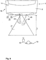
- Figure 8 shows a third exemplary embodiment of an assembly module 20 according to the invention and an authentication system 16 according to the invention.
- the optical sensor system 30 of the assembly module 20 of the Figure 8 is able to monitor a detection area 21.
- the detection area 21 is monitored from parking the motor vehicle 1 until successful authentication.
- a user 10 can be recognized in the detection area 21 by the optical sensor system 30. If the user 10 is recognized, a signal to start an authentication check is triggered.
- the authentication check is carried out independently by the access control system 14 and the ID transmitter 13. Here, the user 10 does not have to operate the ID transmitter 13, so that it is a passive entry check.
- the optical sensor system 30 receives a signal that the user has been successfully authenticated.
- the optical sensor system 30 then monitors the actuation area 22.
- the detection area has the length L.
- the actuation area 22 is of smaller spatial dimensions than the detection area 21 and lies within the detection area 21.
- the actuation area 22 ends closer to the motor vehicle 1 than the detection area 21.
- the actuation area 22 may be the only actuation area.
- a second actuation area 28 is additionally shown.
- an object 18 must meet the minimum spacing condition in both actuation areas 22, 28 within a predefined actuation period t B in order to to provide the working signal.
- a second display element 45 of the assembly module 20 serves to make the second actuation area 28 visible.
- FIG. 9 shows a fourth exemplary embodiment of how the assembly module 20 according to the invention and the authentication system 16 according to the invention are used.
- the mounting module 20 is in the Figure 9 arranged in a B-pillar 4 of a vehicle side.
- An approach to a side door 3 of the motor vehicle 1 is monitored by the detection area 21.
- the working signal can serve to open the side door 3.
- the actuation area 22 ends closer to the motor vehicle 1 than the detection area 21.
- the actuation area 22 lies outside the detection area 21.
- the actuation area 22 of the exemplary embodiment of FIG Figure 9 encompasses the area of the door handle 5.
- a hand 12 of the user 10 which is in the vicinity of the door handle 5, in particular fulfills the minimum distance requirement.
- the third exemplary embodiment of an assembly module 20 according to the invention is shown in a plan view.
- the mounting module 20 has an installation plate 25 as a fastening element, an optical sensor system 30 and a display element 43.
- the optical sensor system 30 has a light module 40, which in Figure 10 is designed as a single light source 41.
- the light source 41 emits infrared light, whereby a transmission area 27 is created.
- the shape and shape of the transmission area 27 are achieved by a lens system 42 of the light source 41, which is only shown schematically.
- the optical sensor system 30 also has an optical sensor 50 which can receive light from a reception area 26.
- the shape and shape of the reception area 26 are predetermined by a schematically illustrated lens system 51 of the optical sensor 50.
- the detection area 21 shown with a thick line thickness results from the superimposition of the transmission area 27 with the detection area 26.
- the optical sensor 50 has an infrared filter 52 in order to filter light of other wavelengths. Furthermore, the optical sensor has an image sensor 53 on which the image is formed.
- a monitoring unit 60 serves to evaluate the optical sensor 50.
- the optical sensor 50, the light module 40 and the monitoring unit 60 are fastened on the installation plate 25.
- the lens systems 42, 51 are rigid.
- the actuation area 22 lies within the detection area 21. This corresponds to the third exemplary embodiment.
- the detection area 21 and the actuation area 22 can be formed separately in the area of the overlay of the transmission and reception area, so that the detection and actuation area 21, 22 as in FIG Figure 9 are arranged.
- the display element 43 is at a short distance f from the optical sensor 50.
- Figure 11 shows a top view of an image sensor 53 of an assembly module 20 according to the invention, which has a total number of pixels 54. Because the detection area 21 is also monitored with the same image sensor 53, only a few pixels 54, in particular between two and ten pixels 54, are used in order to image the actuation area 22 on the image sensor 53. Exemplary form in Figure 11 four pixels 54 from the actuation area 22. During the monitoring of the actuation area 22, only the pixels 56 assigned to the actuation area 22 are evaluated. The remaining pixels correspond to pixels 55 not evaluated.
- Figure 12 contains a plot of light intensity I over time ts.
- an image 61 is recorded with the aid of the image sensor 53 after each time t, wherein in the Figure 12 A time interval t Z is shown that is required for an image 61.
- This can be a recognition image 64 or a comparison image 63.
- the detection image 64 was recorded with the aid of light pulses 62 from the light module 40.
- a large number of light pulses 62 are required in order to generate a recognition image 64.
- the light pulses 62 are emitted by the light module 40 at a predetermined pulse frequency.
- the light of the light pulses 62 of an image 61 received by the image sensor 53 is integrated or added up in order to generate the recognition image 64.
- the optical sensor system 30 specifies the time interval tz in which the light pulses 62 generate a recognition image 64.
- the distance between the user 10 and the optical sensor 50 is determined as a function of the intensity of the light pulses 62 in the time interval tz.
- An image 61 is recorded in the comparison image 63 without light pulses 62 of the light module 40 reaching the image sensor 53.
- the light module 40 does not emit any light.
- a method according to the invention is shown.
- the optical sensor system 30 monitors the detection area 21. If there is a user 10 in the detection area 21 and the user 10 fulfills the specified criteria, the user 10 is recognized. In this case, a signal for the authentication check is triggered in a second step 72.
- the authentication check is carried out.
- the access control system 14 is prompted by the signal triggered in step 72 to send a wake-up signal to the ID transmitter 13.
- the ID transmitter 13 then transmits an authentication code to the access control system 14.
- the access control system 14 compares the authentication code with a stored code. If the two codes match, the authentication is successful and an unlock signal is triggered. This can be an unlocking signal for all doors of motor vehicle 1 or just an unlocking signal for tailgate 2 or side door 3.
- a signal that the user 10 has been authenticated is received by the optical sensor system 30 in a fourth step 74.
- the actuation area 22 is started to be monitored. For this purpose, an actuation period is started.
- the display element 43 likewise begins to emit visible light in a first lighting state, so that the end face 23 of the actuation area 22 is made visible to the user 10.
- the light module 40 emits pulsed infrared light in order to be able to carry out distance measurements.
- the optical sensor 50 receives the light from the light module 40, whereby a recognition image 64 is created.
- comparison images 63 are recorded and evaluated.
- the monitoring unit 60 evaluates the images 61 obtained.
- the distance b can first be recorded and stored.
- the distance a of the object 18 to the optical sensor 50 is detected in a step 76.
- At least one minimum distance condition is checked in a step 77 by the monitoring unit 60. So z. B. the distance a can be compared with the minimum distance stored in the monitoring unit and / or the difference between the distances b and a with a maximum distance.
- Only in a next step 78 is the display element 43 placed in a second lighting state in which the light of the display element 43 changes its brightness periodically and thus flashes only if the minimum distance condition is fulfilled.
- a distance duration t E started.
- the monitoring of the actuation area 22 is ended in a step 79 and the display element 43 is set to a third lighting state in which the display element 43 provides a warning signal to the user 10.
- the work signal for opening the tailgate 2 is provided in a step 80 and the display element 43 is switched off.
- the Actuation time t B the monitoring of the actuation area 22 is set. This is indicated by the fact that the display element 43 no longer emits light.
- steps 71 to 73 and 78 to 79 are optional.
- the working signal can be provided directly directly after step 77.
- Step 74 corresponds to step a
- steps 75 to 78 correspond to step b
- step 76 corresponds to step c
- step 77 corresponds to step d
- step 80 contains step e.
Landscapes
- Engineering & Computer Science (AREA)
- Mechanical Engineering (AREA)
- Lock And Its Accessories (AREA)
- Optical Radar Systems And Details Thereof (AREA)
- Image Processing (AREA)
Applications Claiming Priority (3)
| Application Number | Priority Date | Filing Date | Title |
|---|---|---|---|
| DE102014101192.9A DE102014101192A1 (de) | 2014-01-31 | 2014-01-31 | Verfahren zum Bereitstellen eines Arbeitssignals |
| EP15701664.3A EP3099540B1 (fr) | 2014-01-31 | 2015-01-07 | Procédé de production d'un signal de travail |
| PCT/DE2015/100010 WO2015113556A1 (fr) | 2014-01-31 | 2015-01-07 | Procédé de production d'un signal de travail |
Related Parent Applications (2)
| Application Number | Title | Priority Date | Filing Date |
|---|---|---|---|
| EP15701664.3A Division EP3099540B1 (fr) | 2014-01-31 | 2015-01-07 | Procédé de production d'un signal de travail |
| EP15701664.3A Division-Into EP3099540B1 (fr) | 2014-01-31 | 2015-01-07 | Procédé de production d'un signal de travail |
Publications (2)
| Publication Number | Publication Date |
|---|---|
| EP3666607A1 true EP3666607A1 (fr) | 2020-06-17 |
| EP3666607B1 EP3666607B1 (fr) | 2021-11-03 |
Family
ID=52434474
Family Applications (2)
| Application Number | Title | Priority Date | Filing Date |
|---|---|---|---|
| EP19190031.5A Active EP3666607B1 (fr) | 2014-01-31 | 2015-01-07 | Procédé de production d'un signal de travail |
| EP15701664.3A Active EP3099540B1 (fr) | 2014-01-31 | 2015-01-07 | Procédé de production d'un signal de travail |
Family Applications After (1)
| Application Number | Title | Priority Date | Filing Date |
|---|---|---|---|
| EP15701664.3A Active EP3099540B1 (fr) | 2014-01-31 | 2015-01-07 | Procédé de production d'un signal de travail |
Country Status (6)
| Country | Link |
|---|---|
| US (1) | US10173641B2 (fr) |
| EP (2) | EP3666607B1 (fr) |
| JP (1) | JP6670759B2 (fr) |
| CN (1) | CN105960358B (fr) |
| DE (1) | DE102014101192A1 (fr) |
| WO (1) | WO2015113556A1 (fr) |
Families Citing this family (14)
| Publication number | Priority date | Publication date | Assignee | Title |
|---|---|---|---|---|
| US10046613B2 (en) * | 2015-02-17 | 2018-08-14 | Daniel Robert Shepard | Dual purpose hitch sensor |
| DE102016211494B4 (de) * | 2016-06-27 | 2020-10-01 | Ford Global Technologies, Llc | Steuerungseinrichtung für ein Kraftfahrzeug |
| US10078927B2 (en) * | 2017-01-23 | 2018-09-18 | Honeywell International Inc. | Systems and methods for time-bound homogenous consecutive events triggering a procedure in an access control host system |
| US10442402B2 (en) * | 2017-02-27 | 2019-10-15 | Ford Global Technologies, Llc | Sensor and cleaning apparatus |
| CN114607231A (zh) * | 2017-03-31 | 2022-06-10 | 株式会社本田阿克塞斯 | 车辆用门开闭装置 |
| JP6881146B2 (ja) * | 2017-08-09 | 2021-06-02 | トヨタ自動車株式会社 | 車両用制御装置及び方法 |
| US10880293B2 (en) * | 2017-08-25 | 2020-12-29 | Ford Global Technologies, Llc | Authentication of vehicle-to-vehicle communications |
| DE102017128774B4 (de) * | 2017-12-04 | 2023-11-02 | Witte Automotive Gmbh | Optisches Sensorsystem für ein Kraftfahrzeug |
| KR102521933B1 (ko) * | 2018-10-04 | 2023-04-14 | 삼성전자주식회사 | 디스플레이장치 및 그 제어방법 |
| US20200232262A1 (en) * | 2019-01-22 | 2020-07-23 | Magna Closures Inc. | Method and system for operating a closure panel of a vehicle |
| DE102019123871A1 (de) * | 2019-09-05 | 2021-03-11 | Brose Fahrzeugteile Se & Co. Kommanditgesellschaft, Bamberg | System und Verfahren zum Verstellen einer Fahrzeugtür relativ zu einer Fahrzeugkarosserie |
| CN112180796B (zh) * | 2020-09-30 | 2023-09-19 | 辉创电子科技(苏州)有限公司 | 一种基于uwb技术的脚踢感应装置 |
| KR20230019293A (ko) * | 2021-07-29 | 2023-02-08 | 현대자동차주식회사 | 차량 및 그 제어 방법 |
| CN119037337B (zh) * | 2024-09-09 | 2025-05-13 | 湖北欧博汽车部件有限公司 | 一种车辆电动尾门解锁方法及相关设备 |
Citations (9)
| Publication number | Priority date | Publication date | Assignee | Title |
|---|---|---|---|---|
| DE102005032402B3 (de) * | 2005-07-12 | 2006-09-28 | Daimlerchrysler Ag | Verfahren zum Nachweis einer Berechtigung zum Ver- oder Entriegeln eines Objekts sowie Sicherheitsvorrichtung |
| DE102008021989A1 (de) | 2008-05-02 | 2008-12-18 | Daimler Ag | Vorrichtung zum Ver- und Entriegeln einer mittels eines elektronischen Zugangsberechtigungssystems gesicherten Fahrzeugtür für ein Fahrzeug |
| DE102007050094A1 (de) * | 2007-10-19 | 2009-04-23 | Witte-Velbert Gmbh & Co. Kg | Schließvorrichtung für ein Kraftfahrzeugschloss mit Vorfeld-Griffmuldenbeleuchtung |
| DE102009023594A1 (de) * | 2009-06-02 | 2010-12-09 | Volkswagen Ag | Verfahren und Vorrichtung zur Betätigung eines Schließelements eines Fahrzeugs |
| DE102009020218B3 (de) | 2009-05-07 | 2011-01-13 | Fraunhofer-Gesellschaft zur Förderung der angewandten Forschung e.V. | Detektor und Verfahren zum Detektieren elektromagnetischer Strahlung und Computerprogramm zur Durchführung des Verfahrens |
| DE102010056171A1 (de) * | 2010-12-24 | 2012-06-28 | Volkswagen Ag | Verfahren zum automatischen Betätigen eines Schließelements eines Fahrzeugs sowie entsprechende Vorrichtung und Fahrzeug |
| JP2013049953A (ja) * | 2011-08-30 | 2013-03-14 | Aisin Seiki Co Ltd | 車両開閉体操作装置及びシステム |
| WO2013037806A1 (fr) * | 2011-09-12 | 2013-03-21 | Valeo Securite Habitacle | Procédé d'ouverture d'un ouvrant de véhicule automobile |
| DE102011115760A1 (de) * | 2011-10-12 | 2013-04-18 | Volkswagen Ag | Verfahren zur automatischen Betätigung eines Schließelements eines Fahrzeugs sowie entsprechende Vorrichtung und Fahrzeug |
Family Cites Families (11)
| Publication number | Priority date | Publication date | Assignee | Title |
|---|---|---|---|---|
| US8091280B2 (en) | 2007-06-01 | 2012-01-10 | GM Global Technology Operations LLC | Arms full vehicle closure activation apparatus and method |
| DE102007040294B4 (de) * | 2007-08-24 | 2020-07-09 | Huf Hülsbeck & Fürst Gmbh & Co. Kg | Griffvorrichtung |
| DE102008063366B4 (de) * | 2008-12-30 | 2022-04-28 | Huf Hülsbeck & Fürst Gmbh & Co. Kg | Einrichtung zum berührungslosen Betätigen einer Heckklappe eines Kraftfahrzeugs sowie Verfahren zum Betätigen einer Heckklappe eines Kraftfahrzeuges und Kraftfahrzeug |
| JP2011027707A (ja) * | 2009-06-25 | 2011-02-10 | Sharp Corp | 人物動作検出装置、遊具装置、人物動作検出方法、ゲーム方法、制御プログラムおよび可読記録媒体 |
| US8305561B2 (en) * | 2010-03-25 | 2012-11-06 | Hokuyo Automatic Co., Ltd. | Scanning-type distance measuring apparatus |
| JP5895201B2 (ja) * | 2011-07-29 | 2016-03-30 | パナソニックIpマネジメント株式会社 | 車両開閉体制御装置 |
| WO2013146919A1 (fr) * | 2012-03-30 | 2013-10-03 | 株式会社アルファ | Structure de commande de véhicule |
| JP2013221851A (ja) * | 2012-04-17 | 2013-10-28 | Alpha Corp | 光センサ装置 |
| KR101316873B1 (ko) * | 2012-07-04 | 2013-10-08 | 현대자동차주식회사 | 게이트 작동 시스템 및 그 방법 |
| JP6186971B2 (ja) * | 2013-07-17 | 2017-08-30 | アイシン精機株式会社 | 車両ドア開閉装置及びその制御方法 |
| US10210399B2 (en) * | 2013-12-20 | 2019-02-19 | Magna Electronics Inc. | Vehicle vision system with image processing |
-
2014
- 2014-01-31 DE DE102014101192.9A patent/DE102014101192A1/de not_active Withdrawn
-
2015
- 2015-01-07 US US15/115,646 patent/US10173641B2/en not_active Expired - Fee Related
- 2015-01-07 CN CN201580006180.7A patent/CN105960358B/zh not_active Expired - Fee Related
- 2015-01-07 EP EP19190031.5A patent/EP3666607B1/fr active Active
- 2015-01-07 EP EP15701664.3A patent/EP3099540B1/fr active Active
- 2015-01-07 JP JP2016567134A patent/JP6670759B2/ja not_active Expired - Fee Related
- 2015-01-07 WO PCT/DE2015/100010 patent/WO2015113556A1/fr not_active Ceased
Patent Citations (9)
| Publication number | Priority date | Publication date | Assignee | Title |
|---|---|---|---|---|
| DE102005032402B3 (de) * | 2005-07-12 | 2006-09-28 | Daimlerchrysler Ag | Verfahren zum Nachweis einer Berechtigung zum Ver- oder Entriegeln eines Objekts sowie Sicherheitsvorrichtung |
| DE102007050094A1 (de) * | 2007-10-19 | 2009-04-23 | Witte-Velbert Gmbh & Co. Kg | Schließvorrichtung für ein Kraftfahrzeugschloss mit Vorfeld-Griffmuldenbeleuchtung |
| DE102008021989A1 (de) | 2008-05-02 | 2008-12-18 | Daimler Ag | Vorrichtung zum Ver- und Entriegeln einer mittels eines elektronischen Zugangsberechtigungssystems gesicherten Fahrzeugtür für ein Fahrzeug |
| DE102009020218B3 (de) | 2009-05-07 | 2011-01-13 | Fraunhofer-Gesellschaft zur Förderung der angewandten Forschung e.V. | Detektor und Verfahren zum Detektieren elektromagnetischer Strahlung und Computerprogramm zur Durchführung des Verfahrens |
| DE102009023594A1 (de) * | 2009-06-02 | 2010-12-09 | Volkswagen Ag | Verfahren und Vorrichtung zur Betätigung eines Schließelements eines Fahrzeugs |
| DE102010056171A1 (de) * | 2010-12-24 | 2012-06-28 | Volkswagen Ag | Verfahren zum automatischen Betätigen eines Schließelements eines Fahrzeugs sowie entsprechende Vorrichtung und Fahrzeug |
| JP2013049953A (ja) * | 2011-08-30 | 2013-03-14 | Aisin Seiki Co Ltd | 車両開閉体操作装置及びシステム |
| WO2013037806A1 (fr) * | 2011-09-12 | 2013-03-21 | Valeo Securite Habitacle | Procédé d'ouverture d'un ouvrant de véhicule automobile |
| DE102011115760A1 (de) * | 2011-10-12 | 2013-04-18 | Volkswagen Ag | Verfahren zur automatischen Betätigung eines Schließelements eines Fahrzeugs sowie entsprechende Vorrichtung und Fahrzeug |
Also Published As
| Publication number | Publication date |
|---|---|
| CN105960358B (zh) | 2020-01-17 |
| EP3099540A1 (fr) | 2016-12-07 |
| US10173641B2 (en) | 2019-01-08 |
| US20170166168A1 (en) | 2017-06-15 |
| EP3666607B1 (fr) | 2021-11-03 |
| DE102014101192A9 (de) | 2015-11-19 |
| JP6670759B2 (ja) | 2020-03-25 |
| CN105960358A (zh) | 2016-09-21 |
| WO2015113556A1 (fr) | 2015-08-06 |
| JP2017510739A (ja) | 2017-04-13 |
| DE102014101192A1 (de) | 2015-08-06 |
| EP3099540B1 (fr) | 2019-11-20 |
Similar Documents
| Publication | Publication Date | Title |
|---|---|---|
| EP3666607B1 (fr) | Procédé de production d'un signal de travail | |
| EP3099545B1 (fr) | Module prêt au montage pour véhicule à moteur | |
| EP3882089B1 (fr) | Module de montage pour véhicule à moteur | |
| EP3099542B1 (fr) | Logo pour véhicule à moteur comportant un système capteur, et procédé correspondant | |
| EP3099539B1 (fr) | Module prêt au montage pour véhicule à moteur | |
| EP3099543B1 (fr) | Module de montage destiné à un véhicule automobile, muni d'un système de détection optique et d'une commande d'urgence | |
| EP3099544B1 (fr) | Module prêt au montage pour véhicule à moteur | |
| EP3099547B1 (fr) | Module prêt au montage | |
| EP3099541B1 (fr) | Module de montage | |
| EP1496174A2 (fr) | Détection sans contact pour l'ouverture d'une porte véhicule et un procédé pour le déverrouillage d'une porte véhicule | |
| EP3466772A1 (fr) | Module de montage doté d'un élément d'affichage |
Legal Events
| Date | Code | Title | Description |
|---|---|---|---|
| PUAI | Public reference made under article 153(3) epc to a published international application that has entered the european phase |
Free format text: ORIGINAL CODE: 0009012 |
|
| STAA | Information on the status of an ep patent application or granted ep patent |
Free format text: STATUS: THE APPLICATION HAS BEEN PUBLISHED |
|
| AC | Divisional application: reference to earlier application |
Ref document number: 3099540 Country of ref document: EP Kind code of ref document: P |
|
| AK | Designated contracting states |
Kind code of ref document: A1 Designated state(s): AL AT BE BG CH CY CZ DE DK EE ES FI FR GB GR HR HU IE IS IT LI LT LU LV MC MK MT NL NO PL PT RO RS SE SI SK SM TR |
|
| STAA | Information on the status of an ep patent application or granted ep patent |
Free format text: STATUS: REQUEST FOR EXAMINATION WAS MADE |
|
| 17P | Request for examination filed |
Effective date: 20201217 |
|
| RBV | Designated contracting states (corrected) |
Designated state(s): AL AT BE BG CH CY CZ DE DK EE ES FI FR GB GR HR HU IE IS IT LI LT LU LV MC MK MT NL NO PL PT RO RS SE SI SK SM TR |
|
| GRAP | Despatch of communication of intention to grant a patent |
Free format text: ORIGINAL CODE: EPIDOSNIGR1 |
|
| STAA | Information on the status of an ep patent application or granted ep patent |
Free format text: STATUS: GRANT OF PATENT IS INTENDED |
|
| INTG | Intention to grant announced |
Effective date: 20210607 |
|
| GRAS | Grant fee paid |
Free format text: ORIGINAL CODE: EPIDOSNIGR3 |
|
| GRAA | (expected) grant |
Free format text: ORIGINAL CODE: 0009210 |
|
| STAA | Information on the status of an ep patent application or granted ep patent |
Free format text: STATUS: THE PATENT HAS BEEN GRANTED |
|
| AC | Divisional application: reference to earlier application |
Ref document number: 3099540 Country of ref document: EP Kind code of ref document: P |
|
| AK | Designated contracting states |
Kind code of ref document: B1 Designated state(s): AL AT BE BG CH CY CZ DE DK EE ES FI FR GB GR HR HU IE IS IT LI LT LU LV MC MK MT NL NO PL PT RO RS SE SI SK SM TR |
|
| REG | Reference to a national code |
Ref country code: GB Ref legal event code: FG4D Free format text: NOT ENGLISH |
|
| REG | Reference to a national code |
Ref country code: AT Ref legal event code: REF Ref document number: 1443695 Country of ref document: AT Kind code of ref document: T Effective date: 20211115 Ref country code: CH Ref legal event code: EP |
|
| REG | Reference to a national code |
Ref country code: IE Ref legal event code: FG4D Free format text: LANGUAGE OF EP DOCUMENT: GERMAN |
|
| REG | Reference to a national code |
Ref country code: DE Ref legal event code: R096 Ref document number: 502015015374 Country of ref document: DE |
|
| REG | Reference to a national code |
Ref country code: LT Ref legal event code: MG9D |
|
| REG | Reference to a national code |
Ref country code: NL Ref legal event code: MP Effective date: 20211103 |
|
| PG25 | Lapsed in a contracting state [announced via postgrant information from national office to epo] |
Ref country code: RS Free format text: LAPSE BECAUSE OF FAILURE TO SUBMIT A TRANSLATION OF THE DESCRIPTION OR TO PAY THE FEE WITHIN THE PRESCRIBED TIME-LIMIT Effective date: 20211103 Ref country code: LT Free format text: LAPSE BECAUSE OF FAILURE TO SUBMIT A TRANSLATION OF THE DESCRIPTION OR TO PAY THE FEE WITHIN THE PRESCRIBED TIME-LIMIT Effective date: 20211103 Ref country code: FI Free format text: LAPSE BECAUSE OF FAILURE TO SUBMIT A TRANSLATION OF THE DESCRIPTION OR TO PAY THE FEE WITHIN THE PRESCRIBED TIME-LIMIT Effective date: 20211103 Ref country code: BG Free format text: LAPSE BECAUSE OF FAILURE TO SUBMIT A TRANSLATION OF THE DESCRIPTION OR TO PAY THE FEE WITHIN THE PRESCRIBED TIME-LIMIT Effective date: 20220203 |
|
| PGFP | Annual fee paid to national office [announced via postgrant information from national office to epo] |
Ref country code: GB Payment date: 20220125 Year of fee payment: 8 |
|
| PG25 | Lapsed in a contracting state [announced via postgrant information from national office to epo] |
Ref country code: IS Free format text: LAPSE BECAUSE OF FAILURE TO SUBMIT A TRANSLATION OF THE DESCRIPTION OR TO PAY THE FEE WITHIN THE PRESCRIBED TIME-LIMIT Effective date: 20220303 Ref country code: SE Free format text: LAPSE BECAUSE OF FAILURE TO SUBMIT A TRANSLATION OF THE DESCRIPTION OR TO PAY THE FEE WITHIN THE PRESCRIBED TIME-LIMIT Effective date: 20211103 Ref country code: PT Free format text: LAPSE BECAUSE OF FAILURE TO SUBMIT A TRANSLATION OF THE DESCRIPTION OR TO PAY THE FEE WITHIN THE PRESCRIBED TIME-LIMIT Effective date: 20220303 Ref country code: PL Free format text: LAPSE BECAUSE OF FAILURE TO SUBMIT A TRANSLATION OF THE DESCRIPTION OR TO PAY THE FEE WITHIN THE PRESCRIBED TIME-LIMIT Effective date: 20211103 Ref country code: NO Free format text: LAPSE BECAUSE OF FAILURE TO SUBMIT A TRANSLATION OF THE DESCRIPTION OR TO PAY THE FEE WITHIN THE PRESCRIBED TIME-LIMIT Effective date: 20220203 Ref country code: NL Free format text: LAPSE BECAUSE OF FAILURE TO SUBMIT A TRANSLATION OF THE DESCRIPTION OR TO PAY THE FEE WITHIN THE PRESCRIBED TIME-LIMIT Effective date: 20211103 Ref country code: LV Free format text: LAPSE BECAUSE OF FAILURE TO SUBMIT A TRANSLATION OF THE DESCRIPTION OR TO PAY THE FEE WITHIN THE PRESCRIBED TIME-LIMIT Effective date: 20211103 Ref country code: HR Free format text: LAPSE BECAUSE OF FAILURE TO SUBMIT A TRANSLATION OF THE DESCRIPTION OR TO PAY THE FEE WITHIN THE PRESCRIBED TIME-LIMIT Effective date: 20211103 Ref country code: GR Free format text: LAPSE BECAUSE OF FAILURE TO SUBMIT A TRANSLATION OF THE DESCRIPTION OR TO PAY THE FEE WITHIN THE PRESCRIBED TIME-LIMIT Effective date: 20220204 Ref country code: ES Free format text: LAPSE BECAUSE OF FAILURE TO SUBMIT A TRANSLATION OF THE DESCRIPTION OR TO PAY THE FEE WITHIN THE PRESCRIBED TIME-LIMIT Effective date: 20211103 |
|
| PGFP | Annual fee paid to national office [announced via postgrant information from national office to epo] |
Ref country code: FR Payment date: 20220120 Year of fee payment: 8 |
|
| PG25 | Lapsed in a contracting state [announced via postgrant information from national office to epo] |
Ref country code: SM Free format text: LAPSE BECAUSE OF FAILURE TO SUBMIT A TRANSLATION OF THE DESCRIPTION OR TO PAY THE FEE WITHIN THE PRESCRIBED TIME-LIMIT Effective date: 20211103 Ref country code: SK Free format text: LAPSE BECAUSE OF FAILURE TO SUBMIT A TRANSLATION OF THE DESCRIPTION OR TO PAY THE FEE WITHIN THE PRESCRIBED TIME-LIMIT Effective date: 20211103 Ref country code: RO Free format text: LAPSE BECAUSE OF FAILURE TO SUBMIT A TRANSLATION OF THE DESCRIPTION OR TO PAY THE FEE WITHIN THE PRESCRIBED TIME-LIMIT Effective date: 20211103 Ref country code: EE Free format text: LAPSE BECAUSE OF FAILURE TO SUBMIT A TRANSLATION OF THE DESCRIPTION OR TO PAY THE FEE WITHIN THE PRESCRIBED TIME-LIMIT Effective date: 20211103 Ref country code: DK Free format text: LAPSE BECAUSE OF FAILURE TO SUBMIT A TRANSLATION OF THE DESCRIPTION OR TO PAY THE FEE WITHIN THE PRESCRIBED TIME-LIMIT Effective date: 20211103 Ref country code: CZ Free format text: LAPSE BECAUSE OF FAILURE TO SUBMIT A TRANSLATION OF THE DESCRIPTION OR TO PAY THE FEE WITHIN THE PRESCRIBED TIME-LIMIT Effective date: 20211103 |
|
| REG | Reference to a national code |
Ref country code: DE Ref legal event code: R097 Ref document number: 502015015374 Country of ref document: DE |
|
| PG25 | Lapsed in a contracting state [announced via postgrant information from national office to epo] |
Ref country code: MC Free format text: LAPSE BECAUSE OF FAILURE TO SUBMIT A TRANSLATION OF THE DESCRIPTION OR TO PAY THE FEE WITHIN THE PRESCRIBED TIME-LIMIT Effective date: 20211103 |
|
| REG | Reference to a national code |
Ref country code: CH Ref legal event code: PL |
|
| PLBE | No opposition filed within time limit |
Free format text: ORIGINAL CODE: 0009261 |
|
| STAA | Information on the status of an ep patent application or granted ep patent |
Free format text: STATUS: NO OPPOSITION FILED WITHIN TIME LIMIT |
|
| REG | Reference to a national code |
Ref country code: BE Ref legal event code: MM Effective date: 20220131 |
|
| 26N | No opposition filed |
Effective date: 20220804 |
|
| PG25 | Lapsed in a contracting state [announced via postgrant information from national office to epo] |
Ref country code: LU Free format text: LAPSE BECAUSE OF NON-PAYMENT OF DUE FEES Effective date: 20220107 Ref country code: AL Free format text: LAPSE BECAUSE OF FAILURE TO SUBMIT A TRANSLATION OF THE DESCRIPTION OR TO PAY THE FEE WITHIN THE PRESCRIBED TIME-LIMIT Effective date: 20211103 |
|
| PG25 | Lapsed in a contracting state [announced via postgrant information from national office to epo] |
Ref country code: SI Free format text: LAPSE BECAUSE OF FAILURE TO SUBMIT A TRANSLATION OF THE DESCRIPTION OR TO PAY THE FEE WITHIN THE PRESCRIBED TIME-LIMIT Effective date: 20211103 Ref country code: BE Free format text: LAPSE BECAUSE OF NON-PAYMENT OF DUE FEES Effective date: 20220131 |
|
| PG25 | Lapsed in a contracting state [announced via postgrant information from national office to epo] |
Ref country code: LI Free format text: LAPSE BECAUSE OF NON-PAYMENT OF DUE FEES Effective date: 20220131 Ref country code: CH Free format text: LAPSE BECAUSE OF NON-PAYMENT OF DUE FEES Effective date: 20220131 |
|
| PG25 | Lapsed in a contracting state [announced via postgrant information from national office to epo] |
Ref country code: IE Free format text: LAPSE BECAUSE OF NON-PAYMENT OF DUE FEES Effective date: 20220107 |
|
| REG | Reference to a national code |
Ref country code: AT Ref legal event code: MM01 Ref document number: 1443695 Country of ref document: AT Kind code of ref document: T Effective date: 20220107 |
|
| PG25 | Lapsed in a contracting state [announced via postgrant information from national office to epo] |
Ref country code: AT Free format text: LAPSE BECAUSE OF NON-PAYMENT OF DUE FEES Effective date: 20220107 |
|
| PG25 | Lapsed in a contracting state [announced via postgrant information from national office to epo] |
Ref country code: IT Free format text: LAPSE BECAUSE OF FAILURE TO SUBMIT A TRANSLATION OF THE DESCRIPTION OR TO PAY THE FEE WITHIN THE PRESCRIBED TIME-LIMIT Effective date: 20211103 |
|
| P01 | Opt-out of the competence of the unified patent court (upc) registered |
Effective date: 20230426 |
|
| GBPC | Gb: european patent ceased through non-payment of renewal fee |
Effective date: 20230107 |
|
| PG25 | Lapsed in a contracting state [announced via postgrant information from national office to epo] |
Ref country code: GB Free format text: LAPSE BECAUSE OF NON-PAYMENT OF DUE FEES Effective date: 20230107 |
|
| PG25 | Lapsed in a contracting state [announced via postgrant information from national office to epo] |
Ref country code: FR Free format text: LAPSE BECAUSE OF NON-PAYMENT OF DUE FEES Effective date: 20230131 |
|
| PG25 | Lapsed in a contracting state [announced via postgrant information from national office to epo] |
Ref country code: MK Free format text: LAPSE BECAUSE OF FAILURE TO SUBMIT A TRANSLATION OF THE DESCRIPTION OR TO PAY THE FEE WITHIN THE PRESCRIBED TIME-LIMIT Effective date: 20211103 Ref country code: CY Free format text: LAPSE BECAUSE OF FAILURE TO SUBMIT A TRANSLATION OF THE DESCRIPTION OR TO PAY THE FEE WITHIN THE PRESCRIBED TIME-LIMIT Effective date: 20211103 |
|
| PG25 | Lapsed in a contracting state [announced via postgrant information from national office to epo] |
Ref country code: HU Free format text: LAPSE BECAUSE OF FAILURE TO SUBMIT A TRANSLATION OF THE DESCRIPTION OR TO PAY THE FEE WITHIN THE PRESCRIBED TIME-LIMIT; INVALID AB INITIO Effective date: 20150107 |
|
| PG25 | Lapsed in a contracting state [announced via postgrant information from national office to epo] |
Ref country code: TR Free format text: LAPSE BECAUSE OF FAILURE TO SUBMIT A TRANSLATION OF THE DESCRIPTION OR TO PAY THE FEE WITHIN THE PRESCRIBED TIME-LIMIT Effective date: 20211103 |
|
| PG25 | Lapsed in a contracting state [announced via postgrant information from national office to epo] |
Ref country code: MT Free format text: LAPSE BECAUSE OF FAILURE TO SUBMIT A TRANSLATION OF THE DESCRIPTION OR TO PAY THE FEE WITHIN THE PRESCRIBED TIME-LIMIT Effective date: 20211103 |
|
| PGFP | Annual fee paid to national office [announced via postgrant information from national office to epo] |
Ref country code: DE Payment date: 20250120 Year of fee payment: 11 |